Article

An Optimized Coordination Strategy between Line Main Protection and Hybrid DC Breakers for VSC-Based DC Grids Using Overhead Transmission Lines

1
Institute of Water Resources and Hydro-electric Engineering, Xi’an University of Technology, Xi’an 710048, China
2
State Grid GanSu Electric Power Research Institution, Lanzhou 730070, China
3
Energy Intelligence Laboratory, Xi’an University of Technology, Xi’an 710048, China
4
Lanzhou Petrochemical College of Vocational Technology, Lanzhou 730070, China
5
China Electric Power Research Institute, Haidian District, Beijing 100192, China
*
Author to whom correspondence should be addressed.
Energies 2019, 12(8), 1462; https://doi.org/10.3390/en12081462
Submission received: 20 March 2019 / Revised: 12 April 2019 / Accepted: 14 April 2019 / Published: 17 April 2019
(This article belongs to the Section F: Electrical Engineering)

Abstract

:
Compared with alternating current (AC) power grids, the voltage-sourced converter (VSC)-based direct current (DC) grid is a system characterized by “low damping”, as a result, once there is a short-circuit fault on the DC transmission line, the fault current will rise more sharply and the influence range will be much wider within the same time scale. Moreover the phenomenon that a local fault causes a whole power grid outage is more likely to occur. Overhead transmission lines (OHLs) have been regarded as the mainstream form of power transmission in future high-voltage, large-capacity and long-distance VSC-based DC grids. However, the application of overhead transmission lines will inevitably lead to a great increase in the probability of DC line failure. Therefore, research on how to isolate the DC fault line quickly is of great significance. Based on the technology route for fault line isolation using DC breakers, on the basis of in-depth analysis of traditional coordination strategy, an optimized coordination strategy between line main protection and a hybrid DC breaker for VSC-based DC grids using overhead transmission lines is proposed in this paper, which takes the start-up output signal of line main protection as the pre-operation instruction of the corresponding hybrid DC breaker. As a result, the risks of blockage of the modular multilevel converter (MMC) closer to the fault position and of damage to power electronic devices in main equipment can be reduced effectively. Finally, the proposed coordination strategy was verified and analyzed through simulation.

1. Introduction

The voltage-sourced converter (VSC)-based direct current (DC) grid has been widely considered as an effective solution to implement smooth access, reliable delivery, optimal allocation and flexible consumption of large-scale renewable clean energy crossing long distances, and therefore has broad application prospects [1,2]. However, compared with alternating current (AC) power grids, the VSC-based DC grid is a system characterized by “low damping”, as a result, once there is a short-circuit fault on the DC transmission line, the fault current will rise more sharply and the influence range will be much wider within the same time scale. Moreover, the phenomenon that a local fault causes a whole power grid outage is more likely to occur. Overhead transmission lines (OHLs) have been regarded as the mainstream form of power transmission in future high-voltage, large-capacity and long-distance VSC-based DC grids. The application of OHLs will inevitably lead to a great increase in the probability of DC line failure [3,4,5]. Consequently, the quick isolation of the DC fault line is one of the critical problems to be solved urgently for the safe and stable operation of future VSC-based DC grids.
At present, some valuable research has been done around the quick isolation of the DC fault line, and a variety of schemes have been proposed. The present isolation schemes can be broadly divided into two technical routes [6,7,8]. One is based on converters without fault current interruption capability and DC breakers (DCBs), where the fault isolation is realized by DCBs operating in accordance with action instructions from the line main protection. The other is based on converters capable of fault current blocking and ultrafast mechanical switches (UMS), where the fault current is first interrupted by converters, then the fault isolation is performed by UMS. The former technical route appears to be more competitive for VSC-based DC grids in terms of the continuous and reliable transmission of active power [7,8].
The “low damping” characteristic of VSC-based DC grids results in stringent requirements for the action speed of fault line isolation [9]. Therefore, in order to achieve a faster action speed, non-unit protections such as transient protection and traveling-wave (TW) protection should be chosen as the main protection for DC transmission lines. Transient voltage-based protection schemes have been proposed in [10]. A novel protection method for VSC-MTDC cables based on the transient DC current using the S transform is proposed in [11]. TW-based protection schemes are proposed in [12,13,14]. The criterion consisting of start-up, fault section identification and successive fault pole selection is the basic requirement for the above non-unit main protection schemes. The interruption of the DC fault current has always been a difficult technical problem due to the absence of natural zero-crossing points. Over the last several years, hybrid DC breakers (HDCBs) have attracted widespread attention due to their low-loss performance and short operating time. ABB released its HDCB prototype in 2012, which can interrupt a DC fault current up to 16 kA within 2.25 ms [15]. In 2013, a HDCB prototype developed by Alstom Grid interrupted a prospective DC fault current of 7 kA in 2.5 ms [16]. Global Energy Interconnection Research Institute Co., Ltd. announced its 200 kV prototype and 500 kV prototype in 2015 and 2017, respectively, of which the corresponding blocking capabilities for a DC fault current interruption are 15 kA/3 ms [17] and 25 kA/3 ms [18,19]. Additionally, several other HDCB topologies have been proposed [20,21,22,23]. However, the coordination strategy between line main protection and HDCB has rarely been involved in recent research.
Based on the technology route for fault line isolation using DCBs, the line main protection sequence and the operation principle of HDCB were first analyzed. Then, on the basis of in-depth analysis of the traditional coordination strategy, an optimized coordination strategy between line main protection and the HDCB for VSC-based DC grids using OHLs is proposed in this paper, which takes the start-up output signal of line main protection as the pre-operation instruction of the corresponding HDCB. As a result, the risk of blocking the modular multilevel converter (MMC) closer to the fault position and of damaging the power electronic devices in the main equipment can be effectively reduced.
The remainder of this paper is organized as follows. In Section 2, the non-unit TW protection as a line main protection is presented, the criterion of which consists successively of start-up, fault section identification and fault pole selection. In Section 3, the fault current interruption principle by means of the HDCB is analyzed. On the basis of in-depth analysis of the traditional coordination strategy, the optimized coordination strategy between line main protection and the HDCB for VSC-based DC grids using OHLs is proposed in Section 4. Extensive simulations are carried out to validate the effectiveness of the proposed coordination strategy in Section 5. Finally, some valuable conclusions are summarized in Section 6.

2. Non-Unit Traveling-Wave Protection

2.1. Directional Voltage Traveling Waves

A uniform lossy transmission line with a length of Δx based on a distributed parameter model is displayed in Figure 1. Both the voltage u (x, t) and current i(x, t) at any position on the transmission line are functions of time and distance [24,25].
Supposing that the transmission line parameters do not change with frequency, the wave equations shown in Equation (1) are satisfied for the voltage and current on this transmission line.
{ u ( x , t ) x = r 0 i ( x , t ) + l 0 i ( x , t ) t i ( x , t ) x = g 0 u ( x , t ) + c 0 u ( x , t ) t
where r0, l0, g0, and c0 are the resistance, inductance, conductance, and capacitance in per unit length, respectively.
The frequency-domain form of the wave equations mentioned above can be shown as:
{ d U ( x , ω ) d x = ( r 0 + j ω l 0 ) I ( x , ω ) d I ( x , ω ) d x = ( g 0 + j ω c 0 ) U ( x , ω )
The general solution form of Equation (2) can be expressed as:
{ U ( x , ω ) = u f ( x , ω ) e γ ( ω ) x + u r ( x , ω ) e γ ( ω ) x I ( x , ω ) = 1 Z c ( ω ) ( u f ( x , ω ) e γ ( ω ) x u r ( x , ω ) e γ ( ω ) x )
On the basis of Equation (3), the forward voltage TW (FVTW) uf(x, ω) and reverse voltage TW (RVTW) ur(x, ω) can be solved as:
{ u f ( x , ω ) = 1 2 [ U ( x , ω ) + Z c ( ω ) I ( x , ω ) ] e γ ( ω ) x u r ( x , ω ) = 1 2 [ U ( x , ω ) Z c ( ω ) I ( x , ω ) ] e γ ( ω ) x
where Zc(ω) and γ are the line wave impedance and the corresponding TW propagation coefficient respectively, which can be expressed as:
{ Z c ( ω ) = R + j ω L G + j ω C γ ( ω ) = ( R + j ω L ) ( G + j ω C )

2.2. Protection Criterion

2.2.1. Start-Up Element

The start-up element is of important to guarantee the reliability of the TW protection against disturbance. A voltage signal in a frequency range of 62.5–125 kHz can be utilized to construct the start-up element. After being filtered by a corresponding digital band-pass filter, the raw data are firstly windowed in the case of spectrum leakage. Then, the preliminarily processed voltage data are compared with a preset threshold. If the amplitude of voltage signals exceeds the preset threshold, a start-up signal will be sent out.

2.2.2. Fault Section Identification

As shown in Figure 2, fault f is an internal fault for Line1, while belonging to an external fault for Line2.
When an internal fault occurs, the corresponding Peterson equivalent circuit can be expressed as in Figure 3. Where Zc is the line wave impedance, Ldc is the DC reactor, −ε(t) is the additional excitation DC voltage source, Req, Leq and Ceq are the equivalent resistance, inductance and capacitance of the MMC before blocking, respectively.
According to Figure 3, u1, u2, i1 and i2 can be calculated in a complex frequency-domain form, which can be expressed as:
{ U 1 ( s ) = 2 s + 2 Z c [ ( L eq + L dc ) C eq s 2 + ( R eq + Z c ) C eq s + 1 ] s ( L dc s + Z c ) [ ( 2 L eq + L dc ) C eq s 2 + ( 2 R eq + Z c ) C eq s + 2 ] I 1 ( s ) = 2 [ ( L eq + L dc ) C eq s 2 + ( R eq + Z c ) C eq s + 1 ] s ( L dc s + Z c ) [ ( 2 L eq + L dc ) C eq s 2 + ( 2 R eq + Z c ) C eq s + 2 ]
{ U 2 ( s ) = 2 Z c ( L eq C eq s 2 + R eq C eq s + 1 ) s ( L dc s + Z c ) [ ( 2 L eq + L dc ) C eq s 2 + ( 2 R eq + Z c ) C eq s + 2 ] I 2 ( s ) = 2 ( L eq C eq s 2 + R eq C eq s + 1 ) s ( L dc s + Z c ) [ ( 2 L eq + L dc ) C eq s 2 + ( 2 R eq + Z c ) C eq s + 2 ]
On the basis of the above expressions, the FVTWs and RVTWs for the internal section and external section can be derived as:
{ U 1 f ( s ) = 1 s + Z c [ ( L eq + L dc ) C eq s 2 + ( R eq + Z c ) C eq s + 1 ] s ( L dc s + Z c ) [ ( 2 L eq + L dc ) C eq s 2 + ( 2 R eq + Z c ) C eq s + 2 ] U 1 r ( s ) = 1 s
{ U 2 f ( s ) = Z c ( L eq C eq s 2 + R eq C eq s + 1 ) s ( L dc s + Z c ) [ ( 2 L eq + L dc ) C eq s 2 + ( 2 R eq + Z c ) C eq s + 2 ] U 2 r ( s ) = 0
where U1f(s) and U1r(s) are the FVTW and RVTW of the internal section, U2f(s) and U2r(s) are the FVTW and RVTW of the external section, respectively.
According to Equations (8) and (9), both of the initial RVTWs in different fault sections are independent of the parameters, including Zc, Ldc, Req, Leq and Ceq. However, both of the initial FVTWs in different fault sections are dependent on those parameters. Therefore, the corresponding wavelet transform modulus maxima (WTMM) [26,27] of the 1-mode initial RVTW [25] can be utilized for fault section identification.

2.2.3. Faulty Pole Selection

For a bipolar VSC-based DC grid, when there is a positive pole-to-ground short-circuit fault occurring on the transmission lines, the corresponding fault-superimposed network can be displayed in Figure 4.
According to the above fault-superimposed network, the boundary conditions can be satisfied as follows:
{ u p = u pf 2 i p R f u pf =   U dc i n = 0
where upf is the additional DC voltage source, and Rf is the transition resistance.
On the basis of modulus resistances introduced in [25], the corresponding initial TW voltages for both poles can be derived as:
{ u p = U dc ( Z 0 + Z 1 ) Z 0 + Z 1 + 4 R f u n = U dc ( Z 0 Z 1 ) Z 0 + Z 1 + 4 R f
where Z1 and Z0 are the 1-mode and 0-mode resistance respectively.
After being processed by phase-mode transform [25], the initial modulus TW voltages can be expressed as:
{ u 1 = 2 U dc Z 1 Z 0 + Z 1 + 4 R f u 0 = 2 U dc Z 0 Z 0 + Z 1 + 4 R f
where u1 and u0 are the 1-mode and 0-mode initial TW voltages respectively.
In the same manner, when a negative pole-to-ground short-circuit fault occurs, the corresponding initial modulus TW voltages can be given as:
{ u 1 = 2 U dc Z 1 Z 0 + Z 1 + 4 R f u 0 = 2 U dc Z 0 Z 0 + Z 1 + 4 R f
Similarly, when a pole-to-pole short-circuit fault occurs, the corresponding initial modulus TW voltages can be shown as:
{ u 1 = 2 U dc Z 1 Z 1 + R f u 0 = 0
Based on the above theoretical analysis, the 0-mode TW voltages under different fault conditions are different from each other, and therefore the corresponding wavelet transform modulus maxima (WTMM) of the 0-mode initial TW voltage can be utilized for fault pole selection.

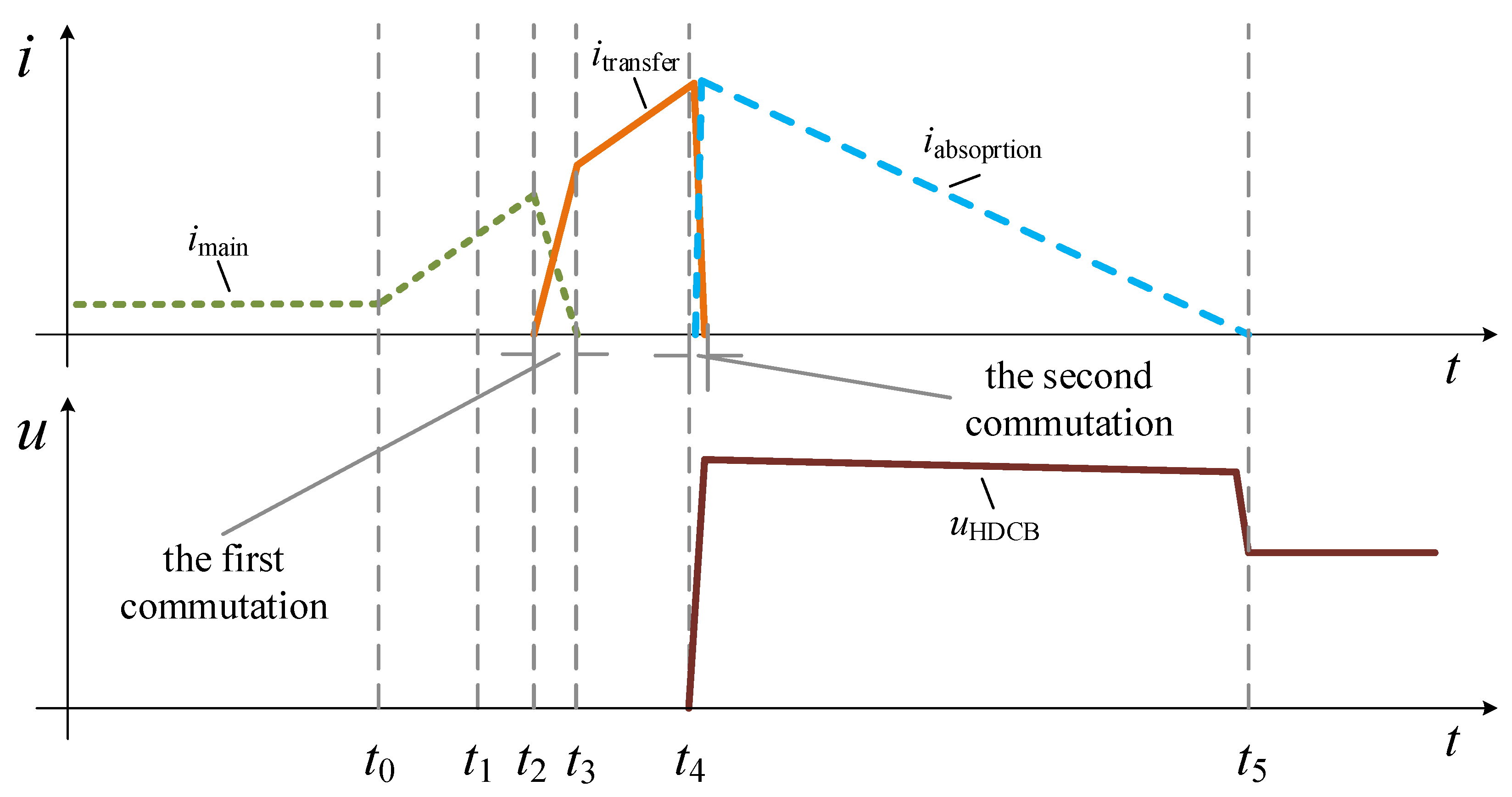
3. Fault Current Interruption Principle

The basic structure of the modular-cascaded HDCB is shown in Figure 5, and consisted of the main branch, transfer branch, and absorption branch [28]. The main branch was composed of an ultra-fast mechanical switch (UMS) with multi-breaks and several insulated gate bipolar transistor (IGBT)-based full-bridge power electronic modules, mainly used to conduct nominal current and assist in transferring fault current. The transfer branch consisted of a large quantity of cascaded diode-based full-bridge power electronic modules in series, and was mainly utilized to bear the fault current within a short time and establish a transient breaking voltage. An absorption branch comprised of metal oxide varistors (MOVs) was used to limit the transient breaking voltage and dissipate the energy stored in the DC system.
The fault current interruption sequence by means of the HDCB is shown in Figure 6, where imain, itransfer and iabsorption indicate the currents of the main branch, transfer branch and absorption branch respectively, and uHDCB is the port-voltage of the HDCB. The corresponding fault current interruption sequence is as follows:
(1)
t0: a short-circuit fault occurs on the DC transmission line.
(2)
t1: local HDCB receives the non-unit main protection action order from the DC line-protection system.
(3)
t2: local HDCB starts its first commutation procedure to shift the fault current from its main branch to its transfer branch, which takes about 0.6 ms.
(4)
t3: the UMS starts the non-arcing switching off operation once the fault current flowing through the main branch is forced to zero, which takes about 2 ms.
(5)
t4: the local HDCB starts its second commutation procedure to force the fault current to shift from its transfer branch to its absorption branch, which takes about 0.1 ms. In this process, the port-voltage of the local HDCB rises from zero to a higher transient breaking voltage within a very short time owing to the triggered MOVs in the absorption branch.
(6)
t5: the fault current is forced to zero with the help of the higher transient breaking voltage, and eventually the port-voltage of the local HDCB equals the DC bus voltage after the breaking operation.

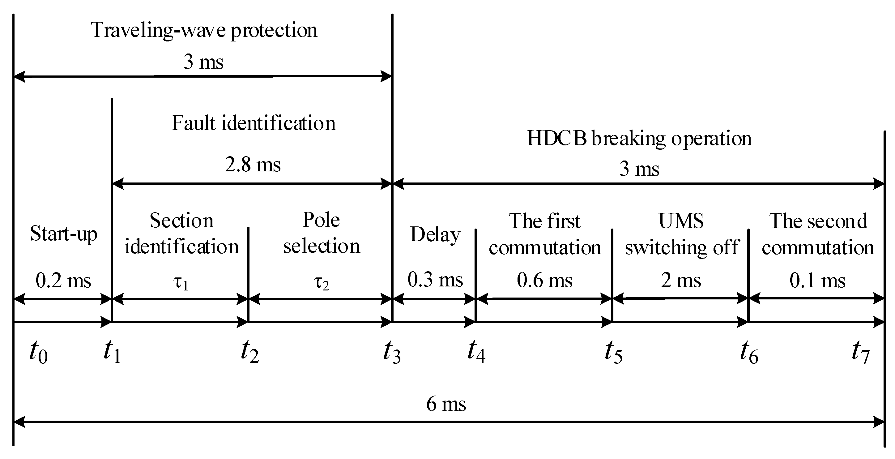
4. Coordination Strategy

The Zhangbei ±500 kV VSC-based DC grid demonstration project—which will be the first VSC-based DC grid in the world—is being constructed to promote the development and utilization of renewable energy in the Zhangbei area of China’s Hebei province. This project is designed as a symmetrical bipolar system, with an MMC based on a half-bridge sub-module and OHLs is adopted. According to the requirements of this project, the DC line main protection action instruction should be output within 3 ms in consideration of the minimum 3 ms breaking time of the present HDCB. Therefore, both the DC line main protection action instruction output time and HDCB breaking time were 3 ms in this paper.

4.1. Traditional Strategy

The traditional coordination strategy is shown in Figure 7, with the TW protection and the HDCB breaking operation in the serial mode. In other words, the TW protection algorithm including the criteria of start-up, fault section identification and fault pole selection was successively executed within 3 ms, then the local HDCB operated according to the corresponding TW protection output action instruction. As shown in the traditional coordination strategy, the total protection action time is the sum of the TW protection action time and the HDCB breaking time.
According to the traditional coordination strategy, the total protection action time was 6 ms. In actual engineering, the longer total protection action time may cause two negative effects on the VSC-based DC grid characterized by “low damping”:
(1) The MMC closer to the fault position may be blocked due to the shorter time margin.
Once the MMC closer to the fault position is blocked due to the shorter time margin, during the relatively longer period from blocking to deblocking, the DC voltage will oscillate greatly because of the unbalanced active power.
(2) Power electronic devices may be damaged because of the larger fault current.
Once the rapidly rising fault current exceeds the endurance capacity of the power electronic devices, these power electronic devices in the main equipment are at risk of damage.
In order to reduce the above risks and ensure the maximum continuous and reliable operation of the VSC-based DC grid, it is necessary to redesign the traditional coordination strategy and put forward an optimizing coordination strategy.

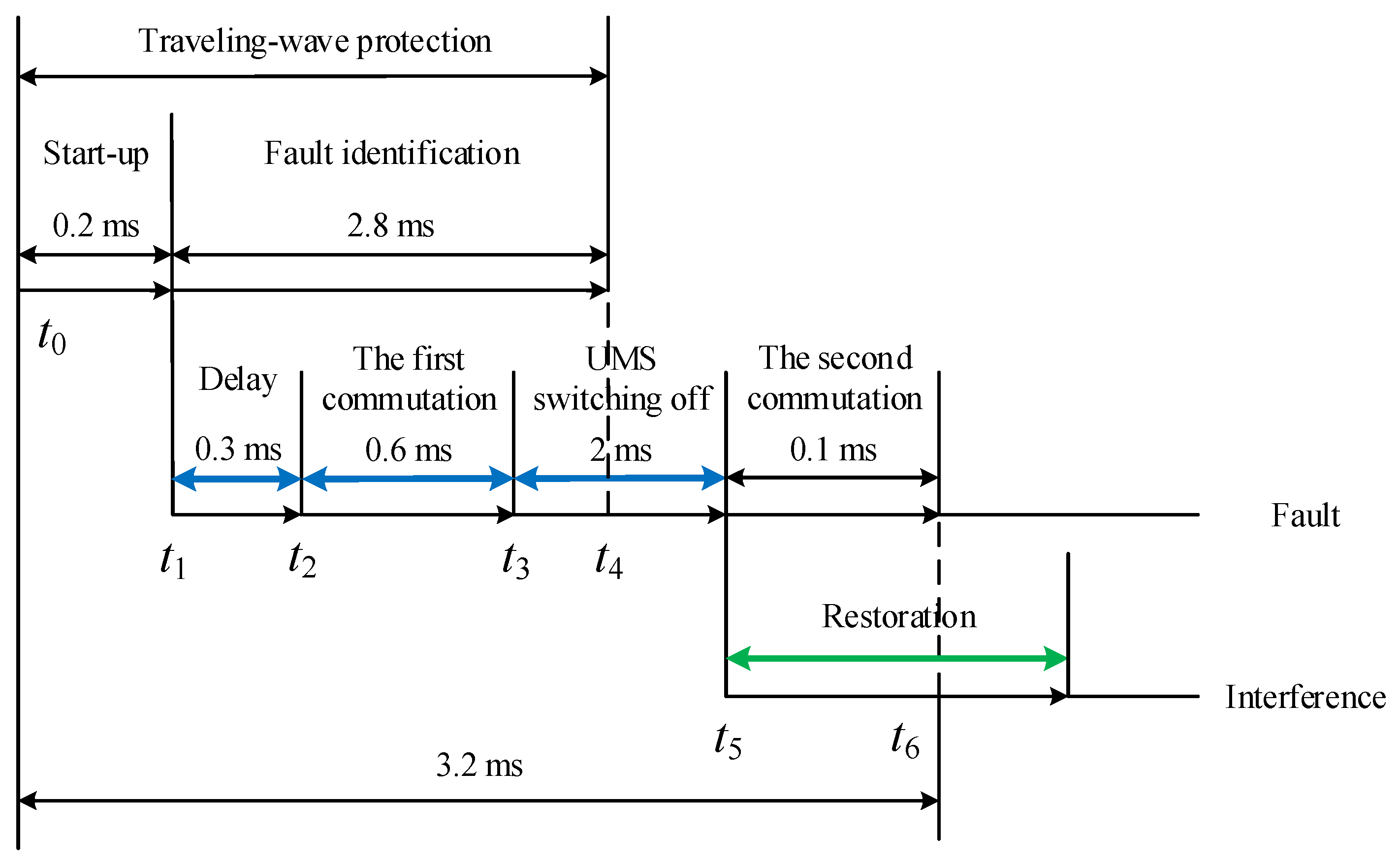
4.2. Proposed Strategy

As mentioned above, the total protection action time is a key factor of the protection technical route based on converters without a fault current interruption capability and DCBs. Reducing the total protection action time can not only reduce the risks arising from the blocking of the MMC closer to the fault position and damage to the power electronic devices, but is also important in ensuring the maximum continuous and reliable operation of the whole VSC-based DC grid.
In order to reduce the total protection action time, based on the local detection signal an optimizing coordination strategy that takes the start-up output signal of line main protection as the pre-operation instruction of the corresponding HDCB was proposed.
The optimizing coordination strategy between TW protection and HDCB is shown in Figure 8. After a 0.3 ms time delay, once receiving the TW protection start-up signal instruction, the local HDCB first performs operations including the first commutation and switching off the UMS, then decides whether to carry out the restoration operation according to the TW protection action instruction. If there is a failure on the DC transmission line, the total protection action time can be reduced to 3.2 ms.
As shown in Figure 8, the sequence of the optimizing coordination strategy between TW protection and the HDCB is:
(1)
t0: the line protection system receives a fault TW signal.
(2)
t1: the TW protection start-up signal is outputted.
(3)
t2: after a 0.3 ms time delay, the local HDCB starts to perform the first commutation operation.
(4)
t3: once the fault current flowing through the main branch is forced to zero, the UMS starts the non-arcing switching-off operation.
(5)
t4: the TW protection action instruction is output.
(6)
t5: the UMS non-arcing switching-off operation ends.
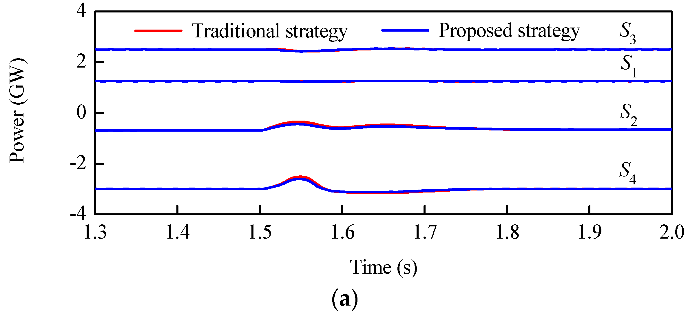
If a fault is determined according to the TW protection action instruction, the local HDCB will perform the second commutation operation. In contrast, if an interference is determined, the local HDCB will implement the restoration operation.
Compared with the traditional coordination strategy, it can be concluded that the total protection action time can be largely reduced if the proposed coordination strategy is adopted, and as a result the risks of blocking the MMC closer to the fault position and the damage to power electronic devices can be greatly reduced.

5. Simulations

To verify the feasibility and validity of the proposed coordination strategy, an electromagnetic transient simulation model of a ±500 kV four-terminal annular VSC-based DC grid, as shown in Figure 9, was built in a PSCAD/EMTDC environment. The VSC-based DC grid operated in a rigid bipolar mode with a metallic return grounded through a resistance of 15 Ω in station S4. The DC voltage was the control object for station S2 and the corresponding reference value was ±500 kV. The active power is the control object for the other stations, and the corresponding reference values for S1, S3 and S4 were 1250 MW, 3000 MW and −3000 MW, respectively.
Without a loss of generality, research around the line OHL34 is described in this section. At t = 1.5 s, a temporary positive pole-to-ground short-circuit fault f, the duration time of which was 100 ms, occurred 0.5 km away from station S2. About 0.2 ms later, the TW protection start-up signal instruction was outputted to the local HDCB43. A total of 0.3 ms later, the HDCB34p located on the positive-pole line started to successively perform the first commutation operations and the UMS non-arcing switching-off. At about t = 1.503 s, the TW protection action instruction was outputted to HDCB43p. At about t = 1.5032 s, the local HDCB34p performed the second commutation operation to determine fault f. The simulation results based on the different coordination strategies between the TW protection and the HDCB were compared and analyzed.
As shown in Figure 10a, short-term active power fluctuations were discovered in all stations with both coordination strategies, however, the maximum active power fluctuation of station S4 was reduced by about 12% compared with the traditional strategy. In Figure 10b, the DC voltage of station S3 returned to its original stable state after a short period of oscillation with both coordination strategies, nevertheless, the maximum DC voltage drop-off of the same station was reduced by about 7.6% after optimization. It can be observed from Figure 10c that the maximum drop-off of the upper arm current in phase A of station S3 was reduced by about 26% by the optimization. As depicted in Figure 10d, based on the optimizing strategy, the maximum increase of the fault current from S3–S4 was reduced by about 39%. In Figure 10e, the maximum increase of the fault current flowing through the transfer branch in HDCB34p was also reduced by about 39%, as the HDCB34p was connected with the OHL34 in series.
It can be concluded from the above simulation results that based on the proposed coordination strategy, if there is a failure on the DC transmission line, no matter the fault type (positive pole-to-ground short-circuit fault, negative pole-to-ground short-circuit fault and pole-to-pole short-circuit fault), the total protection action time can be reduced to 3.2 ms. As a result, the risks of blocking the MMC closer to the fault position and damage to power electronic devices can be reduced greatly. Therefore, the overall performance of the proposed strategy was superior to that of the traditional strategy owing to the shorter total protection action time.

6. Conclusions

The “low damping” characteristic of VSC-based DC grids places stringent requirements on the action speed of fault line isolation. This paper proposed an optimized coordination strategy between the line main protection and a hybrid DC breaker for VSC-based DC grids using overhead transmission lines, which takes the start-up output signal of the line main protection as the pre-operation instruction for the corresponding hybrid DC breaker. Referring to the Zhangbei ±500 kV VSC-based DC grid demonstration project, taking the non-unit TW protection as line main protection, the feasibility and validity of the proposed coordination strategy was verified through simulation. As a result, the risks of blocking the MMC closer to the fault position and of damage to power electronic devices in the main equipment can be effectively reduced in virtue of the shorter total protection action time.
The sequential auto-reclosing strategy for HDCBs in VSC-based DC grids using overhead transmission lines will be examined in future research.

Author Contributions

Conceptualization, X.Z.; Methodology, X.Z.; Software, L.G.; Validation, G.Z.; Writing—Original Draft Preparation, X.Z.; Writing—Review and Editing, X.Z.; Supervision, R.J.; Data Curation, X.P.

Funding

This research was funded by the National Natural Science Foundation of China (51779206).

Acknowledgments

The authors would like to thank the National Natural Science Foundation of China (51779206) for its financial support.

Conflicts of Interest

The authors declare no conflict of interest.

References

  1. Flourentzou, N.; Agelidis, V.G.; Demetriades, G.D. VSC-based HVDC power transmission systems: An overview. IEEE Trans. Power Electron. 2009, 24, 592–602. [Google Scholar] [CrossRef]
  2. Nami, A.; Liang, J.; Dijkhuizen, F.; Demetriades, G.D. Modular multilevel converters for HVDC applications: Review on converter cells and functionalities. IEEE Trans. Power Electron. 2015, 30, 18–36. [Google Scholar] [CrossRef]
  3. Liu, J.; Tai, N.; Fan, C. Transient-voltage-based protection scheme for DC line faults in the multiterminal VSC-HVDC system. IEEE Trans. Power Deliv. 2017, 32, 1483–1494. [Google Scholar] [CrossRef]
  4. Li, S.; Chen, W.; Yin, X.; Chen, D. Protection scheme for VSC-HVDC transmission lines based on transverse differential current. IET Gener. Transm. Dist. 2017, 11, 2805–2813. [Google Scholar] [CrossRef]
  5. Li, X.; Song, Q.; Liu, W.; Rao, H.; Xu, S.; Li, L. Protection of nonpermanent faults on DC overhead lines in MMC-based HVDC systems. IEEE Trans. Power Deliv. 2013, 28, 483–490. [Google Scholar] [CrossRef]
  6. Wu, Y.; Lü, Z.; He, Z.; Kong, M.; Zhou, X.; Fan, Z. Study on the Protection Strategies of HVDC Grid for Overhead Line Application. Proc. CSEE 2016, 36, 3726–3733. (In Chinese) [Google Scholar]
  7. Zhang, S.; An, T.; Pei, X.; Yang, J.; Pang, H.; Zhao, C. Reclosing Strategy for Hybrid DC Circuit Breakers. Autom. Electr. Power Syst. 2019, 43, 129–136. (In Chinese) [Google Scholar]
  8. Pei, X.; Tang, G.; Zhang, S. Sequential auto-reclosing strategy for hybrid HVDC breakers in VSC-based DC grids. J. Mod. Power Syst. Clean Energy 2018. [Google Scholar] [CrossRef]
  9. Xue, S.; Lian, J.; Qi, J.; Fan, B. Pole-to-ground fault analysis and fast protection scheme for HVDC based on overhead transmission lines. Energies 2017, 10, 1059. [Google Scholar] [CrossRef]
  10. Wang, X.; Yang, S.; Xu, L.; Zhang, J.; Lin, W.; Wen, J. A transient voltage-based DC fault line protection scheme for MMC-based DC grid embedding DC breakers. IEEE Trans. Power Deliv. 2019, 34, 334–345. [Google Scholar]
  11. Zhao, P.; Chen, Q.; Sun, K. A novel protection method for VSC-MTDC cable based on the transient DC current using the S transform. Int. J. Electr. Power Energy Syst. 2018, 97, 229–308. [Google Scholar] [CrossRef]
  12. Sadegh, A.; Majid, S.; Moein, A.; Abbas, H. A TW-based methodology for wide-area fault location in multiterminal DC systems. IEEE Trans. Power Deliv. 2014, 29, 2552–2560. [Google Scholar]
  13. Tong, N.; Lin, X.; Li, Y.; Hu, Z.; Jin, N.; Wei, F.; Li, Z. Local measurement-based ultra-high-speed main protection for long distance VSC-MTDC. IEEE Trans. Power Deliv. 2019, 34, 353–364. [Google Scholar] [CrossRef]
  14. Tang, L.; Dong, X.; Shi, S.; Kong, M.; Qiu, Y. Principle and implementation of ultra-high-speed travelling wave based protection for transmission line of flexible HVDC grid. Power Syst. Technol. 2018, 42, 3176–3186. (In Chinese) [Google Scholar]
  15. The hybrid HVDC breaker: An innovation breakthrough enabling reliable HVDC grids. Available online: https://new.abb.com/docs/default-source/default-document-library/hybrid-hvdc-breaker---an-innovation-breakthrough-for-reliable-hvdc-gridsnov2012finmc20121210_clean.pdf?sfvrsn=2 (accessed on 17 April 2019).
  16. Grieshaber, W.; Violleau, L. Development and test of a 120 kV direct current circuit breaker. In Proceedings of the 45th CIGRE Session, Paris, France, 25–29 August 2014; pp. 1–11. [Google Scholar]
  17. Zhou, W.; Wei, X.; Zhang, S.; Tang, G.; He, Z.; Zheng, J.; Shan, Y.; Gao, C. Development and test of a 200kV full-bridge based hybrid HVDC breaker. In Proceedings of the 17th European Conference on Power Electronics and Applications (EPE’15 ECCE-Europe), Geneva, Switzerland, 8–10 September 2015; pp. 1–10. [Google Scholar]
  18. Ding, X.; Tand, G.; Han, M.; Gao, C.; Wang, G. Analysis of the Turn-off Stress on Hybrid DC Circuit Breaker With IGBT Series Valve. Proc. CSEE 2018, 38, 1846–1856. (In Chinese) [Google Scholar]
  19. Ding, X.; Tand, G.; Han, M.; Gao, C.; Wang, G. Characteristic Parameters Extraction and Application of the Hybrid DC Circuit Breaker in MMC-HVDC. Proc. CSEE. 2018, 38, 309–319. (In Chinese) [Google Scholar]
  20. Liu, G.; Xu, F.; Xu, Z.; Zhang, Z.; Tang, G. Assembly HVDC Breaker for HVDC Grids With Modular Multilevel Converters. IEEE Trans. Power Electron. 2017, 32, 931–941. [Google Scholar] [CrossRef]
  21. Liu, W.; Liu, F.; Zhuang, Y.; Zha, X.; Chen, C.; Yu, T. A multiport circuit breaker-based multiterminal DC system fault protection. IEEE J. Emerg. Sel. Top. Power Electron. 2019, 7, 118–128. [Google Scholar] [CrossRef]
  22. Ataollah, M.; Dirk, V.; Nuno, S.; Helder, L.; Adriano, C. Multiport hybrid HVDC circuit breaker. IEEE Trans. Indus Electron. 2018, 65, 309–320. [Google Scholar]
  23. Ataollah, M.; Oriol, G.; Nuno, S.; Adriano, C. Current flow controlling hybrid DC circuit breaker. IEEE Trans. Power Electron. 2018, 33, 1323–1334. [Google Scholar]
  24. Tang, L.; Dong, X. Study on the characteristic of travelling wave differential current on half-wave-length AC transmission lines. Proc. CSEE 2017, 37, 2261–2269. (In Chinese) [Google Scholar]
  25. Pei, X.; Tang, G.; Zhang, S. A Novel Pilot Protection Principle Based on Modulus TW Currents for Voltage-Sourced Converter Based High Voltage Direct Current (VSC-HVDC) Transmission Lines. Energies 2018, 11, 2395. [Google Scholar] [CrossRef]
  26. Lei, A.; Dong, X.; Shi, S.; Wang, B.; Terzija, V. Equivalent traveling waves based current differential protection of EHV/UHV transmission lines. Int. J. Electr. Power Energy Syst. 2018, 97, 282–289. [Google Scholar] [CrossRef]
  27. Tang, L.; Dong, X.; Luo, S.; Shi, S.; Wang, B. A New Differential Protection of Transmission Line Based on Equivalent Travelling Wave. IEEE Trans. Power Deliv. 2017, 32, 1359–1369. [Google Scholar] [CrossRef]
  28. Ding, X.; Tand, G.; Han, M.; Gao, C.; Wang, G. Design and equivalence evaluation of type test for hybrid DC circuit breaker. Power Syst. Technol. 2018, 42, 72–78. (In Chinese) [Google Scholar]
Figure 1. Distributed parameter model.
Energies 12 01462 g001
Figure 2. Schematic diagram of the fault section in the VSC-based DC grid.
Energies 12 01462 g002
Figure 3. Peterson equivalent circuit.
Energies 12 01462 g003
Figure 4. Positive pole-to-ground fault.
Energies 12 01462 g004
Figure 5. Basic structure of the hybrid DC breaker (HDCB).
Energies 12 01462 g005
Figure 6. Fault current interruption sequence.
Energies 12 01462 g006
Figure 7. Traditional strategy.
Energies 12 01462 g007
Figure 8. Proposed strategy.
Energies 12 01462 g008
Figure 9. A ±500 kV four-terminal VSC-based DC grid.
Energies 12 01462 g009
Figure 10. Simulation results: (a) active power of all stations; (b) DC voltage of station S3; (c) the upper arm current in phase A of station S3; (d) DC current of OHL34 from S3–S4; (e) currents of all branches in HDCB34p.
Energies 12 01462 g010aEnergies 12 01462 g010b

