Article

Sensorless Control for IPMSM Based on Adaptive Super-Twisting Sliding-Mode Observer and Improved Phase-Locked Loop

1
School of Electrical and Power Engineering, China University of Mining and Technology, Xuzhou 221116, China
2
Xuzhou Yirui Construction Machinery Co. Ltd., Xuzhou 221000, China
*
Author to whom correspondence should be addressed.
Energies 2019, 12(7), 1225; https://doi.org/10.3390/en12071225
Submission received: 6 March 2019 / Revised: 23 March 2019 / Accepted: 26 March 2019 / Published: 29 March 2019
(This article belongs to the Special Issue Advances in Rotating Electric Machines)

Abstract

:
In traditional sensorless control of the interior permanent magnet synchronous motors (IPMSMs) for medium and high speed domains, a control strategy based on a sliding-mode observer (SMO) and phase-locked loop (PLL) is widely applied. A new strategy for IPMSM sensorless control based on an adaptive super-twisting sliding-mode observer and improved phase-locked loop is proposed in this paper. A super-twisting sliding-mode observer (STO) can eliminate the chattering problem without low-pass filters (LPFs), which is an effective method to obtain the estimated back electromotive forces (EMFs). However, the constant sliding-mode gains in STO may cause instability in the high speed domain and chattering in the low speed domain. The speed-related adaptive gains are proposed to achieve the accurate estimation of the observer in wide speed range and the corresponding stability is proved. When the speed of IPMSM is reversed, the traditional PLL will lose its accuracy, resulting in a position estimation error of 180°. The improved PLL based on a simple strategy for signal reconstruction of back EMF is proposed to ensure that the motor can realize the direction switching of speed stably. The proposed strategy is verified by experimental testing with a 60-kW IPMSM sensorless drive.

1. Introduction

Recently, interior permanent magnet synchronous motors (IPMSMs) have been extensively utilized in the fields of electromechanical drives, electric vehicles, and numerical control servo systems due to their robustness, high efficiency, high power density, and compactness [1,2,3,4]. The usage of position sensors decreases the reliability and increases the cost and volume of IPMSM drives. In order to overcome these shortcomings caused by the use of mechanical position sensors, sensorless control technology has become one of the important research directions in related fields [5,6]. Generally, sensorless control strategies can be divided into two categories. The first one is called signal injection methods [7,8,9]. This method is based on the salient pole effect of the motor, which is mainly used in zero and low speed domains. The second one is called back EMF based methods [10,11,12,13,14,15,16,17,18,19], which utilizes the estimated back EMF signals to obtain the position information of the motor. Because the magnitude of back EMF is in proportion to the speed of the motor, the performance of back EMF based methods at ultra-low and zero speed is extremely poor [11]. Hence, back EMF based methods and signal injection methods are usually combined to achieve sensorless control for a whole speed range [12,13,14]. Back EMF based methods primarily includes the model adaptive method (MRAS) [16], the Kalman filtering method (EKF) [17], and the sliding mode observer (SMO) [2,18,19], etc. Compared with MRAS and EKF, SMO has simpler structure and stronger robustness. Hence, SMO is extensively applied in sensorless control strategy [19].
The signum function used in traditional SMO can introduce high frequency harmonics into the estimated signals, which eventually lead to the inevitable chattering phenomenon. Therefore, low-pass filters (LPFs) are commonly utilized to smooth the estimated signals. However, the LPFs in turn bring the disadvantages of phase delay of estimated signals. In [20], signum function is utilized to reduce the SMO chattering phenomenon caused by sigmoid function. In [21], an adaptive filter is proposed to reduce the negative effects of LPFs. However, these methods cannot completely avoid phase delay caused by LPFs. In [22,23], the super-twisting algorithm is proposed to eliminate the chattering phenomenon caused by signum function. The super-twisting sliding mode observer (STO) can effectively eliminate the sliding-mode chattering phenomenon without compromising robustness and avoid the use of LPFs. In [24], the stability of STO is further analyzed by using the Lyapunov function and the corresponding stability conditions are given. In [25], the sensorless control strategy based on STO and resistance identification is proposed for SPMSM. Resistance identification enhances the robustness of the super-twisting sliding mode observer. Although STO performs well in reducing chattering, there is still a problem to be solved. When the constant sliding-mode gains are adopted in this method, the sliding-mode gains should be big enough to meet the stability condition in the wide speed range. But the large sliding-mode gains will lead to a large chattering phenomenon, especially in a low speed domain [19].
Traditionally, the position information is obtained by the estimated back electromotive forces through arc-tangent method directly. However, the arc-tangent function makes position information susceptible to harmonics and noises. In order to improve estimation performance, the quadrature phase-locked loop algorithm is proposed in [6], which is called the traditional PLL in this paper. High-order harmonics can be filtered out due to the special structure of PLL. When the speed of IPMSM is reversed, the traditional PLL will lose its accuracy, resulting in a position estimation error of 180°. The reason for such drawback is that the sign of the back EMFs has an effect on the sign of the equivalent position error [26,27]. To solve the aforementioned problem, Refs. [26,27] proposed a kind of PLL, which constructs the equation of the equivalent position error based on tangent function. Such a scheme may overcome the problem, but it brings complexity to the algorithm and it is vulnerable to harmonics and noises due to the introduction of a tangent function.
In this paper, a new strategy based on adaptive super-twisting sliding mode observer and improved PLL for IPMSM sensorless control is proposed to overcome aforementioned limitations. Super-twisting sliding-mode observer is utilized to obtain the estimated back electromotive forces. Moreover, speed-related adaptive gains are proposed to achieve accurate estimation in a wide speed domain so that they widen the speed range of the super-twisting sliding-mode observer. On the basis of existing stability conditions in [24], the stability of the proposed adaptive STO is proved in this paper. To improve the shortcomings of the above-mentioned two kinds of PLL, a simple strategy for signal reconstruction of back EMF is proposed. Based on this strategy, the improved PLL can overcome the limitation of speed reversal existing in traditional PLL without the introduction of tangent function. Besides, the improved PLL has simple structure, great steady performance, and transient response. Finally, the proposed strategy based on adaptive STO and improved PLL is verified by experimental testing with a 60-kW IPMSM sensorless drive.

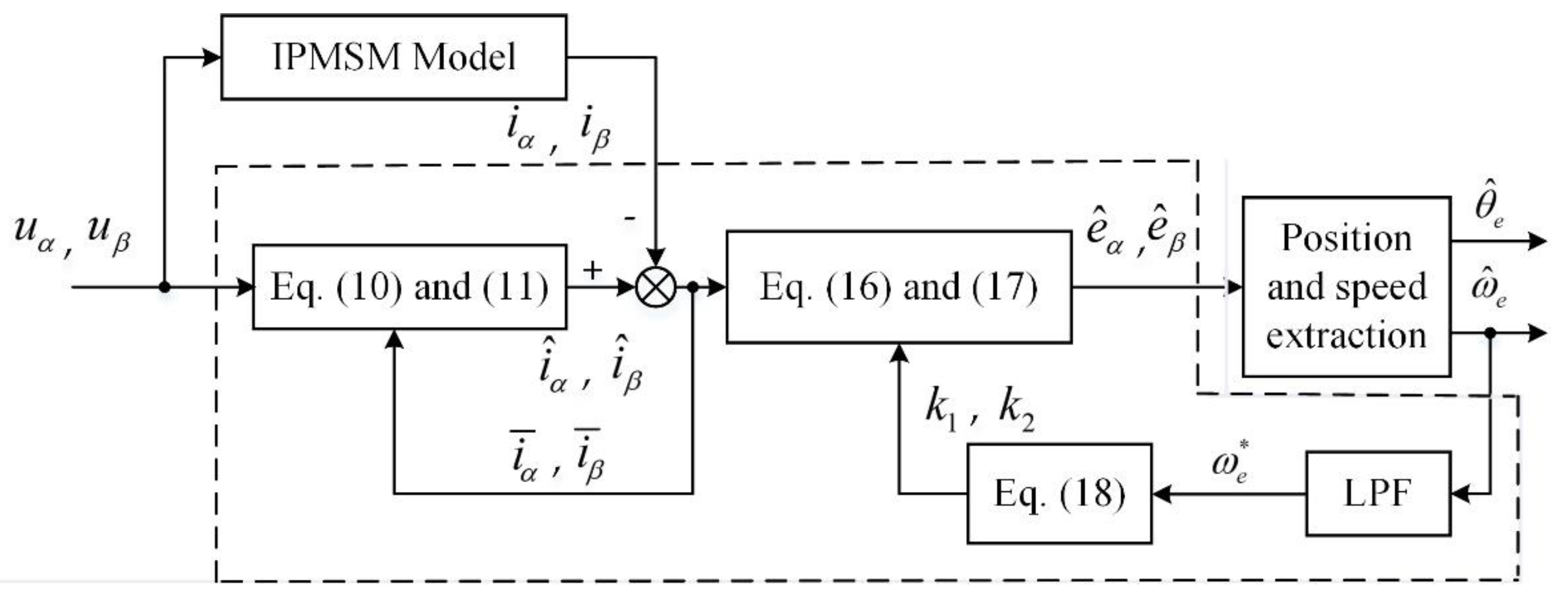
2. Adaptive Super-Twisting Sliding-Mode Observer

For the sake of convenience, magnetic saturation is neglected and it is assumed that the flux linkage distribution is perfectly sinusoidal. The model of IPMSM is shown in Figure 1. The ABC, αβ and dq frames represent the natural, the stationary, and the rotating reference frames, respectively.
The mathematic model of IPMSM in αβ stationary reference frame is expressed as
u α = R i α + L d d i α d t + ω e ( L d L q ) i β + e α
u β = R i β + L q d i β d t ω e ( L d L q ) i α + e β
where u α , u β are stator voltages; i α , i β are stator currents; R is stator resistance; ω e is electrical rotor speed; ψ f is PM flux linkage; and L d , L q are stator inductances. e α and e β are the α β -axis back EMFs of IPMSM, satisfying e α = E s i n θ and e β = E c o s θ . θ is the rotor position and E is the amplitude of back EMF [28], satisfying
E = ( L d L q ) ( ω e i d d i q d t ) + ω e ψ f

2.1. Super-Twisting Algorithm

A. Levant proposed the super-twisting algorithm to eliminate the chatter caused by the signum function in [23,29]. The fundamental form of this algorithm is written as follows:
d x ^ 1 d t = k 1 | x ^ 1 x 1 | sign ( x ^ 1 x 1 ) + x ^ 2 + ρ 1
d x ^ 2 d t = k 2 sign ( x ^ 1 x 1 ) + ρ 2
where x i , x ^ i , k i , sign(), and ρ i are state variables, estimation of state variables, sliding-mode gains, signum function, and perturbation terms, respectively. The corresponding conditions of the stability of the super-twisting algorithm have been educed in [24]. If ρ 1 and ρ 2 in Equations (6) and (7) satisfy the following conditions:
ρ 1 δ 1 | x 1 | 1 2 ,   ρ 2 = 0
where δ 1 is a positive constant and the sliding-mode gains k 1 and k 2 meet the condition:
k 1 > 2 δ 1 ,   k 2 > k 1 5 δ 1 k 1 + 4 δ 1 2 2 ( k 1 2 δ 1 )
the stability of the system can be guaranteed.

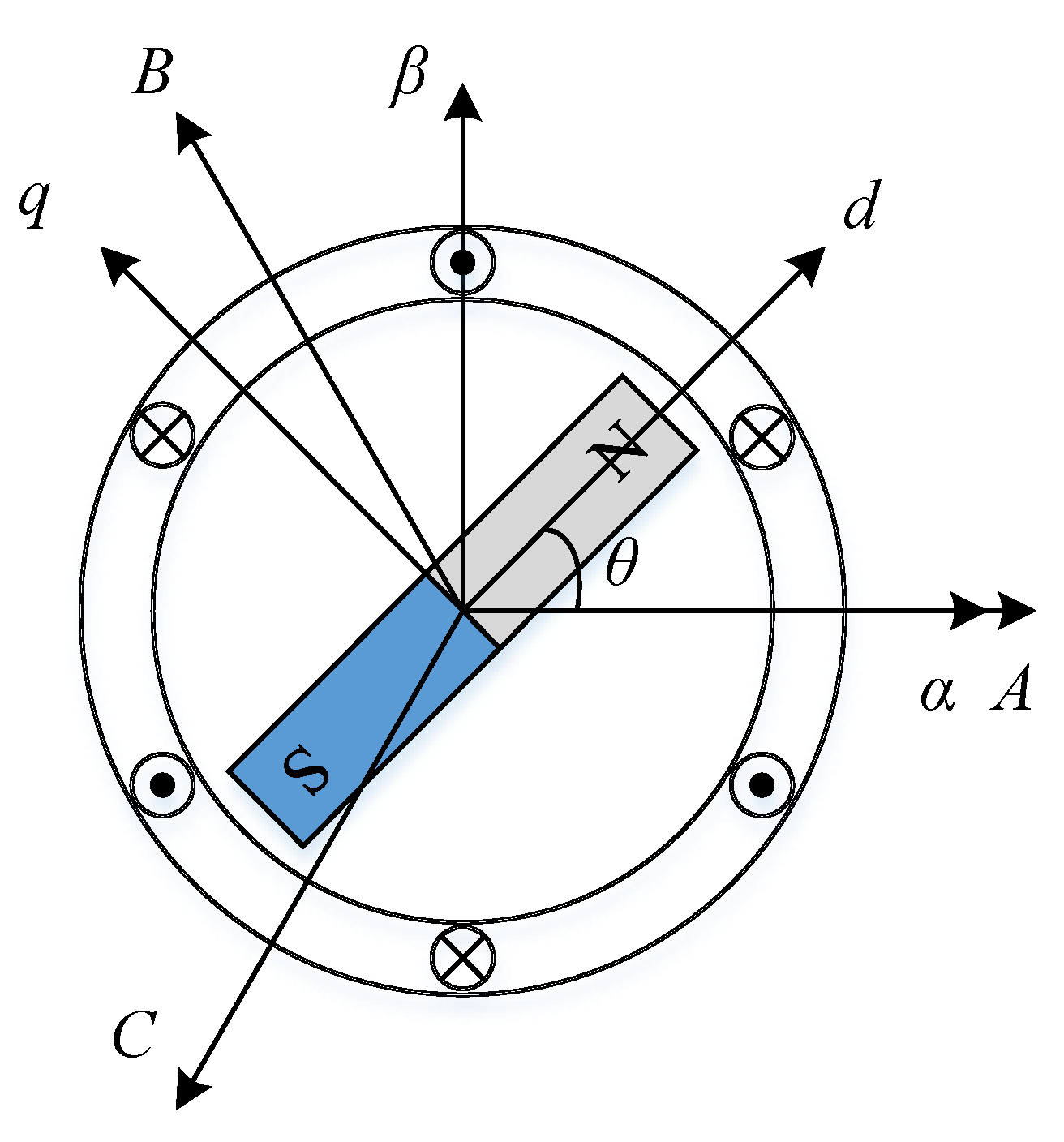
2.2. Super-Twisting Sliding Mode Observer for IPMSM Sensorless Control

To estimate the back EMFs conveniently, the mathematic mode of IPMSM shown in Equations (3) and (4) is organized into the current model:
d i α d t = R L d i α ω e L d L q L d i β + u α L d e α L d
d i β d t = R L d i β + ω e L d L q L d i α + u β L d e β L d
The estimated currents are taken as state variables in Equations (4) and (5), then the STO for IPMSM sensorless control be represented as
d i ^ α d t = R L d i ^ α ω ^ e L d L q L d i ^ β + u α L d k 1 L d | i ¯ α | 1 2 sign ( i ¯ α ) 1 L d k 2 sign ( i ¯ α ) d t
d i ^ β d t = R L d i ^ β + ω ^ e L d L q L d i ^ α + u β L d k 1 L d | i ¯ β | 1 2 sign ( i ¯ β ) 1 L d k 2 sign ( i ¯ β ) d t
where i ¯ α = i ^ α i α , i ¯ β = i ^ β i β and ˆ represents the estimated variable. It should be noticed that, differently from the STO for SPMSM sensorless control in [26], the perturbation term ρ 1 in Equation (4) for IPMSM sensorless control is replaced by R L d i ^ α ω ^ e L d L q L d i ^ β + u α L d and R L d i ^ β + ω ^ e L d L q L d i ^ α + u β L d , respectively.
By substituting the perturbation terms into Equation (6) and taking estimated currents as state variables, Equation (6) can be reformulated as
R L d i ^ α ω ^ e L d L q L d i ^ β + u α L d δ 1 | i ^ α | 1 2
R L d i ^ β + ω ^ e L d L q L d i ^ α + u β L d δ 1 | i ^ β | 1 2
If δ 1 is large enough, the stable conditions can be guaranteed easily. By subtracting Equations (8) and (9) from Equations (10) and (11) respectively, the state equations of the current estimation errors can be obtained:
d i ¯ α d t = R L d i ¯ α L d L q L d ( ω ^ e i ^ β ω e i β ) k 1 L d | i ¯ α | 1 2 sign ( i ¯ α ) 1 L d k 2 sign ( i ¯ α ) d t + e α L d
d i ¯ β d t = R L d i ¯ β + L d L q L d ( ω ^ e i ^ α ω e i α ) k 1 L d | i ¯ β | 1 2 sign ( i ¯ β ) 1 L d k 2 sign ( i ¯ β ) d t + e β L d
when STO reaches the sliding surface, it is approximately considered that the estimated value is equal to the actual value ( ω ^ e ω e , i ^ α i α and i ^ β i β ). Then the equivalent control law of the back EMFs is expressed as
e ^ α = k 1 | i ¯ α | 1 2 sign ( i ¯ α ) + k 2 sign ( i ¯ α ) d t
e ^ β = k 1 | i ¯ β | 1 2 sign ( i ¯ β ) + k 2 sign ( i ¯ β ) d t
The linear term k 1 | i ¯ α | 1 2 sign ( i ¯ α ) determines the convergence rate of the STO and the integral term k 2 sign ( i ¯ α ) d t is related to the suppression of chattering phenomena. Hence, k 2 usually has a large value.

2.3. Adaptive Super-Twisting Sliding Mode Observer for IPMSM Sensorless Control

Although STO performs well in reducing chattering, there is still a problem to be solved. When the constant sliding-mode gains are adopted in this method, the sliding-mode gains should be large enough to meet the stable conditions when the IPMSM runs at high speed. However, due to the excessive sliding mode gains, the performance of the STO in the low speed domain will be seriously deteriorated [19]. In order to extract accurate rotor position in wide speed range, the STO for IPMSM with speed-related adaptive gains is proposed in this paper. The speed-related adaptive gains k 1 and k 2 are adopted as
k 1 = l 1 ω e * ,   k 2 = l 2 ω e * 2
ω e * = { ω e m i n 0 ω ^ e < ω e m i n LPF ( ω ^ e ) ω e m i n ω ^ e ω e m a x ω e m a x ω ^ e > ω e m a x
where l 1 and l 2 are adaptive coefficients, ω e m a x is the maximum electrical rotor speed of motor, ω e m i n is the minimum electrical rotor speed allowed by the STO for back EMFs observation. The first-order LPF in the STO is utilized to smooth the gain variations and improve the robustness of the observer in the transient process. Its cut-off frequency is determined according to ω e m a x and switching frequency. The stability of adaptive STO is proved as follows:
In Equations (12) and (13), compared with u α L d and u β L d , R L d i ^ α , ω ^ e L d L q L d i ^ β , R L d i ^ β and ω ^ e L d L q L d i ^ α can be neglected. Then, the perturbation terms can be simplified as
ρ 1 ( i α ) u α L d ,   ρ 1 ( i β ) u β L d
then, Equation (6) can be rewritten as
| ρ 1 ( i α ) | | u α L d | ω e ψ f L d δ 1 | i ^ α | 1 2
when STO reaches the sliding surface, | i ^ α | 1 2 is in a certain range and ω e * ω e . δ 1 is replaced by λ ω e in Equation (21), Equation (21) can be rewritten as
| ρ 1 ( i α ) | | u α L d | ω e ψ f L d λ | i ^ α | 1 2 ω e
This formula can be satisfied by choosing a large λ . Substituting δ 1 = λ ω e , k 1 = l 1 ω e and k 2 = l 2 ω e 2 into Equation (7), Equation (7) can be rewritten as
k 1 = l 1 ω e > 2 δ 1 = 2 λ ω e
k 2 = l 2 ω e 2 > k 1 5 δ 1 k 1 + 4 δ 1 2 2 ( k 1 2 δ 1 ) = l 1 5 λ l 1 + 4 λ 2 2 l 1 4 λ ω e 2
It is obvious that when the adaptive coefficients l 1 and l 2 satisfy the condition l 1 > 2 λ and l 2 > l 1 5 λ l 1 + 4 λ 2 2 l 1 4 λ , the stability conditions of adaptive STO can be satisfied. The black diagram of adaptive STO for IPMSM sensorless control is shown in Figure 2.

3. Acquisition of Position Information

Traditionally, the position information is obtained by the estimated back electromotive forces through arc-tangent method directly.
θ ^ e = arctan · ( e ^ α e ^ β )
The electrical rotor speed can be calculated by ω ^ e = d θ ^ e d t . However, the estimated position and speed is susceptible to noise and harmonics because of the usage of arc-tangent method. Especially when e ^ β crosses zero, the obvious estimation errors may be produced. Ref. [6] proposed the quadrature phase-locked loop algorithm to mitigate the adverse effect. In this paper, this algorithm is called the traditional PLL.

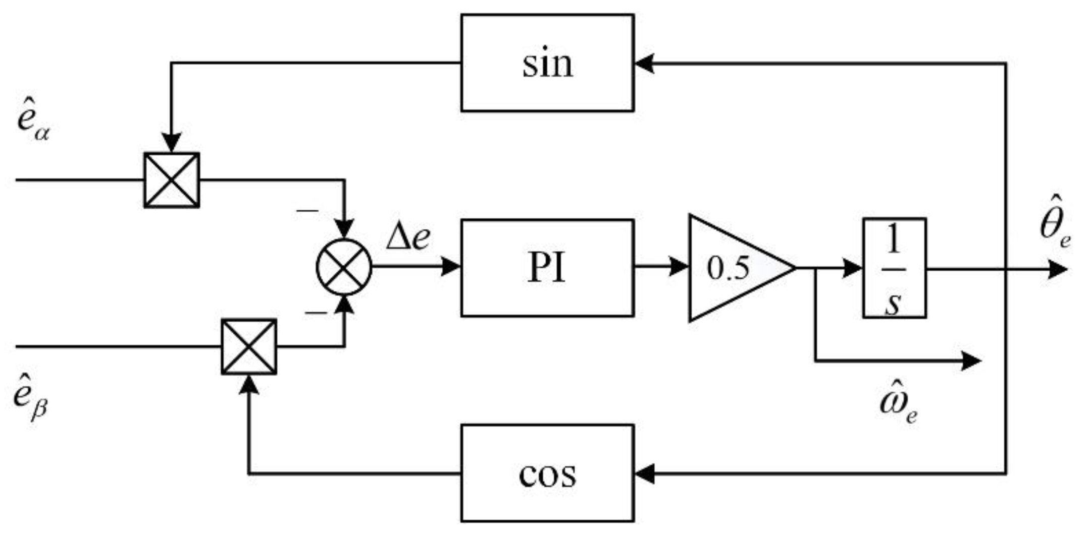
3.1. Traditional PLL

The transfer function of the traditional PLL can be written as
G ( s ) = θ ^ e θ e = E K p s + E K i s 2 + E K p s + E K i
where K p is the proportional gain, K i is the integral gain. The structure of the traditional PLL is represented in Figure 3.
The bode diagram of Equation (26) with different E is shown in Figure 4. As shown in Figure 4, E varies with the rotor speed, so the bandwidth of the PLL is influenced by the operating frequency of motor. This could make the design of system parameters more difficult and deteriorate the accuracy of the position estimation. Therefore, the normalization of the back EMFs is necessary.
By normalizing the estimated back EMF, the equivalent position error e can be written as
e = 1 e ^ α 2 + e ^ β 2 [ e ^ α cos ( θ ^ e ) e ^ β sin ( θ ^ e ) ] = e ^ α n cos ( θ ^ e ) e ^ β n sin ( θ ^ e ) = sin ( θ e ) cos ( θ ^ e ) sin ( θ ^ e ) cos ( θ e ) = sin ( θ e θ ^ e ) θ e θ ^ e
where e ^ α n and e ^ β n are the normalized back EMFs, and the closed-loop transfer function of the traditional PLL with back EMF normalization can be obtained by
G ( s ) = θ ^ e θ e = K p s + K i s 2 + K p s + K i
The traditional PLL has the characteristics of LPF. High-order harmonics can be filtered out due to the special structure of phase-locked loop. However, when the speed of IPMSM is reversed, the traditional PLL will lose its accuracy, resulting in a position estimation error of 180°. When the parameters of PLL are set for one direction of rotation, the estimation of rotor position is correct for this direction only and an error of 180° will be produced in the other direction. Such a drawback makes the traditional PLL not suitable for applications where the motor needs to switch the direction of rotation. The theoretical analysis of the above problem is shown in Section 3.3.

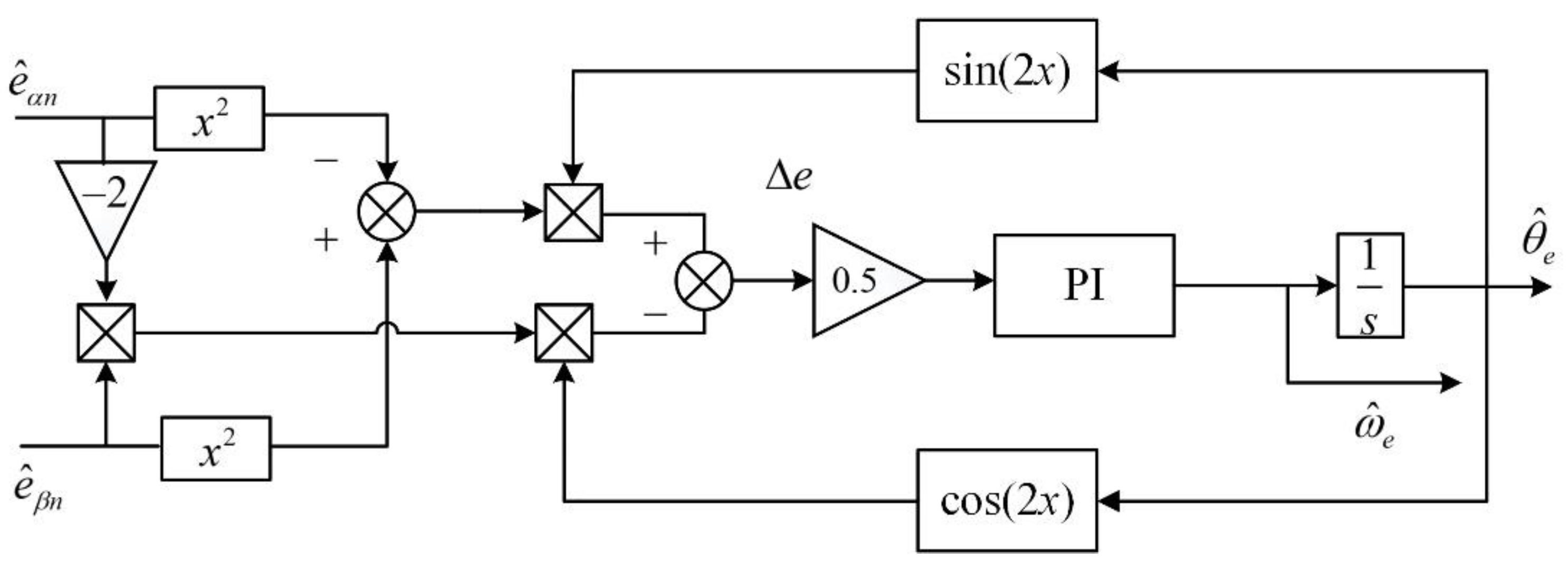
3.2. Tangent-Based PLL

To solve the aforementioned problem, Refs. [26,27] proposed a kind of PLL scheme, which constructs the equivalent position error equation based on tangent function.
e = e ^ α e ^ β sin ( θ ^ e 2 ) cos ( θ ^ e 2 ) 1 + e ^ α e ^ β · sin ( θ ^ e 2 ) cos ( θ ^ e 2 ) = tan ( θ e ) tan ( θ ^ e 2 ) 1 + tan ( θ e ) · tan ( θ ^ e 2 ) = tan ( θ e θ ^ e 2 )
The structure of the tangent-based PLL is shown in Figure 5. When the system achieves the steady point, rotor position can be calculated as
θ e = θ ^ e 2
This kind of PLL can solve the reversal problem. However, it increases the complexity of the algorithm. And it is vulnerable to harmonic and noise interference due to the introduction of tangent function. Especially, during e ^ β crosses zero and the rotor position crosses ± π 2 , the obvious estimation error may occur.

3.3. Improved PLL

The improved PLL is based on a simple EMF signals reconstruction strategy. The structure of the improved PLL is depicted in Figure 6 and the equation of the equivalent position error in the proposed scheme can be expressed as
e = e ^ α n e ^ β n cos ( 2 θ ^ e ) + ( e ^ α n 2 e ^ β n 2 ) 2 sin ( 2 θ ^ e ) = 1 2 [ sin ( 2 θ e ) cos ( 2 θ ^ e ) sin ( 2 θ ^ e ) cos ( 2 θ e ) ] = 1 2 sin ( 2 ( θ e θ ^ e ) )
when the system reaches the stable point, e can be derived as
e = 1 2 sin ( 2 ( θ e θ ^ e ) ) θ e θ ^ e
In the positive speed range of the motor,
e ^ α n = sin ( θ e ) ,   e ^ β n = cos ( θ e )
and the dynamic equations of the traditional PLL with back EMF normalization are represented as
d e θ d t = e ω
d e ω d t = K p cos ( e θ ) e ω K I sin ( e θ )
where e θ = θ e θ ^ e , e ω = ω e ω ^ e . The phase trajectory of the traditional PLL for positive speed is shown in Figure 7a. As shown in Figure 7a, there are three equilibrium points in the system, which are (0,0), ( π ,0) and ( π ,0). Among the three equilibrium points, only (0,0) is stable point. The others are saddle points. That means the trajectories in the phase trajectory of traditional PLL for positive speed will move to the origin. In other words, e θ and e ω can converge to (0,0) in limited time, which meets the requirements of estimation performance.
But when the direction of rotation is reversed, the symbols of the back EMF change and the same symbolic change can be detected on the equivalent position error signal e :
e ^ α n = sin ( θ e ) ,   e ^ β n = cos ( θ e )
e = e ^ α n cos ( θ ^ e ) e ^ β n sin ( θ ^ e ) = sin ( θ e ) cos ( θ ^ e ) + sin ( θ ^ e ) cos ( θ e ) = sin ( θ ^ e θ e ) ( θ e θ ^ e )
And the dynamic equations of the traditional PLL are rewritten as
d e θ d t = e ω
d e ω d t = K p cos ( e θ ) e ω + K I sin ( e θ )
The phase trajectory of the traditional PLL for negative speed is given in Figure 7b. The system has the same three equilibrium points, which are (0,0), ( π ,0) and ( π ,0). However, (0,0) changes into saddle point and ( ± π ,0) become stable points. The trajectories in the nonlinear system depart from (0,0) to reach the stable points ( ± π ,0) so that the system produce a position estimation error of 180°. Although this problem can be solved by resetting the gains of the PI controller, it is difficult to implement in real-time control system. Therefore, the traditional PLL cannot meet the requirements of applications where the motor needs to switch the direction of rotation.
The phase trajectory of the tangent-based PLL for both positive and negative speed is shown in Figure 7c. More details can be found in [26,27]. In this kind of PLL system, (0,0), ( π ,0), and ( π ,0) are three stable points. By setting the proper parameters of PI regulator, e θ and e ω can converge to (0,0). That means the tangent-based PLL can solve the reversal problem. But due to the introduction of tangent function, it is vulnerable to harmonic and noise interference. Especially when e ^ β crosses zero and the position crosses ± π 2 , the obvious estimation errors will be produced. This algorithm is difficult to adopt in practice.
Compared with the traditional PLL and the tangent-based PLL, the improved PLL makes the speed reversal of motor not cause the symbolic change of the equivalent position error e by using a simple back EMF signals reconstruction strategy without tangent function. The dynamic equations are the same for both positive and negative speed and can be represented as
d e θ d t = e ω
d e ω d t = 1 2 [ K p cos ( 2 e θ ) 2 e ω K I sin ( 2 e θ ) ]
There are five equilibrium points in the system, which are (0,0), ( ± π ,0) and ( ± π 2 ,0). In order to confirm the properties of equilibrium points in the system conveniently, the nonlinear equation of state is linearized. The Jacobian matrix J ( e θ , e ω ) for (40) and (41) is represented as
J ( e θ , e ω ) = [ 0 1 2 K p sin ( 2 e θ ) e ω K I cos ( 2 e θ ) K p cos ( 2 e θ ) ]
Substituting ( e θ , e ω ) = ( 0 , 0 ) and ( e θ , e ω ) = ( ± π , 0 ) into (42) respectively, the expression is the same at these points:
J ( e θ , e ω ) ( e θ , e ω ) = ( 0 , 0 ) , ( ± π , 0 ) = [ 0 1 K I K p ]
The eigenvalues of (43) can be expressed as
λ 1 = K p + K p 2 4 K I 2 ,   λ 2 = K p K p 2 4 K I 2
Because K p > 0 and K I > 0 , λ 1 and λ 2 have negative real parts. That means (0,0) and ( ± π ,0) are stable points.
Substituting ( e θ , e ω ) = ( ± π 2 , 0 ) into Equation (42) respectively, the expression is the same at these points:
J ( e θ , e ω ) ( e θ , e ω ) = ( ± π 2 , 0 ) = [ 0 1 K I K p ]
The eigenvalues of Equation (45) can be expressed as
λ 1 = K p + K p 2 + 4 K I 2 > 0 , λ 2 = K p K p 2 + 4 K I 2 < 0
Because λ 1 > 0 and λ 2 < 0 , ( ± π 2 , 0 ) are saddle points in the system. In summary, among the five equilibrium points, (0,0) and ( ± π ,0) are stable points and ( ± π 2 ,0) are saddle points. The phase trajectory of the improved PLL for both positive and negative speed is shown in Figure 7d. Similar to the tangent-based PLL, each of these stable points is a focal point that the neighborhood phase trajectories will be attracted to. Moreover, because there is no introduction of the arctangent function, this method has better robustness than the tangent-based PLL. By selecting the appropriate gains of the PI regulator, e θ and e ω will converge to the origin. That means the motor can switch the speed direction steadily by adopting the proposed PLL.

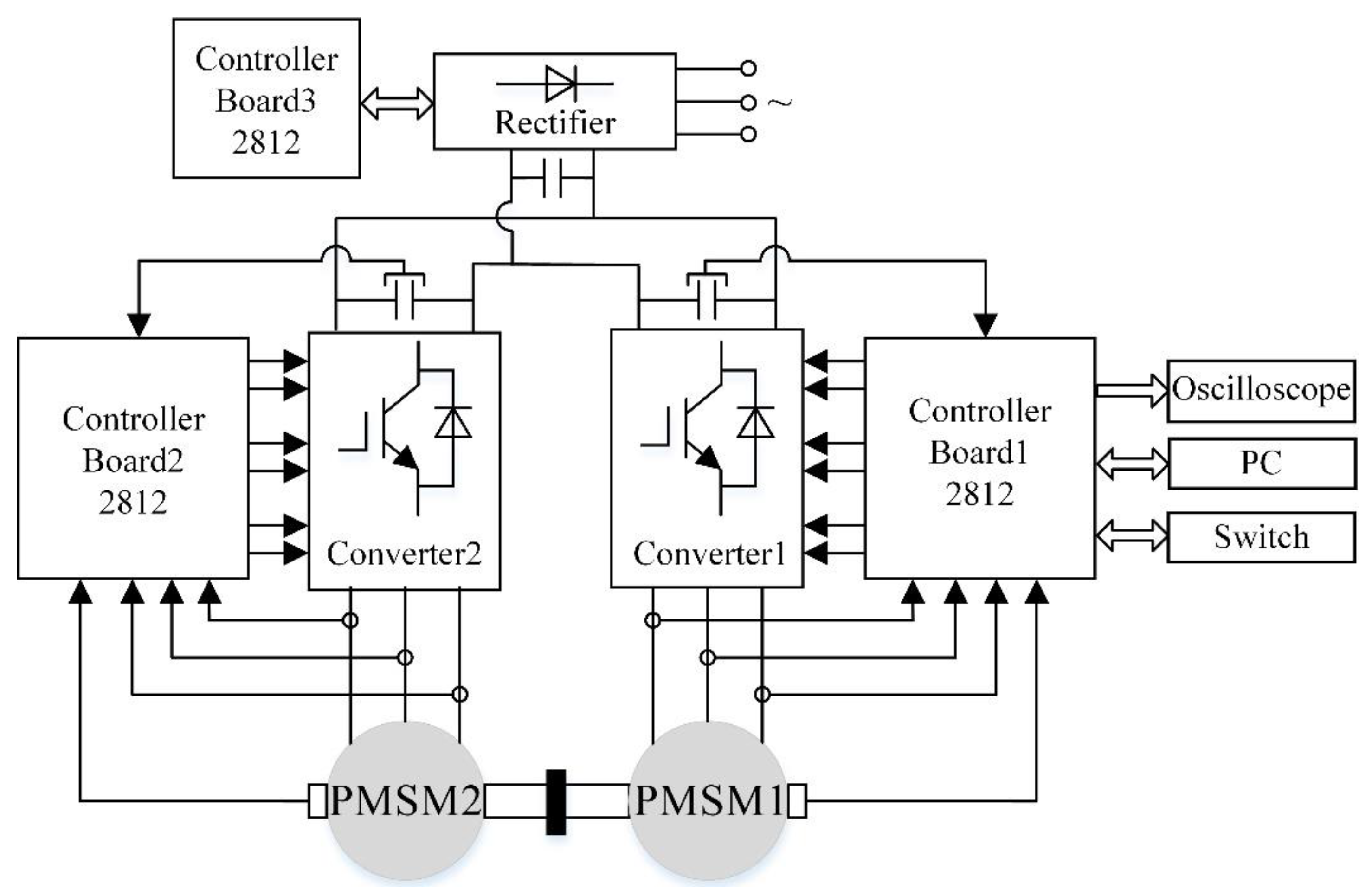
4. Experimental Results

The control diagram of proposed sensorless control strategy for IPMSM based on adaptive STO and improved PLL is shown in Figure 8. The double closed-loop vector control is adopted. The details of the adaptive STO and the improved PLL are shown in Figure 2 and Figure 6, respectively.
An experimental prototype is shown in Figure 9 and the corresponding experimental platform was established as shown in Figure 10. The platform is mainly composed of two water-cooled IPMSMs, one rectifier, two inverters, and three controllers. The motor 1 is connected with inverter 1, and the proposed strategy is implemented by the controller 1. The motor 2 is a load motor which is controlled by the inverter 2, which is controlled by controller 2. Table 1 lists the parameters of the IPMSM. A 540 V dc-link voltage is obtained by the PWM rectifier for testing and verifying the performance of the proposed strategy. The rectifier is controlled by controller 3. In the experiment, TMS320F2812 DSP is adopted to carry out the new sensorless control strategy. All signals are converted by a digital-to-analog chip (TLV5610) and displayed on a digital oscilloscope. The traditional two-level inverter topology is adopted [30]. Switching frequency of the inverter and sampling frequency of the control system are set to 10 kHz. A rotary decoder (PGA411-Q1) is employed to obtain the actual position and speed of the motor, which are used for comparing and verifying the performance of the proposed strategy.

4.1. Experimental Results of Adaptive Super-Twisting Sliding Mode Observer

The performances of the STO with constant sliding-mode gains in different speed ranges are presented in Figure 11 and Figure 12. The parameters of the STO are k 1 = 15 and k 2 = 60 , 000 and the parameters of the PI regulator in the PLL are K p = 250 and K i = 20 , 000 . Since the STO is based on the back electromotive forces model, the performance of STO is unreliable in ultra-low and zero speed domains. In this paper, IF control is adopted to ensure the start-up for IPMSM sensorless control. The threshold of speed that transiting from IF control to sensorless control is set to 300 r/min. The Figure 11 shows the performance of STO with no load from 0 to 1000 rpm.lo The IPMSM starts up in open-loop by using IF control at 1 s and switches to sensorless control at 2 s. Obviously, the estimation errors are large in the process of start-up and it takes about 1 s for the observer to get accurate rotor position information. When the IPMSM operates at 1000 r/min under sensorless control, the speed estimation error is within ±8 r/min and the position estimation error is between 1.08 ° and 7.2 ° . The estimated back EMFs have good sinusoidal properties. This means the STO with k 1 = 15 and k 2 = 60 , 000 can operate perfectly at 1000 r/min.
The performances of the STO with k 1 = 15 and k 2 = 60 , 000 from 1000 r/min to 300 r/min in closed-loop and from 1000 r/min to 1800 r/min in open-loop are shown in the Figure 12. In the process of motor speed decreasing from 1000 r/min to 300 r/min, the error of speed and position estimation increases significantly. That is because excessive sliding-mode gains lead to the large chattering of the estimated signals, resulting in severe chattering of the motor. It is dangerous to test the STO for the IPMSM in high speed range and closed-loop, so the speed is raised from 1000 r/min to 1800 r/min in open-loop. The corresponding performance is given in Figure 12b. The STO becomes unreliable at about 1700 r/min. At about 1700 r/min, the position estimation error jumps abruptly from 10.8 ° to −40 ° and the estimated speed has a large flutter. This means the IPMSM cannot operate at high speed over 1700 r/min in closed-loop. That is because the sliding-mode gains are too small to meet the stability conditions of STO. Experimental results presented in Figure 12 illustrate that the performance of STO in low and high speed range is limited by the constant sliding-mode gains and it is necessary to adopt speed-related adaptive sliding-mode gains.
The adaptive coefficients of the observer can be calculated by l 1 = k 1 ω e and l 2 = k 2 ω e 2 . The STO with k 1 = 15 and k 2 = 60 , 000 can operate perfectly at 1000 r/min ( ω e 418.9 rad/s). So in this paper, l 1 = 15 418.9 0.036 and l 2 = 60 , 000 418.9 2 0.342 . After applying the proposed adaptive STO, the IPMSM works well in wide speed range and closed-loop as shown in Figure 13. Throughout the operation, the speed estimation error is within ±10 r/min and the position estimation error is less than 10.8 ° . It is obvious that the position and speed estimation errors are significantly lower than the observer with constant sliding-mode gains, when the IPMSM runs in low and high speed range.
The dynamic performance of adaptive STO at 1800 r/min is shown in Figure 14. A 40 N·m load is enabled at 3 s and disabled at 6.2 s. The estimated speed can track the actual speed accurately and the estimated position error is less than 10.8 ° in the course of operation. The DC error of the position estimation increases by about 5 ° after loading and this is due to the mismatch of parameters caused by the increase of current after loading [12,31]. Hence, the performance of the adaptive STO could be verified.

4.2. Experimental Results of the Proposed Improved PLL

The performances of traditional PLL, tangent-based PLL, and proposed improved PLL when the IPMSM turns from positive speed to reverse speed in open-loop are shown in Figure 15. For comparative purposes, three kinds of PLL operate under the same conditions: K p = 250 and K i = 20 , 000 . The speed command is turned from 600 r/min to −600 r/min at 0.6 s.
As shown in Figure 15a, The estimated speed follows the actual speed accurately, when the rotation direction of the motor is positive. But when the speed of IPMSM is reversed, the conventional PLL loses its accuracy and produces a large position estimation error (180°). This prevents the motor from turning from positive speed to reverse speed in closed-loop. The performance of tangent-based PLL is shown in Figure 15b. Although tangent-based PLL can solve the speed reversal problem, the introduction of division and tangent functions increases the complexity of the algorithm and makes the tangent-based PLL vulnerable to harmonic and noise, especially when the back EMF crosses zero and the position crosses ± π 2 where an obvious estimation error may occur. Excessive speed and position chattering shown in Figure 15b means the algorithm cannot be adopted in practice. The performances of the proposed improved PLL in open-loop and closed-loop are shown in Figure 15c and Figure 16, respectively. It is clearly that the improved PLL has great performance when the IPMSM turns from positive speed to reverse speed. Thus, the effectiveness of the proposed improved PLL can be verified.

5. Conclusions

A new strategy for IPMSM sensorless control based on adaptive STO and improved PLL is proposed in this paper. STO is utilized to obtain the estimated back electromotive forces and the speed-related adaptive gains are proposed to achieve the accurate estimation of the observer in wide speed range. Moreover, the improved PLL based on a simple strategy for signal reconstruction of back EMF is proposed to overcome the limitation of speed reversal existing in traditional PLL without the introduction of tangent function. The experimental results show that the speed range of the super-twisting sliding-mode observer can be widened by adopting the proposed adaptive algorithm and the improved PLL has great performance so that IPMSM can realize the direction switching of speed stably.

Author Contributions

S.C. proposed the new sensorless control strategy. S.C. and X.W. performed the experiments and analyzed the data. S.C. wrote the first draft and X.W., X.Z., G.T. and X.C. guided and revised the manuscript.

Funding

The project is supported by the National Natural Science Foundational of China under Award U1610113.

Conflicts of Interest

The authors declare no conflict of interest.

References

  1. Li, S.; Zhou, X. Sensorless Energy Conservation Control for Permanent Magnet Synchronous Motors Based on a Novel Hybrid Observer Applied in Coal Conveyer Systems. Energies 2018, 11, 2554. [Google Scholar] [CrossRef]
  2. Wang, Y.; Wang, X.; Xie, W.; Dou, M. Full-Speed Range Encoderless Control for Salient-Pole PMSM with a Novel Full-Order SMO. Energies 2018, 11, 2423. [Google Scholar] [CrossRef]
  3. Wang, G.; Ding, L.; Li, Z.; Lin, Z.; Xu, J.; Zhang, G.; Zhan, H.; Zhan, H.; Ni, R.; Xu, D. Enhanced Position Observer Using Second-Order Generalized Integrator for Sensorless Interior Permanent Magnet Synchronous Motor Drives. IEEE Trans. Energy Convers. 2014, 29, 486–495. [Google Scholar]
  4. Wang, M.-S.; Tsai, T.-M. Sliding Mode and Neural Network Control of Sensorless PMSM Controlled System for Power Consumption and Performance Improvement. Energies 2017, 10, 1780. [Google Scholar] [CrossRef]
  5. Joo, K.J.; Park, J.S.; Lee, J. Study on Reduced Cost of Non-Salient Machine System Using MTPA Angle Pre-Compensation Method Based on EEMF Sensorless Control. Energies 2018, 11, 1425. [Google Scholar] [CrossRef]
  6. Wang, G.; Li, Z.; Zhang, G.; Yu, Y.; Xu, D. Quadrature PLL-Based High-Order Sliding-Mode Observer for IPMSM Sensorless Control with Online MTPA Control Strategy. IEEE Trans. Energy Convers. 2013, 28, 214–224. [Google Scholar] [CrossRef]
  7. Tian, L.; Zhao, J.; Sun, J. Sensorless Control of Interior Permanent Magnet Synchronous Motor in Low-Speed Region Using Novel Adaptive Filter. Energies 2016, 9, 1084. [Google Scholar] [CrossRef]
  8. Liu, J.; Zhu, Z. Novel Sensorless Control Strategy with Injection of High-Frequency Pulsating Carrier Signal into Stationary Reference Frame. IEEE Trans. Ind. Appl. 2014, 50, 2574–2583. [Google Scholar] [CrossRef]
  9. Yoon, Y.; Sul, S.; Morimoto, S.; Ide, K. High-Bandwidth Sensorless Algorithm for AC Machines Based on Square-Wave-Type Voltage Injection. IEEE Trans. Ind. Appl. 2011, 47, 1361–1370. [Google Scholar] [CrossRef]
  10. Jung, T.-U.; Jang, J.-H.; Park, C.-S. A Back-EMF Estimation Error Compensation Method for Accurate Rotor Position Estimation of Surface Mounted Permanent Magnet Synchronous Motors. Energies 2017, 10, 1160. [Google Scholar] [CrossRef]
  11. Cho, Y. Improved Sensorless Control of Interior Permanent Magnet Sensorless Motors Using an Active Damping Control Strategy. Energies 2016, 9, 135. [Google Scholar] [CrossRef]
  12. Tuovinen, T.; Hinkkanen, M. Adaptive Full-Order Observer with High-Frequency Signal Injection for Synchronous Reluctance Motor Drives. IEEE J. Emerg. Sel. Top. Power Electron. 2014, 2, 181–189. [Google Scholar] [CrossRef]
  13. Yousefi-Talouki, A.; Pescetto, P.; Pellegrino, G.; Ion, B. Combined Active Flux and High Frequency Injection Methods for Sensorless Direct Flux Vector Control of Synchronous Reluctance Machines. IEEE Trans. Power Electron. 2018, 33, 2447–2457. [Google Scholar] [CrossRef]
  14. Yousefi-Talouki, A.; Pescetto, P.; Pellegrino, G. Sensorless Direct Flux Vector Control of Synchronous Reluctance Motors Including Standstill, MTPA and Flux Weakening. IEEE Trans. Ind. Appl. 2017, 53, 3598–3608. [Google Scholar] [CrossRef]
  15. Wang, G.; Yang, R.; Xu, D. DSP-Based Control of Sensorless IPMSM Drives for Wide-Speed-Range Operation. IEEE Trans. Ind. Electron. 2013, 60, 720–727. [Google Scholar] [CrossRef]
  16. Zhao, Y.; Qiao, W.; Wu, L. Improved Rotor Position and Speed Estimators for Sensorless Control of Interior Permanent-Magnet Synchronous Machines. IEEE J. Emerg. Sel. Top. Power Electron. 2014, 2, 627–639. [Google Scholar] [CrossRef]
  17. Park, J.B.; Wang, X. Sensorless Direct Torque Control of Surface-Mounted Permanent Magnet Synchronous Motors with Nonlinear Kalman Filtering. Energies 2018, 11, 969. [Google Scholar] [CrossRef]
  18. Qiao, Z.; Shi, T.; Wang, Y.; Yan, Y.; Xia, C.; He, X. New Sliding-Mode Observer for Position Sensorless Control of Permanent-Magnet Synchronous Motor. IEEE Trans. Ind. Electron. 2013, 60, 710–719. [Google Scholar] [CrossRef]
  19. Lin, S.; Zhang, W. An Adaptive Sliding-Mode Observer with a Tangent function-based PLL Structure for Position Sensorless PMSM Drives. Int. J. Electr. Power Energy Syst. 2017, 88, 63–74. [Google Scholar] [CrossRef]
  20. Kim, H.; Son, J.; Lee, J. A High-Speed Sliding-Mode Observer for the Sensorless Speed Control of a PMSM. IEEE Trans. Ind. Electron. 2011, 58, 4069–4077. [Google Scholar]
  21. Cascella, G.L.; Salvatore, N.; Salvatore, L. Adaptive Sliding-Mode Observer for Field Oriented Sensorless Control of SPMSM. In Proceedings of the 2003 IEEE International Symposium on Industrial Electronics (Cat. No. 03TH8692), Rio de Janeiro, Brazil, 9–11 June 2003; Volume 2, pp. 1137–1143. [Google Scholar]
  22. Levant, A. Principles of 2-sliding Mode Design. Automatica 2007, 43, 576–586. [Google Scholar] [CrossRef]
  23. Levant, A. Sliding Order and Sliding Accuracy in Sliding Mode Control. Int. J. Control 1993, 58, 1247–1263. [Google Scholar] [CrossRef]
  24. Moreno, J.A.; Osorio, M. A Lyapunov Approach to Second-Order Sliding Mode Controllers and Observers. In Proceedings of the 47th IEEE Conference on Decision and Control, Cancun, Mexico, 9–11 December 2008; pp. 2856–2861. [Google Scholar]
  25. Liang, D.; Li, J.; Qu, R. Sensorless Control of Permanent Magnet Synchronous Machine Based on Second-Order Sliding-Mode Observer with Online Resistance Estimation. IEEE Trans. Ind. Appl. 2017, 53, 3672–3682. [Google Scholar] [CrossRef]
  26. Olivieri, C.; Tursini, M. A Novel PLL Scheme for a Sensorless PMSM Drive Overcoming Common Speed Reversal Problems. In Proceedings of the IEEE International Symposium on Power Electronics, Electrical Drives, Automation and Motion, Sorrento, Italy, 20–22 June 2012. [Google Scholar]
  27. Olivieri, C.; Parasiliti, F.; Tursini, M. A Full-Sensorless Permanent Magnet Synchronous Motor Drive with an Enhanced Phase-Locked Loop Scheme. In Proceedings of the IEEE International Conference on Electrical Machines, Marseille, France, 2–5 September 2012; pp. 2202–2208. [Google Scholar]
  28. Chen, Z.; Tomita, M.; Doki, S.; Okuma, S. An Extended Electromotive Force Model for Sensorless Control of Interior Permanent-Magnet Synchronous Motors. IEEE Trans. Ind. Electron. 2007, 43, 576–586. [Google Scholar]
  29. Levant, A. Robust Exact Differentiation via Sliding Mode Technique. Automatica 1998, 34, 379–384. [Google Scholar] [CrossRef]
  30. Wu, X.; Tan, G.; Ye, Z.; Liu, Y.; Xu, S. Optimized Common-Mode Voltage Reduction PWM for Three-Phase Voltage Source Inverters. IEEE Trans. Power Electron. 2016, 31, 2959–2969. [Google Scholar] [CrossRef]
  31. Li, Y.; Zhu, Z.; Howe, D.; Bingham, C. Improved Rotor Position Estimation in Extended Back-EMF Based Sensorless PM Brushless AC Drives with Magnetic Saliency. In Proceedings of the IEEE International Electric Machines & Drives Conference, Antalya, Turkey, 3–5 May 2007; pp. 214–229. [Google Scholar]
Figure 1. The model of interior permanent magnet synchronous motors (IPMSM).
Energies 12 01225 g001
Figure 2. The black diagram of adaptive super-twisting sliding-mode observer (STO) for IPMSM sensorless control.
Energies 12 01225 g002
Figure 3. The structure of the traditional phase-locked loop (PLL).
Energies 12 01225 g003
Figure 4. Bode diagram of the traditional PLL transfer function with different E .
Energies 12 01225 g004
Figure 5. The structure of the tangent-based PLL.
Energies 12 01225 g005
Figure 6. The structure of the improved PLL.
Energies 12 01225 g006
Figure 7. The phase trajectory of (a) traditional PLL for positive speed. (b) traditional PLL for negative speed. (c) tangent-based PLL for both positive and negative speed. (d) improved PLL for both positive and negative speed.
Energies 12 01225 g007
Figure 8. The control diagram of proposed sensorless control strategy for IPMSM.
Energies 12 01225 g008
Figure 9. The experimental prototype.
Energies 12 01225 g009
Figure 10. The experimental platform.
Energies 12 01225 g010
Figure 11. The performance of STO with no load from 0 to 1000 rpm. (a) Actual and estimated speed, speed estimation error, and position estimation error. (b) Estimated back electromotive forces (EMFs) and Actual and estimated position. The waveforms in (b) at 1000 r/min are zoomed in (c).
Energies 12 01225 g011
Figure 12. The performance of STO in wide speed range. (a) The performance of STO with no load from 1000 r/min to 300 r/min in closed-loop. (b) The performance of STO with no load from 1000 r/min to 1800 r/min in open-loop.
Energies 12 01225 g012
Figure 13. The performance of adaptive STO with no load in closed-loop under variable speed: raises from 0 r/min to 1000 r/min, drops to 300 r/min, and raises to 1800 r/min.
Energies 12 01225 g013
Figure 14. The dynamic performance of adaptive STO at 1800 r/min.
Energies 12 01225 g014
Figure 15. The performance of (a) traditional PLL, (b) tangent-based PLL, (c) improved PLL in open-loop from 600 r/min to −600 r/min.
Energies 12 01225 g015aEnergies 12 01225 g015b
Figure 16. The performance of proposed improved PLL in closed-loop from 600 r/min to −600 r/min.
Energies 12 01225 g016
Table 1. Parameters of the IPMSM.
ParameterValue
Flux linkage0.225 Wb
d/q-axis inductor
Resistance
Pole pairs
Rated power
Rated speed
0.95/2.05 mH
0.1 Ω
4
60 kW
3000 rpm

