Article

Active Power Control of Hydraulic Wind Turbines during Low Voltage Ride-Through (LVRT) Based on Hierarchical Control

1
Key Laboratory of Advanced Forging & Stamping Technology and Science, Yanshan University, Ministry of Education of China, Qinhuangdao 066004, China
2
Hebei Heavy Machinery Fluid Power Transmission and Control Lab, Yanshan University, Qinhuangdao 066004, China
3
Institute of Mechanical Engineering, Nanjing Institute of Technology, Nanjing 211167, China
*
Author to whom correspondence should be addressed.
Energies 2019, 12(7), 1224; https://doi.org/10.3390/en12071224
Submission received: 13 March 2019 / Revised: 24 March 2019 / Accepted: 25 March 2019 / Published: 29 March 2019
(This article belongs to the Section F: Electrical Engineering)

Abstract

:
To improve the power grid adaptability and low voltage ride-through (LVRT) capability of hydraulic wind turbines (HWT), an LVRT control method based on hierarchical control is proposed for the energy regulation of HWT. The method includes a top-level machine-controlled paddle, mid-level control based on variable motor swash plate angle, and an underlying control based on throttle opening. To achieve multivariable coordinated control of the HWT via the control process, the minimum wind, maximum inertial energy storage, and minimum energy consumption of the throttle valve of the wind turbine are optimized. The multiobjective control law is computed by a quadratic programming algorithm, and the optimal control law is obtained. The multitarget control strategy is simulated and analyzed by AMESim14 and MATLAB/Simulink R2014a software, and the control law is verified by a semiphysical test platform of an HWT. The results show that the proposed control method can effectively reduce the residual energy of the HWT during LVRT, reduce the impact on the generator, and improve the adaptability of the HWT.

1. Introduction

Under normal circumstances, as the amount of the power grid supplied by wind power becomes increasingly larger, a set of generators must be able to operate normally in the event that the power grid is disrupted by a fault. It is useful to be able to restore stable operation of the power system after the fault is corrected. That is, the wind turbine must be capable of LVRT.
China’s “Technical Regulations on Wind Farm Access to Power Systems” proposes clear requirements for the LVRT capability of wind turbines: (1) when the depth of the voltage drop of a grid connection point reaches 20% or more, the wind turbine generator shall be capable of continuous operation for a period of 625 ms or more without disconnection; (2) when the voltage of the grid connection point is dropped, it can recover to 90% of the nominal voltage within 2 s. The wind turbine generator should have the ability to maintain continuous and stable operation without disconnecting from the grid; (3) wind power generation equipment not cut off from the grid during grid faults should be able to quickly recover active power, that is, at the time the fault is cleared, a power change rate of at least 10% of the rated power per second should be restored to the normal value, before the failure [1].
To ensure that the wind turbine does not run off the grid when a grid fault occurs, scholars all over the world have conducted extensive research on protection and control strategies for generators when the grid is faulty.
To address the issue of LVRT in doubly-fed wind turbines, a new type of crowbar circuit was proposed in [2], which can provide protection for the rotor-side converter of a doubly fed generator and provide reactive power support to the grid. An improved crowbar circuit structure in series with resistors and capacitors was proposed in [3,4], which can effectively improve the LVRT capability of a doubly fed induction generator (DFIG). The influence of the value of the crowbar resistor on the LVRT performance of the DFIG and the LVRT characteristics of the DFIG were analyzed in [5] by transient simulation under different fault types. An LVRT for a DFIG with hardware and software was proposed in [6]. This method not only ensures the LVRT performance of the DFIG, but also contributes to the transient stability of the system. In [7], an LVRT control scheme for a DFIG with mode-switching of the stator of the crowbar circuit was proposed. The proposed control scheme can effectively reduce the rotor transient current, stabilize the DC bus voltage, and provide reactive power to the grid while ensuring LVRT of the DFIG. In [8], to ensure that the DFIG does not operate off-grid, a rotor crowbar protection circuit is used to complete the LVRT. The subordinate low voltage protection criterion was put forward in [9], which matches the requirement wind farms to be LVRT-capable. The unique DSL programming language was embedded in the voltage protection module of the rotor side to protect the logic and behavior of the system. The use of active crowbars composed of silicon-controlled rectifiers to achieve LVRT for doubly fed asynchronous generators was proposed in [10]. Compared to the IGBT crowbar circuit, the cost of this circuit is lower and its reliability is enhanced. In [11], the enhanced field-oriented control technique (EFOC) was applied to rotor side control (RSC) of a doubly fed asynchronous generator converter, a technique that can control LVRT and torque fluctuations. By adding a super capacitor energy storage system, the unit’s reactive power support capability is enhanced. In [12], a constant frequency DFIG is studied and an improved method of LVRT control based on nonlinear control is proposed.
To address the problem of LVRT control of permanent-magnet direct-drive wind turbines, a power control method was proposed in [13], which uses wind turbine converters and variable-pitch coordinated control to reduce the permanent-magnet synchronous power generation to some extent. A power coordination control method was proposed in [14], which preferentially utilizes the fan itself to resist the low voltage impact of the grid. An improved generator power and grid-side converter active power control strategy was proposed in [15], both of which were found to be valid. An LVRT scheme for permanent magnet synchronous generator (PMSG)-based wind turbines, based on the resistor superconducting fault current limiter (R-SFCL), was proposed in [16]. This method can improve transient performance and LVRT capability, as well as consolidate the connection of the grid with the wind turbines. In [17], to accurately acquire asymmetric information from the power grid, a mathematical model and software for establishing a phase-locked loop of the dual d-q transform were developed. A permanent-magnet wind-power generation system using a two-stage matrix converter instead of a back-to-back voltage pulse width modulation converter was proposed in [18]. The power generation system had strong LVRT capability. An LVRT control method that uses a combination of an energy storage system and a brake chopper was proposed in [19]. This method uses an energy storage system to control the DC bus voltage and suppress the fluctuation of output power. Based on virtual synchronous generator technology, a voltage feed forward strategy based on an α-β coordinate system was proposed in [20]. In [21], a load virtual synchronous machine (LVSM) was investigated, and a LVRT control method was proposed that adapts to grid symmetry and asymmetric faults. Such that the LVSM does not run off-grid during the short span of grid failure, besides, it can provide maximum reactive power and inertial support to the grid. In [22], a DC-link voltage controller was designed using a feedback linearization theory. The grid side converter (GSC) controls the grid active power for a maximum power point tracking.
HWT are a new type of turbine different from traditional wind turbines that also possess different control variables and form of energy transmission. Compared with traditional wind turbines, HWT have many advantages. On one hand, the problem of high failure rate of DFIG gearbox is solved by Hydraulic drive system between wind turbine and generator. On the other hand, the hydraulic flexible transmission solves the problems of large volume and high manufacturing cost of the direct-drive permanent magnet wind generator. Due to the unique advantages of HWT, there has been a lot of research on the operation principle and control of hydraulic wind turbines in recent years. To improve their grid adaptability, it is necessary to study the LVRT control of hydraulic wind turbines. In [23], for a hydraulic torque-type synchronous wind turbine, use of a synchronous generator was proposed with the aim of performing excitation control from an automatic voltage regulator matched by an excitation system. In [24], Chap Drive’s patent mentioned the realization of LVRT via control of the flow valve, but did not provide a specific control strategy. In [25], the operation characteristics and the working principle of an HWT under low voltage conditions were analyzed. The LVRT requirements of wind turbines and the working principle behind hydraulic wind turbines were combined to develop a control method for LVRT, using proportional control of throttle opening and a variable motor swash plate angle in [26]. The use of a proportional throttle opening control method based on the energy dissipation law, as well as a variable motor control method based on dynamic surface control was proposed in [27,28]. However, when the grid voltage dropped sharply, the HWT’s rotational speed fluctuated considerably, making the method unstable.
The above LVRT studies can provide a reference for LVRT of the HWT, but the LVRT in HWT still presents many problems, such as instability and large fluctuations during the traversal process. To solve these problems, a low-voltage traversal control strategy based on three-variable control of the wind turbine pitch angle, a variable motor swash plate angle and throttle valve opening is proposed, which relies on 30 kVA hydraulic wind power generation. A semiphysical test platform of the HWT is tested and verified.
The rest of this paper is constructed as follows. In Section 2, the working principle is analyzed, and mathematical modeling is established. The wind turbine model, the pitching system model, and the hydraulic system mathematical model of the HWT are mainly established. In Section 3, the main research is to regulate energy in the process of LVRT. The residual energy transfer mechanism of the HWT is analyzed during the LVRT process, and the overall energy stratification control strategy of the HWT is planned. In Section 4, the simulation and experimental research are mainly carried out to verify the control method feasibility under different grid voltage drop depths. In Section 5, this work is concluded.

2. Mathematical Model of Hydraulic Wind Turbine

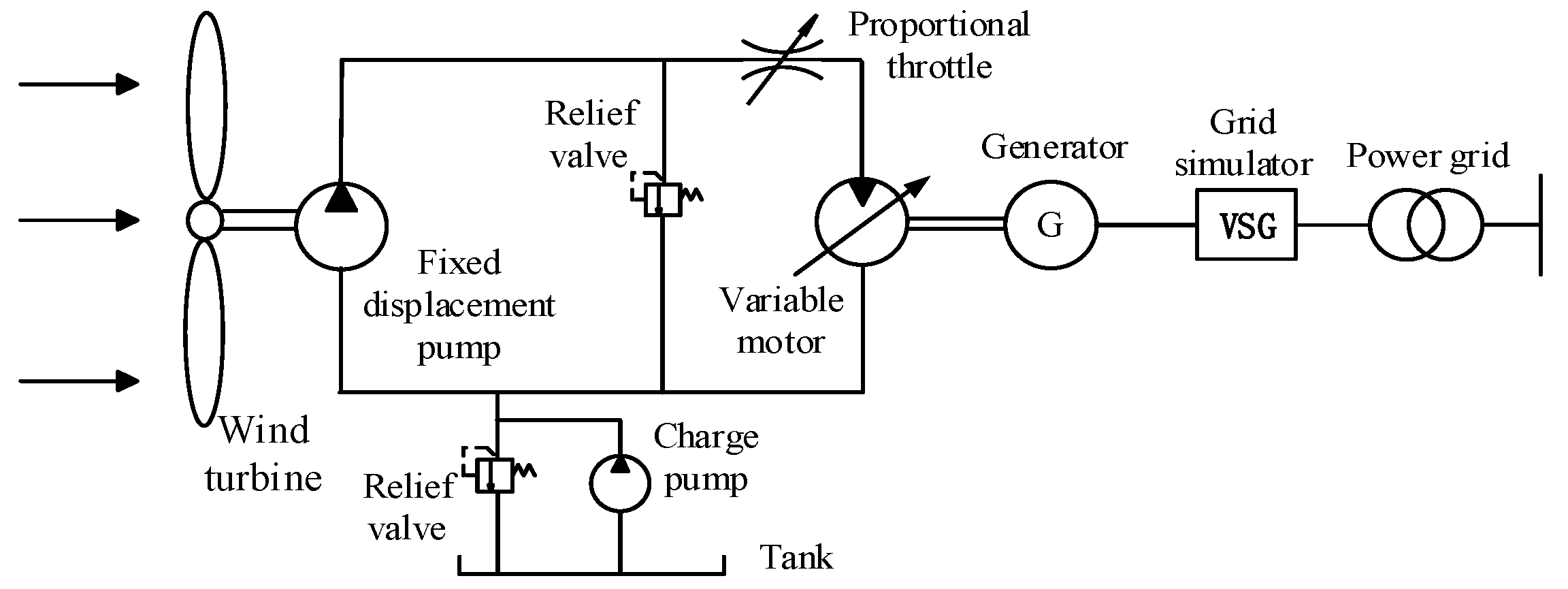
2.1. Working Principle of Hydraulic Wind Turbine

The working principle of the hydraulic wind turbine [29,30] is shown in Figure 1. The main hydraulic drive system consists of a fixed pump–variable motor. When the wind speed changes, the variable motor is stabilized by adjustment of the swash plate angle of the variable motor swash plate. The synchronous generator is driven at the rated speed to generate electricity.
To study the stable operating capacity of the HWT under low voltage conditions, the influence of the generator on the depth of voltage drop of different grids was analyzed, and a mathematical model of each portion of the HWT was established.

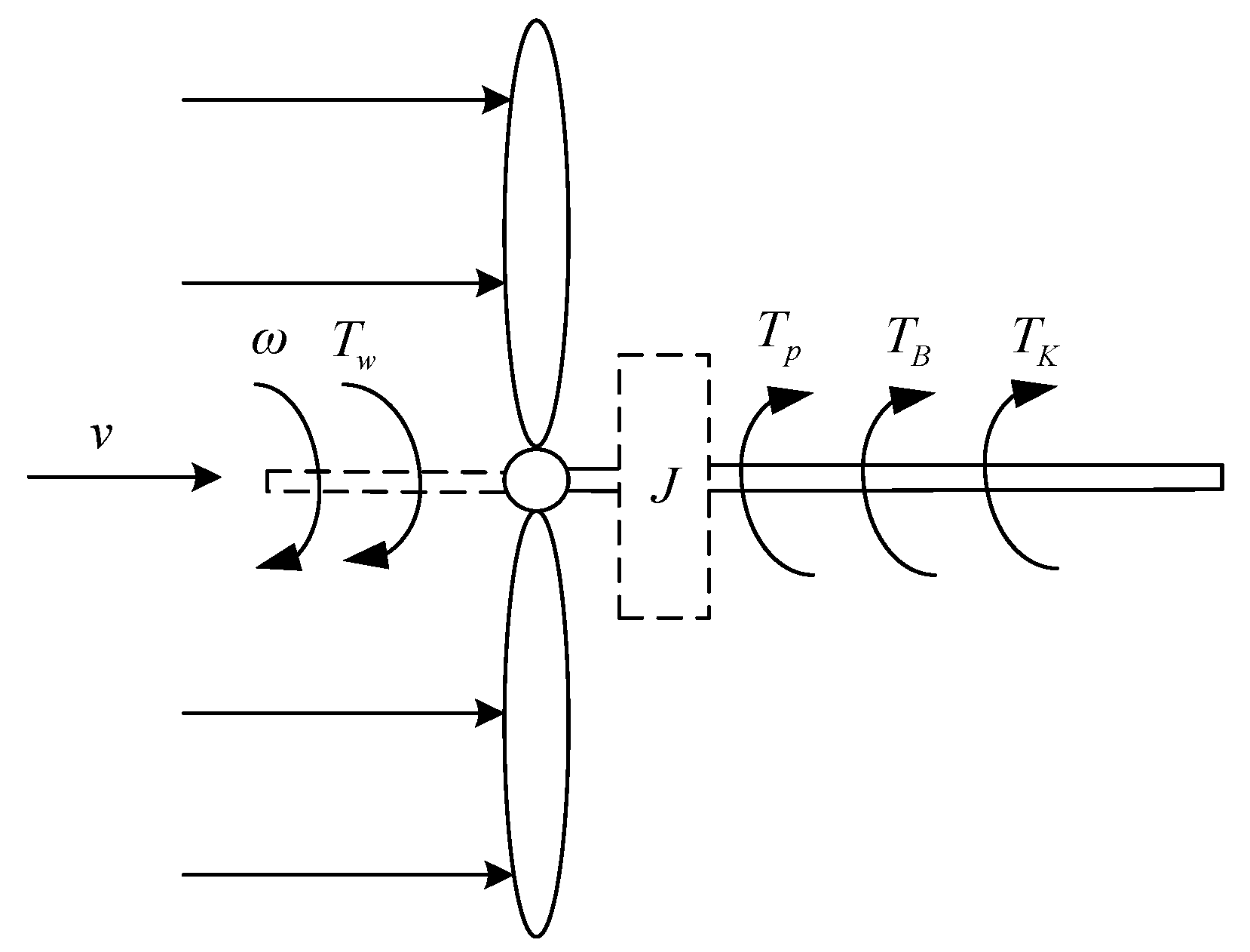
2.2. Wind Turbine Model

To study the energy and torque that a wind turbine obtains from the wind, the wind turbine is usually simplified to a flow tube model, and the wind power obtained by the wind turbine can be expressed as
P t = C p ( λ , β ) ρ A 2 v 3 = 1 2 ρ π R 2 v 3 C p ( λ , β )
where Cp is wind energy utilization factor, λ is tip speed ratio, β is pitch angle, ρ is air density, A is flow area, ν is air velocity, R is wind turbine radius.
The wind energy utilization coefficient C p ( λ , β ) [31,32]:
C P ( λ , β ) = C 1 ( C 2 λ i C 3 β C 4 ) e C 5 λ i + C 6 λ
1 λ i = 1 λ + 0.08 β + 0.0035 β 3 + 1
The coefficients are C1 = 0.5176, C2 = 116, C3 = 0.4, C4 = 5, C5 = 21, and C6 = 0.0068.

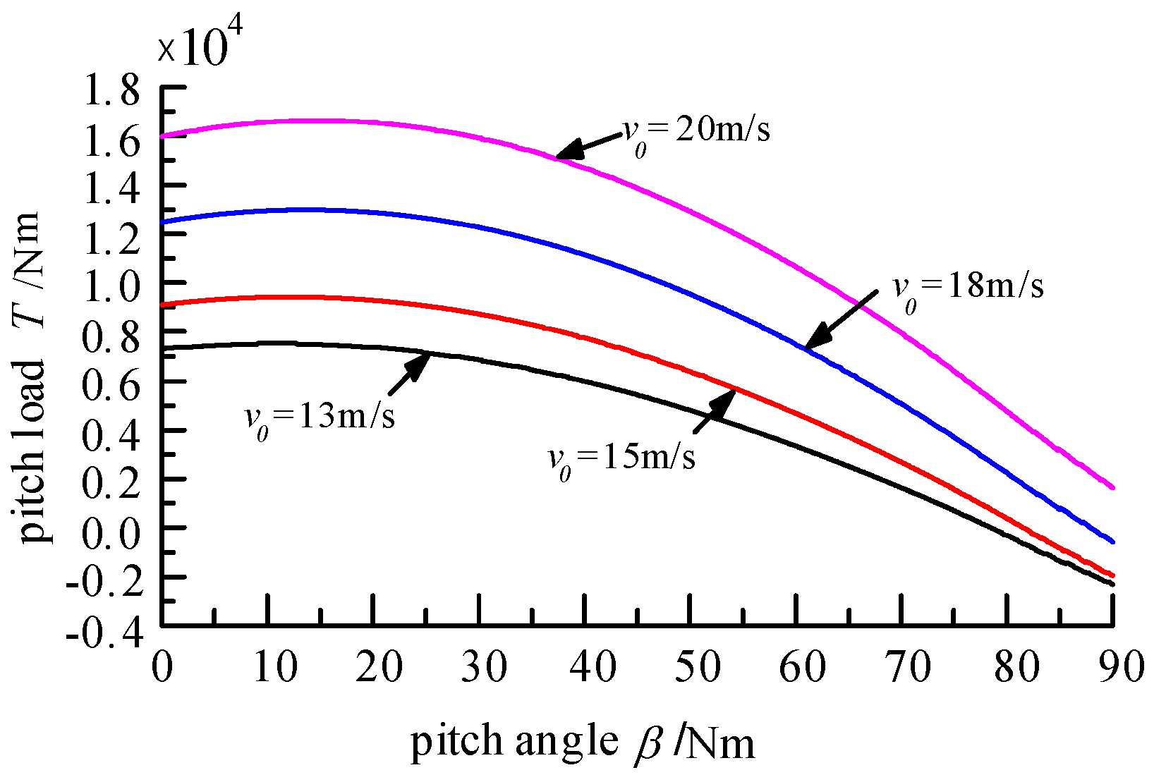
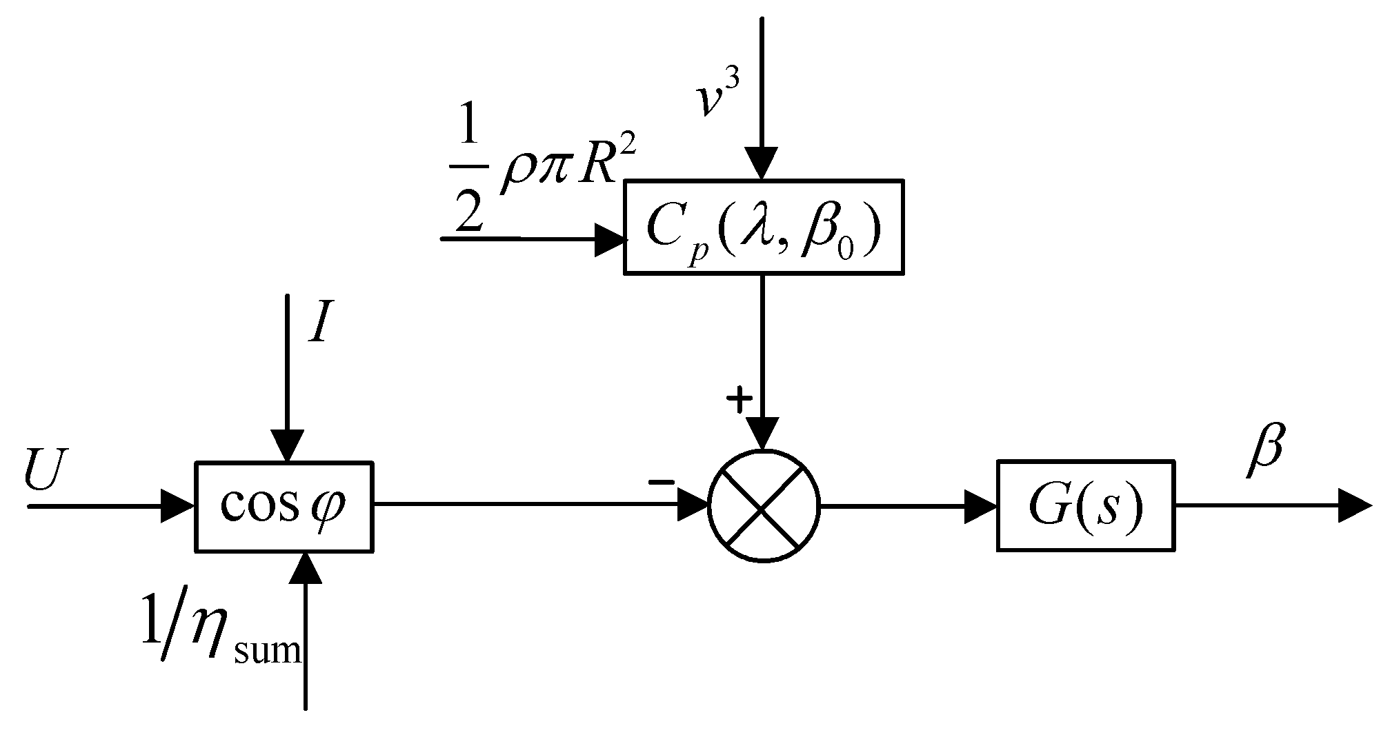
2.3. Pitching System Model

When the wind turbine is in the pitching process, the total torque exerted on the blade can be approximated as
T P 1 = T C + T G + T Z
where TC is torque caused by centrifugal force, TG is torque caused by blade gravity, TZ is blade aerodynamic force.
The pitch load caused by centrifugal force is
T C = 0 r d T C = d T C
The pitch load caused by aerodynamic force is
T Z = 0 R 1 2 ρ V 1 2 c C l 2 + C d 2 Z C s i n ( β + κ ) d r
where Cl is lift coefficient, Cd is resistance coefficient, c is blade chord length at radius r, dr is leaf thickness, V1 is airflow relative to the speed of the leaf, ZC is distance from wind pressure center to pitch axis, κ is the angle between the force and the plane of rotation.
The gravity-induced pitch load is
T G = 0 R g s i n ξ L B s i n φ c o s ψ d m B
where LB is the distance from the leaf quality to the pitch axis, dmB is leaf quality, ψ is angle between LB and BC, φ is angle between BC and rotating surface of the leaf, ξ is angle between the gravity of the leaf and the vertical axis.
There is a certain relationship between variable pitch load and pitch angle. The relationship between Pitch Load and Pitch Angle is obtained as shown in Figure 2.
From Figure 2, it is known that the variable pitch load of the wind turbine varies with the change of Pitch Angle from 0 to 90 at the same wind speed. For example, the variable pitch load of the wind turbine decreases with the increase of pitch angle. In addition, under different wind speed, with the increase of wind speed, the wind turbine is subjected to more variable pitch load.

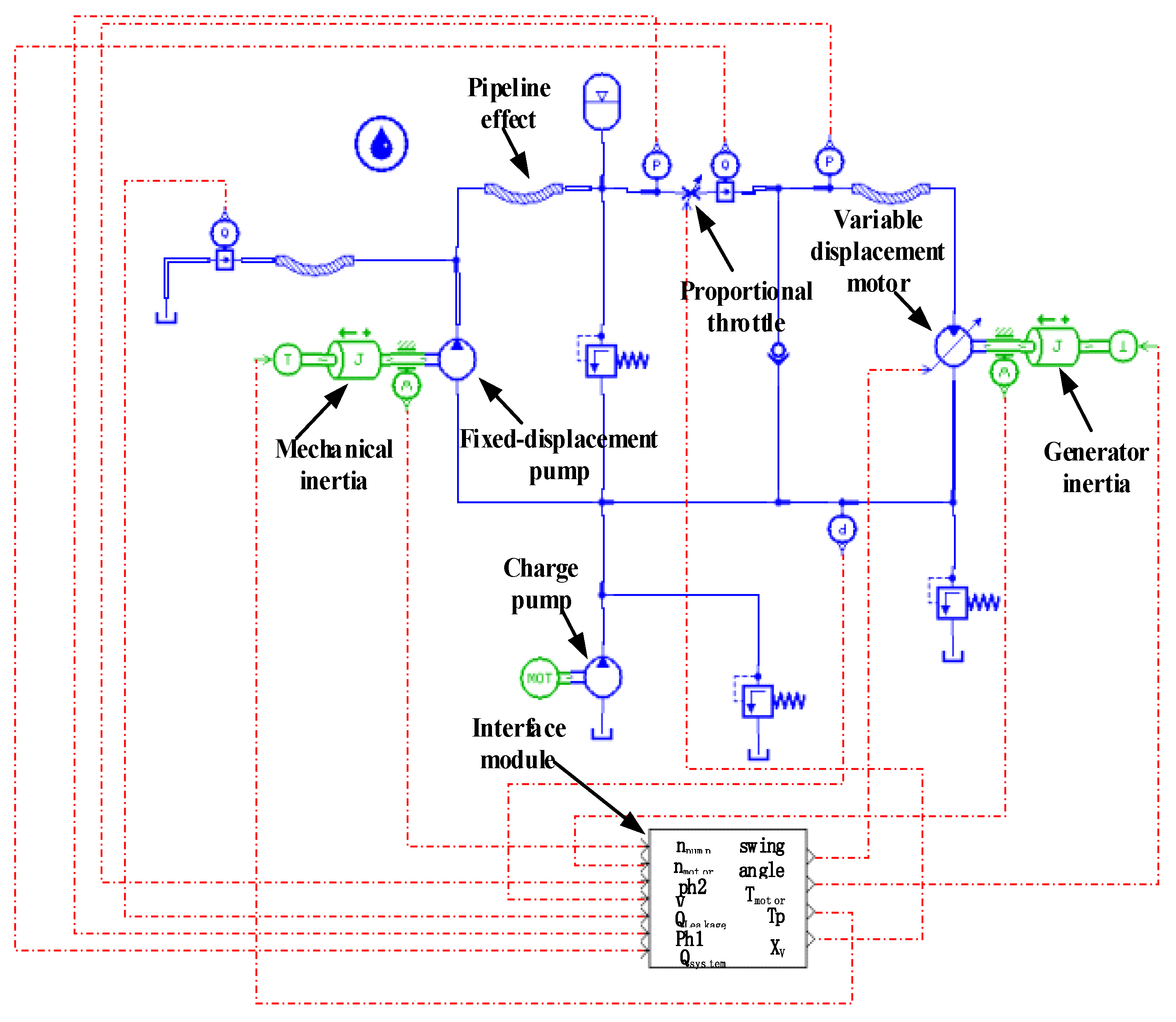
2.4. Hydraulic System Mathematical Model

For ease of analysis, the following assumptions must be made:
(1)
Since the wind turbine is directly connected to the fixed-displacement pump, it is considered that the speed of the wind turbine is the same as the speed of the fixed-displacement pump. That is, the moment of inertia of the wind turbine is converted to the moment of inertia of the fixed-displacement pump.
(2)
The pipeline between the fixed-displacement pump and the variable hydraulic motor is short. Thus, the pressure loss in the pipeline is ignored.
(3)
The bulk modulus of the oil in the high- and low-pressure pipelines is constant, and the pressure is equal.
(4)
There is no pressure shock in the pipeline, the input signal of the proportional throttle valve is small, and no saturation occurs.

2.4.1. The Model of the Fixed-Displacement Pump

The fixed-displacement pump flow continuity equation is
Q p = D p ω p C t p p h 1
where Qp is quantitative pump flow, Dp is quantitative pump displacement, ωp is quantitative pump angular velocity, Ctp is quantitative pump leakage coefficient, ph1 is quantitative pump inlet and outlet pressure differential (pump outlet pressure).
The fixed-displacement pump torque equation is
T p = D p p h 1 η p m
where ηpm is quantitative pump mechanical efficiency.
The fixed-displacement pump torque balance equation is
T w T p = J p d ω p d t + B p ω p + G p θ p
where Tw is wind turbine input torque, Jp is quantitative pump moment of inertia, Bp is quantitative pump damping coefficient, Gp is quantitative pump load spring stiffness, θp is quantitative pump angle.
From (9) and (10), the Equation of state for the fixed-displacement pump is
ω ˙ p = 1 J p ( T w D P p h 1 η p m B p ω p G p θ p ) ( G p 0 )

2.4.2. The Model of the Variable Hydraulic Motor

The variable hydraulic motor flow continuity Equation is
Q m = D m ω m + C t m p h 2
where Qm is variable motor flow, Dm is variable motor displacement, ωm is variable motor angular velocity, Ctm is variable motor leakage coefficient, ph2 is variable motor inlet and outlet pressure difference.
The variable motor displacement Equation is
D m = K m γ
where Km is variable motor displacement gradient, γ is variable motor swash plate angle.
The variable hydraulic motor output torque Equation is
T m = D m p h 2 η m m
where Tm is variable motor output torque, ηmm is variable motor mechanical efficiency.
The variable hydraulic motor torque balance Equation is
T m T e = J m d ω m d t + B m ω m + G m θ m
where Te is electromagnetic torque acting on variable motor, Jm is variable motor moment of inertia, Bm is variable motor damping coefficient, Gm is variable motor load spring stiffness, θm is variable motor angle.
From (13) to (15), the Equation of state of the variable motor is
ω ˙ m = 1 J m ( K m γ p h 2 η m m B m ω m T e G m θ m ) ( G m 0 )

2.4.3. The Model of the Proportional Throttle Valve

The flow Equation of the proportional throttle valve is
Q b = K q X v
where Qb is proportional throttle flow, Xν is proportional throttle opening size, Kq is flow coefficient.

2.4.4. Hydraulic Piping Model

The flow Equation between the fixed-displacement pump and the throttle valve is
Q p Q b = V 01 β e d p h 1 d t
where V01 is quantitative pump to conduit volume between throttle valves.
p ˙ h 1 = β e V 01 ( D p ω p K q X v C t p p h 1 )
The flow Equation between the throttle valve and the variable motor is
Q b Q m = V 02 β e d p h 2 d t
where V02 is pipe volume from throttle to variable motor.
The state Equation of the throttle valve to the variable motor high pressure pipeline is
p ˙ h 2 = β e V 02 ( K q X V K m γ ω m C t m p h 2 )

2.4.5. Hydraulic System Overall Model

The following state space expression combines Equations (9), (14), (17) and (19).
[ ω ˙ P p ˙ h 1 ω ˙ m p ˙ h 2 ] = [ B p J p D p J p η m p 0 0 β e D p V 01 β e C t p V 01 0 0 0 0 B m J m 0 0 0 0 β e C t m V 02 ] [ ω P p h 1 ω m p h 2 ] + [ 1 J p 0 0 0 0 β e K q V 01 0 0 0 0 1 J m K m η m m J m p h 2 0 K q β e V 02 0 β e K m ω m V 02 ] [ T w X v T e γ ]

3. Research on LVRT Energy Regulation

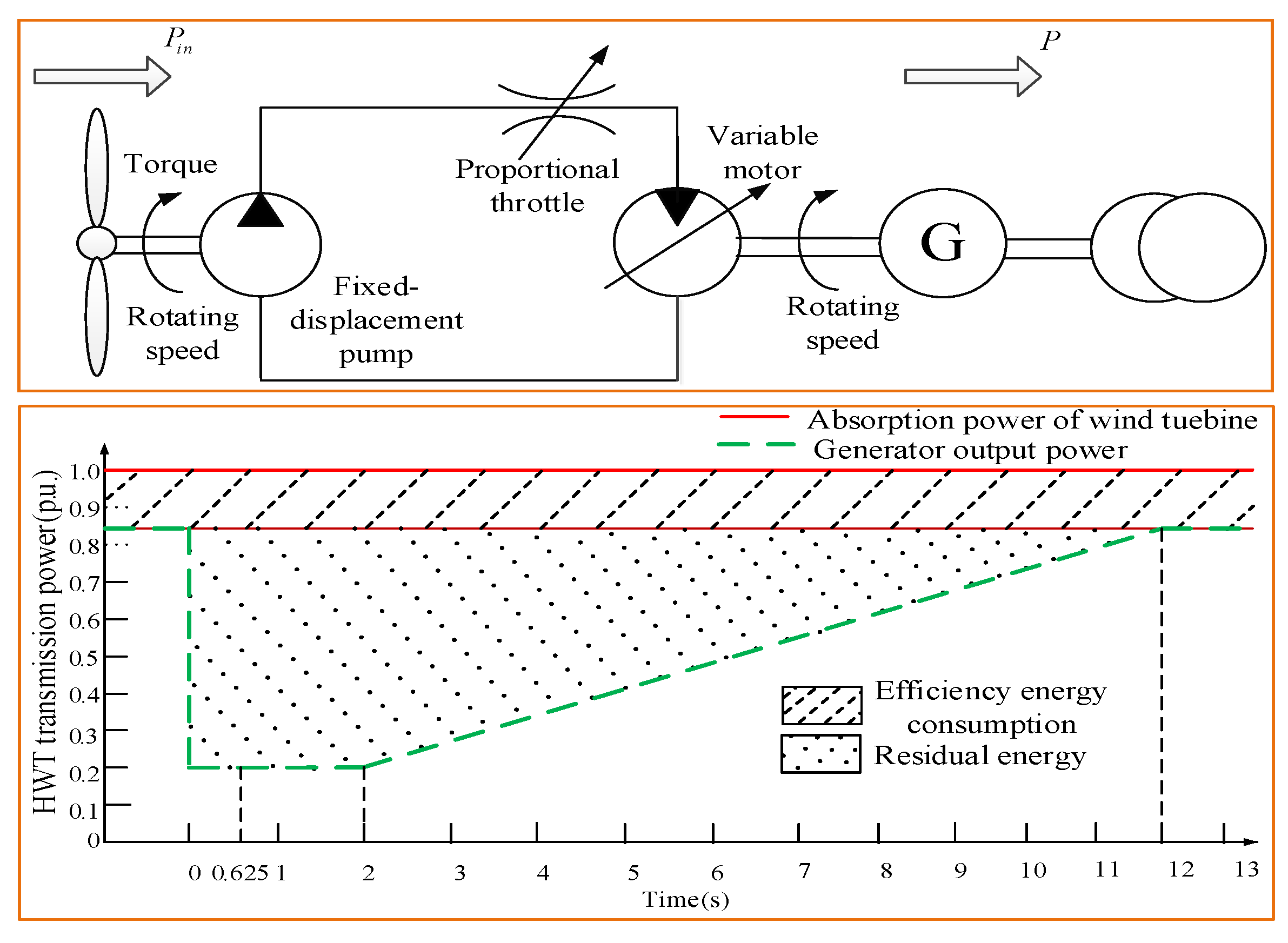
3.1. Analysis of LVRT Energy Transfer Mechanism

3.1.1. LVRT Residual Energy Generation Mechanism

In the LVRT process of the HWT, the voltage of the grid connection point drops instantaneously. To avoid the generator burning out due to overcurrent, it is necessary to reduce the output power of the generator. Combined with the LVRT control requirements and the energy transfer principle of the HWT, the energy flow diagram during the LVRT is obtained, as shown in Figure 3.
It can be seen from Figure 2 that, during LVRT, the residual energy Ws can be expressed as
W s = ( P t ( t ) P g ( t ) ) d t
where P g ( t ) is active power output from the generator.
The active power output from the generator is
P g ( t ) = E U X d s i n δ + ( 1 X q 1 X d ) U 2 2 s i n 2 δ
where E is excitation potential, U is power voltage, Xd is straight axis synchronous reactance, Xq is cross-axis synchronous reactance, δ is power angle.
It can be seen from the above analysis that the storage and dissipation of residual energy is a key issue in the LVRT process control.

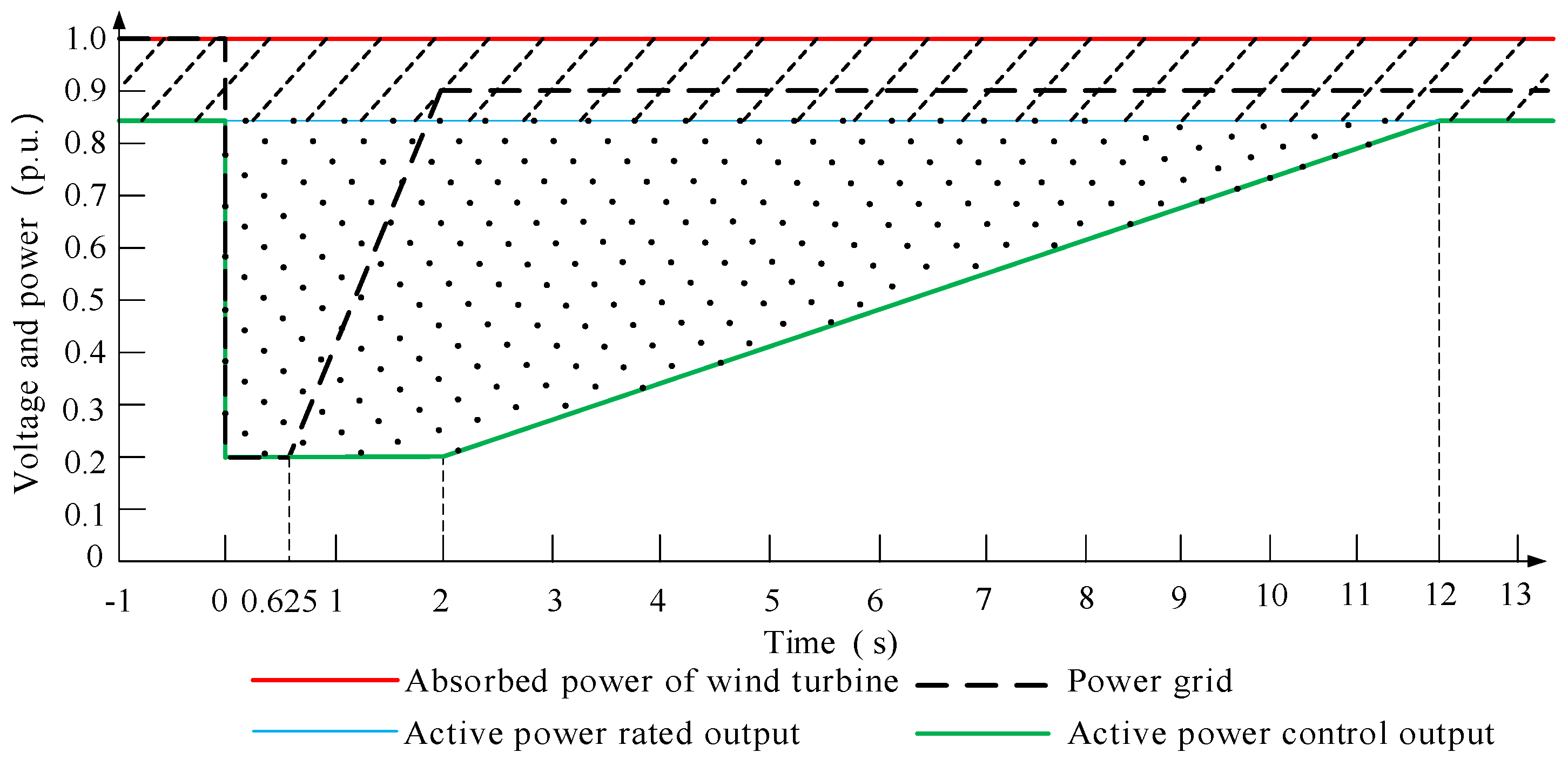
3.1.2. Energy Transmission Law of LVRT

Based on the grid-connected technical specifications of wind turbines in China [1], the low-voltage traversal energy transmission law of HWT is analyzed. The energy transmission law for HWT in particular is shown in Figure 4.
During LVRT, the HWT’s regulation of the remaining energy is divided into three phases: the primary phase, the transition phase, and the recovery phase.
In the primary stage (t = 0 s~0.625 s), the grid voltage drops rapidly, and the output power of the generator set is required to be quickly adjusted to consume the remaining energy of the HWT.
In the transition phase (t = 0.625 s~2 s), the grid voltage is gradually recovered, and the generator set is required to output low power to permit inertial energy storage and recover the energy of the HWT.
In the recovery stage (t = 2 s~12 s), the power grid is cut off, and the HWT is required to gradually release the stored energy, so that the HWT output power is gradually recovered at a rate of 10% of rated power per second.

3.2. LVRT Energy Layered Control

Based on the mechanism of residual energy transfer during low voltage power transmission, an energy hierarchical control strategy is proposed, in which the residual energy is regulated by adjusting the pitch angle to reduce the absorption of wind power, the inertia energy storage of the wind turbine and the energy consumption of the proportional throttle valve. The main purpose of adjusting the pitch angle is to reduce the input of energy in the process of LVRT. Adjusting the variable motor swing angle is to store the surplus energy into the wind turbine and change it into kinetic energy. The throttle valve opening is adjusted primarily to dissipate excess energy in the form of heat during LVRT. In this article, they are called top-level control, mid-level control, and underlying control.

3.2.1. Top-Level Control

During LVRT, the residual energy of the HWT is reduced from the source by adjusting the pitch angle. It can be seen from Equation (2) that the strategy of pitching and abandoning wind substantially reduces the absorbed power of the wind turbine by increasing the pitch angle, thereby reducing the residual energy during LVRT. The pitch angle and the pitch angle control law are shown in Figure 5.
According to the principle of balance between wind power and motor output power, the controller of pitch angle can be obtained according to block diagram as follows:
β = ( 1 2 ρ π R 2 v 3 C p ( λ , β ) U I c o s φ η sum ) G ( s )
when the top-level control method is used, the wind power absorbed is larger than the output power of the motor, so the wind power absorbed from the source is reduced by adjusting the pitch angle. When the voltage drops, the active power of the generator is reduced, and thus the residual power is increased. In this case, it is necessary to adjust the pitch angle so that the absorption power of the wind turbine is equal to the active power of the generator.

3.2.2. Mid-Level Control

During the LVRT process, the hydraulic system pressure is reduced by adjusting the variable hydraulic motor swash plate angle to reduce the load torque of the wind turbine, and the residual energy of the wind turbine is converted into kinetic energy by using the considerable inertia of the wind turbine. The energy stored by the wind turbine is fed back to the grid.
Equations (8), (12) and (13) show that when only the variable hydraulic motor swash plate angle participates in LVRT control, ph = ph1 = ph2, and the transfer function of the system pressure with respect to the variable motor swash plate angle is
p h γ = K m ω m / C t 1 + V 0 β e C t s
where Ct is total leakage coefficient, Ct = Ctp + Ctm.
The Motor Swing Angle Controller is
γ = ( 1 + V 0 β e C t s ) p h K m ω m / C t
In the mid-level control method, the pressure of the system is reduced by adjusting the swing angle of the variable motor, so the power of the grid is reduced. And the specific angle of adjusting variable motor swing angle is determined by the above controller.
The hydraulic load torque of the wind turbine can be expressed as
T p h = D p p h
From Equations (27) and (28), the transfer function between the hydraulic load torque of the wind turbine and the swash plate angle of the variable hydraulic motor is found to be
T p h γ = D p K m ω m / C t 1 + V 0 β e C t s
The dynamic force analysis of the wind turbine is shown in Figure 6.
Normally, the viscous moment of the wind turbine main shaft TB and the elastic moment Tk are small, in which case the wind turbine dynamic equation can be simplified to the following:
J d ω p d t = T w T p
The remaining energy of the HWT is converted into kinetic energy of the wind turbine. The energy Equation is
1 2 J ω p t 2 1 2 J ω N 2 = W i n
where ωpt is speed after the wind turbine is stored, U is power voltage, ωN is the speed before the wind turbine is stored (usually the rated speed), Win is Total inertial energy storage value of wind turbines.
According to the above analysis, middle layer control actually reduces the energy transmitted by the HWT to the grid by adjusting the hydraulic motor swash plate angle and converting the remaining energy of the HWT into the kinetic energy of the wind turbine.

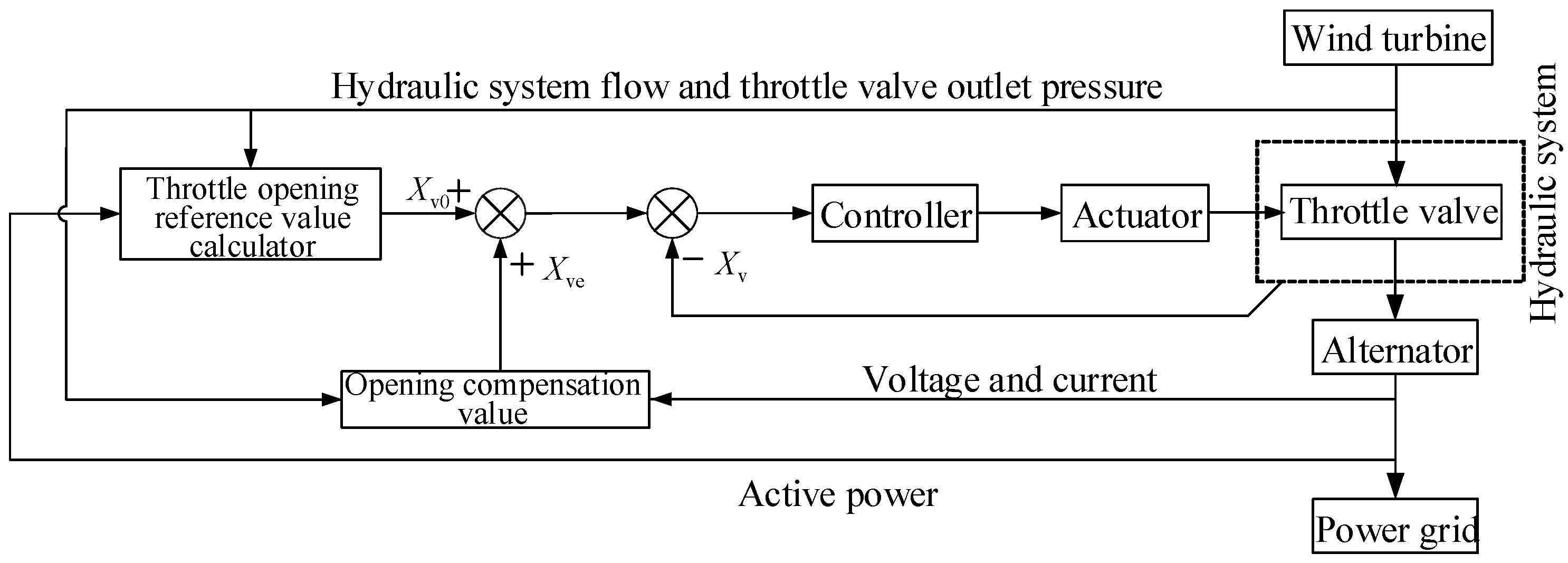
3.2.3. Underlying Control

In the bottom layer control, the variable motor inlet pressure is adjusted by the proportional throttle adjustment valve, and the remaining energy of the HWT is converted into heat energy that is quickly dissipated, allowing the output energy of the HWT to be quickly adjusted. The energy dissipated by the proportional throttle valve during the control process is
W b = Q b ( p h 1 p h 2 ) d t
The remaining energy of the HWT during LVRT is
Δ P = Δ W Δ t = Q p p h 1 U I c o s φ η g
where ηg is total efficiency of the generator, cosφ is power coefficient.
The first term on the right side of Equation (31) is the input energy of the hydraulic system dosing pump, and the second term is the active power output by the generator.
The proportional throttle valve opening reference value can be expressed as
X v 0 = Δ P K q p L
where pL is proportional throttle valve differential pressure.
The throttle valve opening controller is:
X v 0 = Q P P h 1 U I c o s φ η g K q P L
When the underlying control method is used, the corresponding residual energy can be converted into heat energy by adjusting the size of the throttle valve opening. The specific size of the throttle opening is determined by the above controller. When the voltage drops, the active power of the generator decreases, so that the difference between the power of the hydraulic system and the active power of the generator is increased. The residual power is dissipated as heat through a throttle valve.
The proportional throttle opening reference value is given as a block diagram, shown in Figure 7.
This is the fastest control method in the LVRT process. However, during the regulation process, it will cause the temperature of the hydraulic system to rise rapidly. Therefore, the throttle valve opening and the system temperature rise should be considered in the control process.

3.3. Energy Stratification Control Law Planning

There are multiple input and output variables in energy stratification control. To ensure safety, save energy, and stabilize the performance of HWT control, it is necessary to establish a multiobjective coordination adjustment mechanism. A sequential quadratic programming algorithm is used to constrain the multiobjective coordination mechanism.

3.3.1. Selecting the Target of Optimization

In the LVRT process, energy regulation of the HWT is achieved by controlling the wind turbine pitch angle, the variable motor swash plate angle and the proportional throttle opening variable. Therefore, three control variables must be optimized.
u = ( u 1 u 2 u 3 ) = ( β γ X V )

3.3.2. Determining the Optimization Goal

During the LVRT process, the specific goal with regard to optimization is minimizing the absorbed wind power of wind turbine by adjusting the pitch angle, maximizing the inertial energy storage of the wind turbine, and minimizing the energy dissipation of the proportional throttle valve. That is, to ensure rapid adjustment of HWT power, the inertial energy storage of the wind turbine is increased as much as possible, and the throttling heat is reduced. The energy dissipation of the inertial energy storage, the pitching and abandonment of the wind turbine, and the energy dissipation of the proportional throttle valve are measured by ωpt, Cp and Pb respectively, and the energy dissipation objective function can be expressed as J1, J2 and J3 respectively.
min J 1 = ( ω N ω p t ) 2
min J 2 = ( 1 C p C p m a x 2 )
min J 3 = ( P b P b m a x 2 )
In hierarchical control, the three objective functions above are combined by a linear weighting method to simultaneously satisfy all of the requirements. In this way, the objective function is obtained as follows:
min J O = w 1 J 1 + w 2 J 2 + w 3 J 3
where w1, w2, and w3 are linear weight coefficients satisfying the following conditions: w1, w2, w3 > 0 and w1 + w2 + w3 = 1.

3.3.3. Construction Constraints

In the multiobjective coordinated control process of the HWT, a sequential quadratic programming algorithm is used to constrain the multiobjective cooperative control for each parameter. The constraints are as follows:
(1) Constraints and conditions for top-level paddle control:
Pitch mechanism running smoothly
β ˙ ( t ) β ˙ m a x
Pitch mechanism responding quickly
β ˙ min β ˙ ( t )
Pitch trajectory operation
0 < β ( t ) < 90
(2) Constraints corresponding to inertial energy storage control of mid-level wind turbines:
Prevention of excessive acceleration of wind turbines
ω p ω m a x
Ensuring that the variable motor runs at a steady speed
ω m Δ ω m ω m ω m + Δ ω m
Variable motor swash plate angle trajectory
γ m a x m i n
(3) Constraints corresponding to the underlying proportional throttling dissipation control:
Ensuring that all remaining energy is completely dissipated, preventing generator energy imbalance and current overload
W b W s W i n
Preventing excessively high hydraulic system fluid temperature
W b W m a x
Reasonable operation of proportional throttle opening trajectory
X ν m a x m i n
Proportional throttle valve throttle dissipation to maintain system pressure safety limit
{ p h 1 p h m a x p h 2 p h m a x
In summary, the sequential quadratic programming algorithm is used to control energy stratification of the HWT. The constraint condition is
{ β ˙ min β ˙ ( t ) β ˙ max 0 < β ( t ) < 90 ω p ω max ω m Δ ω m ω m ω m + Δ ω m γ min < γ < γ max W s W i n W b W max X min < X ν < X max p h 1 p h max p h 2 p h max
The above problem is solved using the Optimization Toolbox in MATLAB.
For this system, the constraint condition is:
{ 6 ° / s β ˙ ( t ) 10 ° / s 0 < β ( t ) < 90 ω p 20 r / min ( 1500 6 ) r / min ω m ( 1500 + 6 ) r / min 0 ° < γ < 15 ° W s W i n W b W max 0 < X ν < 10 mm p h 1 25 MPa p h 2 25 MPa

4. Test and Simulation

Using MATLAB/Simulink and AMESim simulation software, a LVRT simulation platform for HWT was built. The simulation model of the main hydraulic drive system of the HWT is shown in Figure 8. The parameters of each component are shown in Table 1.

4.1. Simulation Research on the Law of Residual Energy Generation of HWT

Using the traditional control strategy, that is, without the addition of pitch control and throttle valve opening control, the energy input and output characteristics of the HWT were simulated. Since the two-phase voltage drop and the single-phase voltage drop are both asymmetric voltage drops, this paper mainly focuses on the low-voltage case of single-phase voltage drop and three-phase voltage drop, and a grid voltage single-phase drop of 80% and a three-phase drop of 20% were simulated. The simulation results of the unit’s active power and variable motor speed are shown below in Figure 9.
It can be seen from Figure 8 that using the traditional control strategy, the output power of the HWT fluctuates greatly, excessive residual energy is generated in the HWT, and a significant amount of time is required for the active power of the HWT to return to normal. It can be seen from Figure 9b,d that when the maximum value of the variable motor speed fluctuation reaches 2400 r/min, the HWT is off-grid.

4.2. Simulation Study on HWT Energy Regulation

Based on analysis of the simulation on the residual energy of the aforementioned HWT, it is found that excessive residual energy is generated in the HWT during LVRT, affecting the stability of the HWT. The influence of the method of energy regulation on the system is analyzed with regard to three factors: pitch angle control of the HWT, variable motor swash plate angle control, and throttle opening control.

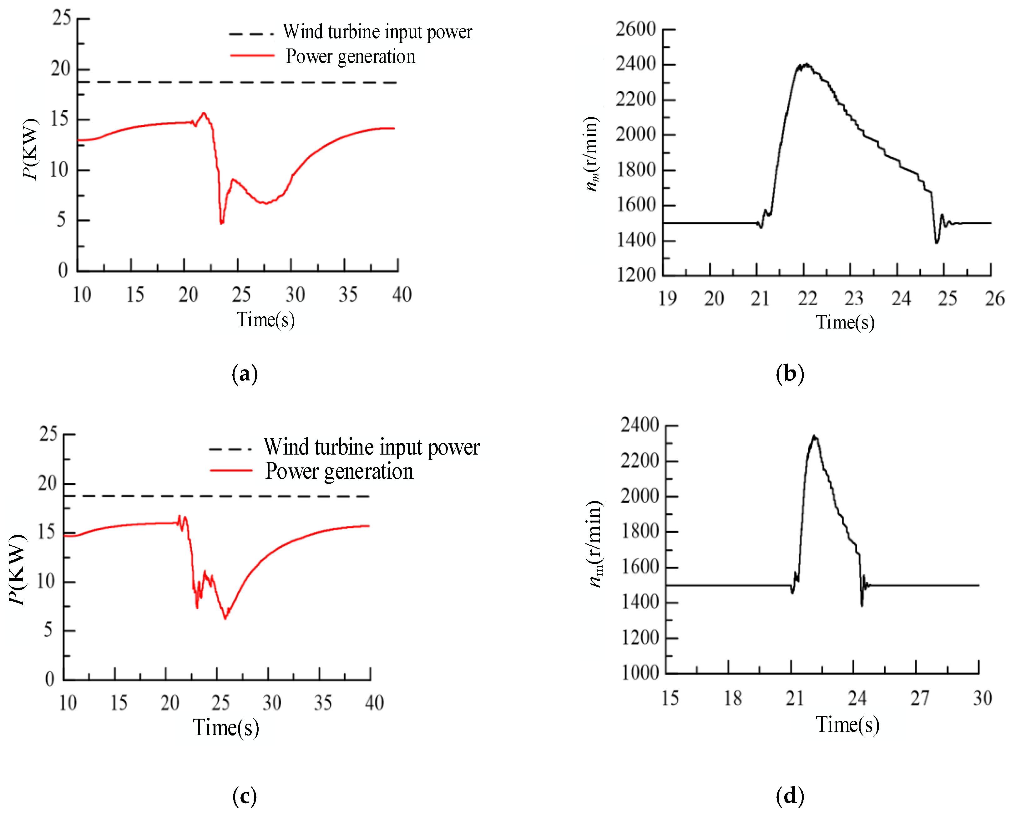
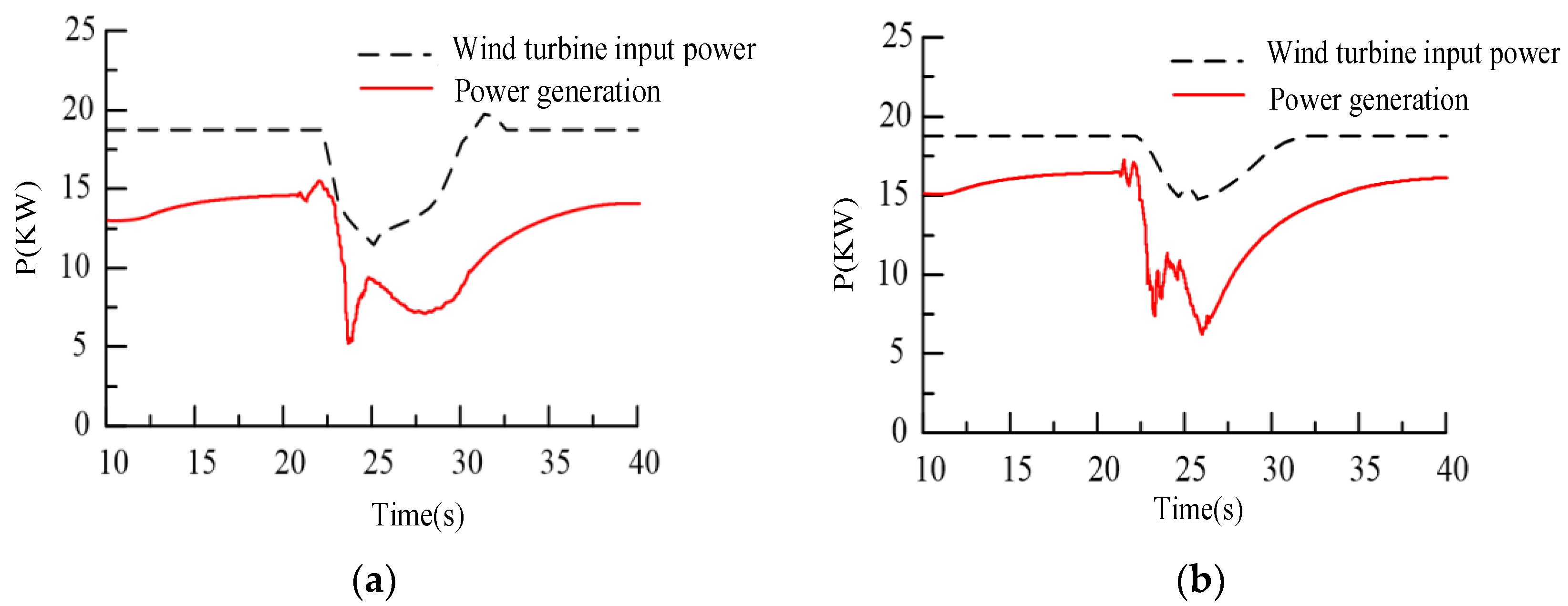
4.2.1. Simulation Study on Top-Level Control Effect of Pitching and Abandoning Wind Power

In the LVRT process, a single-phase voltage drop of 80% and a three-phase drop of 20% occur. Wind and control of the pitch were simulated. The results of the simulation are shown in Figure 10.
It can be seen from the results of the simulation that, when the grid voltage drops and the pitch angle control law is implemented, the input energy of the HWT matches the trends of power generation, which fundamentally reduces the production of residual energy.

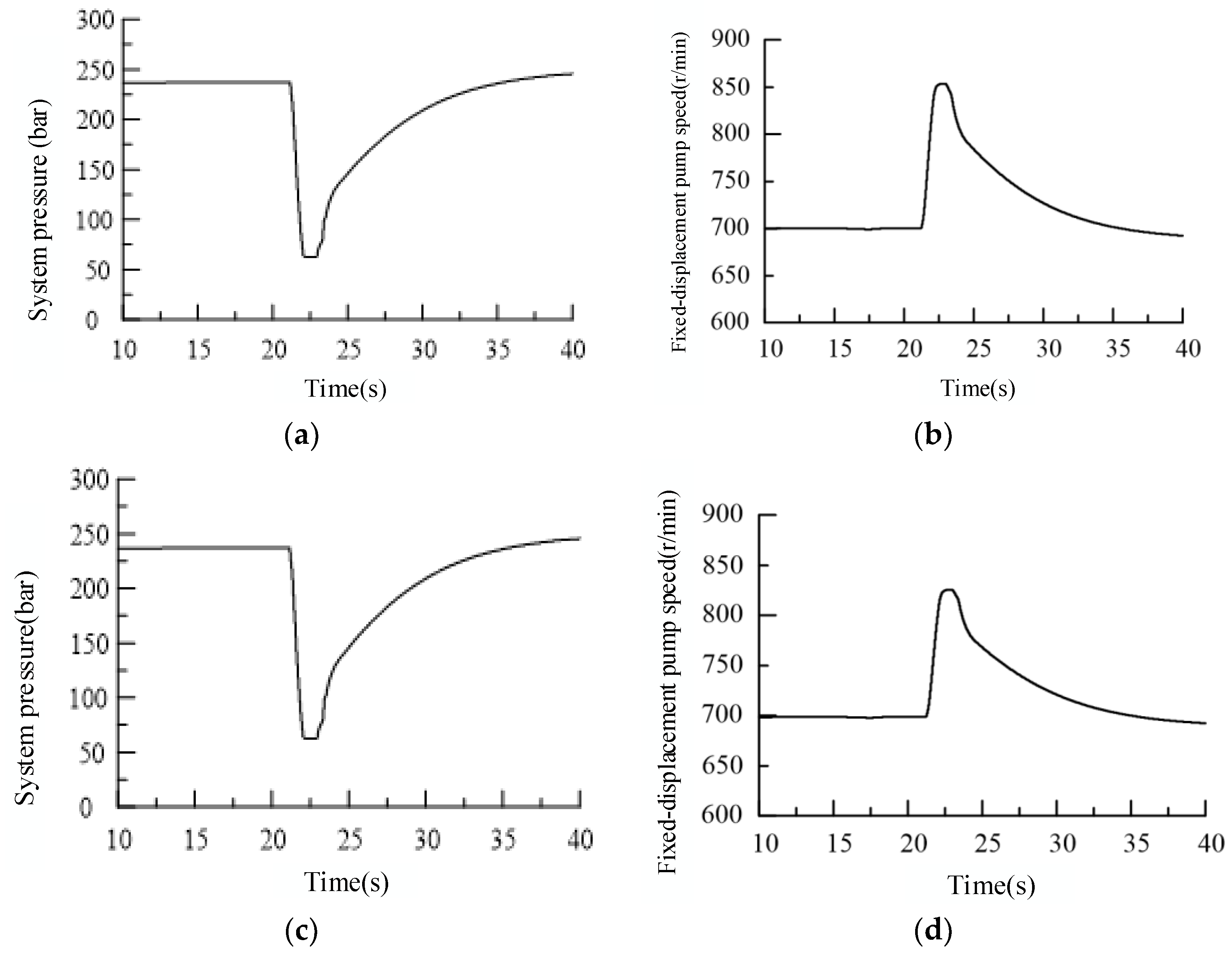
4.2.2. Simulation Study on Mid-Level Control Effect of Adjusting Variable Motor Swash Plate Angle

Using the simulation platform for the case of a grid voltage single-phase drop of 80% and a three-phase voltage drop of 20%, the hydraulic system pressure and the quantitative pump speed of the HWT were simulated to study the variable motor swash plate angle on the ability to control the LVRT process. This simulation is illustrated in Figure 11.
It can be seen from Figure 10 that after the variable motor swash plate angle control law is incorporated, the fixed-displacement pump speed (wind turbine speed) accelerates significantly following the voltage drop. This outcome permits a portion of the input energy to be converted into kinetic energy of the wind turbine, reducing the energy input of the HWT. This process allows for stable operation of the HWT under LVRT conditions.

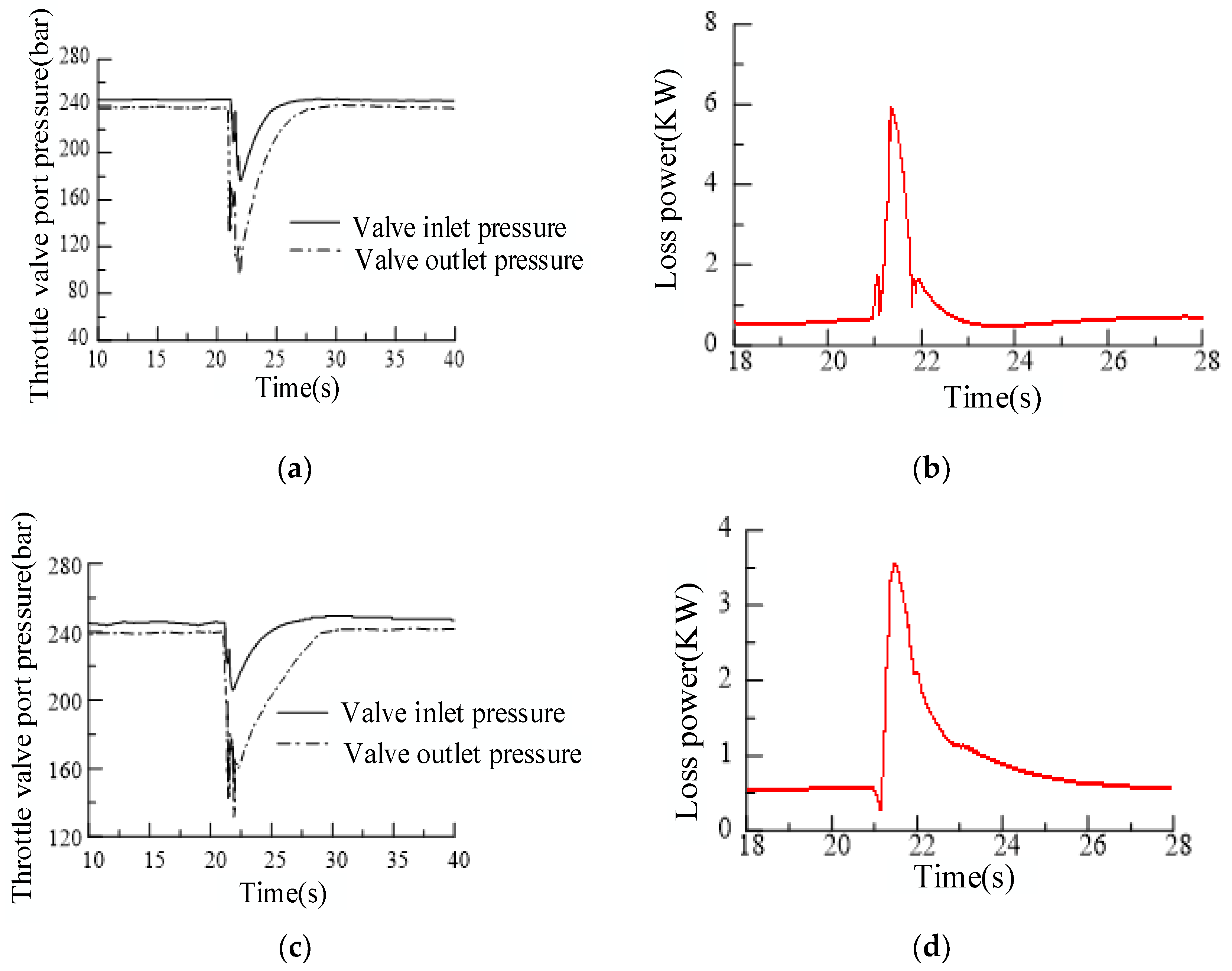
4.2.3. Simulation Study on Underlying Control Effect of Adjusting the Throttle Valve Opening

The control effect of the throttle valve was simulated under the two conditions of grid voltage drop during the LVRT process: a single-phase drop of 80% and a three-phase drop of 20%. These are illustrated in Figure 12.
It can be seen from Figure 12 that when the grid voltage falls, the inlet and outlet pressures of the throttle valve clearly decrease, and the pressure difference gradually increases. When the grid voltage is restored, the pressure gradually rises, and the pressure difference gradually decreases. In the process, the throttle valve’s power loss varies with the pressure difference between the inlet and outlet of the throttle valve. The energy loss of the throttle valve essentially conforms to the remaining energy of the HWT in the operating condition. It can, in a timely manner, dissipate the residual energy caused by the slow speed of the wind turbine of the HWT, as well as relieve the energy impact resulting from dynamic mismatch between the input power of the wind turbine and the power generation of the hydraulic system. Furthermore, it dissipates the remaining energy of the HWT through the throttle valve.

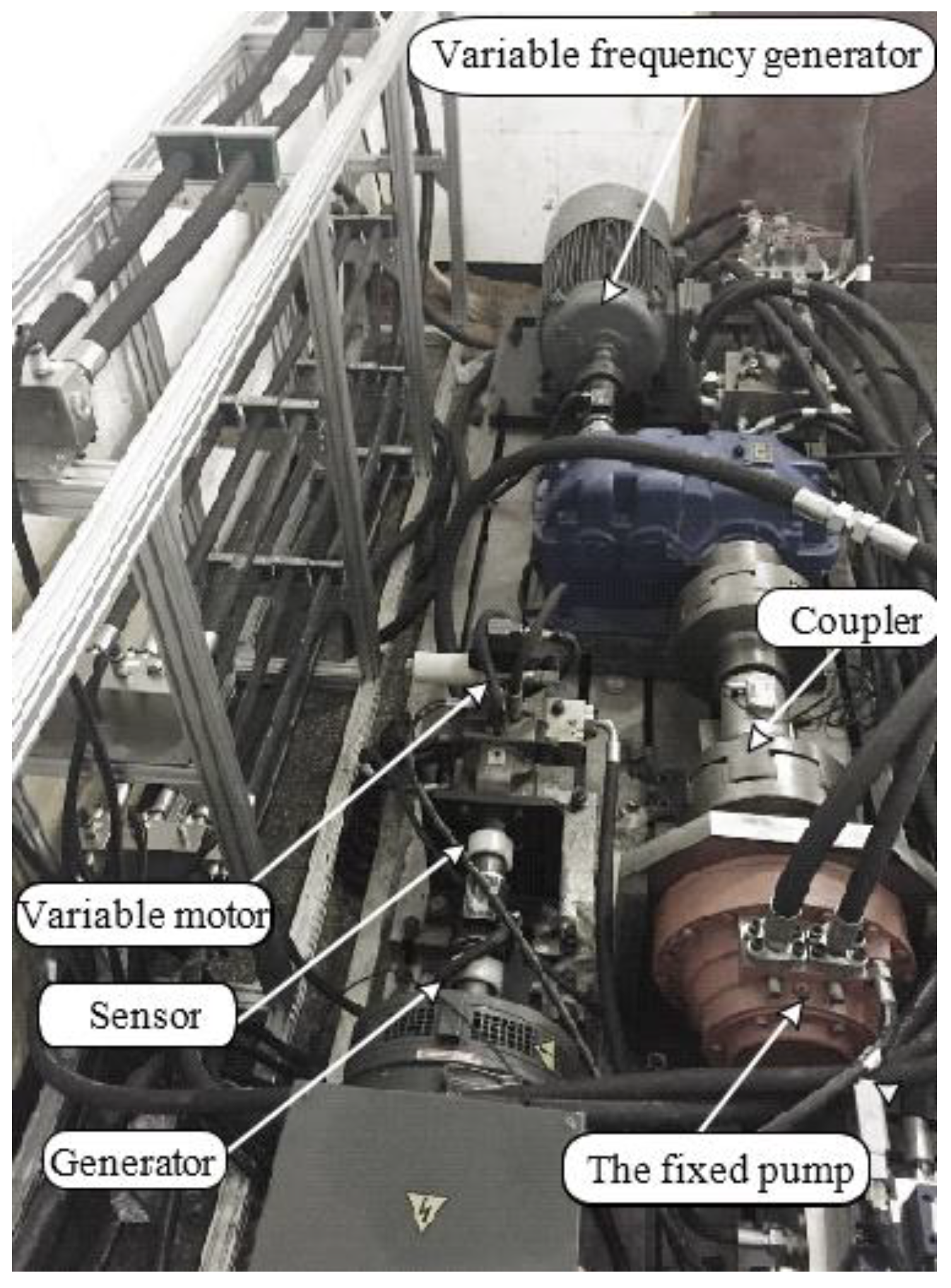
4.3. Experimental Research

The proposed LVRT control law was studied using a semiphysical simulation test platform of a 30 kVA hydraulic wind turbine. The test platform consisted of a wind turbine simulation system, a main hydraulic drive system, and a grid-connected control system. hydraulic wind turbine under various working conditions as well as different grid fault conditions. The physical layout of the test platform is shown in Figure 13.
The control algorithm of the proposed control strategy is programmed in Matlab/Simulink, and Dspace is used to control the rotational speed of the fixed-displacement pump, the throttle opening, and the swing angle of the motor. The simulation and experimental study of the HWT under LVRT conditions of three-phase voltage drop by 20% and single-phase voltage drop by 80% are carried out.

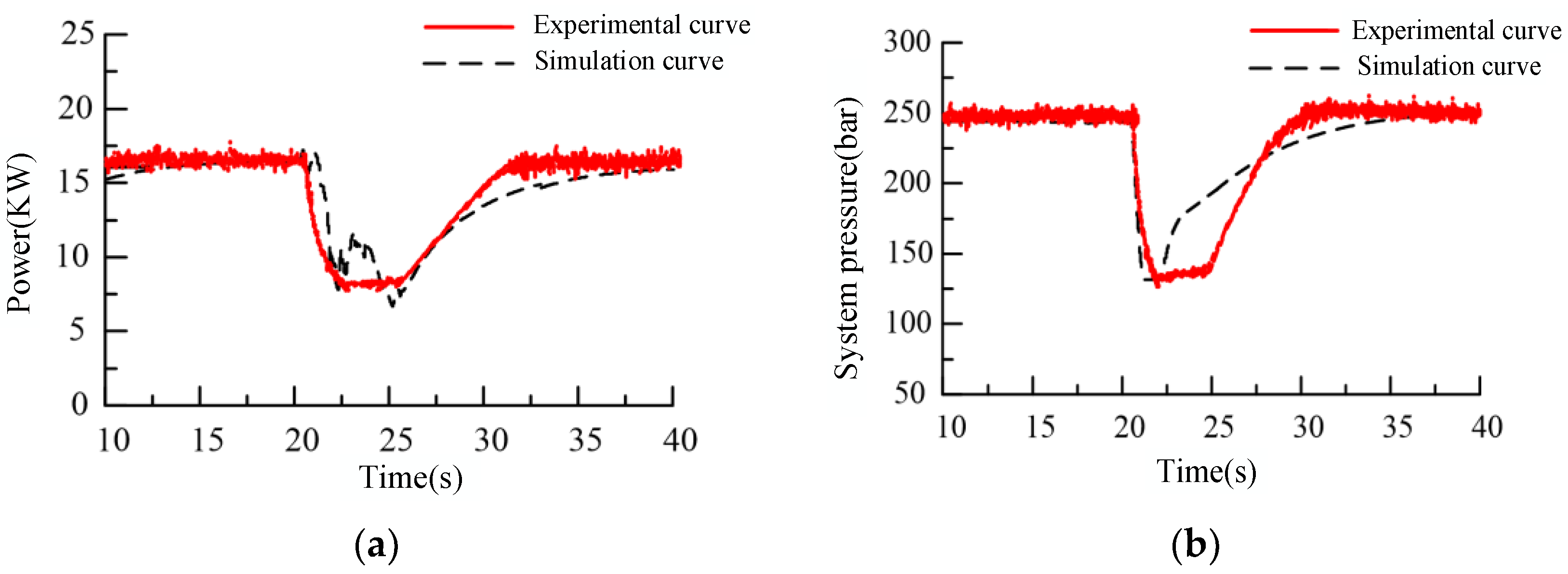
4.3.1. Joint Simulation and Experiment of Three-Phase Voltage Drop of 20%

When the three-phase voltage drops, the energy impact of the HWT is the most serious. In the course of the experiment, the grid simulator is used to set the grid voltage drop manually. The setting is as follows: The grid voltage three-phase voltage drop begins at 10 s, the drop depth is 20%, and the drop duration is 0.5 s. The active power, system pressure, wind turbine speed, motor torque, and other parameters are collected. Test curves of the control effects of three-phase drop of the grid voltage are shown in Figure 14.

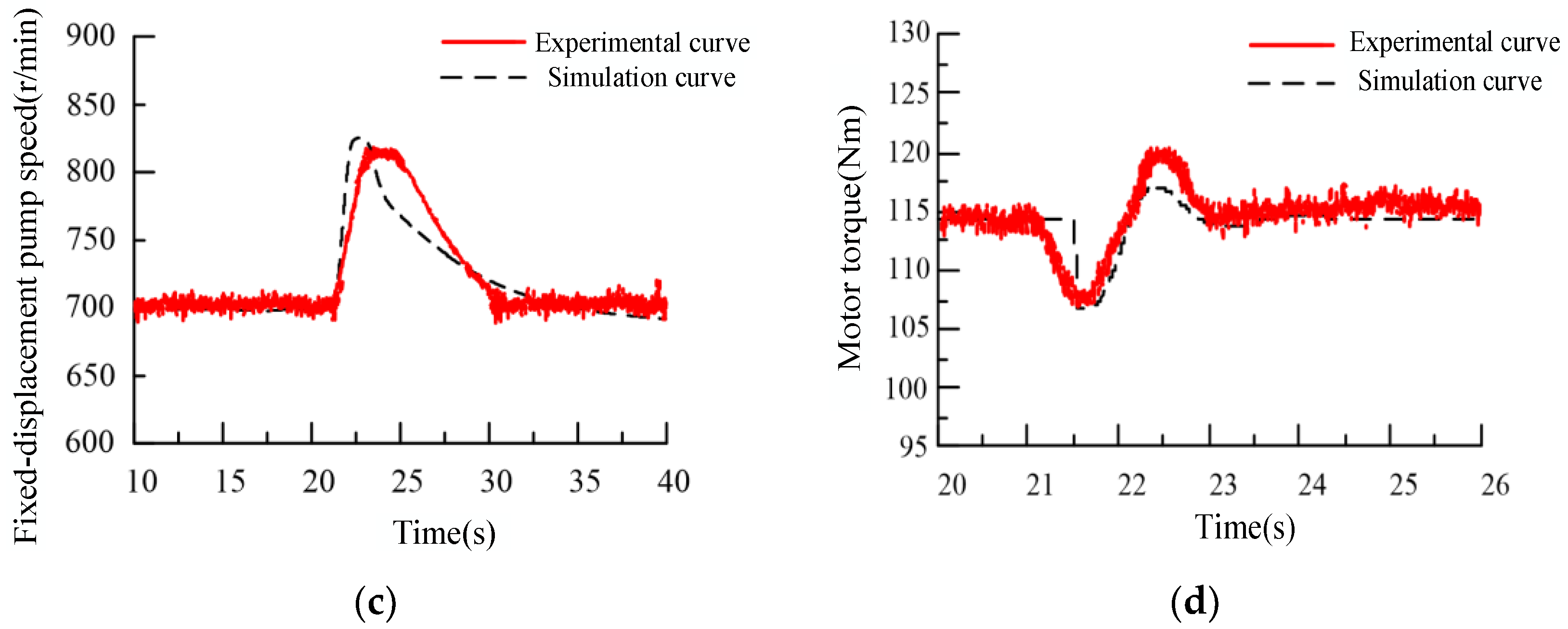
4.3.2. Joint Simulation and Experiment of Single-Phase Voltage Drop of 80%

The single-phase voltage drop fault is a kind of asymmetric network fault. It is of great engineering value to study the regulation effect of low voltage traversal control law on single-phase voltage drop fault. During the experiment, the grid voltage sags were manually set with the help of the grid simulator. The setting is as follows: The grid voltage a phase starts to drop from 10 s, the depth of drop is 80%, and the time of drop lasts 0.5 s. The system parameters, such as active power, system pressure, wind turbine speed and motor Torque, are collected in the course of low voltage crossing. Test curves of the control effects of single-phase drop of the grid voltage are shown in Figure 15.

4.3.3. Result

The experimental results show that when the three-phase voltage drops by 20% and the single-phase voltage drops by 80%, the active power output curve of the HWT basically accords with the trend of the simulation results, which verifies the effectiveness of the active power output control in the simulation experiment. The pressure curve of the hydraulic system of the HWT decreases obviously after the voltage drops, then it starts to rise after the minimum value of 3 s. The speed curve of the fixed-displacement pump of the HWT has obviously increased after the voltage drop, and gradually returned to normal state after the peak value has been maintained for a period of time. The changing trend of the actual curve of the fixed-displacement pump speed is basically consistent with the simulation result. The acceleration and deceleration of the constant pump speed curve lag behind the result of the simulation curve, it is believed that this is due to the hysteresis effect of the large inertia system in the wind turbine simulation system.

5. Conclusions

When the voltage drops, the generator current increases instantaneously, which may cause the generator to overflow and overheat, or even drop off the grid. In order to avoid this phenomenon, it is necessary to reduce the power into the generator.
In this paper, the problem of residual energy in HWT during LVRT is studied. Firstly, the mathematical model of the key part of the HWT is derived. Secondly, the power flow of the HWT is analyzed, and the source and transmission direction of the energy in the HWT are defined. On this basis, a stratified energy control method based on adjusting the pitch angle of the wind turbine, the swing angle of the motor, and the opening of throttle valve is proposed. Finally, the control of residual energy under LVRT by three-layer joint control method is studied by simulation and experimentation. The results show that the proposed hierarchical energy control method is effective. Through this control method, the HWT can operate normally when the voltage drops.
In future work, further optimization research on energy stratification control will be conducted to explore how to distribute the weight in the three control layers to achieve better LVRT control effect.

Author Contributions

X.K. provides funds; C.A. provides resources; G.Z., Y.W. and W.G. are writers and editors.

Funding

This research was funded by [National Natural Science Foundation of China] grant number [51775476] and [Excellent Youth Science Fund Project of Hebei, China] grant number [E2018203388] And The APC was funded by [Excellent Youth Science Fund Project of Hebei, China] grant number [E2018203388].

Conflicts of Interest

No conflict of interest.

References

  1. State Electricity Regulatory Commission. Technical Rule for Connecting Wind Farm to Power System: GB/T 19963-2011; Standards Press of China: Beijing, China, 2011.
  2. Zhang, J.; Ding, L.; Dai, C. Research of doubly-fed induction generator LVRT based on stator side new crowbar. Electr. Drive 2016, 7, 44–50. [Google Scholar]
  3. Sun, L.; Wang, Y.A. Comprehensive Control Strategy for Low Voltage Ride Through of Doubly-Fed Fan Based on Crowbar Series Capacitor. Grid Technol. 2018, 42, 2089–2095. [Google Scholar]
  4. Zhou, B.; Dong, S.; Liu, S.; Li, S. Optimization of Low Voltage Ride Through Capability of Doubly-Fed Fan Based on Rotor String Resistor Capacity. Electr. Meas. Instrum. 2018, 55, 108–115. [Google Scholar]
  5. Ye, Y.; Wang, Q.; Jiang, N.; Pu, C. Analysis of Low Voltage Ride Through Characteristics of Doubly-Fed Fan Based on DIgSILENT. J. Nanjing Norm. Univ. 2016, 16, 9–15. [Google Scholar]
  6. Jiang, H.; Li, T.; Wu, Y. Integrated low voltage ride-through strategy for doubly-fed wind turbines. High Volt. Technol. 2017, 43, 2062–2068. [Google Scholar]
  7. Zhou, S.; Wang, Q.; Lv, X.; Ni, Y.; Xu, M. Low Voltage Ride Through Control Strategy for Doubly-Fed Wind Turbines with Stator Crowbar Circuit Mode Switching. Power Syst. Prot. Control 2017, 45, 33–39. [Google Scholar]
  8. Jiang, H.; Fan, Z.; Chen, J.A. Low Voltage Ride Through Method for Dynamically Adjusting the Resistance of Rotor Bars. Autom. Electr. Power Syst. 2018, 42, 125–131. [Google Scholar]
  9. Wang, C.; Liu, T.; Xing, Y. Research on LVRT Ability of Double-fed Wind Farms and Its Coordination with Low Voltage Protection. Water Res. Power 2018, 36, 208–212. [Google Scholar]
  10. Yang, S.; Zhou, T.; Sun, D. A SCR crowbar commutated with power converter for DFIG-based wind turbines. Int. J. Electr. Power Energy Syst. 2016, 81, 87–103. [Google Scholar] [CrossRef]
  11. Ananth Duggirala, V.N.; Nagesh, K.G.V. Improved LVRT for grid connected DFIG using enhanced field oriented control technique with super capacitor as external energy storage system. Eng. Sci. Technol. Int. J. 2016, 19, 1742–1752. [Google Scholar] [CrossRef] [Green Version]
  12. Wang, Z. Research on Low Voltage Ride Through Control Method of Constant Frequency Doubly-Fed Wind Power Unit. Sci. Bull. 2018, 34, 189–192. [Google Scholar]
  13. Liu, Z.; Liu, C.; Li, G. Coordinated power control method for improving low voltage ride through capability of wind turbines with permanent magnet synchronous generators. Autom. Electr. Power Syst. 2015, 3, 23–29. [Google Scholar]
  14. Huang, H.; Qin, B.; Shi, M. Research on Low Voltage Ride Coordination Control of Direct Drive Permanent Magnet Wind Power System. Electr. Electr. 2018, 4, 10–13. [Google Scholar]
  15. Cheng, Z.; Lai, W.; Yan, G. Low Voltage Ride-through Scheme of the PMSG Wind Power System Based on Coordinated Instantaneous Active Power Control. Energies 2017, 7, 995. [Google Scholar] [CrossRef]
  16. Xu, L.; Lin, R.; Ding, L. Enhancing the LVRT Capability of PMSG-Based Wind Turbines Based on R-SFCL. Mater. Sci. Eng. Conf. Ser. 2018, 322, 072044. [Google Scholar] [CrossRef] [Green Version]
  17. Shen, M. Study on Key Technologies of Low Voltage Ride Through of Permanent Magnet Direct Drive Wind Turbine. Electr. Energy Effic. Manag. Technol. 2018, 12, 61–66. [Google Scholar]
  18. Cheng, Q.; Huang, W.; Cheng, Y. LVRT of permanent magnet wind generation based on two stage matrix converter and system stability analysis. Power Syst. Technol. 2016, 7, 2059–2066. [Google Scholar]
  19. Rajkumar, S.; Suganthi, S.T. A Hybrid Control Scheme for Fault Ride-Through Capability using Line-Side Converter and an Energy Storage System for PMSG Wind Turbine Systems. Int. Electr. Eng. J. 2014, 5, 1305–1312. [Google Scholar]
  20. He, A.; Hou, K.; Wang, X.; Jiang, Y.; Liu, J.; Lu, F.A. Low Voltage Ride Through Control Technology for Energy Storage Virtual Synchronous Generator under Asymmetric Conditions. Autom. Electr. Power Syst. 2018, 42, 122–127. [Google Scholar]
  21. Hu, W.; Wu, Z.; Dou, X.; Hu, M. Load virtual synchronous machine and its low voltage fault ride through control. Autom. Electr. Power Syst. 2018, 42, 100–107. [Google Scholar]
  22. Kim, K.H.; Jeung, Y.C.; Lee, D.C. LVRT Scheme of PMSG Wind Power Systems Based on Feedback Linearization. IEEE Trans. Power Electr. 2012, 27, 2376–2384. [Google Scholar] [CrossRef]
  23. Wang, J. Research on the low-voltage ride-through capability of wind synchronous generator with hydro-dynamically controlled gearbox. Electr. Drive Autom. 2016, 3, 1–8. [Google Scholar]
  24. Chapple, P.; Niss, M. A Method and System for Connecting a Wind Turbine System to an Electric Grid. EP2481915A1, 1 August 2012. [Google Scholar]
  25. Chen, G.; Ai, C.; Zhang, L. Low Voltage Operation Characteristics of Hydraulic Wind Turbine. Chin. Hydraul. Pneum. 2017, 7, 33–42. [Google Scholar]
  26. Ai, C.; Chen, L.; Kong, X.; Zhang, L.; Yan, G. Study on low-voltage traversing bivariate coordinated control of hydraulic wind turbines. Acta Energ. Sin. 2018, 39, 1408–1417. [Google Scholar]
  27. Yan, G. Research on Low Voltage Ride through of the Hydraulic Wind Turbine; Yanshan University: Qinhuangdao, China, 2015. [Google Scholar]
  28. Kong, X.; Ai, C.; Yan, G. Research on control method of low voltage ride through for hydraulic wind turbine. China Mech. Eng. 2014, 25, 2137–2143. [Google Scholar]
  29. Thomsen, K.E.; Dahlhaug, O.G.; Niss, M.O.K. Technological Advances in Hydraulic Drive Trains for Wind Turbines. Energy Procedia 2012, 24, 76–82. [Google Scholar] [CrossRef] [Green Version]
  30. Kong, X.; Ai, C.; Wang, J. A summary on the control system of hydrostatic drive train for wind turbines. Chin. Hydraul. Pneum. 2013, 1, 1–7. [Google Scholar]
  31. Heier, S. Grid Integration of Wind Energy Convertion Systems, 2nd ed.; Kassel University: Kassel, Germany, 2002; pp. 43–44. [Google Scholar]
  32. Borowy, B.S.; Salameh, Z.M. Dynamic Response of a Stand-Alone Wind Energy Conversion System with Battery Energy Storage to a Wind Gust. IEEE Trans. Energy Convers. 1997, 12, 73–78. [Google Scholar] [CrossRef]
Figure 1. Diagram of the principle of operation of the hydraulic system for hydraulic wind turbines (HWT).
Energies 12 01224 g001
Figure 2. Curve of the relationship between pitch angle and pitch load.
Energies 12 01224 g002
Figure 3. Low voltage ride-through (LVRT) energy flow diagram.
Energies 12 01224 g003
Figure 4. LVRT energy transmission variation rule.
Energies 12 01224 g004
Figure 5. Pitch angle mathematical model.
Energies 12 01224 g005
Figure 6. Wind turbine force analysis.
Energies 12 01224 g006
Figure 7. Block diagram of proportional throttle valve dissipation opening reference value.
Energies 12 01224 g007
Figure 8. Main hydraulic drive system simulation model.
Energies 12 01224 g008
Figure 9. LVRT simulation curve of HWT under traditional control strategy. (a) HWT power curve with 80% single-phase drop; (b) Single-phase drop 80% motor speed curve; (c) HWT power curve with 20% three-phase drop; (d) Three-phase drop 20% motor speed curve.
Energies 12 01224 g009
Figure 10. Simulation curve of HWT voltage drop when using top-level control. (a) Power curve when single-phase drops by 80%; (b) Power curve when three-phase drops by 20%.
Energies 12 01224 g010
Figure 11. Simulation curve of HWT voltage drop when applying mid-level control. (a) System pressure simulation curve when single-phase drops 80%; (b) Quantitative pump speed simulation curve when single-phase drops 80%; (c) System pressure simulation curve when three-phase drops 20%; (d) Fixed-displacement pump speed simulation curve when three-phase drops 20%.
Energies 12 01224 g011
Figure 12. Simulation curve of HWT voltage drop when applying underlying control. (a) System pressure simulation curve when single-phase drops 80%; (b) Dissipation energy simulation curve of throttle valve when single-phase drops 80%; (c) System pressure simulation curve when three-phase drops 20%; (d) Simulation curve of throttle dissipating energy when three-phase drops 20%.
Energies 12 01224 g012
Figure 13. Physical layout of the 30 kVA HWT experimental platform.
Energies 12 01224 g013
Figure 14. Curves for grid voltage three-phase drop of 20%. (a) HWT output power test curve; (b) System pressure test curve; (c) Fixed-displacement pump speed test curve; (d) Motor torque test curve.
Energies 12 01224 g014aEnergies 12 01224 g014b
Figure 15. Curve for grid voltage single-phase drop of 80%. (a) Output power test curve; (b) System pressure test curve; (c) Fixed-displacement pump speed test curve; (d) Motor torque test curve.
Energies 12 01224 g015
Table 1. Simulation platform hydraulic system parameter values.
NameNumerical Value
Variable motor displacement gradient K m ( mL / r ) 40
Variable motor viscous damping coefficient B m ( N m s / rad ) 0.0345
Variable motor and generator converted into total inertia J m ( kg m 2 ) 0.462
Oil volume elastic modulus β ( Pa ) 743 × 106
Proportional throttle valve flow gain factor K q ( m 3 / rad ) 1.166 × 10⁻⁴
Proportional throttle flow-pressure system K c ( m 3 / s ) 4 × 10⁻¹²
Quantitative pump viscous damping coefficient B p ( N m s / rad ) 0.4
Quantitative pump displacement D p ( mL / r ) 63
Quantitative pump and wind turbine J p ( kg m 2 ) 400
Quantitative pump leakage coefficient C t p ( m 3 / ( s Pa ) ) 1.6 × 10⁻¹¹
Variable motor leakage coefficient C t m ( m 3 / ( s Pa ) ) 1.2 × 10⁻¹¹
Three-phase rated power P n   ( VA ) 313000
Rated line voltage RMS V n   ( V ) 400
Rated frequency f n   ( Hz ) 50
Generator stator resistance R s   ( p . u . ) 0.04186
Generator excitation winding resistance R f   ( p . u . ) 0.02306
Excitation leakage reactance C t m   ( p . u . ) 0.1381

