Abstract
In this paper, a new vector control strategy is proposed to reduce torque ripples and harmonic currents represented in switching table-based direct torque control (ST-DTC) of a six-phase induction motor (6PIM). For this purpose, a new set of inputs is provided for the switching table (ST). These inputs are based on the decoupled current components in the synchronous reference frame. Indeed, using both field-oriented control (FOC) and direct torque control (DTC) concepts, precise inputs are applied to the ST in order to achieve better steady-state torque response. By applying the duty cycle control strategy, the loss subspace components are eliminated through a suitable selection of virtual voltage vectors. Each virtual voltage vector is based on a combination of a large and a medium vector to make the average volt-seconds in loss subspace near to zero. Therefore, the proposed strategy not only notably reduces the torque ripples, but also suppresses the low frequency current harmonics, simultaneously. Simulation and experimental results clarify the high performance of the proposed scheme.
1. Introduction
With the emergence of power electronic devices and adjustable-speed drives, multiphase machines have attracted wide attention for special applications in the naval, automotive, and aerospace industries [1,2]. The key features of these machines are high reliability, fault tolerant operation, low rate of power switches, low torque pulsation and low dc-link voltage [3,4,5,6,7]. Among multiphase motors, multiple three-phase winding motors have received more interest due to their advantage of compatibility with conventional three-phase technology. Considering this benefit, the asymmetrical 6PIM, which is composed of two sets of three-phase windings spatially shifted by 30 electrical degrees, seems desirable for many applications.
Direct Torque Control (DTC) is a simple and powerful scheme for variable speed 6PIM drives that provides high-performance torque and stator flux control [8]. However, it suffers from some serious drawbacks, including high torque ripples and low-frequency current harmonics, which can strikingly degrade the performance of the drive system [9,10]. A great deal of effort has been invested in alleviating DTC high torque ripples, which mostly includes the modification of the hysteresis controller [11,12], amending the switching table (ST) [13,14], or replacing hysteresis controllers with other control strategies to provide Pulse Width Modulation (PWM)-based DTC [15]. A global minimum torque ripple using modified switching pattern has been proposed in [16]. In [17], the torque ripples have been reduced by applying active and zero voltage vectors in each sampling period using a predictive DTC. With regard to a large number of voltage vectors in six-phase voltage source inverter (VSI), elimination of loss subspace components seems possible through the vector space decomposition (VSD) model. Aiming to reduce harmonic currents, elimination of (loss subspace) components using the duty cycle concept in DTC is proposed in [9,12] for a five-phase induction motor, and a six-phase permanent magnet motor, respectively. Moreover, harmonic currents have been reduced by adding an inductance filter to the 6PIM drive system [18]. On the other hand, structure reconfiguration of 6PIM to minimize both harmonic currents and torque ripples has been done in [4]. On the other hand, field-oriented control (FOC) can be easily applied to many types of electrical machines [19].
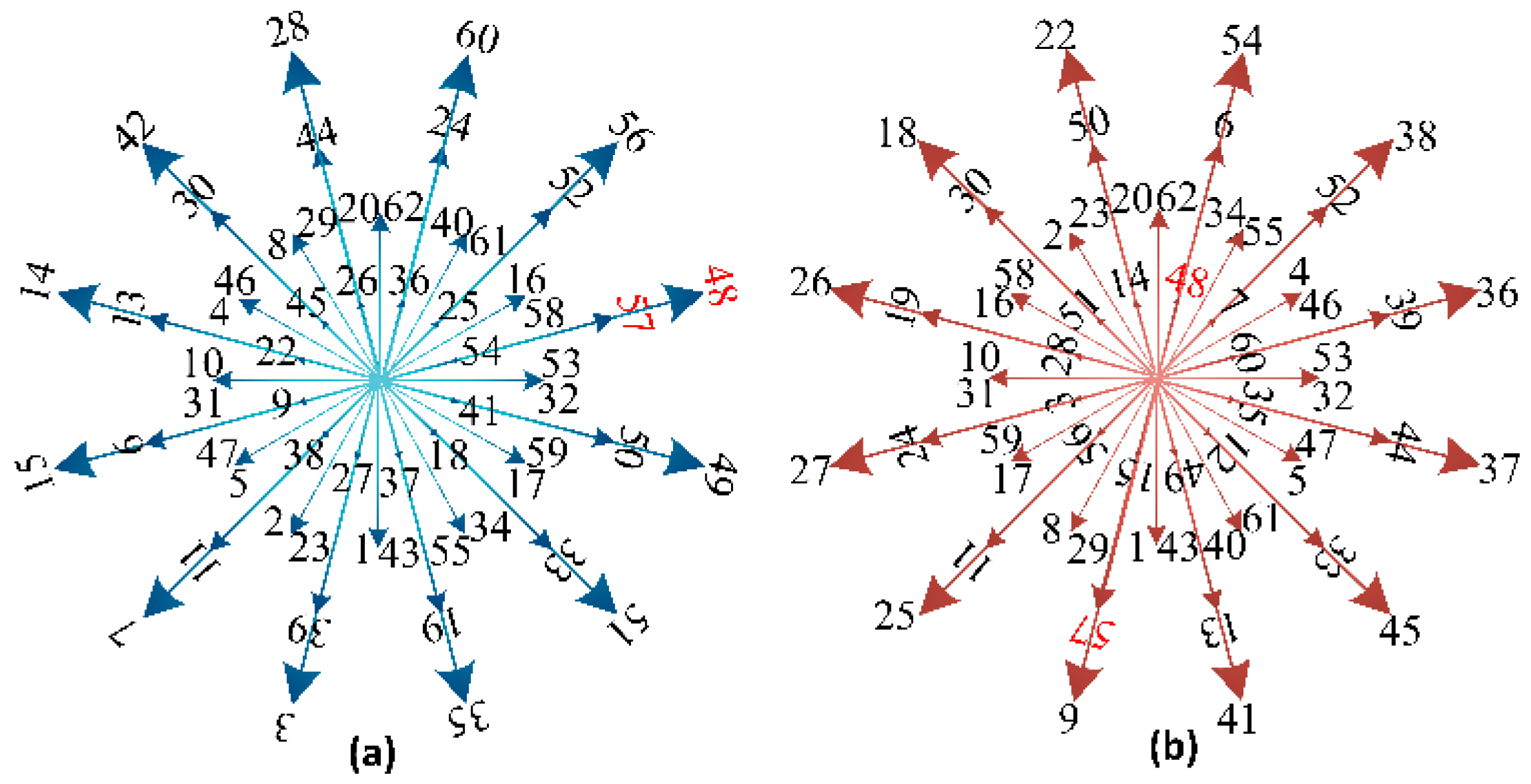
The main focus of this paper is on the parallel torque ripple and harmonic current reduction in vector control of a 6PIM. To achieve these goals, a new vector control scheme is proposed, using a combination of DTC FOC concepts to moderate steady-state torque ripples. To reduce harmonic currents, twelve virtual voltage vectors are introduced by combination of large and single medium voltage vectors (e.g., 48 and 57 in Figure 1a, respectively). The duration of each voltage vector is determined such that the average volt-seconds in the subspace becomes near to zero. Consequently, low-frequency current harmonics experience a considerable reduction, current will be much smoother, and the efficiency of the drive system will be increased.
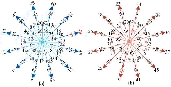
Figure 1.
6PIM model in (a) , (b) bspaces.
2. 6PIM Modelling
There are two common methods for modelling of 6PIMs: double [20] and VSD [21]. According to the VSD approach, the machine’s parameters are mapped into active and loss subspaces, which makes the control strategy more convenient and efficient. Moreover, the VSD method can easily be extended to other types of motors. In this study, the 6PIM modelling is based on the VSD strategy. According to this modelling technique, a 6PIM with near-sinusoidal distributed windings is modelled in three orthogonal subspaces, which are commonly named as the , , and subspaces. The produced voltage space vectors by switching states of a two-level six-phase voltage source inverter in the , subspaces are shown in Figure 1. Among these subspaces, only the components share useful electromechanical energy conversion, while and components do not generate any electromechanical energy in the air-gap and just produce losses. The fundamental components and also harmonics of the order are mapped into the subspace. The losses of 6PIM are mapped into the and subspaces which include harmonics by the order of and respectively. By the assumption that the stator mutual leakage inductance is ignored, the components of and subspaces have the same form [21]. Since the active and loss components are investigated separately, it is clear that the control of 6PIM will be more efficient by using VSD. Additionally, isolation of the neutral points of two three-phase windings, makes the subspace losses become zero [21].
2.1. 6PIM Model in Subspace
As already mentioned, only the subspace components contribute to the electrical energy conversion. Using the VSD strategy, the normal six-dimensional electrical components of the 6PIM are mapped into the , , and subspaces by an appropriate matrix named , which is presented in Appendix A. The voltage equations in the stationary reference frame are as follows:
where, , , , , , is the stator resistance, is the rotor resistance, is the angular speed, and is the derivative operator. The stator flux linkage () and rotor flux linkage () can be expressed as:
where, , , and M are the stator, rotor and magnetizing inductances, respectively.
2.2. 6PIM Model in Subspace
The 6PIM model in the subspace behaves as a passive resistor–inductor () circuit as:
where, is the stator leakage inductance. In this paper, 6PIM is applied with two isolated neutral points, with which this structure prevents the zero sequence currents. Hence, the components can be neglected.
3. Conventional DTC of 6PIM
In a six-phase voltage source inverter (VSI), there are switching states. Each state produces a voltage space vector (defined as ) in the or subspaces, shown in Figure 1. As can be seen, there are large (e.g., ), single medium (e.g., ), 24 double medium (e.g., ), small (e.g., ), and null voltage vectors. The block diagram of conventional DTC is shown in Figure 2.
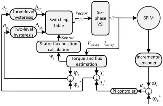
Figure 2.
Conventional DTC block diagram.
The stator flux in this approach is obtained as:
The electromagnetic torque can be calculated using the stator flux and current as:
where, is the number of pole pairs. The reference values of the stator flux and electromagnetic torque are compared with the estimated ones, and the errors are applied to the hysteresis controller. The outputs of the hysteresis regulators denote the signs of torque and flux change. In order to minimize the errors, the optimum vector is selected through ST, which is tabulated in Table 1.

Table 1.
ST of conventional DTC.
In this table, is the number of the sector. is the applied voltage vector to the inverter, which is defined as binary numbers in switching states of VSI as in Table 2.
Table 2.
Selected vectors in ST of conventional DTC.
In the conventional DTC, only the large voltage vectors in the subspace are applied to the 6PIM to maximize the utilization of the dc-link. From Equation (4), it can be seen that the stator flux variations and the applied voltage vectors have the same direction. Hence, the changes in the stator flux depend on the applied voltage vectors. Compared to the stator time constant, the rotor time constant is very large. Therefore, the rotor flux linkage changes are negligible and it can be assumed constant during short transients [22]. By the application of the active voltage vectors, stator flux linkage vector will be moved away from rotor flux linkage vector and the angle between them will be greater. This leads to changes in torque according to Equation (5).
4. Harmonic Currents Reduction by Duty Cycle Control Strategy
From Figure 1, it can be seen that each voltage vector in the subspace has a corresponding vector in the subspace with different position and magnitude. It is recommended to make the average volt-second outcome in the subspace near to zero. Accordingly, two voltage vectors have been applied to the inverter in each sampling period. Active voltage vectors should be in a same direction (in order to have high effect on torque) and their correspondents in subspace should be in an opposite direction (in order to have less losses). Therefore, the selected vectors will produce high outcome in subspace and low outcome in the subspace.
The applied voltage vectors in the subspace are expressed as:
where, and are single-medium and large voltage vectors in the subspace. A suitable duty ratio is calculated as:
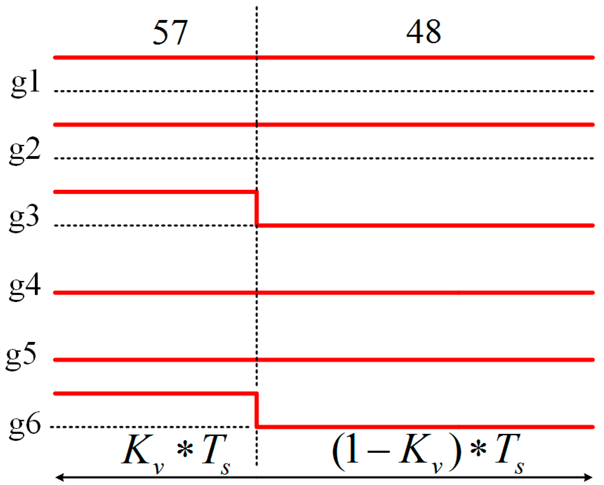
where, , and are the duration of the large and single-medium voltage vectors application in the subspace, and is the sampling period. In this way, the losses in the subspace are reduced strikingly, while the reduction in the electromagnetic components is subtle. For instance, vectors number and have the same direction in the subspace and the opposite direction in the subspace. These voltage vectors are applied to the motor as illustrated in Figure 3, where is the number of legs in six-phase VSI, and is the duty ratio defined as:
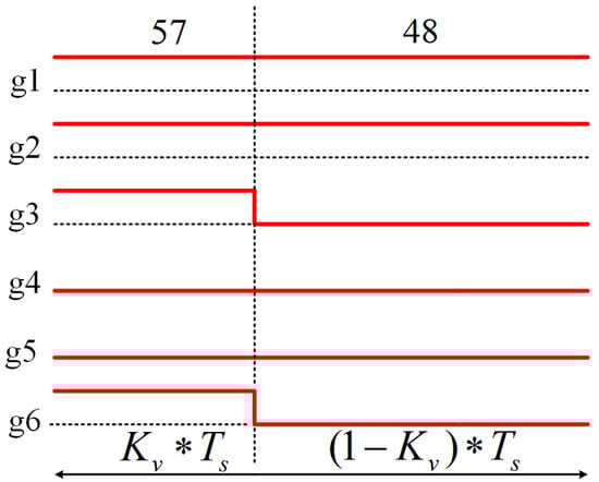
Figure 3.
Switching pattern.
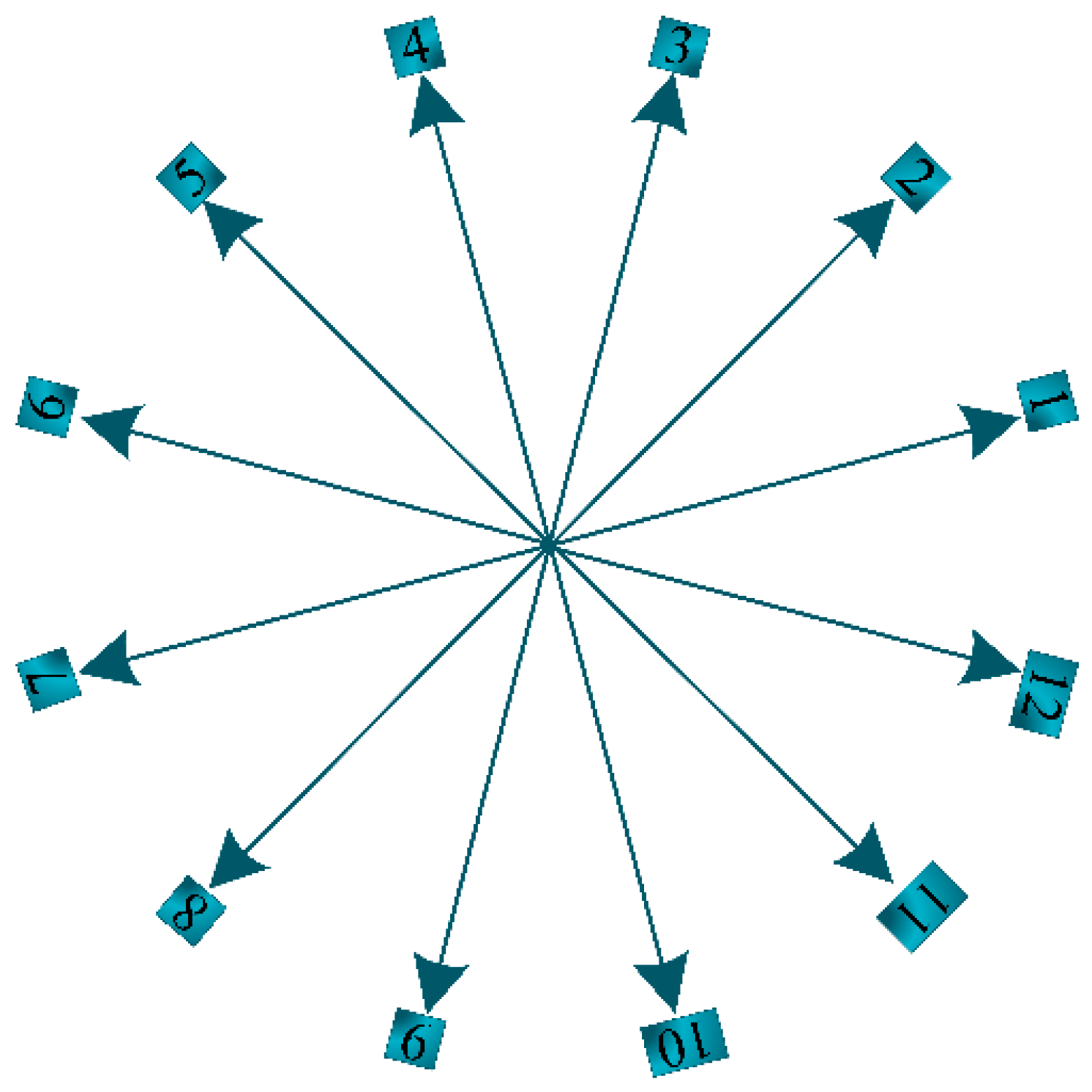
If the upper switch is on and the lower switch is off. On the contrary, when , the lower switch becomes on and the upper switch turns off. The compound of these vectors in each sampling period is named virtual vector, shown in Figure 4.
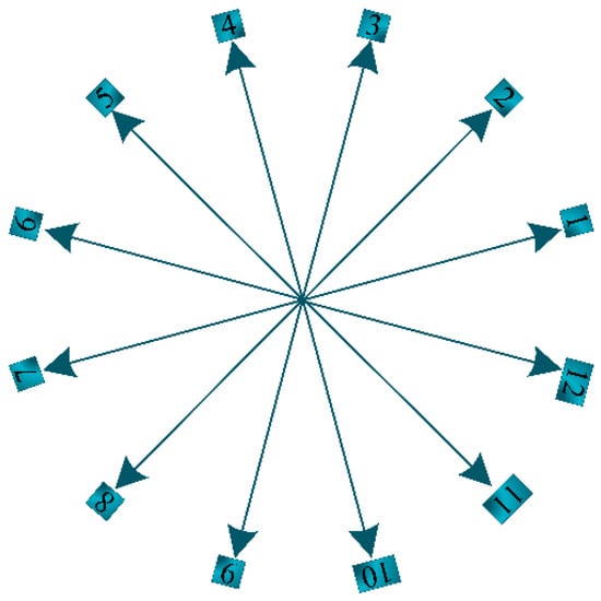
Figure 4.
Virtual vectors in α-β subspace.
Figure 3 shows that in two legs (among the six legs) of the inverter, the switches’ status has been changed. Therefore, by this method has more switching frequency against DTC. This increase in switching frequency is less than twice. The vectors in the subspace are replaced by virtual vectors in ST shown in Table 2.
5. Proposed Control Algorithm for the 6PIM Drive
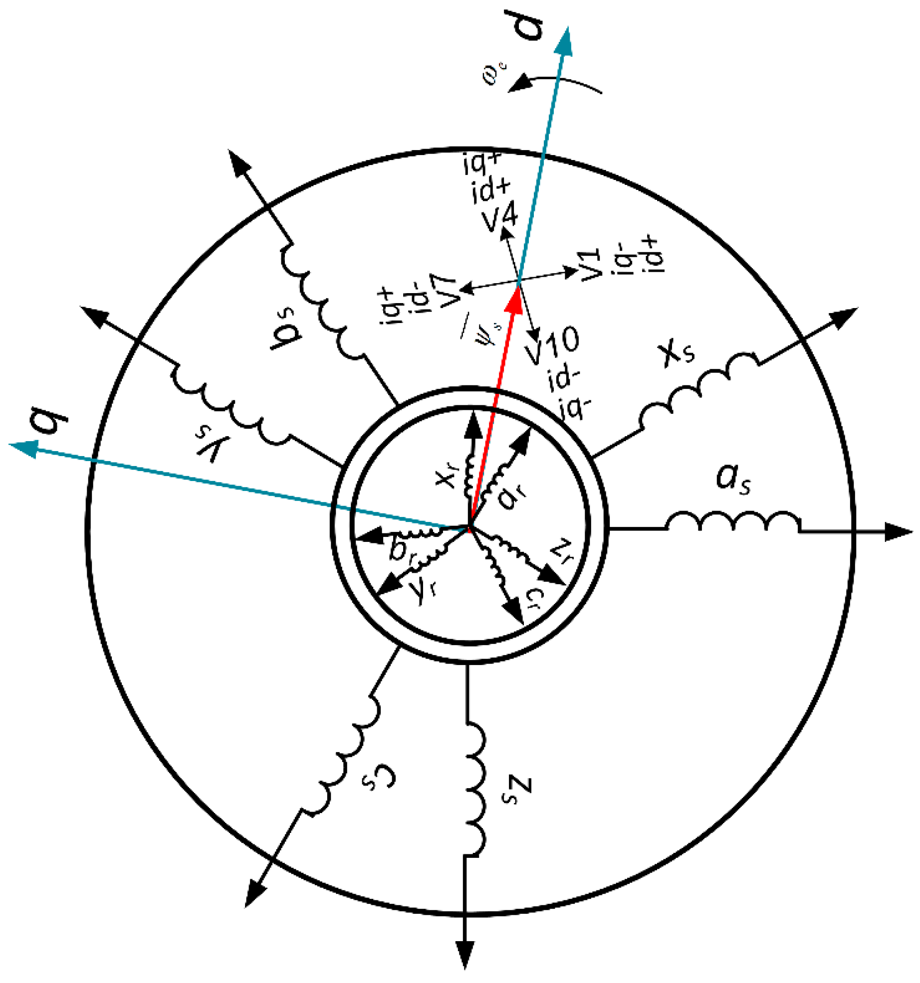
Using FOC framework [23], 6PIM’s mathematical equations are transformed to the synchronous reference frame (), which creates possibility of decoupled control of the torque and flux as a permanent-magnet separated-excitation motor. In this reference frame, the stator flux vector is located on d-axis which is shown in Figure 5.
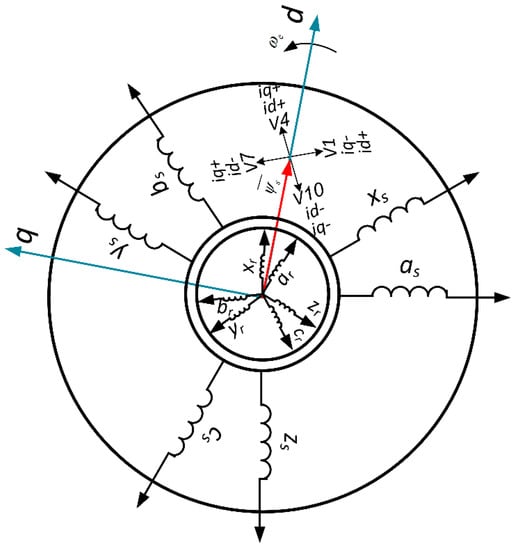
Figure 5.
6PIM structure and stator flux vector in 3rd sector and applied inverter voltage vectors.
Orthogonal currents of the 6PIM are mapped into the synchronous reference frame using Park transformation based on the flux vector position, which is achieved by field orientation process. For the 6PIM control, is a torque -and is a flux- producing components. Hence, the equations of the torque and flux are related to stator currents in the frame as follows:
In order to decrease the torque ripples in the 6PIM, a new approach is employed by modifying the ST’s inputs. Since the inputs of the ST in the classical ST-DTC are the errors between command and actual values of the electromagnetic torque and the stator flux, it seems effective to use the errors between the set and actual values of the , , instead. In order to redesign the ST-DTC method to use these inputs, the inputs of ST in the conventional DTC are used as inputs for PI regulators. The outputs of PI regulators are the command values of the currents in the axis. Replacing , by , in ST-DTC, respectively, the proposed method provides better inputs to the same ST presented in Table 1 which leads to a better performance in 6PIM. Table 3 shows that through defining virtual vectors, the ST is the same with conventional DTC with different inputs.
Table 3.
The switching table of the proposed scheme.
and imply that changing the signs of the and is required. If needs to be increased, then . If there is no requirement, then . Also, denotes the decrease of . All the states are defined as the same for the notation of . These digital output signals of the hysteresis controllers are described as:
Similarly, for the changes required for the d-axis of the stator current, is described as:
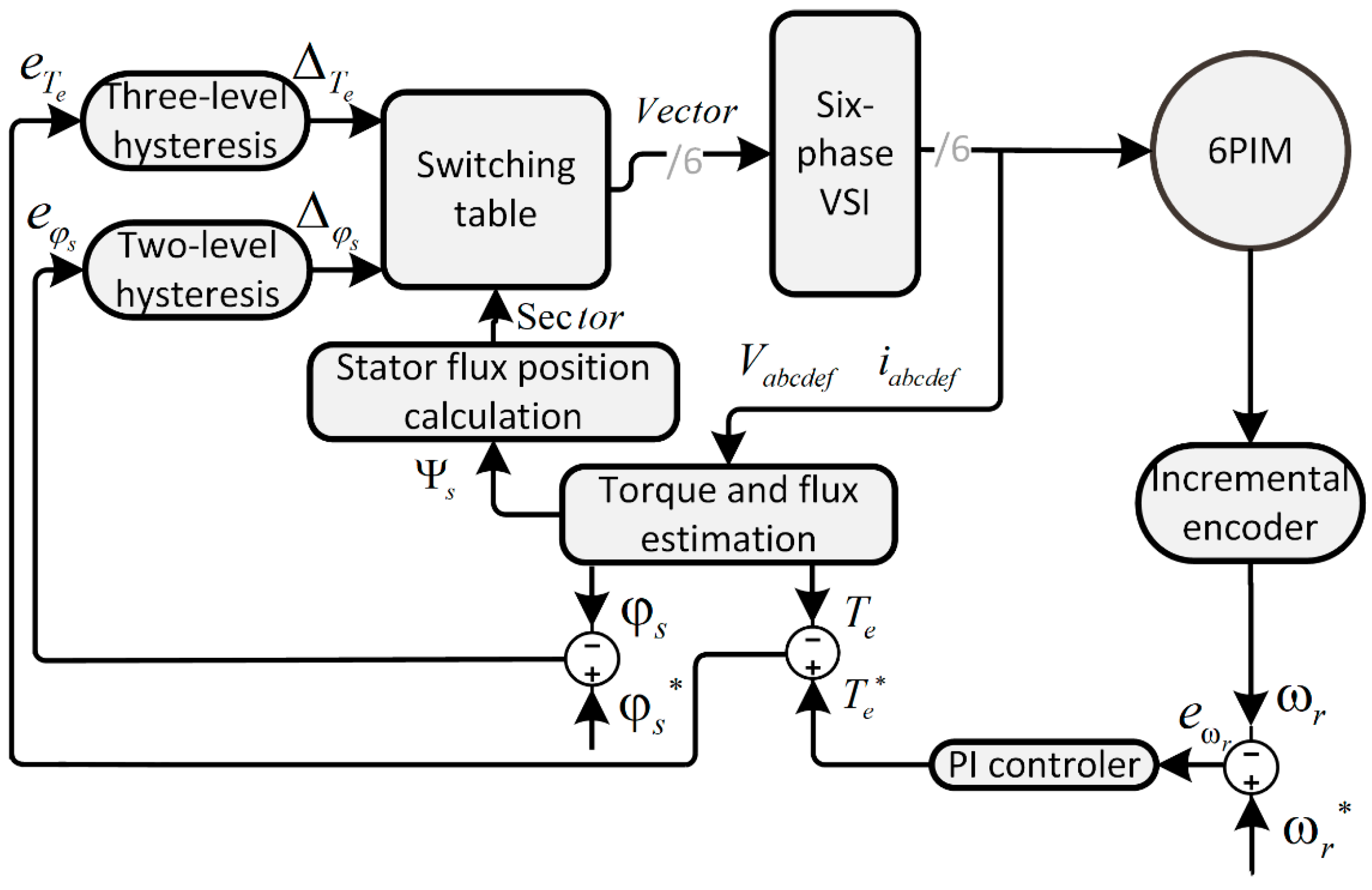
The block diagram of the proposed control strategy is shown in Figure 6. To concurrently achieve low Total Harmonics Distortion )THD( of the motor currents and low torque ripples, the proposed vector control scheme is synthesized with the duty cycle control strategy. The ST applies two voltage vectors in each sampling period in order to eliminate subspace components. In comparison with the conventional DTC, the switching frequency of the proposed scheme is increased (less than twice according to Figure 3.) because two voltage vectors are applied in each sampling period. In contrary, both harmonic currents and torque ripples are reduced. Moreover, the proposed scheme has fast dynamic response, similar to the conventional DTC, and does not need any PWM modulator that creates complexity and time delay.
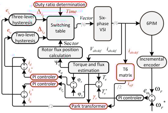
Figure 6.
Block diagram of the proposed control scheme for 6PIM.
6. Simulation Results
The proposed and duty cycle control methods are simulated in MATLAB/Simulink. The sampling period of both methods are set to All the parameters are assumed to be constant, although each of them can be changed under the thermal effect, which is not within the scope of this essay. The simulations are carried out based on real specifications for 6PIM. The 6PIM parameters are specified in Table 4.
Table 4.
6PIM parameters.
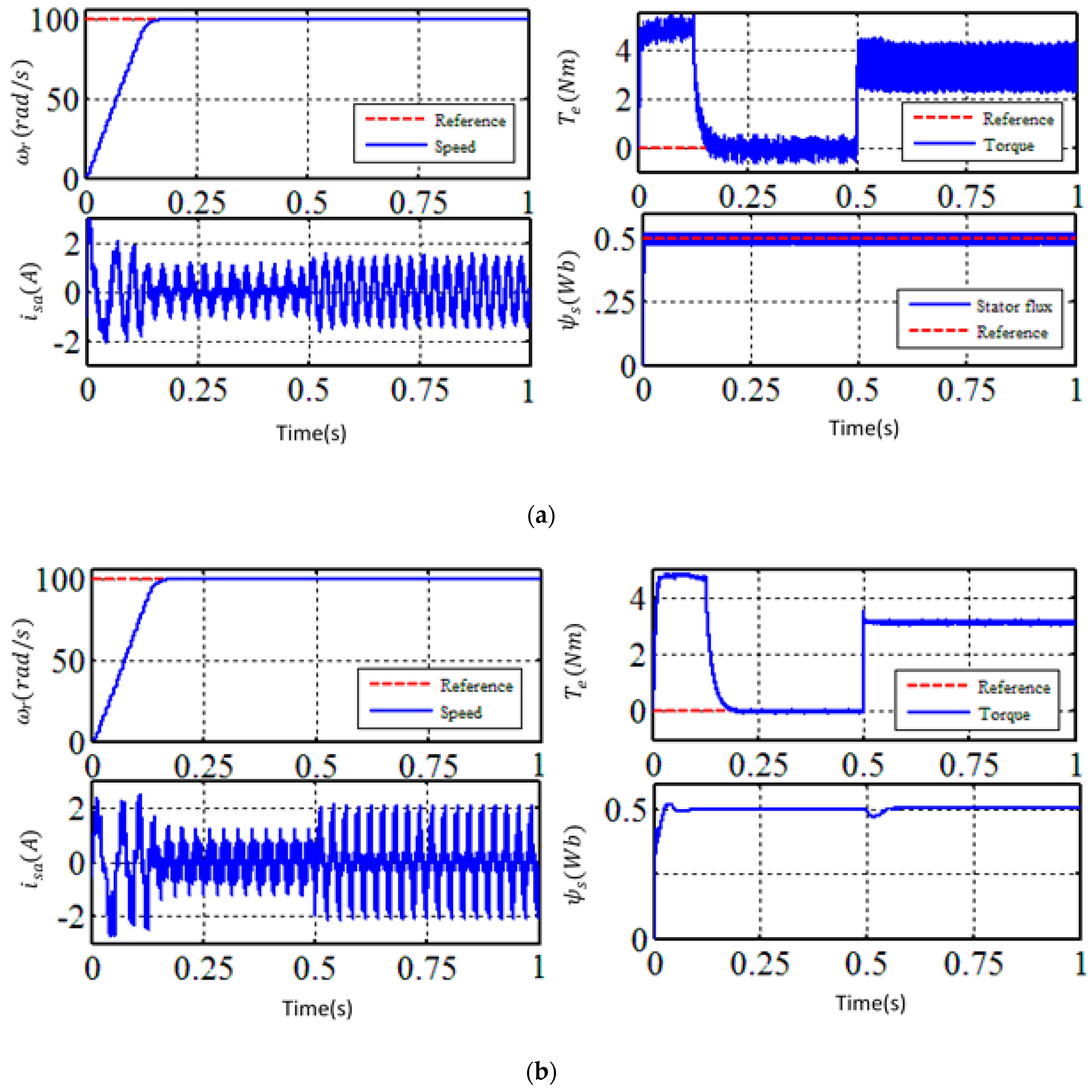
The simulation results for the duty cycle and the proposed DTC strategies under load change from to about at , speed command of , and flux command of are shown in Figure 7 and Figure 8, a speed torque and stator flux reference signals are shown with red dashed lines.
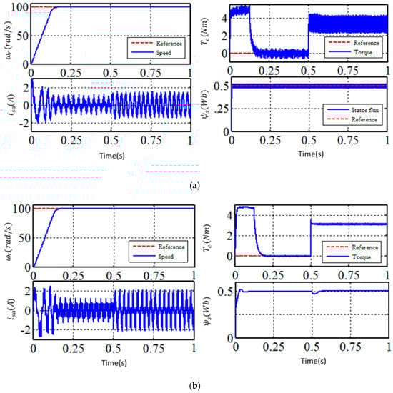
Figure 7.
Load change condition of the 6PIM controlled by the duty cycle control strategy (a) and proposed method (b).
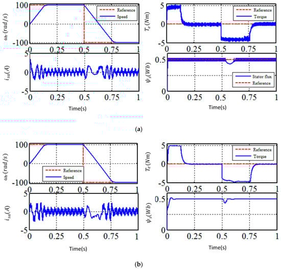
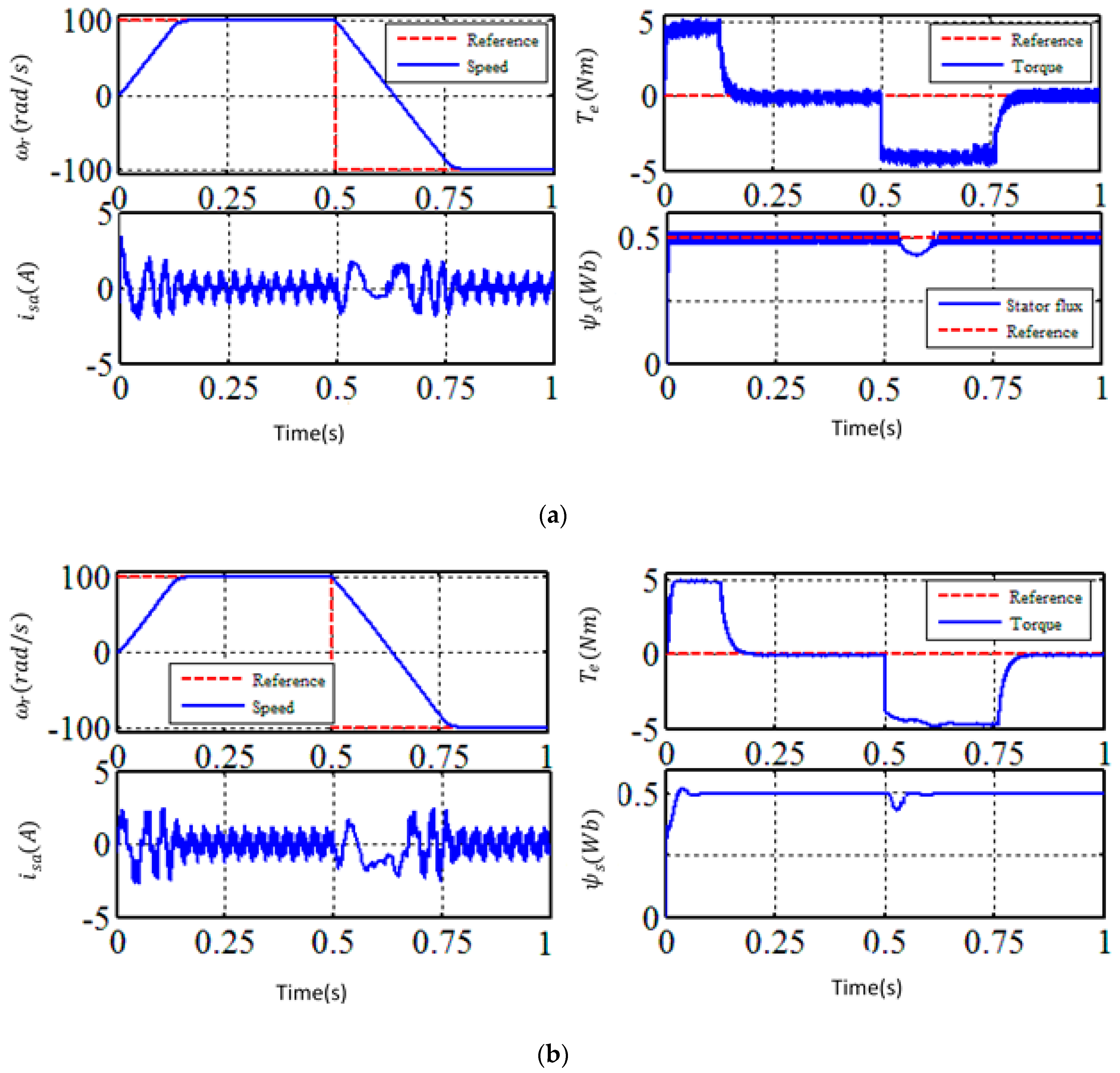
Figure 8.
Speed direction change condition of the 6PIM controlled by the duty cycle control strategy (a) and proposed method (b).
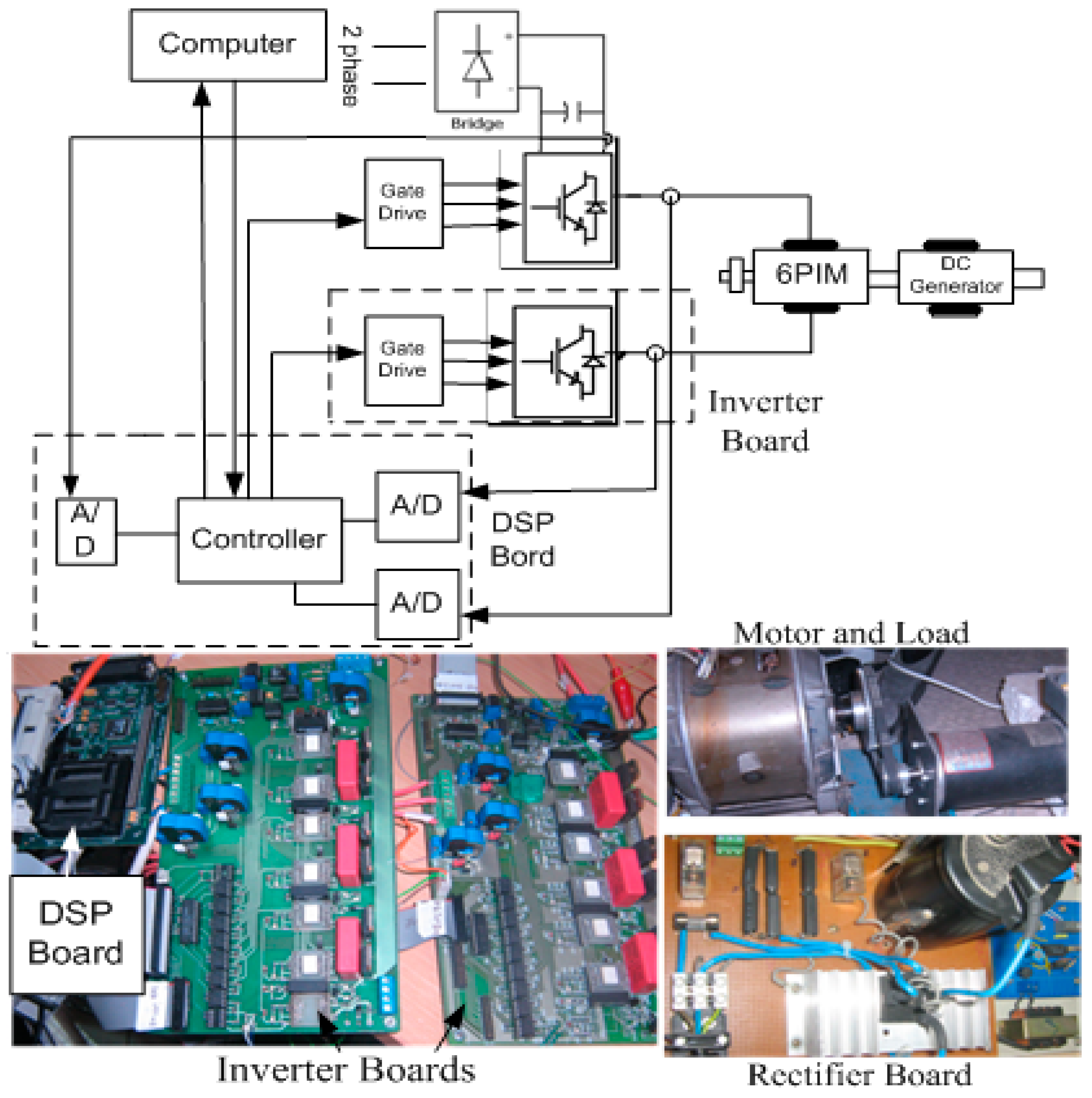
7. Experimental Setup
In addition to the simulations, the performance of the proposed method is validated experimentally. Figure 9 shows the experimental setup, which contains the 6PIM and its coupled load, the main processor, two three-phase VSIs, current and voltage transducers, shaft encoder, and single-phase bridge rectifier.

Figure 9.
Experimental setup.
The applied processor used in the driver is an eZDSP F28335 based on the floating point TMS320F28335 chip. The motor speed is measured by an Autonics incremental shaft encoder (Autonics, Busan, South Korea) mechanically coupled to the 6PIM with resolution of . LEM LTS6np current transducers are implemented to measure all the phases’ currents in order to be used in the estimation and the control processes. The DC-link voltage is also measured using voltage transducer. A DC generator is applied as load machine and a PCI-1716 data acquisition card (DAQ, Advantech, Milpitas, CA, USA) as an A/D converter. A 700-W, 24-stator slots three-phase squirrel-cage induction motor, which has been rewound to construct a 4-pole asymmetrical 6PIM is also tested for the proposed method performance. The MATLAB/Embedded Coder is used to generate usable code for the code composer studio development environment. The digital motor control and IQmath libraries along with IQ17 data type are employed. The sampling period is set to with a dead-time of .
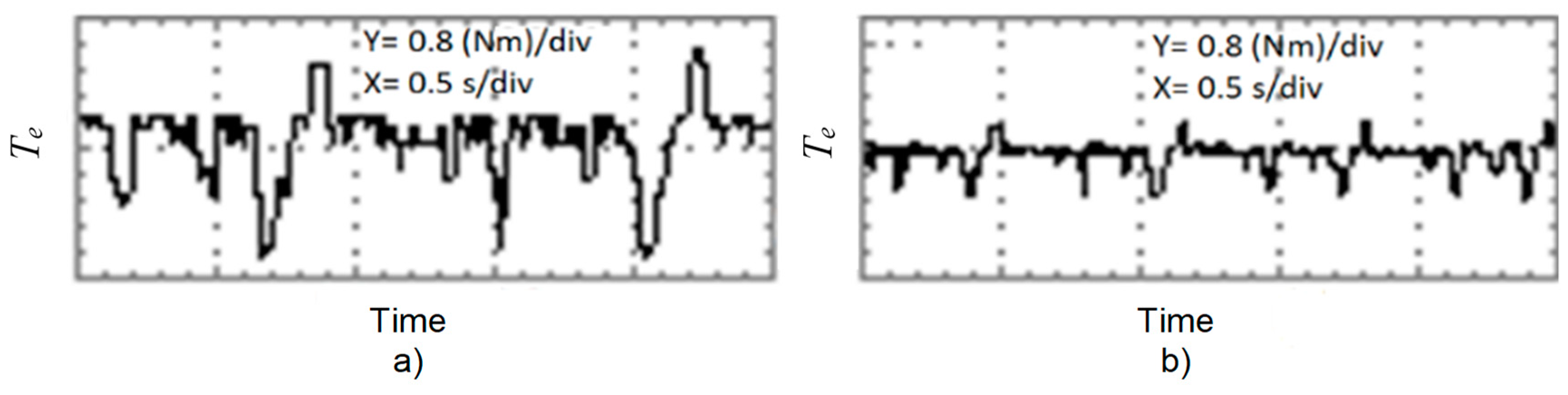
To demonstrate the torque ripples reduction precisely, the torque figures are shown within a short time frame in Figure 10.
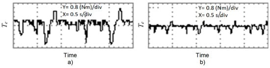
Figure 10.
The torque response of the 6PIM in steady state with 4 Nm load, derived by (a) duty cycle control strategy; (b) proposed method.
The experimental results of the duty cycle control strategy and the proposed method under the load changing from to about are shown in Figure 11. In this test, the speed and flux commands are and , respectively. The provided tests illustrate the alleviation of torque ripples in the proposed method compared with the duty cycle control strategy.
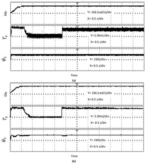
Figure 11.
Load injection experiment of 6PIM, controlled by duty cycle control strategy (a) and proposed method (b).
In Table 5, the torque ripples in the no load condition are investigated to show the differences between the proposed method and the conventional DTC and the duty cycle control-based DTC strategies. It is clear that the torque ripples for the 6PIM is effectively decreased for the proposed method in comparison with other two methods. Furthermore, as it is seen from current THD in Figure 12, the low order harmonics of the stator currents, especially the fifth and seventh harmonics, are considerably reduced for the proposed control method.
Table 5.
Torque ripples in three different conditions of 6PIM driving by three different methods.
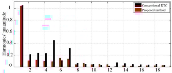
Figure 12.
Current THD of the conventional DTC and proposed method.
8. Conclusions
In this paper the performance of the 6PIM was improved by a new vector control strategy. Using a new set of inputs for the ST in DTC method and applying the duty cycle control strategy leads to decrease in both torque ripples and harmonic currents. From a complexity viewpoint, the proposed technique falls between the DTC and FOC. This method is more simple compared with FOC strategy due to the absence of PWM algorithm, and has a fast dynamic similar to DTC strategy. The main limitation of the proposed technique is variable switching frequency compared with FOC. The effectiveness of the proposed control strategy was confirmed using both simulation and experimental tests.
Author Contributions
Methodology, validation and formal analysis, H.H.; writing—original draft H.H., A.T., M.H.H.; writing—review & editing, A.R., T.V. and A.K.; supervision, A.B.
Funding
This work was supported by the Estonian Research Council under Grants PUT1260.
Conflicts of Interest
The authors declare no conflict of interest.
Appendix A
References
- Levi, E. Multiphase electric machines for variable-speed applications. IEEE Trans. Ind. Electron. 2008, 55, 1893–1909. [Google Scholar] [CrossRef]
- Holakooie, M.H.; Ojaghi, M.; Taheri, A. Direct Torque Control of Six-Phase Induction Motor with a Novel MRAS-Based Stator Resistance Estimator. IEEE Trans. Ind. Electron. 2018, 65, 7685–7696. [Google Scholar] [CrossRef]
- Che, H.S.; Duran, M.J.; Levi, E.; Jones, M.; Hew, W.P.; Rahim, N.A. Postfault operation of an asymmetrical six-phase induction machine with single and two isolated neutral points. IEEE Trans. Power Electron. 2014, 29, 5406–5416. [Google Scholar] [CrossRef]
- Jahns, T.M. Improved reliability in solid-state drives for large asynchronous ac machines by means of multiple independent phase-drive units. IEEE Trans. Ind. Appl. 1980, IA-16, 321–331. [Google Scholar] [CrossRef]
- Fnaiech, M.A.; Betin, F.; Capolino, G.A.; Fnaiech, F. Fuzzy logic and sliding-mode controls applied to six-phase induction machine with open phases. IEEE Trans. Ind. Electron. 2010, 57, 354–364. [Google Scholar] [CrossRef]
- Parsa, L.; Toliyat, H.A.; Goodarzi, A. Five-phase interior permanent-magnet motors with low torque pulsation. IEEE Trans. Ind. Appl. 2007, 43, 40–46. [Google Scholar] [CrossRef]
- Marouani, K.; Baghli, L.; Hadiouche, D.; Kheloui, A.; Rezzoug, A. A new PWM strategy based on a 24-sector vector space decomposition for a six-phase VSI-Fed dual stator induction motor. IEEE Trans. Ind. Electron. 2008, 55, 1910–1920. [Google Scholar] [CrossRef]
- Pandit, J.K.; Aware, M.V.; Nemade, R.V.; Levi, E. Direct Torque Control Scheme for a Six-Phase Induction Motor with Reduced Torque Ripple. IEEE Trans. Power Electron. 2017, 32, 7118–7129. [Google Scholar] [CrossRef]
- Zheng, L.; Fletcher, J.E.; Williams, B.W.; He, X. A novel direct torque control scheme for a sensorless five-phase induction motor drive. IEEE Trans. Ind. Electron. 2011, 58, 503–513. [Google Scholar] [CrossRef]
- Lokriti, A.; Salhi, I.; Doubabi, S. IM Direct Torque Control with no flux distortion and no static torque error. ISA Trans. 2015, 59, 256–267. [Google Scholar] [CrossRef]
- Ambrozic, A.; Buja, G.S.; Menis, R. Band-Constrained Technique for Direct Torque Control of Induction Motor. IEEE Trans. Ind. Electron. 2004, 51, 776–784. [Google Scholar] [CrossRef]
- Ren, Y.; Zhu, Z.Q. Enhancement of steady-state performance in direct-torque-controlled dual three-phase permanent-magnet synchronous machine drives with modified switching table. IEEE Trans. Ind. Electron. 2015, 62, 3338–3350. [Google Scholar] [CrossRef]
- Taheri, A.; Rahmati, A.; Kaboli, S. Comparison of efficiency for different switching tables in six-phase induction motor DTC drive. J. Power Electron. 2012, 12, 128–135. [Google Scholar] [CrossRef]
- Singh, B.; Jain, S.; Dwivedi, S. Torque ripple reduction technique with improved flux response for a direct torque control induction motor drive. IET Power Electron. 2013, 6, 326–342. [Google Scholar] [CrossRef]
- Lai, Y.S.; Chen, J.H. A new approach to direct torque control of induction motor drives for constant inverter switching frequency and torque ripple reduction. IEEE Trans. Energy Convers. 2001, 16, 220–227. [Google Scholar]
- Shyu, K.K.; Lin, J.K.; Pham, V.T.; Yang, M.J.; Wang, T.W. Global minimum torque ripple design for direct torque control of induction motor drives. IEEE Trans. Ind. Electron. 2010, 57, 3148–3156. [Google Scholar] [CrossRef]
- Abad, G.; Rodriguez, M.A.; Poza, J. Two-Level VSC Based Predictive Direct Torque Control of the Doubly Fed Induction Machine with Reduced Torque and Flux Ripples at Low Constant Switching Frequency. IEEE Trans. Power Electron. 2008, 23, 1050–1061. [Google Scholar] [CrossRef]
- Wang, T.; Fang, F.; Wu, X.; Jiang, X. Novel filter for stator harmonic currents reduction in six-step converter fed multiphase induction motor drives. IEEE Trans. Power Electron. 2013, 28, 498–506. [Google Scholar] [CrossRef]
- Autsou, S.; Saroka, V.; Karpovich, D.; Rassolkin, A.; Gevorkov, L.; Vaimann, T.; Kallaste, A.; Belahcen, A. Comparative study of field-oriented control model in application for induction and synchronous reluctance motors for life-cycle analysis. In Proceedings of the 2018 25th International Workshop on Electric Drives: Optimization in Control of Electric Drives (IWED), Moscow, Russia, 31 January–2 February 2018. [Google Scholar]
- Nelson, R.H.; Krause, P.C. Induction machine analysis for arbitrary displacement between multiple winding sets. IEEE Trans. Power Appar. Syst. 1974, PAS-93, 841–848. [Google Scholar] [CrossRef]
- Zhao, Y.; Lipo, T.A. Space Vector PWM Control of Dual Three-phase Induction Machine Using Vector Space Decomposition. IEEE Trans. Ind. Appl. 1995, 31, 1100–1109. [Google Scholar] [CrossRef]
- Binder, A.; Muetze, A. Scaling effects of inverter-induced bearing currents in AC machines. IEEE Trans. Ind. Appl. 2008, 44, 769–776. [Google Scholar] [CrossRef]
- Holakooie, M.H.; Taheri, A.; Sharifian, M.B.B. MRAS based speed estimator for sensorless vector control of a linear induction motor with improved adaptation mechanisms. J. Power Electron. 2015, 15, 1274–1285. [Google Scholar] [CrossRef]


© 2019 by the authors. Licensee MDPI, Basel, Switzerland. This article is an open access article distributed under the terms and conditions of the Creative Commons Attribution (CC BY) license (http://creativecommons.org/licenses/by/4.0/).