Design and Analysis of Outer Rotor Permanent-Magnet Vernier Machines with Overhang Structure for In-Wheel Direct-Drive Application


Abstract
:1. Introduction
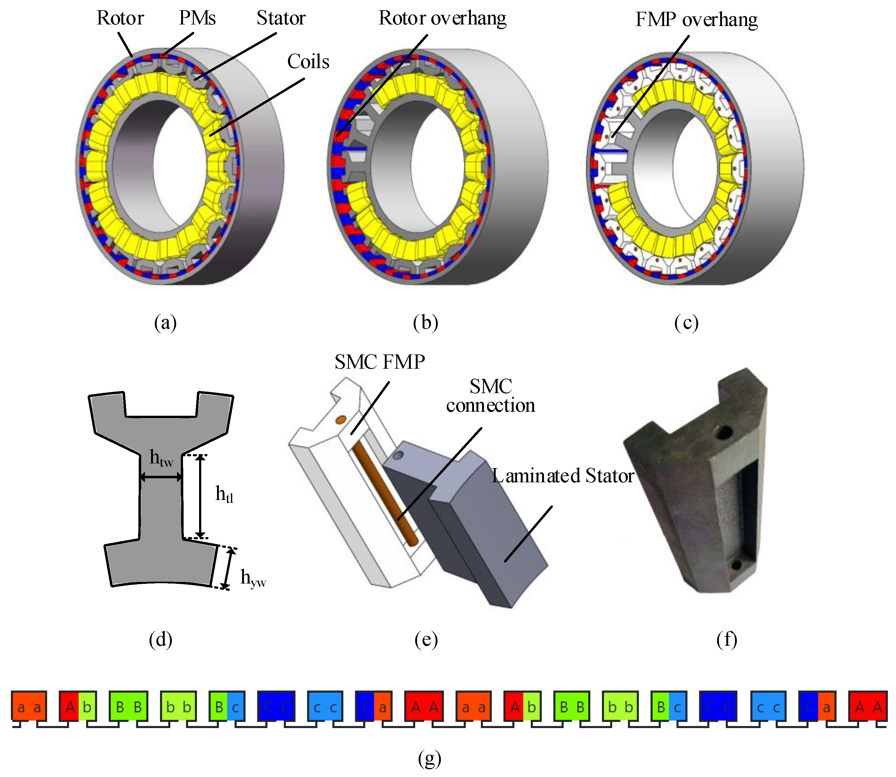
2. Operation Principle and Machine Configurations
3. FEA and Comparisons
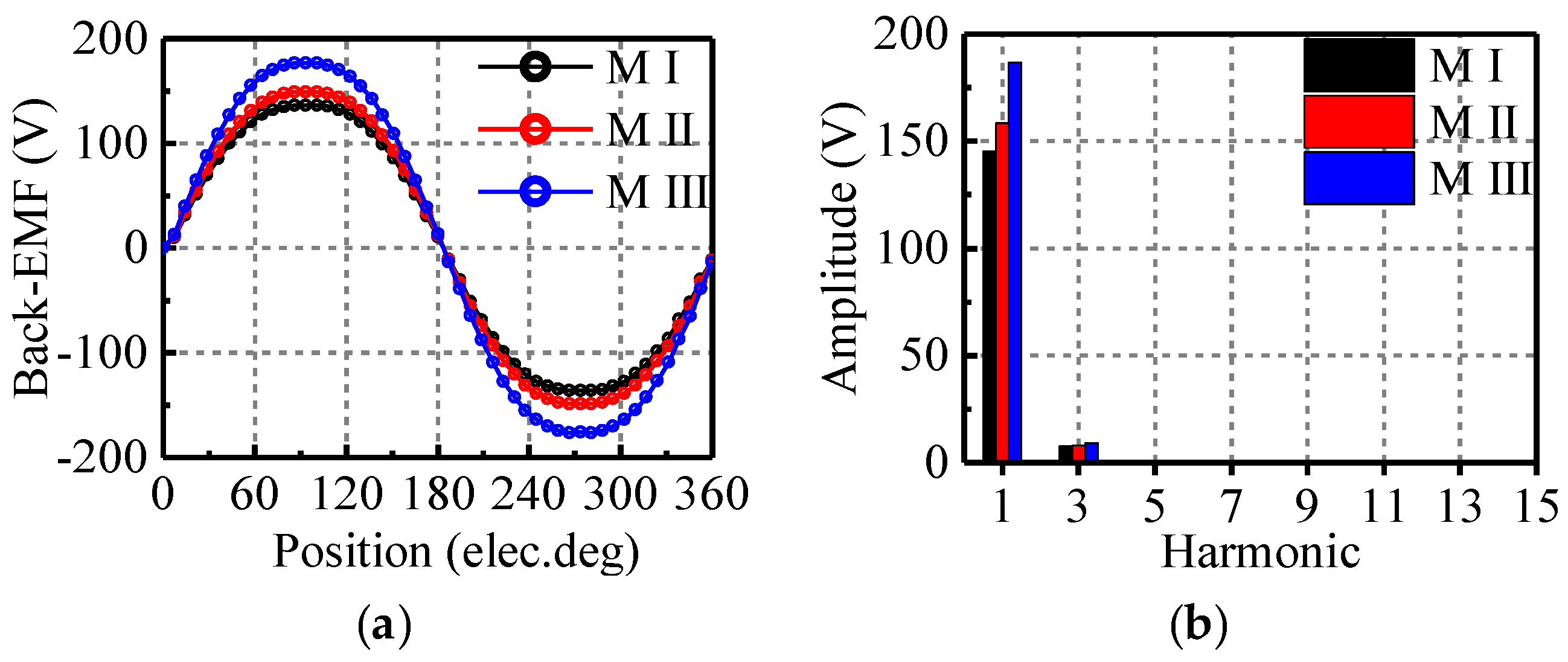
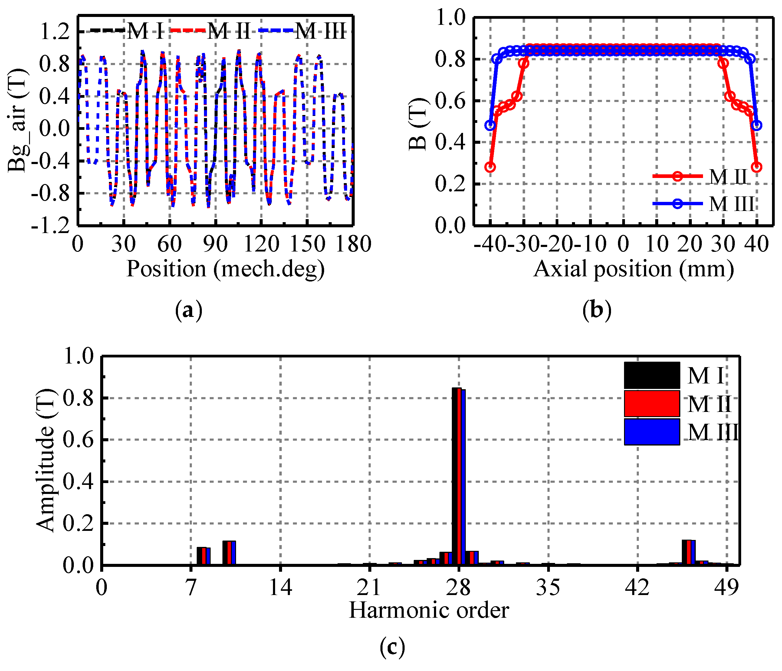
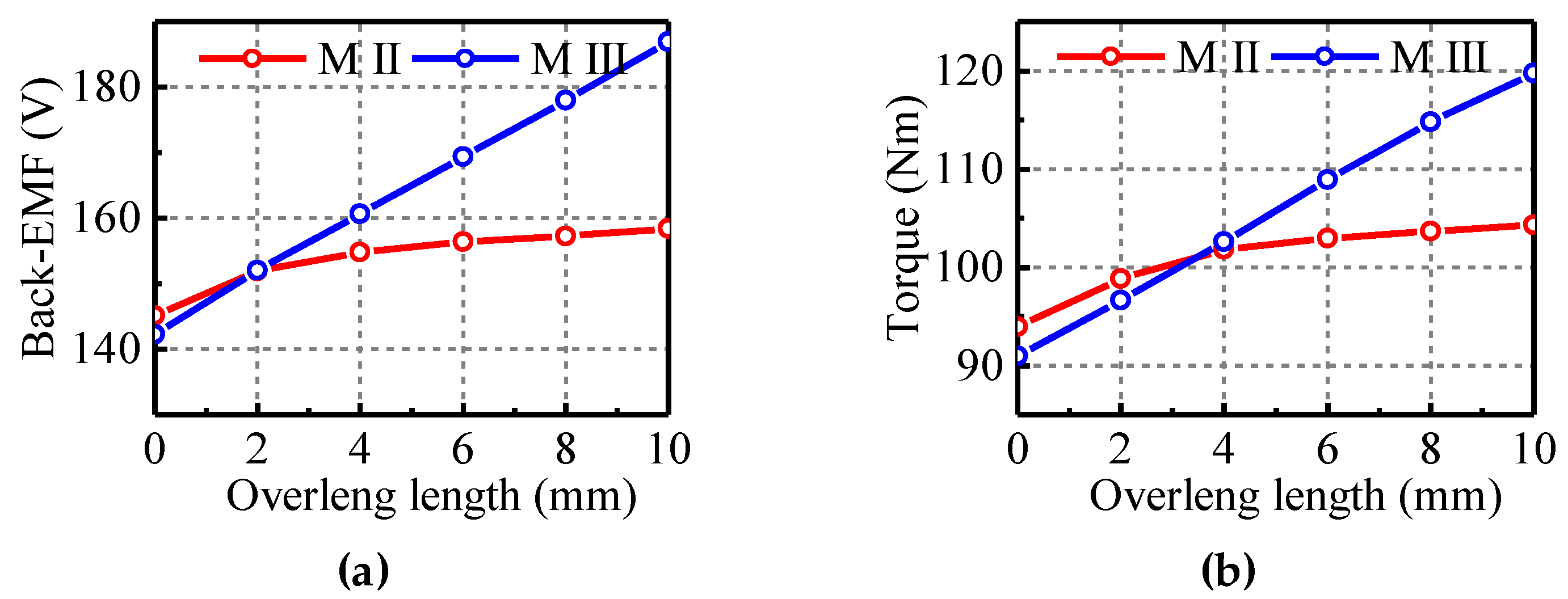
3.1. No-Load Characteristics
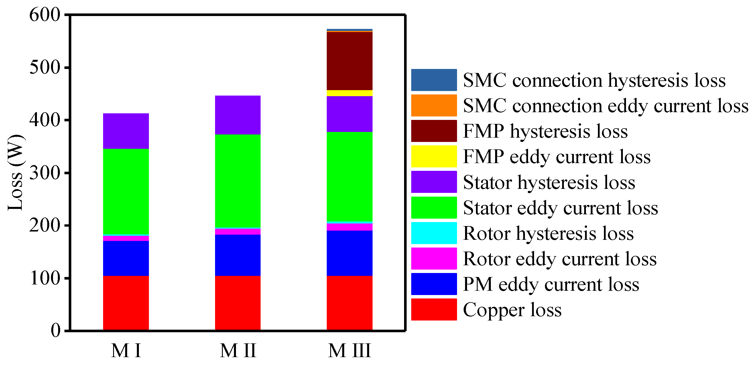
3.2. On-Load Characteristics
4. Conclusions
Author Contributions
Funding
Conflicts of Interest
References
- Lee, C.H. Vernier motor and its design. IEEE Trans. Power Appl. Syst. 1963, 82, 343–349. [Google Scholar] [CrossRef]
- Toba, A.; Lipo, T.A. Generic torque-maximizing design methodology of surface permanent-magnet vernier machine. IEEE Trans. Ind. Appl. 2000, 36, 1539–1546. [Google Scholar]
- Gu, C.; Zhao, W.; Zhang, B. Simplified Minimum Copper Loss Remedial Control of a Five-Phase Fault-Tolerant Permanent-Magnet Vernier Machine under Short-Circuit Fault. Energies 2016, 9, 860. [Google Scholar] [CrossRef]
- Kim, B.; Lipo, T.A. Operation and Design Principles of a PM Vernier Motor. IEEE Trans. Ind. Appl. 2014, 6, 3656–3663. [Google Scholar] [CrossRef]
- Kim, B.; Lipo, T.A. Analysis of a PM vernier motor with spoke structure. IEEE Trans. Ind. Appl. 2016, 52, 217–225. [Google Scholar] [CrossRef]
- Jang, D.; Chang, J. A Novel Design Method for the Geometric Shapes of Flux Modulation Poles in the Surface-Mounted Permanent Magnet Vernier Machines. Energies 2017, 10, 1551. [Google Scholar] [CrossRef]
- Zhang, Y.; Lin, H.; Fang, S.; Huang, Y.; Yang, H.; Wang, D. Air-gap flux density characteristics comparison and analysis of permanent magnet vernier machines with different rotor topologies. IEEE Trans. Appl. Supercond. 2016, 26, 1–5. [Google Scholar] [CrossRef]
- Li, D.; Qu, R.; Lipo, T.A. High-power-factor vernier permanent-magnet machines. IEEE Trans. Ind. Appl. 2014, 50, 3664–3674. [Google Scholar] [CrossRef]
- Li, X.; Chau, K.T.; Cheng, M. Comparative analysis and experimental verification of an effective permanent-magnet vernier machine. IEEE Trans. Magn. 2015, 51, 1–9. [Google Scholar]
- Liu, G.; Chen, M.; Zhao, W.; Chen, Q.; Zhao, W. Design and analysis of five-phase fault-tolerant interior permanent-magnet Vernier machine. IEEE Trans. Appl. Supercond. 2016, 26, 1–5. [Google Scholar] [CrossRef]
- Yang, H.; Lin, H.; Zhu, Z.-Q.; Fang, S.; Huang, Y. A Dual-Consequent-Pole Vernier Memory Machine. Energies 2016, 9, 134. [Google Scholar] [CrossRef]
- Oner, Y.; Zhu, Z.Q.; Wu, L.J.; Ge, X.; Zhan, H.; Chen, J.T. Analytical on-load subdomain field model of permanent-magnet vernier machines. IEEE Trans. Ind. Electron. 2016, 63, 4105–4117. [Google Scholar] [CrossRef]
- Liu, X.; Zhong, X.; Du, Y.; Chen, X.; Wang, D.; Ching, T.W. A New Magnetic Field Modulation Type of Brushless Double-Fed Machine. IEEE Trans. Appl. Supercond. 2018, 28, 1–5. [Google Scholar] [CrossRef]
- Xu, L.; Liu, G.; Zhao, W.; Yang, X.; Cheng, R. Hybrid stator design of fault-tolerant permanent-magnet vernier machines for direct-drive applications. IEEE Trans. Ind. Electron. 2017, 64, 179–190. [Google Scholar] [CrossRef]
- Seo, J.M.; Jung, I.S.; Jung, H.K.; Ro, J.S. Analysis of overhang effect for a surface-mounted permanent magnet machine using a lumped magnetic circuit model. IEEE Trans. Magn. 2014, 50, 1–7. [Google Scholar]
- Yeo, H.K.; Park, H.J.; Seo, J.M.; Jung, S.Y.; Ro, J.S.; Jung, H.K. Electromagnetic and thermal analysis of a surface-mounted permanent-magnet motor with overhang structure. IEEE Trans. Magn. 2017, 53, 1–4. [Google Scholar] [CrossRef]
- Min, S.G.; Bobba, D.; Sarlioglu, B. Analysis of overhang effects using conductor separation method in coreless-type PM linear machines. IEEE Trans. Magn. 2018, 54, 1–4. [Google Scholar] [CrossRef]
- Ishikawa, T.; Sato, Y.; Kurita, N. Performance of novel permanent magnet synchronous machines made of soft magnetic composite core. IEEE Trans. Magn. 2014, 50, 1–4. [Google Scholar] [CrossRef]
- Wn, F.; El-Refaie, A.M. Permanent magnet vernier machine: A review. IET Electr. Power Appl. 2019, 13, 127–137. [Google Scholar]
- Okada, K.; Niguchi, N.; Hirata, K. Analysis of a Vernier Motor with Concentrated Windings. IEEE Trans. Magn. 2013, 49, 2241–2244. [Google Scholar] [CrossRef]


| Parameters | M I | M II | M III |
|---|---|---|---|
| Number of stator slots | 18 | ||
| Number of FMPs | 36 | ||
| Number of rotor pole pairs | 28 | ||
| Number of winding pole pairs | 8 | ||
| Gear ratio | −28:8 | ||
| Rotor outer diameter (mm) | 250 | ||
| Stator outer diameter (mm) | 228 | ||
| Stator inner diameter (mm) | 140 | 134 | 128 |
| Air-gap length (mm) | 1 | ||
| PM width (mm) | 12 | ||
| PM thick (mm) | 4 | ||
| Rotor axial length (mm) | 60 | 80 | 80 |
| Stator axial length (mm) | 60 | 60 | 60 |
| FMP axial length (mm) | 60 | 60 | 80 |
| Stator tooth width htw (mm) | 10.0 | 11.5 | 13.0 |
| Stator tooth length htl (mm) | 20.3 | 22.5 | 24.4 |
| Stator yoke width hyw (mm) | 8.0 | 9.0 | 10.0 |
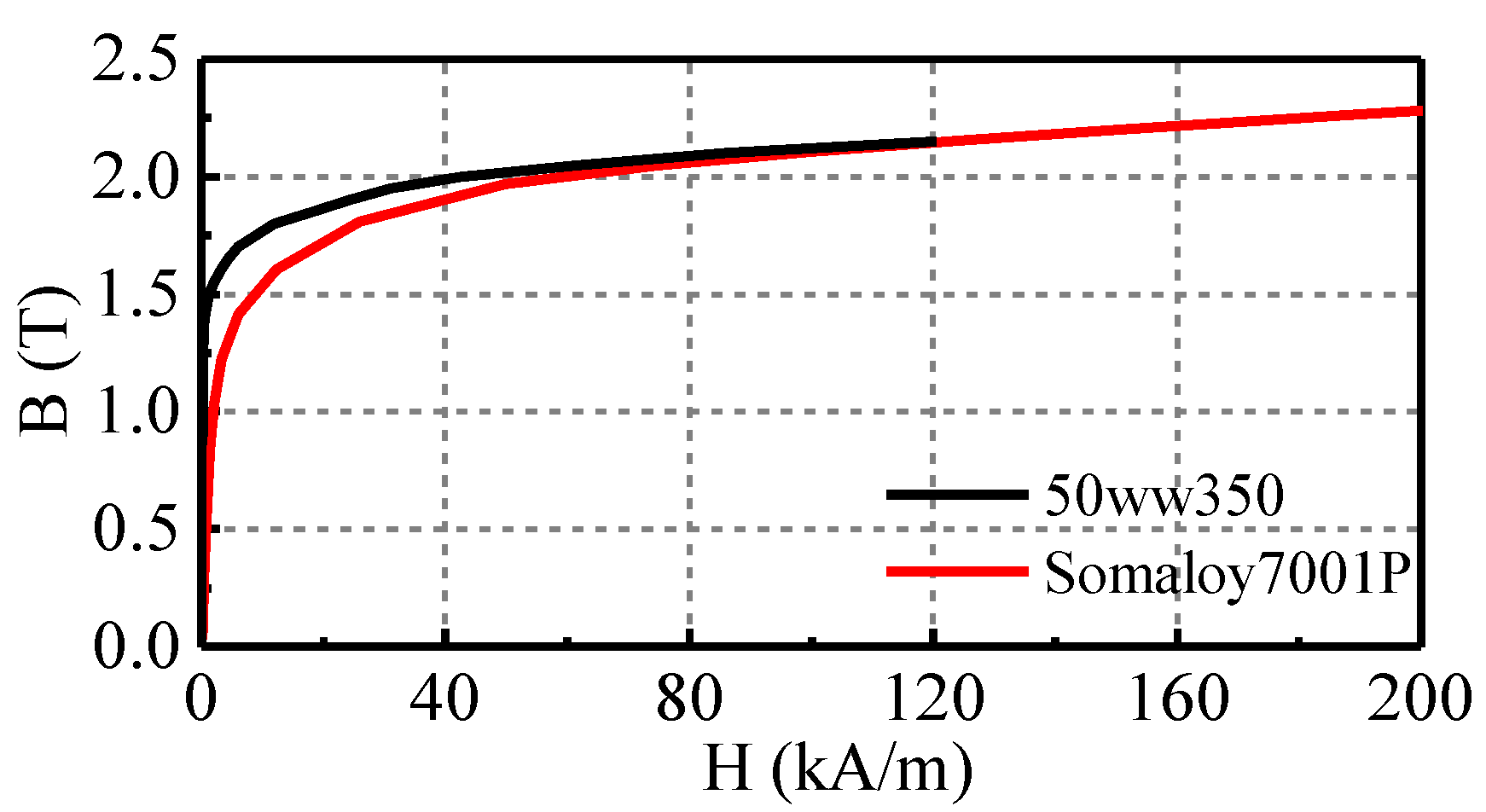
| Stator and rotor material | 50ww350 | ||
| FMP material | 50ww350 | 50ww350 | Somaloy700 |
| PM material | NdFeB38EH | NdFeB38EH | NdFeB38EH |
| Rated speed (rpm) | 600 | ||
| Rated current (A) | 20 | ||
| Current density (A/mm2) | 5 | ||
| Slot packing factor | 0.6 | ||
| Turns per slot | 40 | ||
| Winding resistance (Ω) | 0.088 | ||
| Items | M I | M II | M III |
|---|---|---|---|
| Average torque (Nm) | 94.0 | 104.5 | 119.7 |
| Torque ripple (Nm) | 1.52 (1.6%) | 1.70 (1.8%) | 1.47 (1.5%) |
| Power (kW) | 5.90 | 6.56 | 7.52 |
| Loss (W) | 412.4 | 442.2 | 572.5 |
| Efficiency | 93.5% | 93.7% | 92.9% |
| Weight (kg) | 12.88 | 14.86 | 15.76 |
| Torque density (Nm/kg) | 7.30 | 7.03 | 7.60 |
| Volume (L) | 5.54 | 5.54 | 5.54 |
| Torque density (Nm/L) | 16.97 | 18.86 | 21.61 |
© 2019 by the authors. Licensee MDPI, Basel, Switzerland. This article is an open access article distributed under the terms and conditions of the Creative Commons Attribution (CC BY) license (http://creativecommons.org/licenses/by/4.0/).
Share and Cite
Yu, D.; Huang, X.; Wu, L.; Fang, Y. Design and Analysis of Outer Rotor Permanent-Magnet Vernier Machines with Overhang Structure for In-Wheel Direct-Drive Application. Energies 2019, 12, 1238. https://doi.org/10.3390/en12071238
Yu D, Huang X, Wu L, Fang Y. Design and Analysis of Outer Rotor Permanent-Magnet Vernier Machines with Overhang Structure for In-Wheel Direct-Drive Application. Energies. 2019; 12(7):1238. https://doi.org/10.3390/en12071238
Chicago/Turabian StyleYu, Dong, Xiaoyan Huang, Lijian Wu, and Youtong Fang. 2019. "Design and Analysis of Outer Rotor Permanent-Magnet Vernier Machines with Overhang Structure for In-Wheel Direct-Drive Application" Energies 12, no. 7: 1238. https://doi.org/10.3390/en12071238
APA StyleYu, D., Huang, X., Wu, L., & Fang, Y. (2019). Design and Analysis of Outer Rotor Permanent-Magnet Vernier Machines with Overhang Structure for In-Wheel Direct-Drive Application. Energies, 12(7), 1238. https://doi.org/10.3390/en12071238