Article

A Supercapacitor-Based Method to Mitigate Overvoltage and Recycle the Energy of Pantograph Arcing in the High Speed Railway

Department of Electrical Engineering, The Hong Kong Polytechnic University, Hong Kong 999077, China
*
Author to whom correspondence should be addressed.
Energies 2019, 12(7), 1214; https://doi.org/10.3390/en12071214
Submission received: 23 December 2018 / Revised: 17 February 2019 / Accepted: 22 February 2019 / Published: 28 March 2019
(This article belongs to the Section B: Energy and Environment)

Abstract

:
The pantograph arcing phenomenon may shorten the service life of a pantograph and even destroy onboard devices and instruments, due to the irregular motions of the train and the intermittent line–pantograph disconnection. This paper points out that abrupt inductive energy from the magnetizing inductance of the traction transformer can lead to an electromagnetic transient process with unexpected overvoltage across it. Further, a supercapacitor-based power electronic system is proposed, which can not only redirect the inductive energy to the supercapacitor pack through bidirectional converters but also mitigate the overvoltage across the main electrical equipment when pantograph arcing occurs. Simulation results show the overvoltage could be reduced and the energy stored in the supercapacitor which could also be used to provide energy for sensors or other devices.

1. Introduction

In recent years, the high-speed railway (HSR) has been fully developed in most countries because of many unique advantages such as high speed, large transportation volume, high efficiency, and low pollution. In the traction system, the pantograph/catenary system is one of the key components which is the gateway of the train drawing the power from the power system [1]. However, one tough issue is that pantograph arcing could affect the performance of the catenary system, shortening the service life of the pantograph, damaging devices on the train, and even paralyzing the regional power system [2,3] since there will be high voltage difference and current surge. The DC component and abundant frequency harmonics will saturate the power transformer and propagate through a series of power electronics equipment on the train. Therefore, the arcing between the pantograph and the overhead line has been a crucial issue to the high-speed railway’s development.
Plenty of research has been devoted to the arcing issue. However, it is difficult to eliminate this pantograph arcing since the voltage and current levels are high and the relative motion between the pantograph and the overhead line cannot be avoided [4,5]. The present research around pantograph arcing has been focused on the analysis of the dynamic characteristic and the model of the arcing [6,7,8]. Ref [6] reviewed the past research progress of pantograph arcing from the different models, including the Cassie and Mayr’s and the hybrid arcing model. Numerical simulation is used to analyze the dynamic characteristics of pantograph arcing, for example, Gao and Hao [7,8] presented the mechanism of how heat dissipation and gas flow field influence the plasma behavior of arcing. Considering the influence of the pantograph/catenary detachment process on the train system, an effective extended black-box model of pantograph arcing is proposed in [9] by introducing a dynamic pantograph and the overhead line detachment trajectory model. Another resistive arc model is proposed for investigating the interaction between the arc and the remaining part of the electronic circuit [10]. The arcing implies a large transient and the damage to the contact point [11,12,13]. The waveform of the pantograph arcing looks like high-frequency pulse width modulation and such a transient process could last for a fraction of a second [14]. The electromagnetic radiated interference caused by pantograph–catenary arcing has been analyzed, and solutions in the arcing detection method and the sensitivity to components have been presented [15,16,17]. A laboratory test platform was built to verify both the arcing characteristic and the detection method [18,19,20].
Pantograph arcing can result in voltage surge to the locomotive electrical equipment and has become one of the potential safety issues of the railways. Some literature involves the suppression of the overvoltage across the electrical equipment. Ref. [21] adopts a transient voltage suppressor to protect the pulse-width modulation (PWM) encoder from overvoltage and guarantee the normal operation of the control systems. The overvoltage caused by the action of the spilt-phase breaker during the electromagnetic transient process of the automatic passing neutral section was analyzed in [22] and an approach to restraining the overvoltage put forward. Ref. [23] utilizes the surge arrestor to protect the system against lightning overvoltage. Ref. [24] can suppress the overvoltage caused by pantograph arcing by paralleling a capacitance in the high-voltage side of the traction transformer, but it fails to provide detailed design of such a capacitance in practice. Different from ref. [21], this paper focuses on protecting the main electrical equipment of the traction drive system including the transformer and the back-end converters. This paper analyzes the mechanism of the overvoltage phenomenon of the pantograph arcing and provides an approach to overcome it. Bidirectional converters and a supercapacitor system are employed to absorb the inductive energy from arcing. An energy recycling system was built by multiple supercapacitor-based energy balancing subsystems which could bear the high voltage and current.

2. Overvoltage Phenomenon of Pantograph Arcing

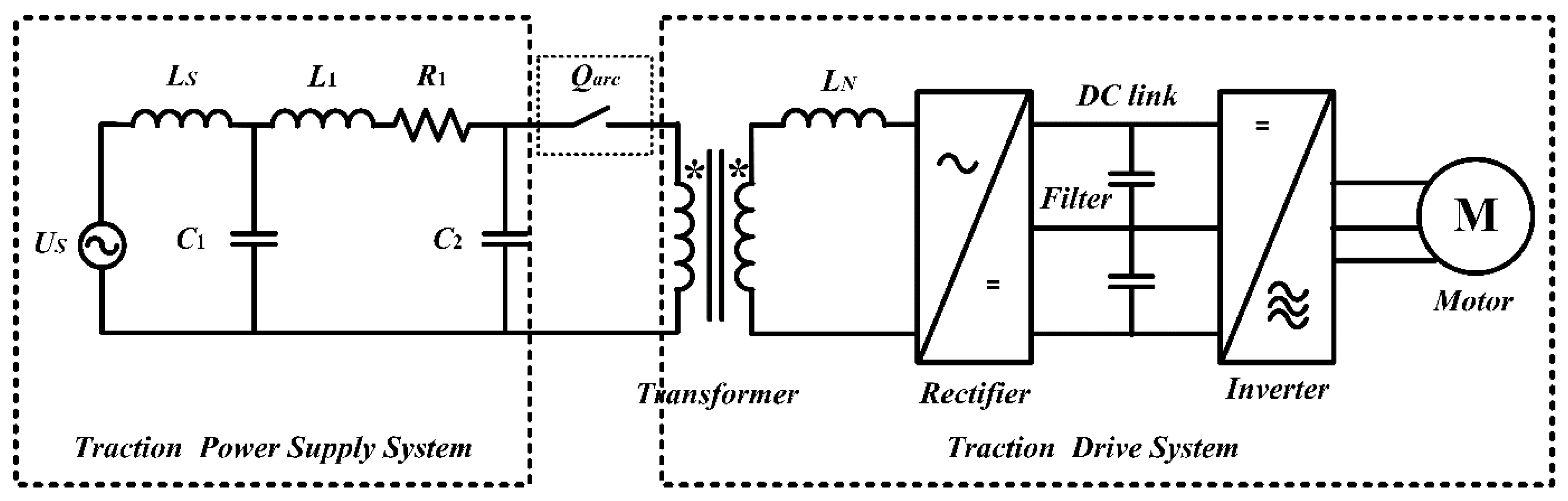
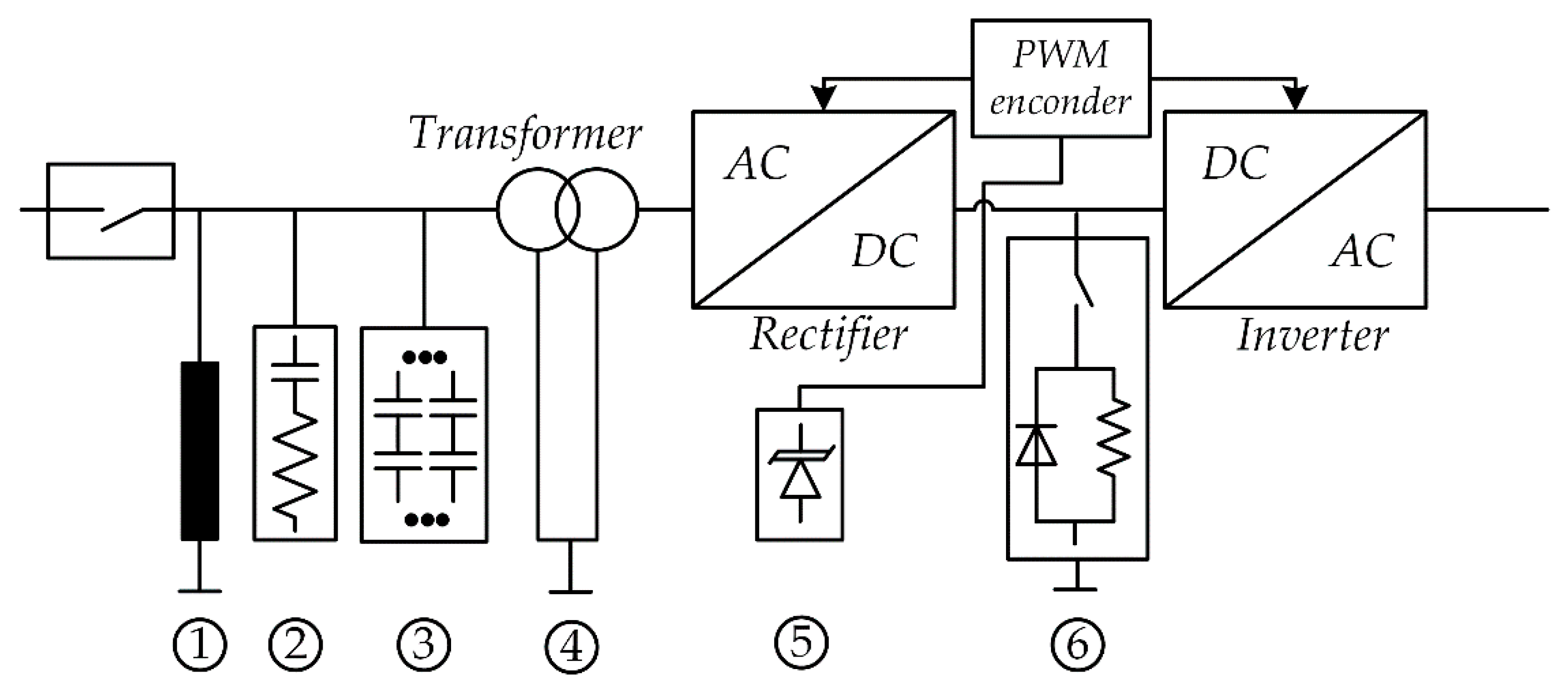
2.1. Description of the Traction System

Figure 1 is the equivalent circuit of the whole traction system composed of the power supply system and the locomotive drive system. Wherein, Us denotes the traction substation voltage, Ls denotes the equivalent inductance of the traction substation, R1, L1, C1, C2 are the π -type equivalent parameters of the transmission line. Qarc denotes the pantograph/catenary arcing which is represented by the Cassie arcing model in this paper. The traction drive system includes the single-phase locomotive transformer, traction converters, and induction motors. When the train is running, the pantograph obtains single-phase energy from the overhead catenary line and transmits it to the locomotive set-down transformer, the three-level PWM rectifier, and the three-phase inverter. The inverter with the adjustable output voltage and frequency supplies power for the induction motors.

2.2. Model of the Pantograph Arcing

As mentioned in ref. [22], the process of pantograph arcing includes the start of arcing, the unstable establishment of the arc, the stable combustion of the arc, the unstable period before the arc’s extinction, and the extinction of the arc. In the running train, since stochastic irregularity detachment leads to different gap lengths and arc shapes between the pantograph and the overhead line, there may be two modes for the pantograph arcing, one is that the arc remains burning while the other is that the arc is extinguished [26]. When the arc remains burning during the detachment time, the arc waveforms have characteristics of distorted voltage and sinusoidal current with several zero-crossing points in each half cycle. When the arc extinguishes, it will not reignite unless the pantograph–catenary gap decreases to a threshold value and is broken down again. In this paper, the Cassie arc model was adopted to validate the electrical properties of pantograph acing [27]. The Cassie is defined as
d g d t = 1 τ ( i c 2 u c 2 g ) g .
where g and τ are the conductance and time constant of the Cassie arc model respectively, i c and u c are the arc current and arc voltage respectively.

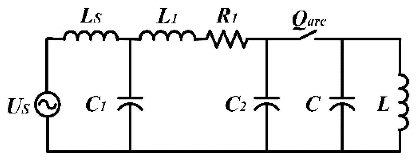
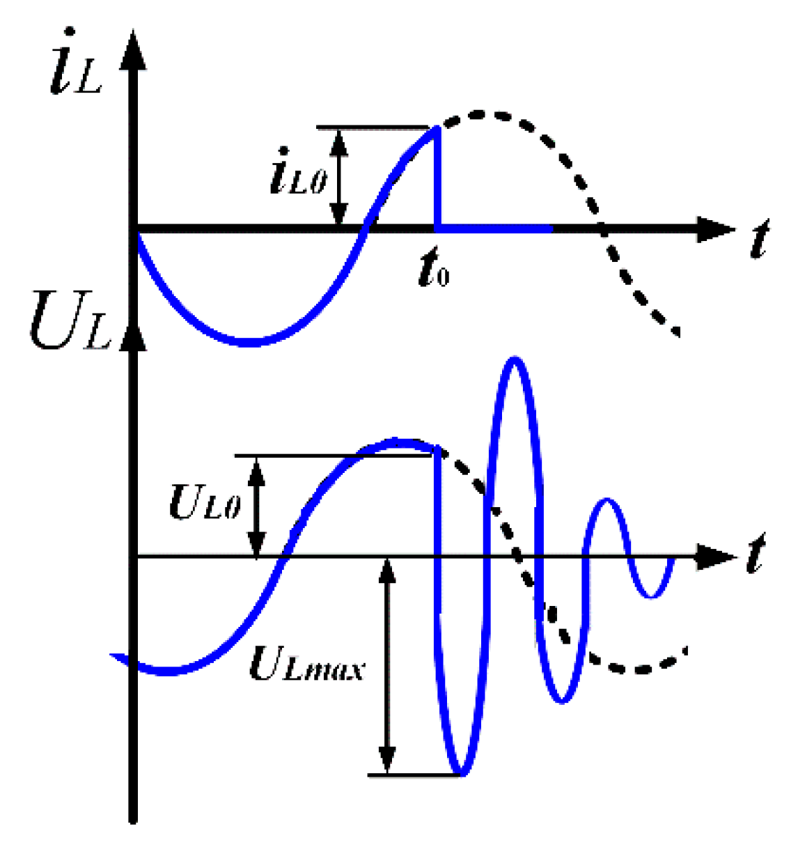
2.3. Mechanism of the Overvoltage Phenomenon of the Pantograph Arcing

The occurrence of pantograph arcing becomes a severe issue as the increase in the running speed, and the sudden cut-off of the arcing current leads to an electromagnetic transient process in the locomotive electrical equipment. It can be seen from Figure 1 that the pantograph is connected with the locomotive transformer. A simplified equivalent circuit is illustrated in Figure 2, where L denotes the magnetizing inductance of the locomotive transformer and C denotes the transformer equivalent capacitance to ground. It is noticeable that under the normal situation of the running traction vehicle, the current through C is very small. When the pantograph arcing is cut off suddenly at the time instant t 0 , the magnetizing current i L 0 drops to zero in a very short time. According to U L = L d i L d t , the magnetizing current mutation produces overvoltage across the transformer. In other words, at this moment, the magnetic field energy stored in the magnetizing inductance L is
W L = 1 2 L i L 0 2 .
and the electric field energy stored in the C is
W C = 1 2 C U L 0 2 .
When the arcing current extinguishes, the magnetizing current i L 0 suddenly drops to zero, and oscillation occurs between L and C . Since the value of the capacitance C is very small, a huge voltage surge can be detected when all of the magnetic field energy W L is transferred into the electric field energy W C . The maximum value of the overvoltage U L max can be determined as
W L + W C = 1 2 C U L max 2 .
Substitution of (2) and (3) into (4) leads to
U L max = U L 0 2 + L C i L 0 2 .
Figure 3 illustrates the waveform when the pantograph arcing current is cut off at t 0 . Since the locomotive transformer is equivalent to an inductive load, the extinguishment of the arcing current can cause overvoltage in the transformer primary side. Such overvoltage may last for one period (i.e., 0.0.2 s). Meanwhile, such an overvoltage wave can spread to the whole traction system, thus threatening the insulation of the locomotive equipment. Therefore, effective measures must be taken to prevent overvoltage resulting from the pantograph arcing extinguishment.

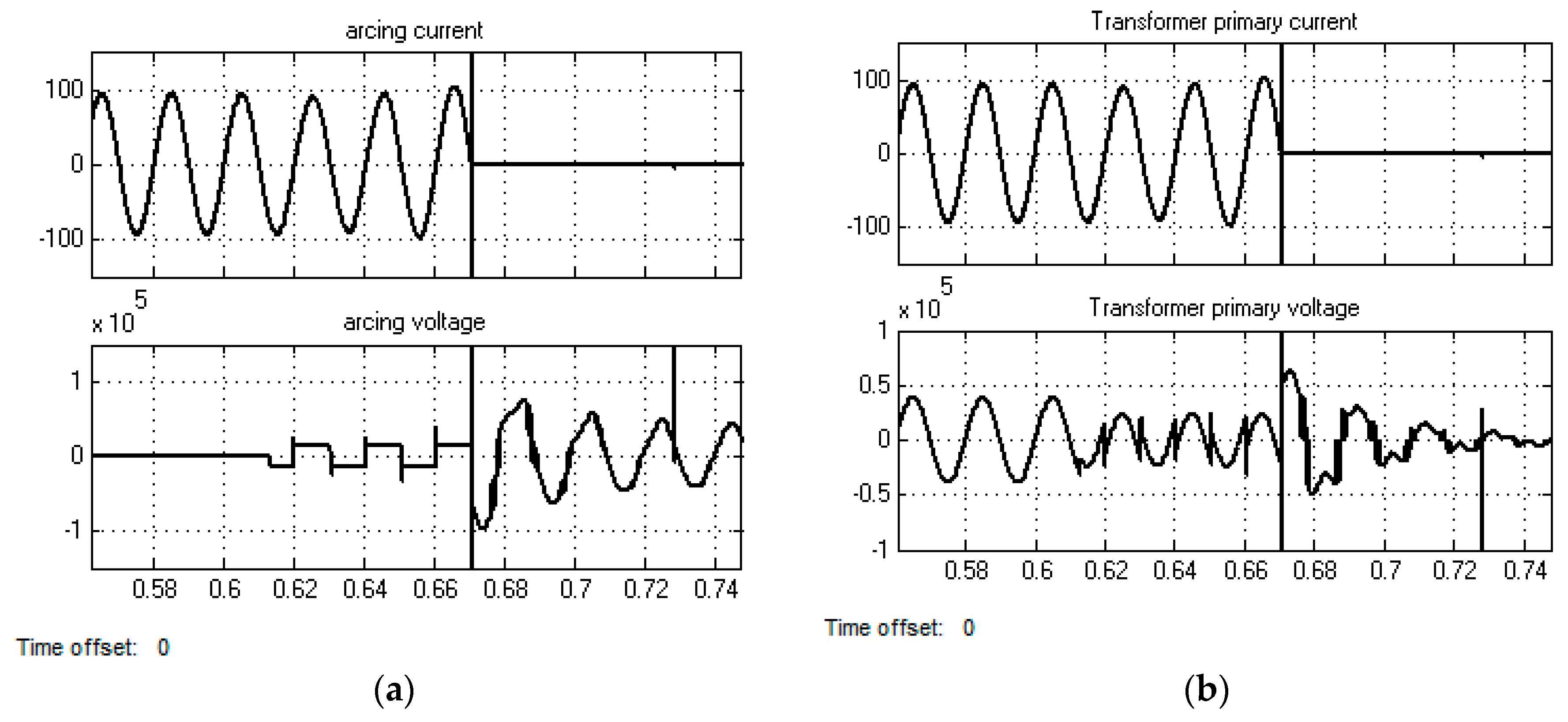
2.4. Simulation of the Overvoltage Phenomenon of Pantograph Arcing

The simulation schematic circuit is implemented by Matlab Simulink as shown in Figure 1. Considering the operating conditions in practice for the CRH2 high speed railways, the parameters of the traction power supply system are adopted the same as in ref. [25], which is Us = 27.5 kV rms, Ls = 31.8 mH, R1 = 2.95 Ω, L1 = 23.5 mH, C1 = C2 = 0.081 μF. The turns ratio of the locomotive transformer is set to be 25 kV:1.5 kV, the DC link voltage is 3 kV, the DC link filter capacitors are set to be 0.016 F. The time instant of the pantograph–catenary disconnection is set to be at 0.613 s.
The simulation results of the pantograph arcing and transformer waveforms are shown in Figure 4. The whole system operates stably until the pantograph–catenary disconnection occurs at 0.613 s. The pantograph–catenary arcing occurs immediately and exists until 0.67 s. The arcing current drops to zero and is cut-off at 0.67 s. Notice that before the arcing current extinguishes, the value of the arcing current is equal to the sum of the magnetizing current and the load current reflected from the secondary side. In other words, although the arcing current drops to zero at 0.617 s, the magnetizing current is nonzero at this moment. The abrupt change of the circuit leads to resonance between the magnetizing inductance and stray capacitance, thus causing overvoltage across the transformer. As observed in Figure 4b, the maximum overvoltage can be about 6 kV. Hence, the extinguishment of the pantograph arcing can cause 1.7 times overvoltage across the transformer. The duration of the transient process is about two periods (0.04 s). But in the actual situation, since the pantograph–catenary detachment is frequent, the overvoltage can be a continuous potential problem for the safe operation of the locomotive equipment.

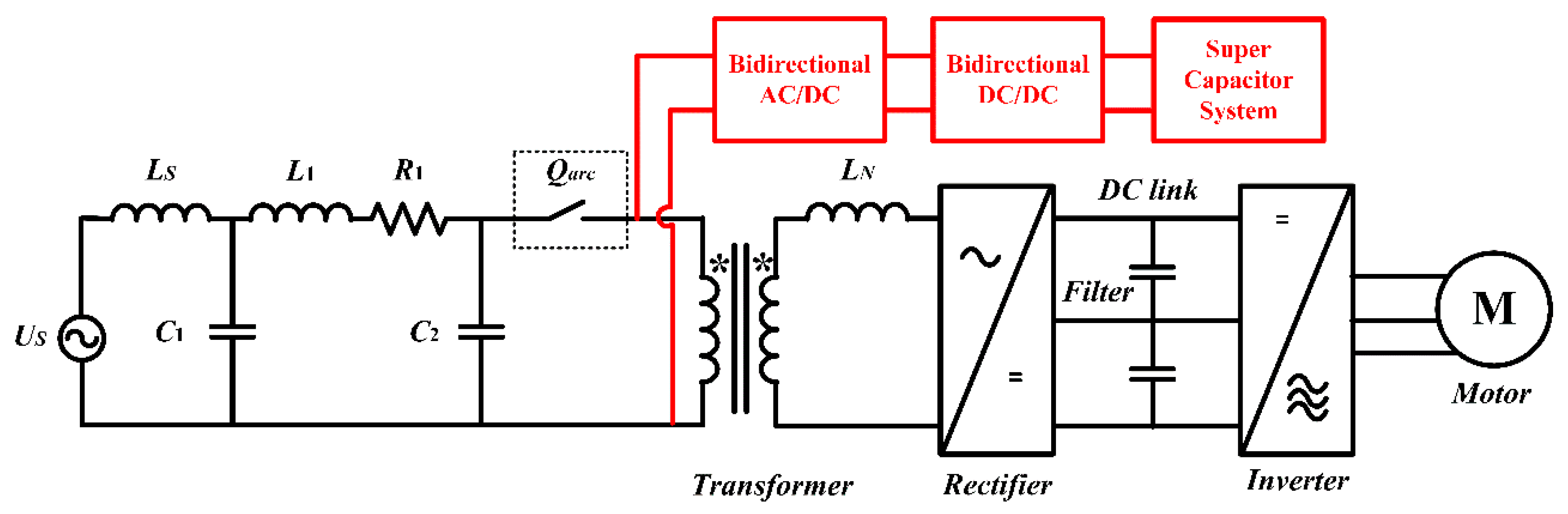
3. Proposed Method to Mitigate the Overvoltage

3.1. Proposed Circuit

From the previous analysis, since the characteristic of the traction transformer is inductive, the overvoltage occurs when the pantograph arcing current is cut off. It can be seen from (5) that we can increase the capacitance C in the primary side of the transformer to reduce the overvoltage. In order to suppress the overvoltage of the pantographs arcing and absorb the inductive energy, a supercapacitor-based power electronic system is proposed as shown in Figure 5, consisting of a bidirectional AC/DC converter, bidirectional DC/DC converter and a supercapacitor system.

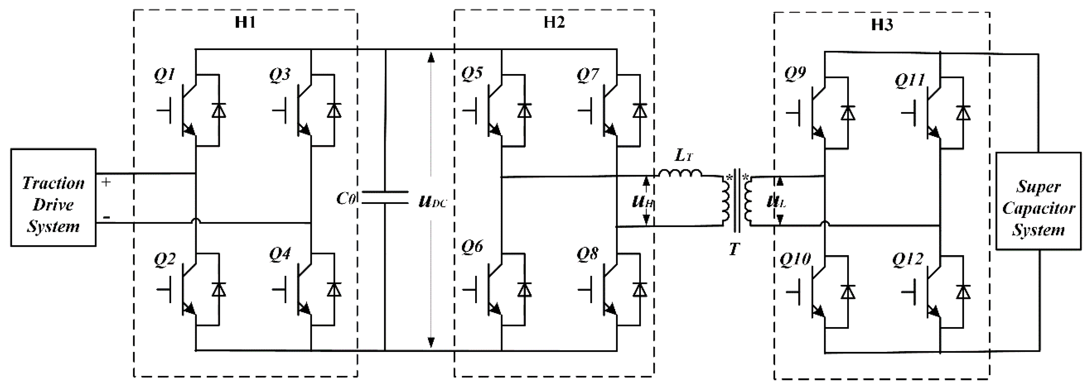
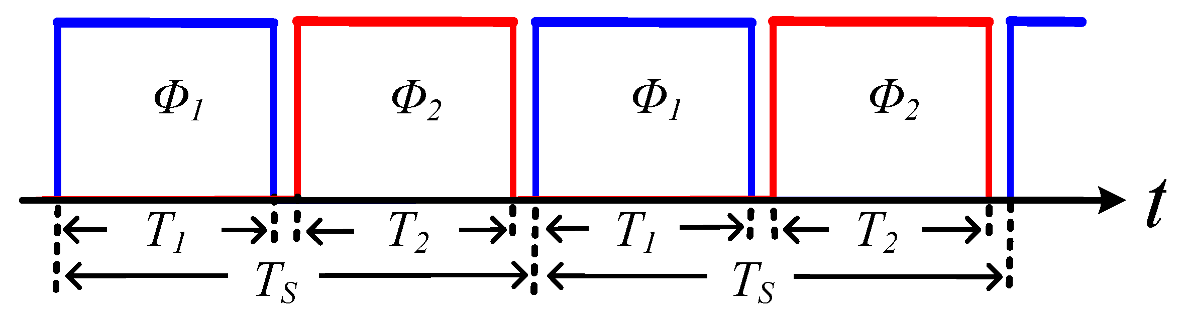
3.2. Bidirectional Converter

Figure 6 shows the schematic circuit of the bidirectional PWM converter composed of three H-bridges (H1, H2, and H3), dc-link capacitor C0, high-frequency inductance LT, transformer T, and the supercapacitor system. Wherein, u D C is the DC-link voltage, u H and u L are the AC square wave with 50% duty ratio. There are two operating modes of the bidirectional converter. The first one is the charging mode when energy flows from the overhead line to the supercapacitor system. The H1 bridge operates as a rectifier (AC–DC), the H2 and H3 bridges operate as a step-down DC–DC converter. The other is the discharging mode when energy flows from the supercapacitor system to the traction drive system. The H2 and H3 bridges operate as a step-up DC–DC converter while the H1 bridge operates as an inverter. At this time, the magnetizing inductance current of the traction transformer is controlled so as to be constantly continuous in order to prevent its mutation.

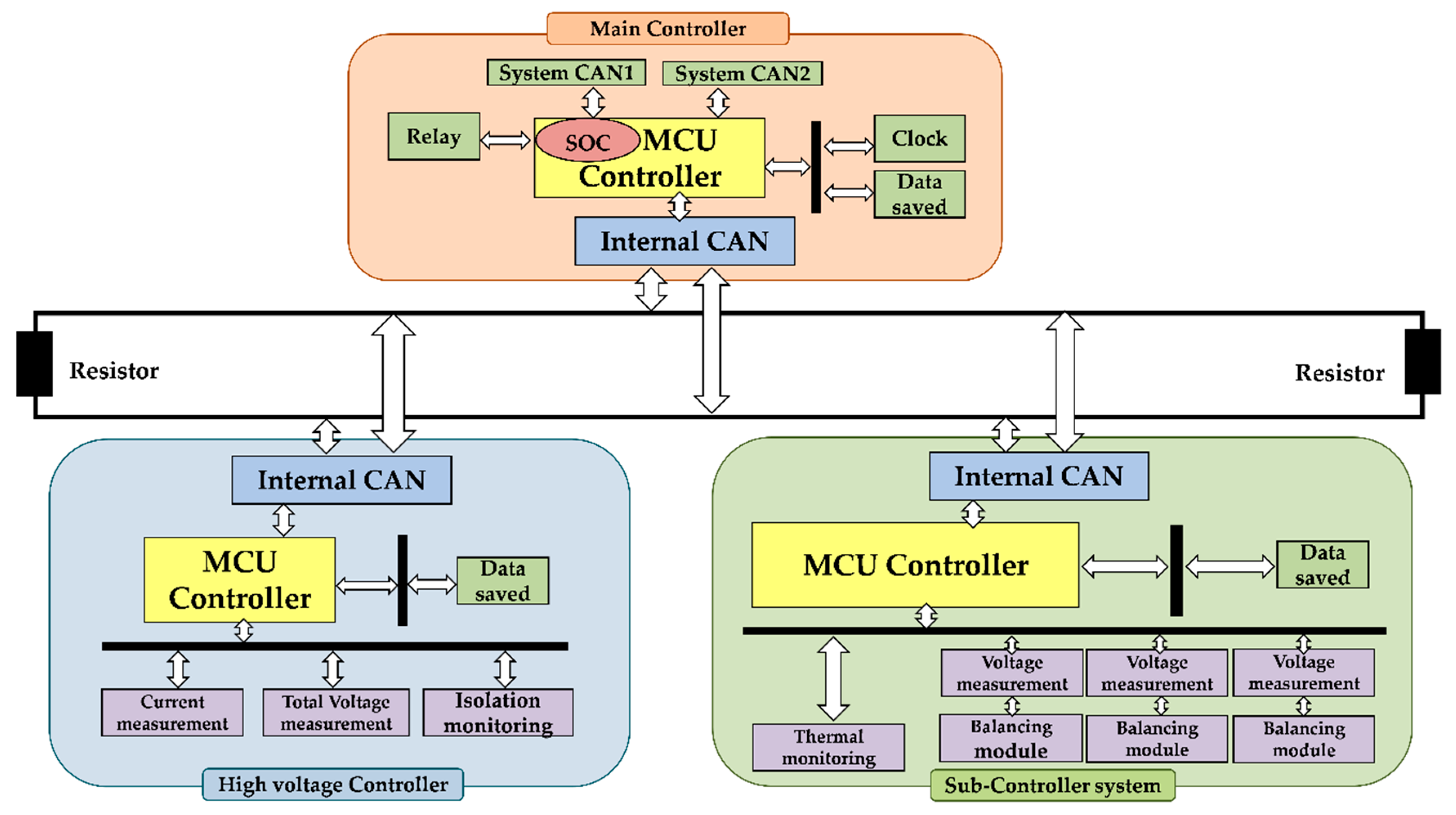
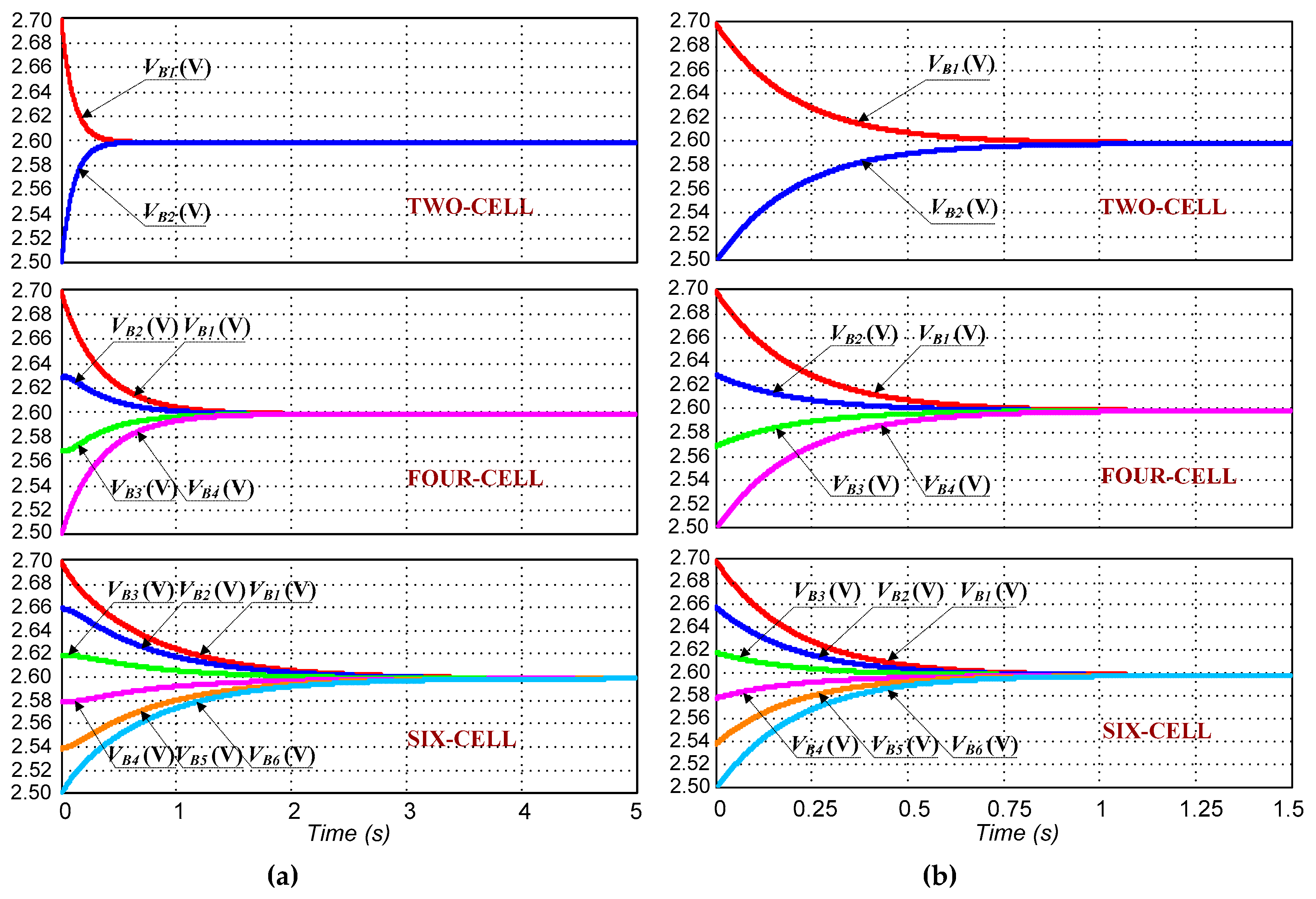
3.3. Supercapacitor-Based Energy Storage System

The supercapacitor-based energy management system mainly consists of the energy storage calculation unit, supercapacitor unit, parameter detection, as well as the monitoring of the supercapacitor units and the voltage automatic equalization circuit. The functional block diagram and system structure are shown in Figure 7.
In order to achieve small internal impedance, high voltage, and high current, a large number of supercapacitor modules should be connected in series and in parallel. However, the uneven performance of each supercapacitor will cause an imbalance of voltage when the supercapacitors are charging and discharging. Hence, the switched capacitor voltage equalizer is used by directly charging the supercapacitor cells with lower voltage by the supercapacitor module with higher voltage. The conventional switched capacitor voltage equalizer, as shown in Figure 8a, is not suitable for this system because the balancing time and settling time increase as the number of supercapacitor modules increases. In this paper, an improved balancing system was developed as shown in Figure 8b. Figure 9 is the control strategy of the voltage balancing system, where all switches are controlled by a set of complementary pulse signals with a fixed frequency and duty cycle of 0.5. Compared to conventional structures, it is obvious that the balancing speed is higher since higher voltage capacitor cells can charge lower voltage cells.
As shown in Figure 10, the balancing time increases as the number of supercapacitor modules increase in the conventional switched capacitor balancing system. However, the balancing time shown in Figure 10b does not change when the supercapacitor cell modules increase. Therefore, the performance of the improved balancing system is significantly superior to the traditional switched capacitor balancer.
Table 1 presents the parameters of supercapacitor system for the proposed method. The whole system employs 2280 supercapacitor cells each of which has a capacity of 360 F and a rated voltage of 2.7 V. After connecting the supercapacitor cell in series and in parallel, the whole energy storage system is expected to have a capacity of 15.5 F and a rated voltage of 550 V and can provide 30 kW instantaneous power support. According to the selling price from the official website of Man Yue Technology Holdings Limited, each supercapacitor cell is about 40 HKD, hence the total economic cost of the supercapacitor system should reach at least 91200 HKD (i.e., 2280 × 40 = 91200). The economy cost of the supercapacitor system is not actually cheap. Especially when the supercapacitor system is also used as the backup traction power supply, a large supercapacitance is required.

3.4. Simulation Results of the Proposed Circuit

The simulation circuit implemented by Matlab Simulink is shown in Figure 5. To validate the effectiveness of the proposed method, the same parameters are adopted as those in Section 1. Figure 11 shows the simulated waveforms of the proposed improved system. Similarly, the time instant for the pantograph–catenary disconnection is set at 0.613 s. The oscillation arcing current decays to zero gradually before extinguishment. The arcing extinguishes and will not ignite because of insufficient input energy. It can be seen that there is no lasting overvoltage on the primary side of the transformer. That is because the proposed method can absorb the inductive energy of the transformer magnetizing inductance to the supercapacitor system. The comparison of Figure 4 and Figure 12 validate the feasibility of the proposed method.

4. Performance Comparisons with Other Methods

Figure 12 illustrates several methods for overvoltage mitigation in the traction system where the surge arresters, RC absorption circuit, and the proposed method can be installed at the primary side of the transformer, the protective grounding is installed below the car body, the transient voltage suppressor is in parallel with the sensitive components in the PWM encoder, and the crowbar circuit is installed at the DC link of the converter. Different protection devices installed at different positions demonstrate unique features of overvoltage mitigation. A detailed comparison of the protection characteristic is sketched in Table 2. The surge arrester and RC absorption circuit can mitigate the lightning and switching overvoltage and there still exists severe residual voltage. The RC absorption circuit will consume electric power across the resistor even in normal operation. The proposed method can control the charging–discharging status of the supercapacitor system and recycle the inductive energy of the transformer through the PWM converter, which has very small settling time and provides enough instantaneous power compensation. Thus, the supercapacitor system can also be useful to face the voltage fluctuation of the traction power supply. The crowbar circuit can only protect the inverter and the motor from braking overvoltage. The proposed method can also provide a simple way to regenerate the braking energy by using the overvoltage features of the motor and by charging–discharging excessive power to the supercapacitor system. Besides, the supercapacitor system can also be used to provide energy for locomotive sensors or other devices. However, the proposed method is economically costly. Considering the insulation damage and safety issues of pantograph arcing, the economic cost is more acceptable than resultant safety costs.

5. Conclusions

Pantograph arcing extinguishment can cause a rapid change of current through the locomotive transformer inductance coil, which results in a voltage surge and damage to the insulation of the after equipment. This paper proposed a supercapacitor-based energy system to absorb the inductive arcing energy after connecting bidirectional PWM converters. The key part is to design a supercapacitor energy management system with a switched capacitor balancing cell. Simulation further validates the effectiveness and feasibility of the proposed system. The proposed supercapacitor system can also provide instantaneous power compensation to overcome the voltage fluctuation of the traction power supply and recycle the braking energy.

Author Contributions

Conceptualization, K.W.E.C. and C.X.; methodology, Z.C. and C.X.; software, Z.C. and X.W.; validation, H.F.H. and Z.C.

Funding

This research was funded by the Hong Kong Branch of the National Rail Transit Electrification and Automation Engineering Technology Research Centre, grant number 1-BBV1.

Acknowledgments

The authors gratefully acknowledge the financial support of the Hong Kong Branch of the National Rail Transit Electrification and Automation Engineering Technology Research Centre 1-BBV1.

Conflicts of Interest

The authors declare no conflict of interest.

References

  1. Wu, G.; Wu, J.; Wei, W.; Zhou, Y.; Yan, Z.; Gao, G. Characteristics of the Sliding Electric Contact of Pantograph/Contact Wire Systems in Electric Railways. Energies 2018, 11, 17. [Google Scholar]
  2. Tellini, B.; Macucci, M.; Giannetti, R.; Antonacci, G.A. Conducted and Radiated Interference Measurements in the Line-Pantograph System. IEEE Trans. Instrum. Meas. 2001, 50, 1661. [Google Scholar] [CrossRef]
  3. Wang, W.G.; Wu, G.N.; Gao, G.Q.; Wang, B.; Cui, Y.; Liu, D.L. The Pantograph-catenary Arc Test system for High-speed Railways. J. China Railw. Soc. 2012, 30, 22. [Google Scholar]
  4. Midya, S.; Bormann, D.; Larsson, A.; Schutte, T.; Thottappillil, R. Understanding pantograph arcing in electrified railways—Influence of various parameters. In Proceedings of the 2008 IEEE International Symposium on Electromagnetic Compatibility, Detroit, MI, USA, 18–22 August 2008; pp. 1–6. [Google Scholar]
  5. Lu, Y.T.; Chen, G.X.; Yang, H.J.; Zhang, S.D. Effect of the Inclination Angle of a Carbon Strip on Friction and Wear Behavior of Carbon Strip /Pure Copper Contact Wire at a High Speed. Lubrication Eng. 2011, 36, 19–22. [Google Scholar]
  6. Wang, Y.; Liu, Z.G.; Fan, F.Q.; Gao, S.B. Review of Research Development of Pantograph-catenary Arc Model and Electrical Characteristics. J. China Railw. Soc. 2013, 35, 35–43. [Google Scholar]
  7. Gao, G.; Hao, J.; Wei, W.; Hu, H.; Zhu, G.; Wu, G. Dynamics of Pantograph–Catenary Arc During the Pantograph Lowering Process. IEEE Trans. Plasma Sci. 2016, 44, 11. [Google Scholar] [CrossRef]
  8. Hao, J.; Gao, G.; Wu, G. Dynamic Analysis of Pantograph-catenary Arc During the Pantograph Lowering Process. In Proceedings of the 2016 IEEE International Conference on High Voltage Engineering and Application (ICHVE), Chengdu, China, 19–22 September 2016. [Google Scholar]
  9. Liu, Z.; Zhou, H.; Huang, K.; Song, Y.; Zheng, Z.; Cheng, Y. Extended Black-Box Model of Pantograph-Catenary Detachment Arc Considering Pantograph-Catenary Dynamics in Electrified Railway. IEEE Trans. Ind. Appl. 2019, 55, 776–785. [Google Scholar] [CrossRef]
  10. Galdi, V.; Ippolito, L.; Piccolo, A. Arcing in AC railways: A mathematical approach. WIT Trans. Built Environ. 1998, 37. [Google Scholar] [CrossRef]
  11. Peng, K.; Gao, G. The Influence of Power Factor and Traction Current on Pantograph-catenary Arc Energy. In Proceedings of the 2016 IEEE International Conference on High Voltage Engineering and Application (ICHVE), Chengdu, China, 19–22 September 2016. [Google Scholar]
  12. Ma, L.; Marvin, A.; Karadimou, E.; Armstrong, R.; Wen, Y. An Experimental Programme to Determine the Feasibility of Using a Reverberation Chamber to Measure the Total Power Radiated by an Arcing Pantograph. In Proceedings of the 2014 International Symposium on Electromagnetic Compatibility (EMC Europe 2014), Gothenburg, Sweden, 1–4 September 2014. [Google Scholar]
  13. Ma, L.; Wen, Y.; Marvin, A.; Karadimou, E.; Armstrong, R.; Cao, H. A Novel Method for Calculating the Radiated Disturbance from Pantograph Arcing in High-Speed Railway. IEEE Trans. Veh. Technol. 2017, 66, 10. [Google Scholar] [CrossRef]
  14. Wei, W.; Wu, J.; Gao, G.; Gu, Z.; Liu, X.; Zhu, G.; Wu, G. Study on Pantograph Arcing in a Laboratory Simulation System by High-Speed Photography. IEEE Trans. Plasma Sci. 2016, 44, 10. [Google Scholar] [CrossRef]
  15. Geise, R.; Kerfin, O.; Neubauer, B.; Zimmer, G.; Enders, A. EMC Analysis Including Receiver Characteristics -Pantograph Arcing and the Instrument Landing System. In Proceedings of the 2015 IEEE International Symposium on Electromagnetic Compatibility (EMC), Dresden, Germany, 16–22 August 2015. [Google Scholar]
  16. Radojević, Z.M.; Terzija, V.V.; Djuric, M.B. Numerical Algorithm for Overhead Lines Arcing Faults Detection and Distance and Directional Protection. IEEE Trans. Power Deliv. 2000, 15, 1. [Google Scholar] [CrossRef]
  17. Gao, G.; Yan, X.; Yang, Z.; Wei, W.; Hu, Y.; Wu, G. Pantograph–Catenary Arcing Detection Based on Electromagnetic Radiation. IEEE Trans. Electromagn. Compat. 2018, 99, 1–7. [Google Scholar] [CrossRef]
  18. He, D.H. Test Method of Arcing Behaviour for Railway Current Collection System. In Proceedings of the World Congress on Railway Research, Cologne, Germany, 25–29 November 2001. [Google Scholar]
  19. Kim, W.-I.; Lee, K.-S.; Jung, N.-G.; Koo, K.-W.; Kim, J.-M. Analysis of the Pantograph Arcing on the Railway Vehicle. In Proceedings of the 20th International Conference on Electrical Machines and Systems (ICEMS), Sydney, NSW, Australia, 11–14 August 2017; pp. 1–4. [Google Scholar]
  20. Xu, C.D.; Cheng, K.W.E.; Zou, Y.; Wang, X.L.; Raman, S.R.; Xue, X.D. Electromagnetic Scattering of High Power Traction Transformer in High Speed Railway Based on FEM. In Proceedings of the 2016 International Symposium on Electrical Engineering (ISEE), Hong Kong, China, 14 December 2016. [Google Scholar]
  21. Lu, H.; Zhu, F.; Liu, Q.; Li, X.; Tang, Y.; Qiu, R. Suppression of cable overvoltage in a high-speed Electric multiple units system. IEEE Trans. Electromagn. Compat. 2018, 99, 1–11. [Google Scholar] [CrossRef]
  22. Wang, Q.; Zhu, F.; Liu, Q.; Li, X.; Tang, Y.; Qiu, R. Transient overvoltage study of auto-passing neutral section in high-speed railway, Transportation Electrification Asia-Pacific (ITEC Asia-Pacific). In Proceedings of the 2017 IEEE Conference and Exp, Harbin, China, 7–10 August 2017. [Google Scholar]
  23. Achouri, F.; Achouri, I.; Khamliche, M. Protection of 25Kv electrified railway system. In Proceedings of the 2015 4th International Conference on Electrical Engineering (ICEE), Boumerdes, Algeria, 13–15 December 2015; pp. 1–6. [Google Scholar]
  24. Li, T.; Wu, G.; Zhou, L.; Gao, G.; Wang, W.; Wang, B.; Liu, D.; Li, D. Pantograph arcing’s impact on locomotive equipment. In Proceedings of the 2011 IEEE 57th Holm Conference on Electrical Contacts (Holm), Minneapolis, MN, USA, 11–14 September 2011; pp. 1–5. [Google Scholar]
  25. Wang, W.G. Experimental study on electrical characteristics of pantograph arc. Low Voltage Elect. App. 2012, 6, 5–10. [Google Scholar]
  26. Gao, G.; Zhang, T.; Wei, W.; Hu, Y.; Wu, G.; Zhou, N. A pantograph arcing model for electrified railways with different speeds. J. Rail Rapid Transit 2018, 232, 1731–1740. [Google Scholar] [CrossRef]
  27. Habedank, U. On the mathematical-description of arc behavior in the vicinity of current zero. EtzArchiv 1988, 10, 339–343. [Google Scholar]
  28. Deblecker, O.; Bertrand, P.; Versèle, C. Study of auxiliary railway power supply facing catenary transient overvoltage. In Proceedings of the 2009 35th Annual Conference of IEEE Industrial Electronics, Porto, Portugal, 3–5 November 2009. [Google Scholar]
  29. Delfino, F.; Procopio, R.; Rossi, M. Overvoltage protection of light railway transportation systems. In Proceedings of the 2003 IEEE Bologna Power Tech Conference Proceedings, Bologna, Italy, 23–26 June 2003; Volume 4. [Google Scholar]
  30. Yusu, W.; Liu, Y.; Gao, G.; Wu, G. Influence of grounding mode on surge voltage in the process of pantograph rising for high speed train. In Proceedings of the 2016 IEEE International Conference on High Voltage Engineering and Application (ICHVE), Chengdu, China, 19–22 September 2016. [Google Scholar]
Figure 1. The structure of the traction system [25].
Energies 12 01214 g001
Figure 2. Simplified equivalent circuit for the traction system.
Energies 12 01214 g002
Figure 3. Transformer transient waveform when the pantograph arcing current extinguishes.
Energies 12 01214 g003
Figure 4. Simulation result of the overvoltage phenomenon. (a) The current and voltage waveforms between the pantograph and catenary. (b) The current and voltage waveforms of the transformer primary side.
Energies 12 01214 g004
Figure 5. The proposed circuit configuration with bidirectional converters connected with the super capacitor-based energy storage system.
Energies 12 01214 g005
Figure 6. The schematic circuit of the PWM bidirectional converter.
Energies 12 01214 g006
Figure 7. Functional block diagram of the supercapacitor-based energy management system.
Energies 12 01214 g007
Figure 8. Supercapacitor module with switched capacitor balancing cell (a) traditional version (b) improved version.
Energies 12 01214 g008
Figure 9. Time control strategy of the voltage balancing system.
Energies 12 01214 g009
Figure 10. Supercapacitor based energy balancing system simulation waveform: (a) traditional version; (b) Improved version.
Energies 12 01214 g010
Figure 11. Simulation result of the proposed method. (a) The current and voltage waveforms of the Cassie arcing model. (b) The current and voltage waveforms of the transformer primary side.
Energies 12 01214 g011
Figure 12. Protection methods for overvoltage mitigation wherein : Surge arresters. : RC absorption circuit. : Proposed method. : Grounding. : Transient Voltage Suppressor. : Crowbar circuit.
Energies 12 01214 g012
Table 1. Parameters of the supercapacitor system.
Each supercapacitor capacity350 F
Number of supercapacitor cells2280
Supercapacitor internal resistance8 mΩ
Supercapacitor rated voltage550 V
Supercapacitor initial voltage530 V
Table 2. Features of several methods for the overvoltage suppressor.
ReferenceMethodsFeatures
[28]Crowbar circuita. Protect the auxiliary railway power supply from catenary transient overvoltage.
b. Behaves like a voltage limiter within a prescribed hysteresis band.
[29]Surge arrestersa. Protect the systems from lightening overvoltage and switching overvoltage.
b. Dependent on the value of their earth resistance.
[30]Groundinga. Mitigates the voltage surge across a car-body, especially through paralleling the capacitance besides grounding the resistors.
[21]Transient voltage suppressor (TVS)a. Adopt the TVS to suppress the overvoltage in a high-speed electric multiple units system excited by pantograph arcing and traction current flowing through the train body.
[24]Resistor-capacitor (RC) absorption circuita. Protect the systems from high frequency switching transient overvoltage.
b. Dissipate electric power during normal operation.
Proposed MethodSupercapacitor systemsa. Adsorb the excessive inductive energy of the locomotive transformer.
b. Provide instantaneous power compensation to overcome the voltage fluctuation of the traction power supply.

