Article

Reliability, Availability and Maintainability Analysis for Grid-Connected Solar Photovoltaic Systems

1
Electrical power and Machines department, the higher Institute of Engineering, El’Shorouk 11837, Egypt
2
Electrical power and Machines department, Faculty of Engineering, Ain Shams University, Cairo 11566, Egypt
3
Electrical power and Machines department, Faculty of Engineering, Cairo University, Giza 12613, Egypt
*
Author to whom correspondence should be addressed.
Energies 2019, 12(7), 1213; https://doi.org/10.3390/en12071213
Submission received: 28 February 2019 / Revised: 19 March 2019 / Accepted: 22 March 2019 / Published: 28 March 2019

Abstract

:
Recently, solar power generation is significantly contributed to growing renewable sources of electricity all over the world. The reliability and availability improvement of solar photovoltaic (PV) systems has become a critical area of interest for researchers. Reliability, availability, and maintainability (RAM) is an engineering tool used to address operational and safety issues of systems. It aims to identify the weakest areas of a system which will improve the overall system reliability. In this paper, RAM analysis of grid-connected solar-PV system is presented. Elaborate RAM analysis of these systems is presented starting from the sub-assembly level to the subsystem level, then the overall system. Further, an improved Reliability Block Diagram is presented to estimate the RAM performance of seven practical grid-connected solar-PV systems. The required input data are obtained from worldwide databases of failures, and repair of various subassemblies comprising various meteorological conditions. A novel approach is also presented in order to estimate the best probability density function for each sub-assembly. The monitoring of the critical subassemblies of a PV system will increase the possibility not only for improving the availability of the system, but also to optimize the maintenance costs. Additionally, it will inform the operators about the status of the various subsystems of the system.

1. Introduction

The solar-photovoltaic (PV) systems have emerged as one of the most contributed renewable sources of electricity in the world. By the end of 2016, they contributed approximately 303 GW installed capacity worldwide. The increased growth rate of these systems grabbed the attention of investors, owners, and stakeholders for financial investment, which may be affected by the unexpected failures due to the extended downtime periods. Thus, more concerted efforts are required to exert to ensure that a PV system generates energy as predicted. Reliability, availability, and maintainability (RAM) assessment is performed for the grid-connected solar-PV system planning in order to ensure an accurate prediction of photovoltaic energy production [1,2].
RAM are three important measures for estimating the effectiveness of system production. RAM analysis has many multi-faceted objectives in operations and safety issues. It aims to identify critical items which have the greatest impact for improving the overall system reliability. Thus, this analysis not only predicts the behavior of such systems over time, but also devises appropriately timed maintenance plans. Hence, RAM analysis of renewable energy sources represents a serious challenge in worldwide development and economy [3].
RAM analysis represents the crucial issue for the PV system planning and long-term operation. However, it is limited due to the unavailability of robust data or even due to the complex nature of these systems. Therefore, a major part of the existing literature is focused only on the reliability assessment of vulnerable subsystems, such as the inverter [4], PV module (PVM) [5,6,7,8,9], and balance of systems (BOS) [5] considering only failure information. Although, the solar-PV system is considered a non-reparable system, the repair interval (period of detection and replacement of the faulty part) will, of course, affect the system operation and cannot be ignored. Much fewer studies, discuss the reliability evaluation of the whole system by using oversimplified assumptions. These assumptions may lead to controversial observations between simulated and real results as stated in more detail in [8]. The first scope of this paper is to collect large amounts of field reliability data, failure rate, and repair rate in order to solve the problem of lacking robust reliability data. These data cover various large scale system configurations, and meteorological conditions (i.e., stress factors) are analyzed and represented by their confidence median values.
RAM analysis of large scale grid-connected solar-PV systems is carried out using several reliability methods. Among them, as seen in earlier reliability work, reliability block diagram (RBD), and fault tree analysis (FTA) [10,11,12,13]. In FTA, the physical layout is interpreted into a logical diagram whereby each block represents a system component. Each block is described only by the failure rate. The reliability of the overall system is determined using the failure rates of each sub-assembly, and thus every failure is very important. Commonly, failure rates are assumed constant. More recent work has introduced dynamic FTAs with failure rates described by time-dependent probability density functions [14]. However, this approach does not rely on actual field values or the best probability density functions of each sub-assembly.
In this paper, a technique for RAM analysis of a grid-connected PV system is presented using an exponential distribution based on the RBD method. The required input data are obtained from literature-based failure rates (see Table 1) of various subsystems, considering the presence of a battery storage subsystem. In reliability and availability analysis, the collection of the appropriate data is an important step. For more reliable and accurate results, the collection of failure and repair rates data, which have a high quality, are usually necessary for system reliability and availability analysis. Therefore, one of the main concerns in this paper is collecting a huge amount of reliability data for each sub-assembly from various systems, in order to find an accurate value for failure rate and repair rate of each sub-assembly. These data have been collected from several reliable research papers, which used these data for estimating the reliability of grid-connected solar PV systems. The median value is computed after collecting these data. The median failure or repair rate is the middle value in the sorted list of the collected data. The usage of the median will reduce the uncertainties arisen from the unexpected values introduced by assumptions.
In order to validate the quality of the collected data, the obtained median values of the failure rates of some sub-assemblies are compared with the failure rates of the same sub-assemblies that were obtained from real field data in [2]. The results show that the obtained median values are very close to the real field data.
In order to overcome the problems mentioned before, which have been faced the last literature studying the reliability of grid-connected PV systems, this paper gives a complete detailed RAM analysis for the all sub-assemblies of grid-connected solar PV systems with a grid that holds low reliability, considering the failure information and repair interval (period of detection and replacement of the faulty part). In addition, this paper aims to define the criticality of each sub-assembly of the grid-connected PV systems from the reliability point of view. The scope of this paper is also extended to determine the best probability density function for the failure rate of each sub-assembly of the solar-PV system.
The rest of the paper is organized as follows. Section 2 demonstrates the various configurations of the solar-PV systems. Section 3 introduces reliability modeling formulation. Section 4 proposes the RAM analysis. The best probability density function (PDF) is presented in Section 5. Section 6, finally, provides the conclusions of this paper.

2. Various Configurations of Solar-PV Systems

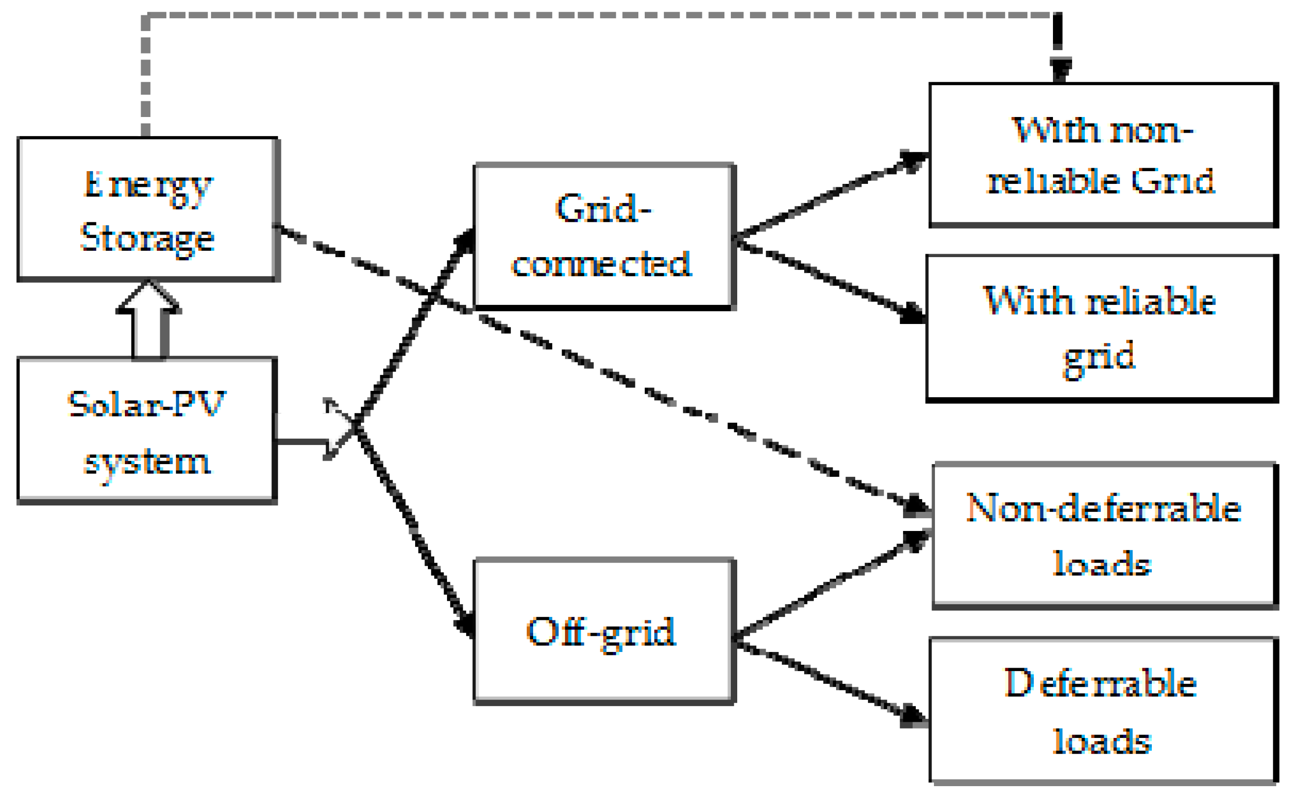
Generally, as shown in Figure 1, two major layouts comprise a solar-PV system according to many factors, such as the operation and control capabilities, and operating mode. The first layout is the grid-connected solar-PV system, whereas the second layout is the off-grid solar-PV system. The selection of the appropriate layout of the system has a significant impact on reliability.
The grid-connected solar-PV system is ideally located close to the grid, which is directly fed by its output power. In the case of the power balance, the constraint for supplying the local load is secured by the grid, there is no need for storage devices with grid-connected solar-PV systems. This is due to the sufficient reliability of the grid for supplying these local loads. Therefore, the grid-connected solar-PV systems are classified into either grids with insufficiently low reliability or grids with sufficiently high reliability, based on the grid reliability level.
Furthermore, based on the techno-economic impacts of interrupting a specific load; power system loads can be classified into three categories; non-essential, essential, and critical loads. Long power interruptions are acceptable in the case of non-essential loads, while very short power interruptions are allowed in the case of essential loads. The critical loads should be interrupted even for very short durations. Consequently, in grid-connected solar-PV, where the grid reliability is insufficient, the energy storage is required for supplying essential and critical loads in the case of the grid outage [15,16,17,18,19]. The overall system, then acts as the uninterruptable power supply (UPS).
On the other hand, for remote where electricity is difficult to obtain from traditional sources (utility grid), the off-grid solar-PV systems are the best choice to cover these distinct situations. In this case, the load instantaneous power balance constraint plays a very important role in the presence of the energy storage system or not. Accordingly, there are two main types of loads; the first type is the non-deferrable loads, which required instantaneous power balance for their proper operation. Therefore, energy storage is required in off-grid solar-PV systems that fed non-deferrable loads. The second load type is deferrable loads which refer to a load type at which its energy requirements can be postponed to another nearby time. The energy storage is not preferred with the off-grid solar-PV systems that fed deferrable loads. The common example of deferrable loads is a water irrigation pumping systems [1]. Generally, the off-grid systems, supplying deferrable loads, do not require electric energy storage; however, storage tanks may be used to use the surplus power for water storage in irrigation water pump systems.
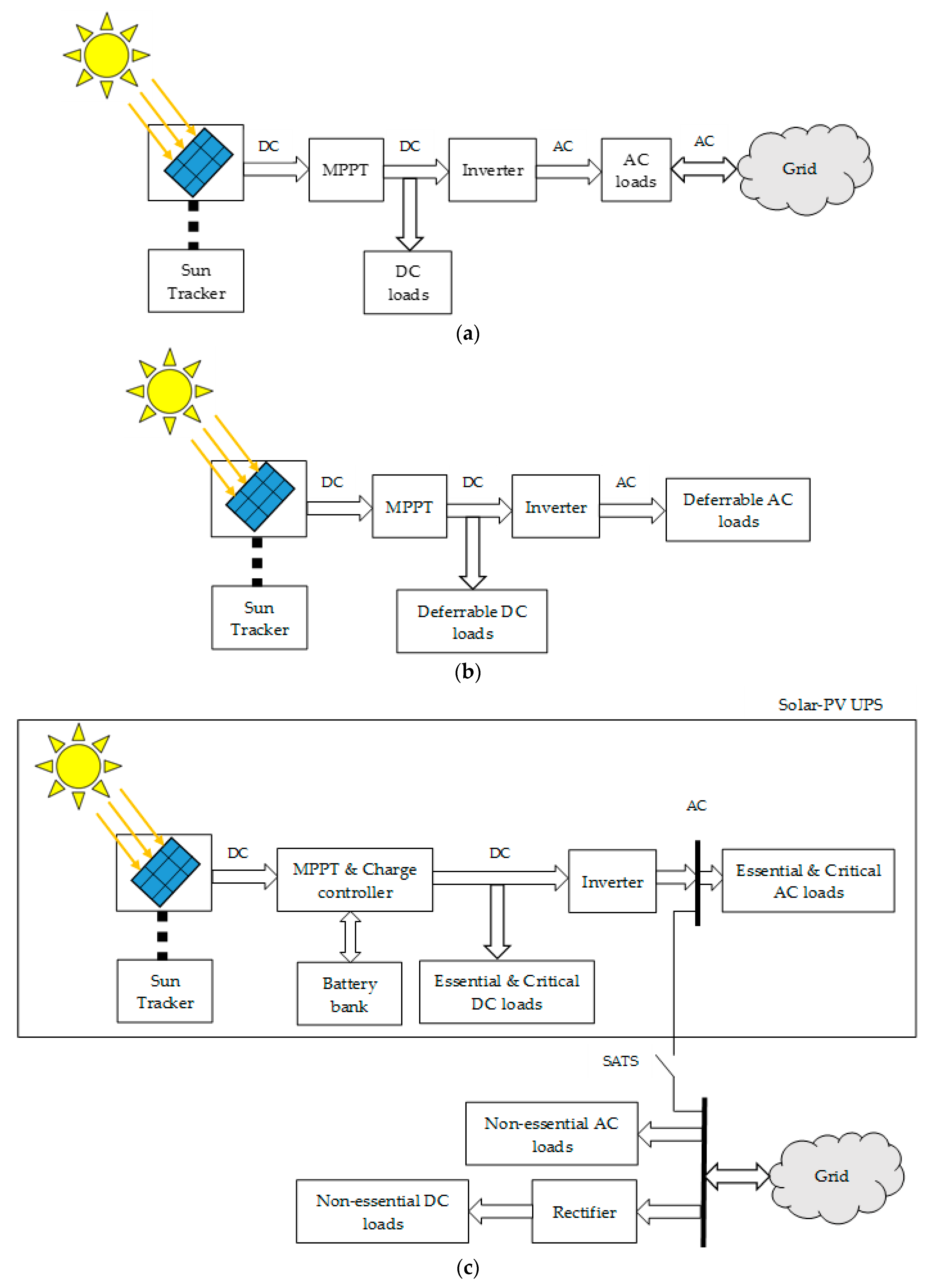
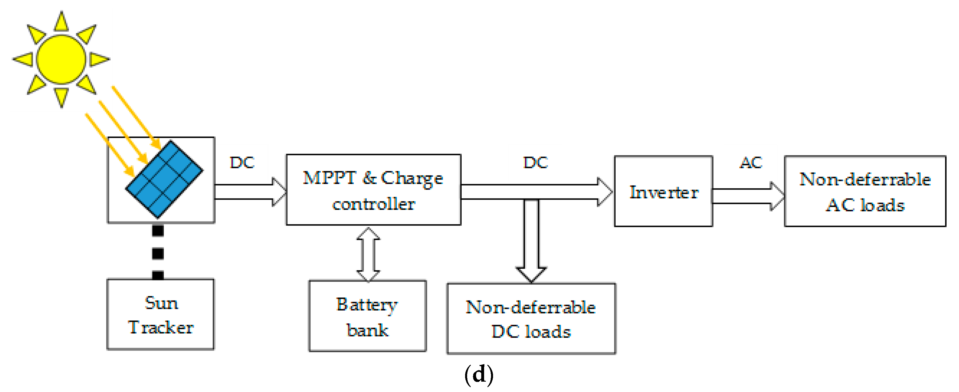
Based on previous discussions about the various layouts of the solar-PV systems, Figure 2 demonstrates these layouts. The DC-DC converter acts as a charge controller in layouts without battery storage, whereas it acts also as maximum power point tracker (MPPT) in layouts with battery storage. The automatic static transfer switch (ASTS) is used in grid-connected systems that are connected to a low reliability grid for securing immediate proper islanding of the solar-PV system through its sensing, and switching control logics. In the island mode, the grid is disconnected due to either, an outage, or a sever power quality problem. In this case, the non-essential load is isolated from the solar-PV system, while the energy required by the essential and critical loads is produced from the solar-PV. The power balance is the island mode is secured by the battery energy storage. This paper will focus only on the large scale grid-connected solar-PV system with grid has low reliability.

3. Reliability Analysis

3.1. General Reliability Concepts and Functions

Generally, reliability is defined as the probability of system, subsystem, or even sub-assemblies to perform its required function adequately. The reliability function of a system is the probability of successfully operating the system within a given time, t. The reliability or survivor function equation for a system can be written as:
R(T) = P(T > t).
The cumulative distribution function (CDF), denoted F(t), is called failure probability or unreliability. It interprets the probability of the system’s success, which can be given by:
F ( t ) = 1 R ( t ) = P ( T t ) .
The probability density function (PDF), denoted f(t), indicates the distribution of the failure over the entire time range. Equations (1) and (2) can be expressed with the density function f(t) as:
R ( t ) = t f ( t ) d t .
F ( t ) = t f ( t ) d t .
The mean time to failure (MTTF) for the sub-assembly, which expresses the expected life for the sub-assembly, represents the most common method for specifying reliability of non-repairable items. It can be calculated by:
M T T F = 0 t × f ( t ) d t = 0 R ( t ) d t .
The solar-PV systems are complex and contain a large number of sub-assemblies that may be connected in series, in parallel or even a combination of series and parallel. When the sub-assemblies connected in series, the overall system will be interrupted in case of failure of one sub-assembly. On the other hand, all subassemblies must fail in order to interrupt the overall system in the parallel system.
According to Boolean techniques, the reliability performance for a non-repairable system contains an independent series n subassemblies can be calculated by:
R S y s t e m = i = 1 n R i ,
where, Ri is the reliability of the sub-assembly i.
For an exponential distribution, the total sub-assembly reliability becomes:
R S u b A s s e m b l y , T o t = exp ( i = 1 n m i λ i t ) ,
where, mi is the total number of the sub-assembly i, and λi is the failure rate of sub-assembly i.
If the system contains x series units with M parallel subassemblies, the system reliability can be obtained using:
R S y s t e m = 1 ( 1 R x ) M .

3.2. System Decomposition

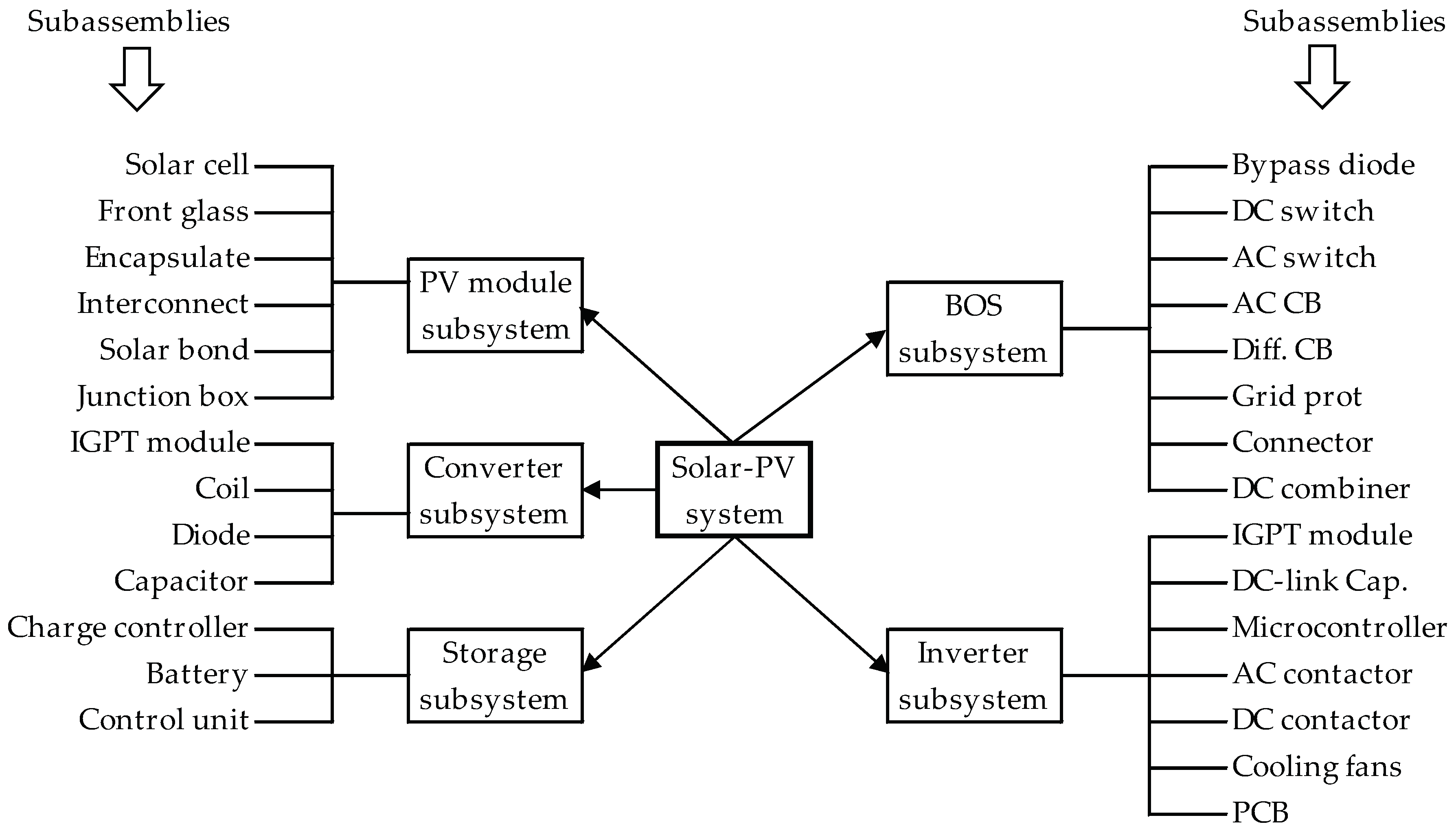
System Decomposition represents the first stage in RMA analysis. Here, the main system is decomposed into subsystems according to their functions. The subsystem may also be divided into sub-assemblies. However, many studies have been focused on the major components in large scale solar-PV systems or analyzed on only one subsystem in the reliability study. This is due to the lower availability of data for all sub-assemblies of the large scale solar-PV systems, as mentioned previously, or to overcome the complicity that arises from connecting more than one subsystem. Generally, the main solar-PV system is decomposed into five subsystems according to their functions; PV module, DC-DC converter, inverter, BOS, and battery storage subsystems. Furthermore, each of these subsystems is divided into sub-assemblies, as demonstrated in Figure 3.
The BOS subsystem consists of all the non-modular sub-assemblies of the solar-PV power plants, as illustrated in Figure 3. The failure of the BOS subsystem represents one of the major reasons for interrupting the power produced on PV field. Sandia National Laboratories found that the failure of the BOS components was responsible for 54% of the non-producing modules, around 10,000 non-working modules of 35 PV systems [20]. In the literature, studies which focus on BOS reliability evaluation are limited and the most of publications consider the reliability of the PV module. A fault tree method, based on qualitative reliability analysis, is introduced in [13]. The lifetime, reliability, and availability estimation of both PV modules and BOS are presented in [21] using Petri’s networks.
The layout of the PV system varies according to architectural design. It can be a single-inverter system, a string-inverter system or a multi-inverter system. A single-inverter system is used when all the strings are connected to a central inverter. A string-inverter system is used when each string has its own inverter. A multi-inverter system is used when the PV field is divided into groups of strings connected to an inverter.
Generally, a typical three-phase PV inverter includes insulated-gate bipolar transistor (IGBT) Power modules, cooling fans, control software, and DC link capacitors implemented on printed circuit boards (PCBs) in addition to AC and DC contactors. In order to obtain layouts simplification, these sub-assemblies were not considered in the PV inverter, and the reliability data is collected for the whole inverter regardless of the layout type (single-inverter system or a string-inverter system or a multi-inverter system). Although, these layouts have a significant impact on the reliability assessment, the proposed simplification ensures the collection of more than one option and obtaining more accurate results.
In the PV module, solar cells are connected together in a series and the number of cells is usually governed by the specified voltage of the module. The typical number of the series cells in the PV module is 36 cells, but some modules exist with 48 cells. The PV module subsystem consists of various sub-assemblies as shown in Figure 3. Due to the limited reliability data of these sub-assemblies, this study deals with the subsystem as a whole. This means that the reliability data is considered for the entire PV module subsystem.
The encapsulation of the PV module subjected to three main failures well known as Discoloration and Delamination (D and D), moisture ingress, and module broken glass. In order to obtain a clear view of the reliability of the PV module, the PV module failure rate data only without the encapsulate failures was collected. A complete reliability analysis of failures of a PV module encapsulation, using a Markov process is presented in [9].

3.3. Reliability Modelling

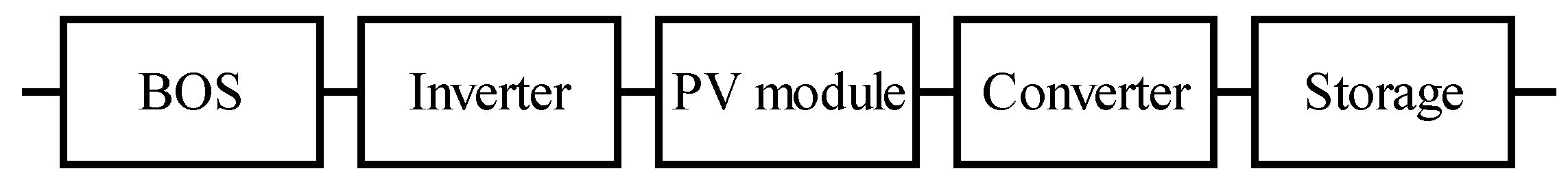
Reliability modelling represents the second stage in RAM analysis. Several methods of reliability have been discussed in recent times for RMA evaluations. One of these most powerful methods in modeling the grid-connected solar-PV system is RBD. In RBD, the system components are interpreted by either, sequential or parallel blocks, which link with each other depending on their effects on the whole system. Each block of each component is described by the failure and repair rates of this component. As discussed previously, the grid-connected solar-PV system comprises five clearly identifiable subsystems for the purposes of RAM analysis. All of these subsystems are functionally arranged in a series configuration, as shown in the simplified reliability block diagram in Figure 4. This means that the grid-connected solar-PV system is in working condition only when all subsystems are working satisfactorily. The failure rate and repair rate of this system, as a whole, can be calculated by Equations (9) and (10).
λ T o t = i = 1 n λ i .
μ T o t = i = 1 n λ i / i = 1 n λ i μ i .

3.4. Failure and Repair Rates for Various Sub-Assemblies of solar-PV Systems

Obtaining accurate failure and repair rates represents an important stage in RAM analysis. It is represented as the main challenge in this analysis. Therefore, the largest amounts of reliability data, failure and repair rates, are collected from the literature. Various technologies and layouts are considered in the obtained data. In addition, the collected data are characterized by different scan times. The median values of the sorted data of each sub-assembly is then calculated. It is noted that the use of the median values, instead of the average values, statistically decreases the uncertainties of the collected data per sub-assembly. Table 1 summarizes the collected data, failure, and repair rates for each sub-assembly of the generic solar-PV system.
In order to evaluate the RAM results of each sub-assembly, seven large scale grid connected solar-PV systems, were designed. The nominal power of these systems ranged from 100 kW to 2500 kW. Of course, the total number of sub-assemblies increased with the PV system intended power output. The resulting number of sub-assemblies for each system is listed in Table 2. More details of some sub-assemblies are presented in Appendix A. The method which used to design/select each sub-assembly is presented in Appendix B. Based on the data given in Table 1 and Table 2 and the RBD method, the failure and repair rates of each sub-assembly of the seven studied solar-PV systems are listed in Table 3, and Table 4, respectively.

4. RAM Results for Solar-PV System

In this section, we will analyze the RMA results for the seven solar-PV systems, with an average of 8.5 hours operations a day. These 8.5 hours is the average sunshine hours. Of course, the batteries will have an operating time greater than the operating hours of the PV modules, according to the number of hours needed during the periods of no sunshine. Substituting the failure rates listed in Table 3 into Equation (7) yields the results summarized in Table 5 and Table 6 for one, and twenty years of operations, respectively.
The reliability of the sub-assembly decreased as the PV power output increased; for instance, after one year for a 100 kW system, the PV module had a 97.9603% probability of operating without failure, while the inverter only had a 88.2497% probability. For a 1.5 MW system, the PV module had a 73.5409% probability of operating without failure, while the inverter had only a 17.3775% probability (see Table 5). However, for 20 years of operation, the quick decline in reliability is noted. For a 100 kW system, the PV module was 66.2218% reliable, while the inverter subsystem was only 8.20855% reliable. For a 1.5 MW system, the PV module had only a 0.21408% probability of operating correctly, while the inverter subsystem was not reliable, with a 0% probability of operating without failure (see Table 6).
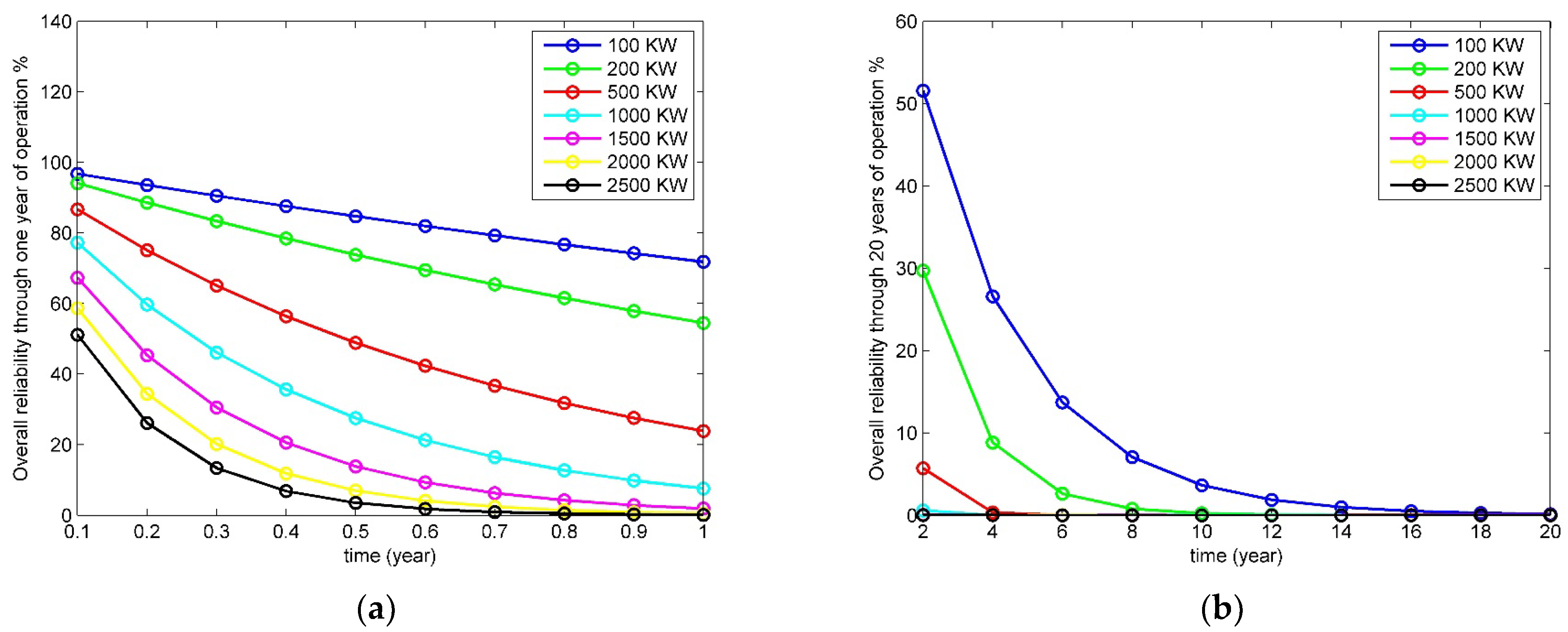
Zero% reliability means that at least one subsystem of the PV system is failing, it does not mean that the overall PV system is failed. The overall system reliability through one year and 20 years of operation is illustrated in Figure 5.
The total component availability of PV systems was estimated (See Table 7) using Equation (11). As shown in Table 7 that, the availability of the sub-assembly decreased as the PV power output increased.
A i = μ i λ i + μ i .
It is also clear from Table 7 that the storage system has a higher availability among the all sub-assemblies. Whereas, the inverter subsystem records the lower availability among the five subsystems.
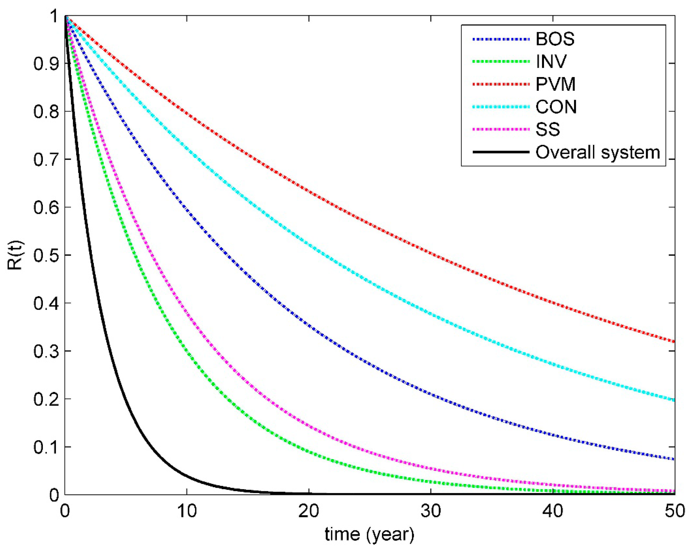
From a reliability point of view, the reliability of the system is the probability of success of that system to perform its required function without any failures, under certain conditions and for a stated period of time. Hence, the reliability of each subsystem, and the reliability of the total solar-PV system, are presented in Figure 6. Based on Figure 6, the MTTF of each subsystem was calculated and listed in Table 8. As shown in Figure 6, the reliability of the PV array subsystem is 0.7956 and 0.5036 after 10, and 30 years, respectively. Meanwhile, the calculated Mean time to repair (MTTR) is 43.73 years. This is due to the aging characteristics of the PV module, which carries the same aging characteristics of semi-conductors when the PV module failure rates did not include the encapsulate failures. These reduce the lifetime of PV modules to the current values declared by manufacturers.
Some studies consider the PV inverter (INV) to be just a sub-assembly among other BOS sub-assemblies [33]. Whereas the main concern of the current studies is quite limited to reliability estimations of INV and reliability improvements of current INV [34,35,36,37,38]. Thus, this study separates the BOS subsystem and the INV subsystem. The reliability of the INV subsystem is 0.7858, and 0.2996 after 2, and 10 years, respectively. While the reliability of the BOS subsystem is 0.5942, and 0.2098 after 10, and 30 years, respectively. By applying (5), the MTTF of PVI, and BOS subsystems are 8.3, and 19.21 years, respectively. The main reasons behind the lower MTTF of the INV subsystem is mainly due to either, the complexity of the inverter, or because the inverter contains electronic components, which significantly affected by various stress factors. Therefore, the lifetime of the INV in the solar-PV systems is very low compared with the predicted average lifetime of the solar-PV system, which is in the range 20–25 years.

5. Best PDFs for Various Sub-Assemblies of Solar-PV Systems

The choice of probability distribution models represent an important part in selecting the best-fit probability distribution for a certain failure rates. In this section, the selected distribution models, which are commonly used in extreme failure analyses, are presented. The method for the best distribution models, and the goodness of fit tests for model selection, are presented.
The commonly used frequency distributions, discussed in previous studies, are adopted in this analysis. Previously, the parameters of these distributions have been estimated by the method of moments (MOM) and L-moments estimators. In this paper, the statistics toolbox in the MATLAB will be used to estimate these parameters for the most commonly used frequency distributions, such as Weibull PDF, Exponential PDF, and Log-normal PDF using the data shown in Table 1. According to MOM; arithmetic values of the sample mean X, standard deviation σ, and Variance V are calculated for these data. A comparison was utilized between the arithmetic values and the obtained data of the selected distributions, in order to identify the best-fit distribution between the selected distributions. The minimum deviation of the three values. X, σ, and V from the arithmetic values will provide the best-fit distribution. The results show that the best PDF for some subassemblies, such as PV module, connector, and charge controller is exponential PDF. Whereas the best PDF for the sub-assemblies, such as DC-DC converter, bypass diode, AC switch, AC CB, and differential CB is Weibull PDF. The best PDF for the rest of the subassemblies is lognormal PDF as illustrated in Table 9.
A comparison between the proposed RAM analysis, using RBD method, and other reliability analysis, using FTA methods has been implemented in Table 10. As shown in Table 10, the proposed RAM analysis introduces a detailed analysis of reliability, maintainability, and availability. Whereas, the other methods give only the reliability analysis of the failure information only. Moreover, the proposed RAM analysis introduces the best PDFs for all sub-assemblies, as well as the expected lifetime of each subsystem. Table 11 introduces a comparison between the reliability results when applying RAM analysis, using RBD method in the proposed technique, and the FTA method discussed in [13] and [22].

6. Conclusions

The RAM analysis of seven practical layouts of the grid-connected solar-PV conversion systems are studied in detail, and a novel approach was conducted in order to estimate the best probability density function (PDF) for the failure rate of each sub-assembly of these systems. The results show that the best PDF for some sub-assemblies, such as PV module, connector, and charge controller is exponential PDF. Whereas the best PDF for the sub-assemblies, such as DC-DC converter, bypass diode, AC switch, AC CB, and differential CB is Weibull PDF. The best PDF for the rest of the subassemblies of the solar-PV system is lognormal PDF. In reliability analysis, the expected lifetime of the PV modules without the encapsulation failures records 43.73 years. Whereas the expected lifetime of the converter, BOS, inverter, and storage system are 30.77, 19.21, 8.3, and 10.31 years respectively.

Author Contributions

Sayed did the literature review; A.S. and M.E. constructed the simulation models; M.E. and M.E.-S. revised the models and proposed tested cases and results formulation; A.S. and M.E. did the data analysis for this paper; A.S., M.E. and M.E.-S. have contributed to writing the paper; M.E., M.E.-S. and M.E.-M. reviewed and edited the manuscript; M.E.-M. as a main supervisor followed up all study steps and gave helpful advice; All authors discussed the results, read and approved the manuscript; A.S. and M.E. prepared the revised versions and replies to the comments of reviewers until the final acceptance of manuscript.

Funding

This research received no external funding.

Conflicts of Interest

The authors declare no conflict of interest.

Nomenclature

RAMReliability, availability, and maintainability
RBDReliability block diagram
PDFProbability density function
PVMPV module
BOSbalance of systems
FTAfault tree analysis
UPSuninterruptable power supply
MPPTmaximum power point tracker
ASTSautomatic static transfer switch
R(t)reliability function
CDFCumulative distribution function
MTTFMean time to fail
MTTRMean time to repair
λfailure rate
µrepair rate
PCBsprinted circuit boards
D&Ddiscoloration and delamination
CONDC-DC converter
INVinverter subsystem
SSstorage subsystem
XArithmetic mean
σStandard deviation
VVariance

Appendix A

Data for PV module (230 W):
Short circuit current of module = 8.24 A, open circuit voltage of module = 37.2 V, Module current at MPP = 7.60 A, Module voltage at MPP = 30.2 V.
Data for Inverter (100 KW):
Maximum DC current of the inverter = 235 A, the maximum voltage of the inverter = 1000 V, the minimum voltage of the inverter at MPP = 450 V, and the maximum voltage of the inverter at MPP = 820 V.
Data for batteries:
The batteries used in this study came from the Rolls-Surrette factory. All PV systems used an identical battery model, Ah and voltage, 12 CS 11P, 475 Ah and 12 V, respectively.
Data for DC-DC boost converter:
D = 0.531 − 0.493, L = 8.31 mH, C = 255 µf, and Fs=10 KHz.

Appendix B

The following Table gives a method used to design/selected each sub-assembly in large scale grid-connected solar-PV system. As an example, we will describe that for a 200 kW PV system.
Table A1. Method of design/selected each sub-assembly.
Sub-assemblyDescriptionFormulaResults
PV modules1- Determining the total load power, P, kW.P=P1 + P2 +…+ Pn
2- Determining the operating time per day for each load.(T1, T2, …, Tn)
3- Calculating the total energy per day.E= P1 × T1 + P2*T2 +…+ Pn × Tn532544.4 WHr
4- Calculating the total energy per day needed from the PV array.=1.3 × Total Energy692307.7 WHr
5- Determining the panel generation factor, PGA.here in this paper by assumptions3.45 kWh/kWp/day
6- Calculating the total Watt-peak rating of the PV array.= total energy per day needed from the PV array/PGF.200668.9 W
7- Calculating the number of modules.= total Watt-peak rating of the PV array/rated power of the selected PV module≈874
Bypass diodeCalculating the number of bypass diode= Number of modules/number of arrays= 874/19 = 46
InverterCalculating the number of inverters= Rated power of the system/rated power of the selected inverter2
AC CBCalculating the number of the AC circuit breakerAccording to the numbers of the inverters2
AC SwitchCalculating the number of the AC switchAccording to grid requirements1
Differential CBCalculating the number of the differential circuit breakerAccording to grid requirements1
Grid ProtectionCalculating the number of the grid protectionAccording to grid requirements1
connector (coupler)Calculating the number of the connectors= Number of modules × 21748
BatteriesCalculating the number of the batteries in the battery bank.= (200 kW × 2 days × 8.5 Hr × 5%)/12 V/475 AHr30

References

  1. Balcioglu, H.; Soyer, K.; EL-Shimy, M. Techno-Economic Modeling and Analysis of Renewable Energy Projects. In Economics of Variable Renewable Sources for Electric Power Production; Lambert Academic Publishing/Omniscriptum Gmbh & Company Kg: Saarbrücken, Germany, 2017; pp. 35–61. ISBN 978-3-330-08361-5. [Google Scholar]
  2. Baschel, S.; Koubli, E.; Roy, J.; Gottschalg, R. Impact of Component Reliability on Large Scale Photovoltaic Systems’ Performance. Energies 2018, 11, 1579. [Google Scholar] [CrossRef]
  3. Al-Rawi, N.A.; Al-Kaisi, M.M.; Asfer, D. Reliability of photovoltaic modules I. Theoretical considerations. Sol. Energy Mater. Sol. Cells 1994, 31, 455–468. [Google Scholar] [CrossRef]
  4. Alonso, R.; Roman, E.; Sanz, A.; Santos, V.E.M.; Ibanez, P. Analysis of Inverter-Voltage Influence on Distributed MPPT Architecture Performance. IEEE Trans. Ind. Electron. 2012, 59, 3900–3907. [Google Scholar] [CrossRef]
  5. Wohlgemuth, J.H.; Cunningham, D.W.; Monus, P.; Miller, J.; Nguyen, A. Long Term Reliability of Photovoltaic Modules. In Proceedings of the 2006 IEEE 4th World Conference on Photovoltaic Energy Conference, Waikoloa, HI, USA, 7–12 May 2006; Volume 2, pp. 2050–2053. [Google Scholar]
  6. Dhere, N.G.; Shiradkar, N.; Schneller, E.; Gade, V. The reliability of bypass diodes in PV modules. Proc. SPIE 2013, 8825. [Google Scholar] [CrossRef]
  7. Review of Failures of Photovoltaic Modules Final. Available online: https://www.researchgate.net/publication/274717701 (accessed on 1 January 2019).
  8. Wu, D.; Zhu, J.; Betts, T.R.; Gottschalg, R. Degradation of interfacial adhesion strength within photovoltaic mini-modules during damp-heat exposure. Prog. Photovolt. Res. Appl. 2014, 22, 796–809. [Google Scholar] [CrossRef] [Green Version]
  9. Cristaldi, L.; Khalil, M.; Faifer, M.; Soulatiantork, P. Markov process reliability model for photovoltaic module encapsulation failures. In Proceedings of the 2015 International Conference on Renewable Energy Research and Applications (ICRERA), Palermo, Italy, 22–25 November 2015; pp. 203–208. [Google Scholar]
  10. Zhang, P.; Li, W.; Li, S.; Wang, Y.; Xiao, W. Reliability assessment of photovoltaic power systems: Review of current status and future perspectives. Appl. Energy 2013, 104, 822–833. [Google Scholar] [CrossRef]
  11. Hamdy, M.A.; Beshir, M.E.; Elmasry, S.E. Reliability analysis of photovoltaic systems. Appl. Energy 1989, 33, 253–263. [Google Scholar] [CrossRef]
  12. Hu, R.; Mi, J.; Hu, T.; Fu, M.; Yang, P. Reliability research for PV system using BDD-based fault tree analysis. In Proceedings of the 2013 International Conference on Quality, Reliability, Risk, Maintenance, and Safety Engineering (QR2MSE), Chengdu, China, 15–18 July 2013; pp. 359–363. [Google Scholar]
  13. Zini, G.; Mangeant, C.; Merten, J. Reliability of large-scale grid-connected photovoltaic systems. Renew. Energy 2011, 36, 2334–2340. [Google Scholar] [CrossRef]
  14. Chiacchio, F.; Famoso, F.; D’Urso, D.; Brusca, S.; Aizpurua, J.I.; Cedola, L. Dynamic performance evaluation of photovoltaic power plant by stochastic hybrid fault tree automaton model. Energies 2018, 11, 306. [Google Scholar] [CrossRef]
  15. Kaundinya, D.P.; Balachandra, P.; Ravindranath, N.H. Grid-connected versus stand-alone energy systems for decentralized power—A review of literature. Renew. Sustain. Energy Rev. 2009, 13, 2041–2050. [Google Scholar] [CrossRef]
  16. Siyambalapitiya, D.J.T.; Rajapakse, S.T.K.; de Mel, S.J.S.; Fernando, S.I.T.; Perera, B.L.P.P. Evaluation of grid connected rural electrification projects in developing countries. IEEE Trans. Power Syst. 1991, 6, 332–338. [Google Scholar] [CrossRef]
  17. Sidrach-de-Cardona, M.; López, L.M. Evaluation of a grid-connected photovoltaic system in southern Spain. Renew. Energy 1998, 15, 527–530. [Google Scholar] [CrossRef]
  18. Atikol, U.; Güven, H. Impact of cogeneration on integrated resource planning of Turkey. Energy 2003, 28, 1259–1277. [Google Scholar] [CrossRef]
  19. Fernández-Infantes, A.; Contreras, J.; Bernal-Agustín, J.L. Design of grid connected PV systems considering electrical, economical and environmental aspects: A practical case. Renew. Energy 2006, 31, 2042–2062. [Google Scholar] [CrossRef]
  20. Rosenthal, A.L.; Thomas, M.G.; Durand, S.J. A ten year review of performance of photovoltaic systems. In Proceedings of the Conference Record of the Twenty Third IEEE Photovoltaic Specialists Conference-1993 (Cat. No.93CH3283-9), Louisville, KY, USA, 10–14 May 1993; pp. 1289–1291. [Google Scholar]
  21. Theristis, M.; Papazoglou, I.A. Markovian Reliability Analysis of Standalone Photovoltaic Systems Incorporating Repairs. IEEE J. Photovolt. 2014, 4, 414–422. [Google Scholar] [CrossRef]
  22. Ahadi, A.; Ghadimi, N.; Mirabbasi, D. Reliability assessment for components of large scale photovoltaic systems. J. Power Sources 2014, 264, 211–219. [Google Scholar] [CrossRef]
  23. Perdue, M.; Gottschalg, R. Energy yields of small grid connected photovoltaic system: Effects of component reliability and maintenance. IET Renew. Power Gener. 2015, 9, 432–437. [Google Scholar] [CrossRef]
  24. Gupta, N.; Garg, R.; Kumar, P. Sensitivity and reliability models of a PV system connected to grid. Renew. Sustain. Energy Rev. 2017, 69, 188–196. [Google Scholar] [CrossRef]
  25. Charki, A.; Bigaud, D. Availability Estimation of a Photovoltaic System. In Proceedings of the 2013 Annual Reliability and Maintainability Symposium (RAMS), Orlando, FL, USA, 28–31 January 2013; pp. 1–5. [Google Scholar]
  26. Cai, B.; Liu, Y.; Ma, Y.; Huang, L.; Liu, Z. A framework for the reliability evaluation of grid-connected photovoltaic systems in the presence of intermittent faults. Energy 2015, 93, 1308–1320. [Google Scholar] [CrossRef]
  27. Ahadi, A.; Hayati, H.; Miryousefi Aval, S.M. Reliability evaluation of future photovoltaic systems with smart operation strategy. Front. Energy 2016, 10, 125–135. [Google Scholar] [CrossRef]
  28. Sulaeman, S.; Benidris, M.; Mitra, J. Modeling the output power of PV farms for power system adequacy assessment. In Proceedings of the 2015 North American Power Symposium (NAPS), Charlotte, NC, USA, 4–6 October 2015; pp. 1–6. [Google Scholar]
  29. Nemes, C.; Munteanu, F.; Rotariu, M.; Astanei, D. Availability assessment for grid-connected photovoltaic systems with energy storage. In Proceedings of the 2016 International Conference and Exposition on Electrical and Power Engineering (EPE), Iasi, Romania, 20–22 October 2016; pp. 908–911. [Google Scholar]
  30. Colli, A. Failure mode and effect analysis for photovoltaic systems. Renew. Sustain. Energy Rev. 2015, 50, 804–809. [Google Scholar] [CrossRef]
  31. Ghaedi, A.; Abbaspour, A.; Fotuhi-Firuzabad, M.; Moeini-Aghtaie, M.; Othman, M. Reliability evaluation of a composite power system containing wind and solar generation. In Proceedings of the 2013 IEEE 7th International Power Engineering and Optimization Conference (PEOCO), Langkawi, Malaysia, 3–4 June 2013; pp. 483–488. [Google Scholar]
  32. Walls, L.; Revie, M.; Bedford, T. Risk, Reliability and Safety: Innovating Theory and Practice, Eds; Taylor & Francis: London, UK, 2017; ISBN 978-1-138-02997-2. [Google Scholar]
  33. Cristaldi, L.; Khalil, M.; Soulatiantork, P. A root cause analysis and a risk evaluation of PV balance of system failures. Acta Imeko 2017, 6, 113–120. [Google Scholar] [CrossRef]
  34. Harb, S.; Balog, R.S. Reliability of Candidate Photovoltaic Module-Integrated-Inverter (PV-MII) Topologies—A Usage Model Approach. IEEE Transactions on Power Electronics 2013, 28, 3019–3027. [Google Scholar] [CrossRef]
  35. Pregelj, A.; Begovic, M.; Rohatgi, A. Impact of inverter configuration on PV system reliability and energy production. In Proceedings of the Conference Record of the Twenty-Ninth IEEE Photovoltaic Specialists Conference, New Orleans, LA, USA, 19–24 May 2002; pp. 1388–1391. [Google Scholar]
  36. Fife, J.M.; Scharf, M.; Hummel, S.G.; Morris, R.W. Field reliability analysis methods for photovoltaic inverters. In Proceedings of the 2010 35th IEEE Photovoltaic Specialists Conference, Honolulu, HI, USA, 20–25 June 2010; pp. 2767–2772. [Google Scholar]
  37. Battistelli, L.; Chiodo, E.; Lauria, D. Bayes assessment of photovoltaic inverter system reliability and availability. In Proceedings of the SPEEDAM 2010, Pisa, Italy, 14–16 June 2010; pp. 628–634. [Google Scholar]
  38. Ma, Z.J.; Thomas, S. Reliability and maintainability in photovoltaic inverter design. In Proceedings of the 2011 Proceedings—Annual Reliability and Maintainability Symposium, Lake Buena Vista, FL, USA, 24–27 January 2011; pp. 1–5. [Google Scholar]
Figure 1. Energy storage requirements for various layouts of solar-photovoltaic (PV) systems.
Energies 12 01213 g001
Figure 2. Various layouts of solar-PV systems: (a) grid-connected solar PV system with reliable grid; (b) off-grid PV systems with deferrable loads; (c) grid-connected solar PV system with low reliability grid; (d) off-grid PV systems with non-deferrable loads.
Energies 12 01213 g002aEnergies 12 01213 g002b
Figure 3. System decomposition of a generic solar-PV system.
Energies 12 01213 g003
Figure 4. Simple reliability block diagram of grid-connected solar-PV system.
Energies 12 01213 g004
Figure 5. Impact of operational failure of various solar PV systems (a) for a period of one year of operations and (b) for a period of 20 years of operations
Energies 12 01213 g005
Figure 6. Reliability of subsystem and overall solar-PV system.
Energies 12 01213 g006
Table 1. Failure and repair rates for various subassemblies of solar-PV systems [9,21,22,23,24,25,26,27,28,29,30,31,32].
Sub-assemblyFailure Rate, λ,
(10−6 Failures yr−1)
Repair Rate, μ,
(yr-1)
References
PV modules26NA[24]
3.20.0667[26]
4.60.0057[21]
0.0150.0037[9,22,23,27]
0.0150.0037[29]
1.4NA 1[25]
0.00460.025[30]
240.0039[31]
NA0.0083[32]
Converter5.9NA[24]
8.10.13[26]
270.1[28]
0.460.025[31]
Bypass diode5.40.1667[26]
0.310.0208[9,22,23,27]
0.310.0208[29]
3.5NA[25]
0.68NA[30]
0.310.0208[32]
DC switch0.20.0208[9,22,23,27]
0.20.0207[29]
0.7NA[30]
0.20.0208[32]
AC Switch0.0340.0208[9,22,23,27]
0.0340.0207[29]
0.7NA[30]
0.0340.0208[32]
AC circuit breaker5.70.0208[9,22,23,27]
5.70.0207[29]
0.4NA[30]
5.70.0208[32]
Differential circuit breaker5.70.0208[9,22,23,27]
5.70.0207[29]
0.23NA[30]
5.70.0208[32]
Grid Protection5.70.0208[9,22,23,27]
5.60.0207[29]
5.70.0208[32]
connector (coupler)0.000240.00148[9,22,23,27]
0.00020.0016[29]
0.45NA 1[30]
0.00020.0015[32]
Inverter20NA[24]
130.0833[26]
110.0057[21]
400.00208[9,22,23,27]
270.1[28]
400.0021[29]
7.60.0025[25]
180NA[30]
570.0057[31]
NA0.0021[32]
Charge controller44NA[24]
14NA[21]
6.40.01612[9,22,23,27]
6.40.0006[29]
Battery system19NA[24]
110.0057[26]
130.006[29]
1 Not available.
Table 2. Number of sub-assembly for each PV system [22].
Power (KW)1002005001000150020002500
PV modules437874216643516517870210868
Converter361527425772
Bypass diode2346114229343458572
DC switch361527425772
AC Switch1111111
AC circuit breaker1259141924
Differential circuit breaker1111111
Grid Protection1111111
connector (coupler)874174843328702130341740421736
Inverter1259141924
Charge controller1111111
Battery system163076150224298372
Table 3. Sub-assembly failure rate (yr-1).
Power (KW)1002005001000150020002500
PV modules0.020610.041220.102140.205180.307330.410370.51251
Converter0.08750.1750.43750.78751.2251.66252.1
Bypass diode0.022330.044670.11070.222380.333080.444760.55546
DC switch0.001860.003720.009310.016750.026060.035370.04468
AC Switch0.000110.000110.000110.000110.000110.000110.00011
AC circuit breaker0.017720.035440.088610.159490.24810.336710.42532
Differential circuit breaker0.017720.017720.017720.017720.017720.017720.01772
Grid Protection0.017720.017720.017720.017720.017720.017720.01772
connector (coupler)0.000650.00130.003230.006480.009710.012960.01618
Inverter0.1250.250.6251.1251.752.374992.99999
Charge controller0.019980.019980.019980.019980.019980.019980.01998
Battery system4 × 10−68 × 10−61.9 × 10−53.8 × 10−55.8 × 10−57.7 × 10−59.6 × 10−5
Table 4. Sub-assembly repair rate (yr-1).
Power (KW)1002005001000150020002500
PV modules11.696411.696411.696411.696411.696411.696411.6964
Converter387.813387.813387.813387.813387.813387.813387.813
Bypass diode64.53264.53264.53264.53264.53264.53264.532
DC switch64.53264.53264.53264.53264.53264.53264.532
AC Switch64.53264.53264.53264.53264.53264.53264.532
AC circuit breaker64.53264.53264.53264.53264.53264.53264.532
Differential circuit breaker64.53264.53264.53264.53264.53264.53264.532
Grid Protection64.53264.53264.53264.53264.53264.53264.532
connector (coupler)4.582924.582924.582924.582924.582924.582924.58292
Inverter12.654712.654712.654712.654712.654712.654712.6547
Charge controller50505050505050
Battery system144.5270.938686.3751354.6920232691.313359.63
Table 5. Subassemblies reliability for the PV systems for a period of one year of operations (in %).
Power (KW)1002005001000150020002500
PV modules97.960395.962290.289981.449773.540966.340559.8988
Converter91.621983.945764.564945.498229.375818.966512.2457
Bypass diode97.791395.631389.520480.061371.671264.098157.3809
DC switch99.81499.628499.073698.338697.427696.52595.6307
AC Switch99.989599.989599.989599.989599.989599.989599.9895
AC circuit breaker98.243596.517891.520585.257678.028171.411765.3564
Differential circuit breaker98.243598.243598.243598.243598.243598.243598.2435
Grid Protection98.243598.243598.243598.243598.243598.243598.2435
connector (coupler)99.934999.869999.67899.354199.034298.712598.3946
Inverter88.249777.880153.526232.465317.37759.30154.97874
Charge controller98.021898.021898.021898.021898.021898.021898.0218
Battery system99.999699.999299.998199.996299.994299.992399.9904
Table 6. Subassemblies reliability for the PV systems for a period of 20 years of operations [in %].
Power (KW)1002005001000150020002500
PV modules66.221843.853212.96541.651160.214080.027260.00353
Converter17.37753.019760.015850.000000.000000.000000.00000
Bypass diode63.973740.926410.92551.170710.127910.013710.0015
DC switch96.345592.824583.014971.528859.379649.293940.9213
AC Switch99.789399.789399.789399.789399.789399.789399.7893
AC circuit breaker70.157449.220516.99684.117740.699880.118960.02022
Differential circuit breaker70.157470.157470.157470.157470.157470.157470.1574
Grid Protection70.157470.157470.157470.157470.157470.157470.1574
connector (coupler)98.706997.430593.752587.845582.357477.168472.3473
Inverter8.208550.67380.000370.000000.000000.000000.00000
Charge controller67.058767.058767.058767.058767.058767.058767.0587
Battery system99.992399.984699.961699.923299.884899.846499.808
Table 7. Sub-assembly availability of the PV systems (in %).
Power (KW)1002005001000150020002500
PV modules99.824199.648999.134398.27697.439796.610495.8021
Converter99.977499.954999.887399.797399.685199.573199.4614
Bypass diode99.965499.930899.828799.656699.486599.315599.1466
DC switch99.997199.994299.985699.97499.959699.945299.9308
AC Switch99.999899.999899.999899.999899.999899.999899.9998
AC circuit breaker99.972599.945199.862999.753599.61799.480999.3452
Differential circuit breaker99.972599.972599.972599.972599.972599.972599.9725
Grid Protection99.972599.972599.972599.972599.972599.972599.9725
connector (coupler)99.985899.971699.929799.858899.788799.71899.6481
Inverter99.021998.062795.293691.835987.851284.19880.8365
Charge controller99.960199.960199.960199.960199.960199.960199.9601
Battery system100100100100100100100
Table 8. The expected lifetime for various subsystems of solar-PV system (year).
BOSInverterPV modulesConverterStorage systemOverall system
MTTF (year)19.218.3043.7330.7710.313.08
Table 9. Summary of PDFs failure rates for the subassemblies of the solar-PV system.
ComponentsMOM CoefficientsArithmeticWeibullExponentialLognormalBest-Fit
PV modulesX0.02290.03260.02290.8486Exponential
σ0.0340.11040.0229399.56
V0.00120.01220.0005159644.6
ConverterX0.03250.03230.03250.0519Weibull
σ0.02780.0280.03250.1257
V0.00080.00080.00110.0158
Bypass diodeX0.00540.00540.00540.0061Weibull
σ0.00670.00630.00540.0129
V0.00013.99E-50.000030.0002
DC switchX0.00100.0010.0010.0011Lognormal
σ0.00080.00060.0010.0007
V0.00000063.9050.0000015.03E-7
AC SwitchX0.00060.00060.00060.0007Weibull
σ0.0010.00090.00060.0021
V1.055E-67.62E-73.83E-74.31E-6
AC circuit breakerX0.01360.01330.01360.0221Weibull
σ0.00820.00880.01360.0486
V0.00017.76E-50.00020.0024
Differential circuit breakerX0.01350.01320.01350.029Weibull
σ0.00850.01040.01350.1019
V0.00010.00010.00020.0104
Grid ProtectionX0.01760.01760.01760.0176Lognormal
σ0.00020.00010.01760.0002
V4.03E-81.95E-80.00034.05E-8
Connector (coupler)X0.00040.00040.00040.006Exponential
σ0.00070.00260.00047.2557
V4.89E-76.65E-61.23E-752.6452
InverterX0.12050.12140.12050.1179Lognormal
σ0.14110.11030.12050.1231
V0.01990.01220.01450.0152
Charge controllerX0.05260.05310.05260.0566Exponential
σ0.05040.04110.05260.0606
V0.00250.00170.00280.0037
Battery systemX0.04430.04430.04430.0448Lognormal
σ0.01170.01020.04430.0115
V0.00010.00010.0020.0001
Table 10. Comparison between the proposed technique and some other related techniques.
ItemProposed Method[13][22]
The applied techniqueRBDFTAFTA
The scope of the studyReliability, Maintainability, and AvailabilityReliability onlyReliability only
Type of input dataFailure and repair ratesFailure information onlyFailure information only
Number of subassemblies12911
Subsystemshave been analyzedhaven’t been analyzedhaven’t been analyzed
Presence of batteriesYesNOYes
Expected lifetime have been calculatedhaven’t been calculatedhaven’t been calculated
Best PDF for failure rateshave been determinedhaven’t been determinedhaven’t been determined
Table 11. Comparison between the reliability results when applying Reliability, availability, and maintainability (RAM) analysis using reliability block diagram (RBD) method in the proposed technique and the FTA method that discussed in [22].
Power (KW)Reliability after 1 Year of Operation (in %)Reliability after 20 Years of Operation (in %)
Proposed Method[13][22]Proposed Method[13][22]
10071.806079.9478.37160.132791.140.7641
20054.504066.2264.92820.00050.030.0177
50023.88237.7136.98960.00000.000.0000
10007.589917.016.68180.00000.000.0000
15001.91616.646.52290.00000.000.0000
20000.482832.592.54570.00000.000.0000
25000.12191.010.99540.00000.000.0000

