Abstract
A novel nonlinear current-limiting controller for three-phase grid-tied droop-controlled inverters that is capable of offering voltage support during balanced and unbalanced grid voltage drops is proposed in this paper. The proposed controller introduces a unified structure under both normal and abnormal grid conditions operating as a droop controller or following the recent fault-ride-through requirement to provide voltage support. In the case of unbalanced faults, the inverter can further inject or absorb the required negative sequence real and reactive power to eliminate the negative sequence voltage at the point of common coupling (PCC) whilst ensuring at all times boundedness for the grid current. To accomplish this task, a novel and easily implementable method for dividing the available current into the two sequences (positive and negative) is proposed, suitably adapting the proposed controller parameters. Furthermore, nonlinear input-to-state stability theory is used to guarantee that the total grid current remains limited below its given maximum value under both normal and abnormal grid conditions. Asymptotic stability for any equilibrium point of the closed-loop system in the bounded operating range is also analytically proven for first time using interconnected-systems stability analysis irrespective of the system parameters. The proposed control concept is verified using an OPAL-RT real-time digital simulation system for a three-phase inverter connected to the grid.
1. Introduction
In the recent years, the smart inverter concept has attracted a lot of attention since its adaptability and plug and play properties enable the seamless integration of distributed energy resources (DERs) into the next generation smart grid [1]. In order to implement these features whilst ensuring a stable and reliable power system, the design of advanced control techniques for the inverter-interfaced DERs is of major significance.
Among the various control approaches for the inverter-interfaced DERs connected to the main grid, “droop control” represents the most widely used method since it provides support of the grid voltage and frequency and can be also used to achieve power sharing between several DERs [2]. However, the droop control approach introduces nonlinear dynamics due to the real and reactive power calculation and thus closed-loop system stability becomes a challenging task. To improve the stability of the system, a virtual impedance or resistance is usually considered in the control design [3,4] while small-signal modeling combined with root-locus analysis is usually employed to obtain theoretical stability results for the closed-loop system [5]. Nevertheless, the closed-loop system stability analysis of droop-controlled inverters without assuming knowledge of the grid and inverter parameters still represents a challenging problem for control and power system researchers.
Droop control and system stability are often analyzed in the literature under normal grid conditions. When sudden grid voltage drops occur, the raised overcurrents may harm the DERs or lead to instant tripping of the inverters. However, the tripping scenario is against the recent fault-ride-through (FRT) requirement that demands from the DERs to support the faulty grids [5,6,7,8]. Hence, current-limiting techniques should be embedded in the control design of every inverter-interfaced DER to allow maximum power injection and avoid undesired tripping [9,10,11]. In voltage-controlled inverters, saturated integrators in the inner control loops are usually employed to accomplish the desired current limitation; however these units may suffer from integrator wind-up and eventually lead to instability [10,12]. Other control techniques consider a switching to a different current-limiting controller under abnormal grid conditions. Nevertheless, such a switching operation can still result in integrator wind-up or force the controller to latch-up [13]. Since the virtual impedance or resistance concept offers a promising solution to overcome these instability issues and achieve a current limitation property [12,14], in [15,16] a current-limiting droop controller has been presented for single-phase and three-phase inverters, respectively, where no switching actions or saturated integrators are used for the current limitation.
Under balanced fault conditions, the limitation of the total current and the maximum power injection for supporting the grid are the two main tasks of the inverter. However, when unbalanced faults appear at the grid, the selection of the appropriate strategy to optimally provide grid support is a complicated problem [17,18]. Significant amount of research has addressed the inverter response through current controllers that inject both positive and negative sequence currents, in order to provide voltage support in terms of positive sequence voltage support and negative sequence voltage elimination [19,20]. The voltage support concept is thoroughly presented in [20], where current-controlled inverters are reviewed to employ symmetric sequence components and reduce the voltage unbalance factor (VUF). The way current limitation is achieved under unbalanced grid conditions still represents a challenging task, especially when droop controlled inverters are considered, since their task is to regulate the grid voltage and frequency. The authors in [6,21] have implemented controllers that ensure a balanced current provision under voltage sags. As explained in [6], this enhances the fault-ride-through capability in terms of injecting only positive sequence powers/current that comply with the FRT requirement, while current limitation at the steady-state is achieved through the controller reference powers. However these approaches do not deal with negative sequence voltage mitigation. In [5], a negative sequence droop controller is presented which manages to mitigate the voltage unbalance at the point of common coupling (PCC) under voltage drops. Nevertheless, current limitation is not considered in this control design; instead, saturation units are used in the negative sequence reference power generation unit. A current-limiting scheme in both sequences for voltage controllers is presented in [22,23] for microgrid and grid-connected applications respectively, where the novel theory from [24] is introduced and employed. However, the current limitation is performed through saturation units that can lead to instability, while the droop control concept is not considered in the control design.
In this paper, a novel current-limiting controller for three-phase grid-tied droop-controlled inverters is proposed. The main novelty of this paper is that a unified control structure is proposed that achieves: (i) voltage and frequency support (droop control) under normal grid conditions and compliance with the “voltage support concept” for balanced and unbalanced faulty grid conditions, with an inherent current limitation; (ii) a non-dynamic function for dividing the total current into the two sequences according to the grid conditions, during unbalanced grid faults and (iii) a rigorous stability analysis for the closed-loop system, regardless of the system parameters. According to the authors knowledge, this is the first time that the above properties are guaranteed in a unified control structure without switching to a different control scheme under faults. Compared to the current controllers that limit the inverter current on both sequences by limiting their reference values [11,18], or to the methods employing saturation units which can lead to instability under faults or power step changes, as showcased in [10,12,13], here a droop controller is proposed and grid current boundedness is guaranteed from the input-to-state stability (ISS) property of the closed-loop system. Furthermore, instead of using root-locus analysis to test the closed-loop system stability [5], asymptotic stability of any equilibrium point of the closed-loop system in the bounded operating range is proven without assuming knowledge of the system parameters. Extended real-time simulation results are provided in order to validate the performance of the proposed control approach.
2. System Modeling and Problem Formulation
2.1. Power System under Consideration
The system under consideration consists of a three-phase inverter connected to the grid through an filter and a line, as depicted in Figure 1. The capacitors of the filter are denoted as while the inductors are denoted as L and with their parasitic resistances being r and , respectively. The line-to-line inverter voltage between phases a and b is given as , while represents the phase voltage of the inverter. The capacitor voltage is denoted as while the PCC voltage is with where V is the RMS PCC voltage and is the angular PCC frequency. The grid voltage is denoted as and is considered as unknown in this paper. The inverter and grid side currents are and respectively. When considering a balanced system, the above voltage and current quantities match with the positive sequence components. However, in the presence of unbalanced grid conditions, both positive and negative sequence components appear, while zero sequence components can be neglected when considering a three-phase three-wire system. In order to obtain the dynamic model of the system in both sequences, the widely used synchronous reference framework (SRF) theory is considered together with the delay signal cancellation (DSC) sequence extraction method [25,26], as explained in the analysis that follows.
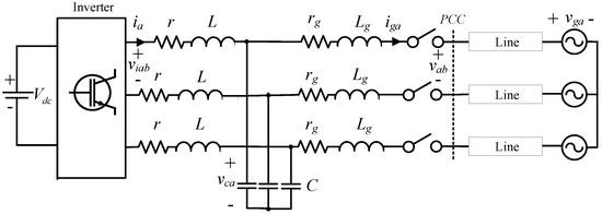
Figure 1.
Three-phase inverter connected to the grid through an filter.
2.2. Dynamic Modeling in the SRF Using DSC Method
In this paper the clockwise SRF transformation is considered. In order to align phase a to the axis, can be selected as in the generic transformation presented in [27]
Following to the transformation, the sequential transformation for the clockwise SRF takes the form:
The matrix occurs from the DSC method which is preferred in this paper because it is faster compared to the methods using low-pass filters [5]. Note that this matrix is different when anti-clockwise SRF is employed while for details on obtaining this matrix and a comparison with the low pass filtering method, the reader is referred to [28]. is then followed by the rotating transformation
where for the positive sequence and for the negative sequence. Hence, considering with and then the complete transformation can be described for a cosinusoidal three-phase voltage variable from the equation
where and By applying the above transformation to the three-phase current and voltage quantities of the system, the SRF-based dynamic equations of the three-phase grid-tied inverter are obtained as
where and are the positive and negative sequence -axis components of the inverter voltage and represent the control inputs of the system. For the ± and ∓ signs that appear in the coupling terms in Equations (2)–(7), the top operator corresponds to the positive sequence and the bottom one to the negative sequence. The instantaneous real and reactive power injected to the grid can be calculated from
where
since is always zero from Equation (1) while are oscillation terms with zero average value [5,6,9]. The VUF can be defined now at the PCC as
while is equivalently derived for the grid side [29,30].
2.3. Problem Formulation
The main goal in this paper is to design a controller that provides support to the grid, under both normal conditions (droop control concept) and faulty conditions (voltage support concept) while boundedness should be proven for the grid current at all times, even during transients. A novel control concept was recently proposed in [15], where droop control is considered in order to mimic the dynamic response of synchronous generators and support the grid voltage and frequency regulation. Furthermore, an inherent current limitation is achieved at all times without using any saturation units but based on the ISS property of the closed-loop system. However, apart from the desired current limitation, according to the voltage support concept, a grid-connected inverter should have support capability when faults occur at the grid in terms of positive sequence voltage increase and negative sequence voltage elimination, aiming to restore the voltage to its pre-fault conditions [18,20]. Since controlling the negative sequence powers is inevitable to mitigate the negative sequence voltage at the PCC under unbalanced faults, a current limitation should be also applied at the negative sequence current while a more sophisticated algorithm is required to optimally allocate the maximum current of each sequence. To address the stated problem, a new droop control structure for three-phase inverters is proposed in the sequel to guarantee a limit for the total grid current and closed-loop asymptotic stability while maximizing the voltage support under both balanced and unbalanced faults.
3. The Proposed Controller
The proposed controller consists of two inner-loop controllers, i.e. current and voltage control, designed in the frame and two novel outer-loop controllers in the SRF (in the positive and negative sequence), which include the droop control concept and inherently limit the grid current in both sequences.
3.1. Inner-Loop Controllers
The current controller of the inner control loop takes the form
where PR controllers are applied to regulate to and to Similarly, the voltage controller, from which and are obtained, is described through the equations
where the reference values and are defined from the values and (generated by the positive and negative sequence outer-loop controllers) transformed to . Note that as in typical multi-loop controller applications, the PR controller gains can be suitably selected such that the current controller settles much faster than the voltage controller which settles much faster than the outer-loop controllers. Thus, for the outer-loop controllers design, which operate in a slower time scale, it is reasonable to assume that and quickly track and . This is a common assumption for the inner-loop controllers used in DERs applications and further analysis can be found in [26].
3.2. Positive Sequence Current-Limiting Droop Control
The positive sequence outer-loop controller consists of a droop-based power controller to support the grid. Since apart from the droop operation, a grid current limitation should be embedded through the power controller, inspired by [15], a virtual resistance should be introduced through the control design. Furthermore, to realize current limitation, the controller states should be bounded in a range set by the operator. In order to avoid the possible instability issues that may occur when using saturation units, for the boundedness of the controller states, the BIC structure from [31] is adopted here. Following the introduction of the inner-loop controller in the previous subsection, the power controller will be directly applied to the capacitor voltage of the filter through controlling the reference capacitor voltage values and . The proposed controller is described by the following equations
where is a constant virtual resistance and are virtual voltages applied to each axis which change according to the expressions
where are positive constants and
where is the RMS nominal voltage in the positive sequence, n, m are the droop coefficients, while the powers are being measured from and by using the steady-state current values (this will be further explained in Section 3.4). Hence, at the steady-state and thus achieving the desired droop control operation, while the expressions of and are used to facilitate the stability analysis, as explained in the sequel. The positive sequence reference real and reactive power are denoted as and respectively. It should be highlighted that due to the virtual resistance introduced by the proposed controller, the and droop expressions are adopted here. Through the functions (18) and (19), the PQ-set and PQ-droop control modes are inherited in the control system. In these two control modes, the inverter either regulates the real and reactive power to their reference values , , when the terms and are removed from (18) and (19), respectively, or supports the grid voltage and frequency regulation through droop control. For the dynamics of the virtual voltages and in Equations (14) and (15), the bounded integral controller (BIC), proposed in [31], is adopted in order to guarantee the boundedness of and without using any saturated integrators that could drive the system to instability. It is noteworthy that in this paper the terms and have been added in (16) and (17) to guarantee attractiveness of the controller states to a desired ellipse on the phase plane. To further explain this, consider the lower bounded function
for the system in Equation (16). The time derivative of W takes the form
which by substituting and from Equation (16), becomes
Furthermore, one can easily show that is bounded. Hence, according to the “Lyapunov-Like Lemma” (Lemma 4.3 in [32]), as It is clear from (20) that holds at the set and at the origin. However, regarding the origin, where and it can be easily proven that it is an unstable equilibrium point, from Theorem 4.4 in [32], by considering the continuously differentiable function Thus, starting from any initial conditions and inside or on the ellipse except from the origin, the states and will be quickly attracted on E and remain on the curve thereafter ensuring that Note that the positive parameter represents the horizontal radius of the ellipse E and when it varies, it becomes clear from (20), that and will quickly converge to a new ellipse. The larger the the faster the convergence. This enables an adaptation of the upper and lower bounds of A similar analysis holds for and guaranteeing that
3.3. Negative Sequence Current-Limiting Control
The proposed current-limiting controller in the negative sequence is designed in a similar form and aims at regulating the negative sequence grid current. Hence it can be obtained as follows
where similarly to the positive sequence controller, is a constant virtual resistance and are virtual voltages applied to each axis which change according to the expressions
where and are the current reference values which, can be realized by equating the and formulas from Equations (8) and (9) with their reference values and while are positive constants. As one can see, through the proposed controller, the expressions and which represent a good approximation of the steady-state negative sequence current values (see Section 3.4) can be regulated to the reference values and Through this control structure, and can track their reference values which can be computed to optimally eliminate the negative sequence voltage. Following a similar analysis to the positive sequence controller, it can be proven that which facilitates the desired current limitation. The methodology for generating and and the current-limiting property are explained in the sequel.
3.4. Current-Limiting Property
By substituting the proposed controller (14), (15), (21) and (22) into the system dynamics (4) and (5), the closed-loop system takes the form
The Equations (25) and (26) are the derived dynamics of the grid current in both sequences. From (25) and (26) the steady-state value of the grid currents can be approximated from and considering that which can be achieved by appropriately selecting the virtual resistances which represent controller parameters. This is why the previous expressions are used in Equations (18), (19), (23) and (24). Taking into account that let us consider the continuous differentiable function
for the system in Equation (25).
The time derivative of V becomes
Thus,
which proves that system (25) is input-to-state stable (ISS) by considering as the input. Since it is proven that then will be bounded for all More precisely, it will hold that
with the condition that initially This holds true because the set is invariant. Hence, if and are selected as and then and Since the same analysis and same result holds for the q axis current as well, it is concluded that
The reason is used in and the way and are selected online, are further explained in Section 4.2.
4. Voltage Support Concept-Based Operation under Grid Faults
4.1. Fault-Ride-Through Operation
Fault-ride-through guidelines have been recently proposed in order to standardize the way DERs should provide support under grid faults. In particular, during grid voltage drops, DERs should provide voltage support through reactive power injection instead of getting disconnected due to tripping of the inverter. In a wider manner, the most common support technique is the “voltage support concept” where maximum available power is injected to the grid in order to increase the voltage level at the PCC [20]. To understand this, consider the voltage difference between the PCC and the grid and assuming a resistive-inductive line with resistance and inductance let us use the approximation of this voltage difference as it is commonly presented in the literature [33,34]
Interested readers can obtain this approximation by using the equations that relate the magnitudes of the PCC and grid voltages according to the current real and reactive components, as shown in [18,35,36].
Since power lines are most of the times considered as predominantly inductive, it can be understood from Equation (27) that reactive power affects more drastically the PCC voltage and thus, by injecting reactive power we can increase the PCC voltage level compared to the faulty grid voltage. In case only resistive or only inductive impedance is considered between the PCC and the grid, the relations between the amplitudes are simplified as presented in [20], thus requiring the injection of only real or reactive power respectively to support PCC by increasing The most commonly used FRT guidelines are those from the German grid code [7] which take the form:
where is the reactive component of the positive sequence grid current and k is the FRT gain with According to Equation (28), it is concluded that and where represents the amount of apparent power assigned to the positive sequence controller during faults, in the case where
Regarding the negative sequence voltage (which is a crucial part of the voltage support concept as well), according to the literature, it can be eliminated by increasing the negative sequence reactive power and decreasing the negative sequence real power. This can be understood either from [18], where equations that involve the magnitude of the PCC voltage are shown to explain the negative sequence voltage elimination concept or from the phasor analysis in [5]. For the calculation of the negative sequence reference powers during unbalanced grid faults, in this paper, a PI controller is applied to generate i.e.,
while
where is a constant and are the proportional and integral gains of the PI controller. Note that Equation (30) represents a decoupling solution based on the line impedance parameters [5,37]. However, accurate knowledge of and is not essential since an estimation of the term is enough. Through Equations (29) and (30), the required negative sequence reference powers to eliminate the PCC negative sequence voltage are acquired. As it is obvious from (29) and (30), considering initially a balanced system, as long as there is no negative sequence voltage at the PCC (balanced system), and thus the inverter injects only positive sequence power. Note that a superiority of the proposed controller compared to existing approaches, is that when the capacity is not enough to track and priority is given to the current limitation property proven in Section 3.4, without switching to different control dynamics or suffering from integrator wind-up issues.
It should be highlighted that methodologies that take into account the line impedance have been also applied for positive sequence voltage support, see for example [18,36]. In this case, decoupling based on the line impedance parameters is achieved in the positive sequence as well and thus, Equation (27) does not represent an assumption since it expresses accurately the voltage difference. However, since the FRT is an essential standard in most of the grid codes nowadays, it is adopted for the positive sequence voltage support in this paper, as in [5]. Note though that if required, and formulas can be easily modified and be determined according to and instead of the FRT guidelines.
4.2. Online Adaptation of and
In this paper, the grid current limitation is inherently applied through the outer-loop controllers and not through saturated integrators in the inner loop. Thus, a proper selection of the maximum available current in each sequence needs to take place by proposing an algorithm that defines the values and To realize the current allocation, priority is given to the positive sequence voltage regulation by means of supporting the positive sequene capacitor voltage so that when we can achieve or which through Equation (27) can be written as
if the voltage difference is selected as This methodology is employed since in contrary to [24], the aim here is to provide a non dynamic method of adjusting the positive and negative sequence maximum currents and furthermore, is considered unknown. Otherwise the positive sequence voltage support could be applied at the PCC voltage. By recalling the and formulas derived from (28), expression (31) results to
Thus, we can select
where is the p.u. voltage drop of the RMS voltage at the PCC. Note that Equation (32) is valid only when (from Equation (28)) and since in the absence of negative sequence voltage, all the available current is assigned to the positive sequence. is then passed through a saturator that ensures that Opposed to conventional current-limiting control schemes that apply a saturator on the current dynamics, here the function being saturated is not dynamic and thus does not suffer from integrator wind-up. Then, according to the theory presented in [22,23], which shows that the total current of any phase has a maximum value even if unbalanced current is injected to the grid, can be set as
When current allocation has taken place, the value can be easily selected as and the positive sequence reference powers can be calculated according to the FRT guidelines in Equation (28), while when from Equation (32) or due to the saturator, then and Since the maximum current for each sequence is now defined according to the voltage drop, the proposed controller dynamics in (16), (17), (23) and (24) can be adapted online through the expressions Opposed to the work presented in [15,38], here the proposed design enables the adaptation of the controller parameters and and the controller states are attracted on any ellipse E with varying horizontal radius ( or ) as analytically proven in Section 3.2. The positive sequence maximum current is set as the amplitude and not the RMS value in order to allow for the FRT. However, since it holds that the maximum RMS current will never be violated at the steady-state, while during transients, through the input-to-state stability property of the closed-loop current dynamics, it is proven that it remains below the value (worst-case scenario), which commercial inverters can handle [39]. Finally, during normal grid conditions, can be simply selected as to ensure current limitation under the value at all times. The implementation of the proposed control approach is depicted in Figure 2, where the control part generating the positive and negative sequence reference powers and the maximum currents is denoted as the FRT block, which is shown in Figure 3.
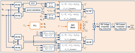
Figure 2.
Implementation diagram of the proposed controller.
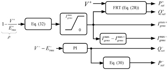
Figure 3.
Fault-ride-through (FRT) Block.
5. Stability Analysis
After applying the proposed controller into the three-phase inverter system, the closed-loop dynamics are given by (16), (17), (23)–(26). The state vector of the closed-loop system, for both sequences, takes the form where Consider now any steady-state equilibrium point with i.e., where the voltage and frequency at the PCC are assumed constant (not necessarily equal to their rated values). By defining and then the closed-loop dynamics (16), (17), (23)–(26) can be written in the following interconnected system form
where the equilibrium has been shifted at the origin. According to Lemma 5.6 in [40], if the system (34) with the as input, is locally input-to-state stable and the origin of the system (35) is asymptotically stable, then the origin of the interconnected systems (34) and (35) is asymptotically stable.
Since the characteristic matrix of the grid current dynamics is diagonal with all elements being negative, then the system (34) is bounded-input bounded state stable with respect to the input which means that (34) is ISS. Then, for the dynamics of the control systems (16), (17), (23) and (24), the Jacobian matrix of (35) becomes
where
with and Since is a block diagonal matrix, we can investigate the system matrices and independently. The characteristic polynomials of these two matrices take the form
Hence, the condition to guarantee asymptotic stability for any equilibrium point of the closed-loop system in the bounded operating range is
which is always true regardless of the voltage level. Opposed to the majority of the conventional approaches that use root locus analysis and guarantee stability of a given equilibrium point under the specific parameters of the inverter and the grid, here the proposed controller guarantees asymptotic stability of any equilibrium point in the bounded operating range. In addition, an inherent current-limiting property and an enhanced operation under grid faults is achieved in a unified control structure, which highlights the novelty of the proposed control scheme.
6. Validation through Real-Time Results
In order to validate the proposed control approach, a three-phase inverter connected to the grid, as shown in Figure 1, and equipped with the controller proposed in this paper, is tested using an OPAL-RT OP4500 real-time digital simulator. The parameters of the controller and the power system are given in Table 1. In the next subsections, the performance of the proposed controller will be showcased under various normal and abnormal grid conditions.

Table 1.
System and controller parameters.
6.1. Balanced Operation
Firstly, the operation of the grid-connected inverter equipped with the proposed controller will be tested under balanced grid conditions. The switch between the filter and the PCC is initially open, and then closes at , while at the same time the controller is enabled with the reference values and having the values of and respectively. The controller operates initially in the PQ-set mode and regulates and to their desired values, as shown in Figure 4. In the same figure, and can be observed as well. At is changed to and the reactive power injection is accordingly modified while at is set as Since the PQ-set operation is now verified, at and the real and reactive power droop control modes are enabled respectively. One can see that both the real and the reactive power drop since at that time, the grid operates with a slightly higher value of RMS grid voltage compared to the nominal () and a slightly lower than the nominal grid frequency (). At a balanced grid voltage drop of is applied in order to test the operation under faulty grid conditions. At the initial transient, it can be observed in Figure 4, that reaches the value of while it never violates the ultimate bound of
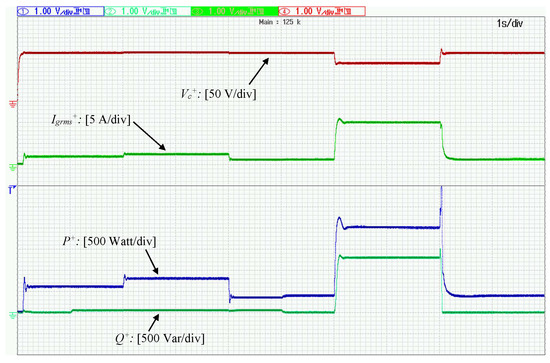
Figure 4.
Operation under balanced conditions with a balanced voltage drop at 6 s.
Following to the transient, the RMS value of the grid current is regulated to its maximum value of as it has been analytically proven in this paper, while and are regulated according to the FRT, thus achieving grid support and inverter protection simultaneously. When the fault is self-cleared at and return smoothly to their original values according to the droop control.
6.2. Operation under Single-Phase Voltage Sag
In order to test the operation of the proposed controller under unbalanced faults, a single-phase voltage sag is applied on with its RMS value dropping by which leads to while the inverter is operating with droop control. As it can be observed in Figure 5, the current allocation algorithm leads the RMS currents to the values and . It should be noted that according to the proposed controller operation, the components and are tracking their maximum values from Equations (32) and (33) during voltage drops (unless the desired regulation has been achieved with less than the maximum negative sequence current). Hence, the total current is regulated close to its maximum value but without exceeding it. The primary objective of the proposed controller is achieved since as it is depicted in Figure 5, is regulated to This verifies the proper selection of the value which further leads to the calculation, while the rest of the available inverter capacity is assigned to negative sequence current controller so that shown in Figure 5, is eliminated as much as possible. The real and reactive power components injected to the grid according to Equation (28) and Equations (29) and (30) are depicted in Figure 6 while, even if the proposed controller does not deal directly with the VUF but aims to increase the positive sequence voltage and eliminate the negative sequence voltage, in this certain scenario, it can be seen in Figure 7 that at the PCC is eliminated by 7% when compared to At the steady-state, and are not tracked since priority is given to the current-limiting property. However, if greater capacity was available, such that and would be regulated to their reference values. After the fault is self-cleared and the positive sequence components are driven to their initial values according to droop control while the negative sequence components are driven to 0.
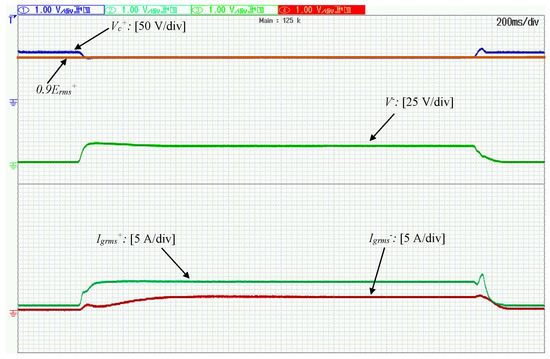
Figure 5.
Operation under single-phase voltage drop (): Positive and negative sequence RMS voltages and currents.
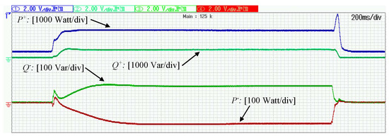
Figure 6.
Operation under single-phase voltage drop (): Injected powers.
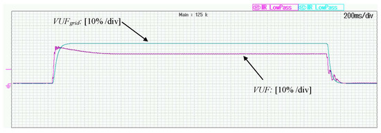
Figure 7.
Operation under single-phase voltage drop (): Voltage unbalance factors.
Note that during the clearing transient, the value reaches the value for however, it never exceeds its ultimate bound during transients set at as proven in the theoretic analysis presented in this paper.
6.3. Operation under Two-Phase Voltage Sag
To further demonstrate the operation of the proposed controller under unbalanced faults, a two-phase voltage sag is now applied, with the RMS values of and dropping so that and leading to while the inverter is operated in the droop control mode. As mentioned before, the maximum current assigned to the positive sequence controller is tracked by the controller leading to in order to optimize the support operation and thus, is regulated to as shown in Figure 8. The the rest of the available current, is assigned to the negative sequence current controller which leads to thus, managing to eliminate the negative sequence voltage, shown in Figure 8. Hence, the total current never violates its maximum value The powers injected to the grid in both sequences can be observed in Figure 9 while the is eliminated by 7% compared to the as depicted in Figure 10. After the fault is self-cleared and the positive sequence components are driven to their initial values according to droop control while the negative sequence components are driven to 0. It is underlined that during the clearing transient, the addition reaches the value of for less than without ever violating the ultimate bound for transient currents, set at
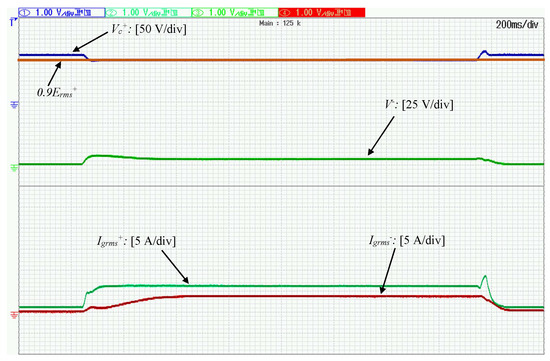
Figure 8.
Operation under two-phase voltage drop ( and ): Positive and negative sequence RMS voltages and currents.
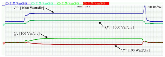
Figure 9.
Operation under two-phase voltage drop ( and ): Injected powers.
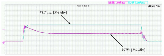
Figure 10.
Operation under two-phase voltage drop ( and ): Voltage unbalance factors.
7. Conclusions
In this paper, a new control concept that offers an inherent current limitation at all times is proposed for three-phase grid-tied droop-controlled inverters. The proposed controller complies with the latest grid code requirements and apart from droop control, voltage support through maximum power injection is achieved under both balanced and unbalanced grid faults. To accomplish this, two novel outer-loop controllers are applied to both positive and negative sequence while boundedness of the grid current is achieved during transients without the need of saturation units. A new way of dividing the available current into the positive and negative sequence is proposed so that positive sequence voltage is increased and the negative sequence voltage is eliminated. Asymptotic stability of any equilibrium point of the closed-loop system within the bounded operating range is proven without assuming knowledge of the system parameters. The proposed control approach is verified through extensive real-time simulation results.
Future research will focus on the experimental validation of the proposed control approach and the comparison with other techniques that aim to implement the voltage support concept under balanced and unbalanced grid faults.
Author Contributions
The authors equally contributed in performing the system modeling and the stability analysis, proposing the controller and obtaining the real-time simulation results. All authors proofread and approved the publication.
Funding
This work was supported by the EPSRC under Grant No. EP/S001107/1.
Acknowledgments
The authors would like to thank OPAL-RT Technologies for the donation of the OP4500 real-time digital simulator.
Conflicts of Interest
The authors declare no conflict of interest.
Nomenclature
| to transformation | |
| Sequential transformation | |
| Rotating transformation for each sequence | |
| Angular PCC frequency | |
| Rated angular frequency | |
| Positive sequence real and reactive power | |
| Negative sequence real and reactive power | |
| Positive sequene RMS PCC voltage | |
| Negative sequence RMS PCC voltage | |
| Positive sequence rated RMS voltage | |
| Negative sequence rated RMS voltage | |
| Positive sequence real and reactive power reference values | |
| Negative sequence real and reactive power reference values | |
| Real and reactive power droop coefficients | |
| Positive sequence maximum RMS grid current | |
| Negative sequence maximum RMS grid current | |
| Line resistance | |
| Line reactance | |
| Grid voltage drop in p.u. | |
| k | FRT gain |
References
- Xue, Y.; Guerrero, J.M. Smart inverters for utility and industry applications. In Proceedings of the PCIM Europe 2015; International Exhibition and Conference for Power Electronics, Intelligent Motion, Renewable Energy and Energy Management, Nuremberg, Germany, 19–21 May 2015; pp. 1–8. [Google Scholar]
- Chen, J.; Hou, S.; Li, X. Decentralized circulating currents suppression for paralleled inverters in microgrids using adaptive virtual inductances. Energies 2018, 11, 1725. [Google Scholar] [CrossRef]
- Guerrero, J.M.; de Vicuna, L.G.; Matas, J.; Castilla, M.; Miret, J. Output impedance design of parallel-connected UPS inverters with wireless load-sharing control. IEEE Trans. Ind. Electron. 2005, 52, 1126–1135. [Google Scholar] [CrossRef]
- Guerrero, J.M.; Matas, J.; de Vicuna, L.G.; Castilla, M.; Miret, J. Decentralized control for parallel operation of distributed generation inverters using resistive output impedance. IEEE Trans. Ind. Electron. 2007, 54, 994–1004. [Google Scholar] [CrossRef]
- Zhao, X.; Guerrero, J.M.; Savaghebi, M.; Vasquez, J.C.; Wu, X.; Sun, K. Low-voltage ride-through operation of power converters in grid-interactive microgrids by using negative-sequence droop control. IEEE Trans. Power Electron. 2017, 32, 3128–3142. [Google Scholar] [CrossRef]
- Piya, P.; Ebrahimi, M.; Karimi-Ghartemani, M.; Khajehoddin, S.A. Fault ride-through capability of voltage-controlled inverters. IEEE Trans. Ind. Electron. 2018, 65, 7933–7943. [Google Scholar] [CrossRef]
- EON Netz. Grid Code, High and Extra High Voltage; Technical Report; German TSO; EON Netz: Bayreuth, Germany, 2016. [Google Scholar]
- Tafti, H.D.; Maswood, A.I.; Konstantinou, G.; Pou, J.; Kandasamy, K.; Lim, Z.; Ooi, G.H.P. Low-voltage ride-thorough capability of photovoltaic grid-connected neutral-point-clamped inverters with active/reactive power injection. IET Renew. Power Gen. 2017, 11, 1182–1190. [Google Scholar] [CrossRef]
- Camacho, A.; Castilla, M.; Miret, J.; Borrell, A.; de Vicuna, L.G. Active and reactive power strategies with peak current limitation for distributed generation inverters during unbalanced grid faults. IEEE Trans. Ind. Electron. 2015, 62, 1515–1525. [Google Scholar] [CrossRef]
- Xin, H.; Huang, L.; Zhang, L.; Wang, Z.; Hu, J. Synchronous instability mechanism of P-f droop-controlled voltage source converter caused by current saturation. IEEE Trans. Power Syst. 2016, 31, 5206–5207. [Google Scholar] [CrossRef]
- Shuvra, M.A.; Chowdhury, B. Distributed dynamic grid support using smart PV inverters during unbalanced grid faults. IET Renew. Power Gen. 2019, 13, 598–608. [Google Scholar] [CrossRef]
- Paquette, A.D.; Divan, D.M. Virtual impedance current limiting for inverters in microgrids with synchronous generators. IEEE Trans. Ind. Appl. 2015, 51, 1630–1638. [Google Scholar] [CrossRef]
- Bottrell, N.; Green, T.C. Comparison of current-limiting strategies during fault ride-through of inverters to prevent latch-up and wind-up. IEEE Trans. Power Electron. 2014, 29, 3786–3797. [Google Scholar] [CrossRef]
- Lu, X.; Wang, J.; Guerrero, J.M.; Zhao, D. Virtual-impedance-based fault current limiters for inverter dominated AC microgrids. IEEE Trans. Smart Grid 2018, 9, 1599–1612. [Google Scholar] [CrossRef]
- Zhong, Q.C.; Konstantopoulos, G.C. Current-limiting droop control of grid-connected inverters. IEEE Trans. Ind. Electron. 2017, 64, 5963–5973. [Google Scholar] [CrossRef]
- Paspatis, A.G.; Konstantopoulos, G.C. SRF-based current-limiting droop controller for three-phase grid-tied inverters. In Proceedings of the IECON 2018—44th Annual Conference of the IEEE Industrial Electronics Society, Washington, DC, USA, 21–23 October 2018; pp. 282–287. [Google Scholar] [CrossRef]
- Camacho, A.; Castilla, M.; Miret, J.; de Vicuna, L.G.; Andres, G.L.M. Control strategy for distribution generation inverters to maximize the voltage support in the lowest phase during voltage sags. IEEE Trans. Ind. Electron. 2018, 65, 2346–2355. [Google Scholar] [CrossRef]
- Camacho, A.; Castilla, M.; Miret, J.; de Vicuna, L.G.; Guzman, R. Positive and negative sequence control strategies to maximize the voltage support in resistive—Inductive grids during grid faults. IEEE Trans. Power Electron. 2018, 33, 5362–5373. [Google Scholar] [CrossRef]
- Nejabatkhah, F.; Li, Y.W.; Wu, B. Control strategies of three-phase distributed generation inverters for grid unbalanced voltage compensation. IEEE Trans. Power Electron. 2016, 31, 5228–5241. [Google Scholar] [CrossRef]
- Jia, J.; Yang, G.; Nielsen, A.H. A review on grid-connected converter control for short-circuit power provision under grid unbalanced faults. IEEE Trans. Power Deliv. 2018, 33, 649–661. [Google Scholar] [CrossRef]
- Popadic, B.; Dumnic, B.; Milicevic, D.; Katic, V.; Sljivac, D. Grid-connected converter control during unbalanced grid conditions based on delay signal cancellation. Int. Trans. Electr. Energy Syst. 2018, 28, e2636. [Google Scholar] [CrossRef]
- Acharya, S.; Moursi, M.S.E.; Al-Hinai, A.; Al-Sumaiti, A.S.; Zeineldin, H. A control strategy for voltage unbalance mitigation in an islanded microgrid considering demand side management capability. IEEE Trans. Smart Grid 2018, 1. [Google Scholar] [CrossRef]
- Awadhi, N.A.; Moursi, M.S.E. A novel centralized PV power plant controller for reducing the voltage unbalance factor at transmission level interconnection. IEEE Trans. Energy Convers. 2017, 32, 233–243. [Google Scholar] [CrossRef]
- Moawwad, A.; Moursi, M.S.E.; Xiao, W. A novel transient control strategy for VSC-HVDC connecting offshore wind power plant. IEEE Trans. Sustain. Energy 2014, 5, 1056–1069. [Google Scholar] [CrossRef]
- Ojo, Y.; Schiffer, J. Towards a time-domain modeling framework for small-signal analysis of unbalanced microgrids. In Proceedings of the 2017 IEEE Manchester PowerTech, Manchester, UK, 18–22 June 2017; pp. 1–6. [Google Scholar] [CrossRef]
- Teodorescu, R.; Liserre, M.; Rodriguez, P. Grid Converters for Photovoltaic and Wind Power Systems; John Wiley & Sons: Hoboken, NJ, USA, 2011. [Google Scholar]
- Bose, B.K. Modern Power Electronics and AC Drives; Prentice Hall PTR: Upper Saddle River, NJ, USA, 2002. [Google Scholar]
- Zhou, Y.; Bauer, P.; Ferreira, J.A.; Pierik, J. Operation of grid-connected DFIG under unbalanced grid voltage condition. IEEE Trans. Energy Convers. 2009, 24, 240–246. [Google Scholar] [CrossRef]
- El-Naggar, A.; Erlich, I. Control approach of three-phase grid connected PV inverters for voltage unbalance mitigation in low-voltage distribution grids. IET Renew. Power Gen. 2016, 10, 1577–1586. [Google Scholar] [CrossRef]
- Sun, Y.; Li, P.; Li, S.; Zhang, L. Contribution determination for multiple unbalanced sources at the point of common coupling. Energies 2017, 10, 171. [Google Scholar] [CrossRef]
- Konstantopoulos, G.C.; Zhong, Q.C.; Ren, B.; Krstic, M. Bounded integral control of input-to-state practically stable nonlinear systems to guarantee closed-loop stability. IEEE Trans. Autom. Control 2016, 61, 4196–4202. [Google Scholar] [CrossRef]
- Slotine, J.J.E.; Li, W. Applied Nonlinear Control; Prantice Hall: Upper Saddle River, NJ, USA, 1991. [Google Scholar]
- Tonkoski, R.; Lopes, L.A.C.; El-Fouly, T.H.M. Coordinated active power curtailment of grid connected PV inverters for overvoltage prevention. IEEE Trans. Sustain. Energy 2011, 2, 139–147. [Google Scholar] [CrossRef]
- Mishra, S.; Mishra, Y. Decoupled controller for single-phase grid connected rooftop PV systems to improve voltage profile in residential distribution systems. IET Renew. Power Gen. 2017, 11, 370–377. [Google Scholar] [CrossRef]
- Garnica, M.; Garcia de Vicuna, L.; Miret, J.; Camacho, A.; Guzman, R. Voltage support experimental analysis of a low-voltage ride-through strategy applied to grid-connected distributed inverters. Energies 2018, 11, 1949. [Google Scholar] [CrossRef]
- Shabestary, M.M.; Mohamed, Y.A.I. Advanced voltage support and active power flow control in grid-connected converters under unbalanced conditions. IEEE Trans. Power Electron. 2018, 33, 1855–1864. [Google Scholar] [CrossRef]
- Camacho, A.; Castilla, M.; Canziani, F.; Moreira, C.; Coelho, P.; Gomes, M.; Mercado, P. Performance comparison of grid-faulty control schemes for inverter-based industrial microgrids. Energies 2017, 10, 2096. [Google Scholar] [CrossRef]
- Dedeoglu, S.; Konstantopoulos, G.C. Three-phase grid-connected inverters equipped with nonlinear current-limiting control. In Proceedings of the 2018 UKACC 12th International Conference on Control (CONTROL), Sheffield, UK, 5–7 September 2018; pp. 38–43. [Google Scholar] [CrossRef]
- SMA. Short-Circuit Currents: Information on Short-Circuit Currents of SMA PV Inverters (Technical Information); Technical Report; SMA: Niestetal, Germany, 2016. [Google Scholar]
- Khalil, H.K. Nonlinear Systems; Prentice Hall: Upper Saddle River, NJ, USA, 1996. [Google Scholar]
© 2019 by the authors. Licensee MDPI, Basel, Switzerland. This article is an open access article distributed under the terms and conditions of the Creative Commons Attribution (CC BY) license (http://creativecommons.org/licenses/by/4.0/).