Installation and Operation of a Solar Cooling and Heating System Incorporated with Air-Source Heat Pumps
Abstract
:1. Introduction
2. Climate Conditions and Building Characteristics
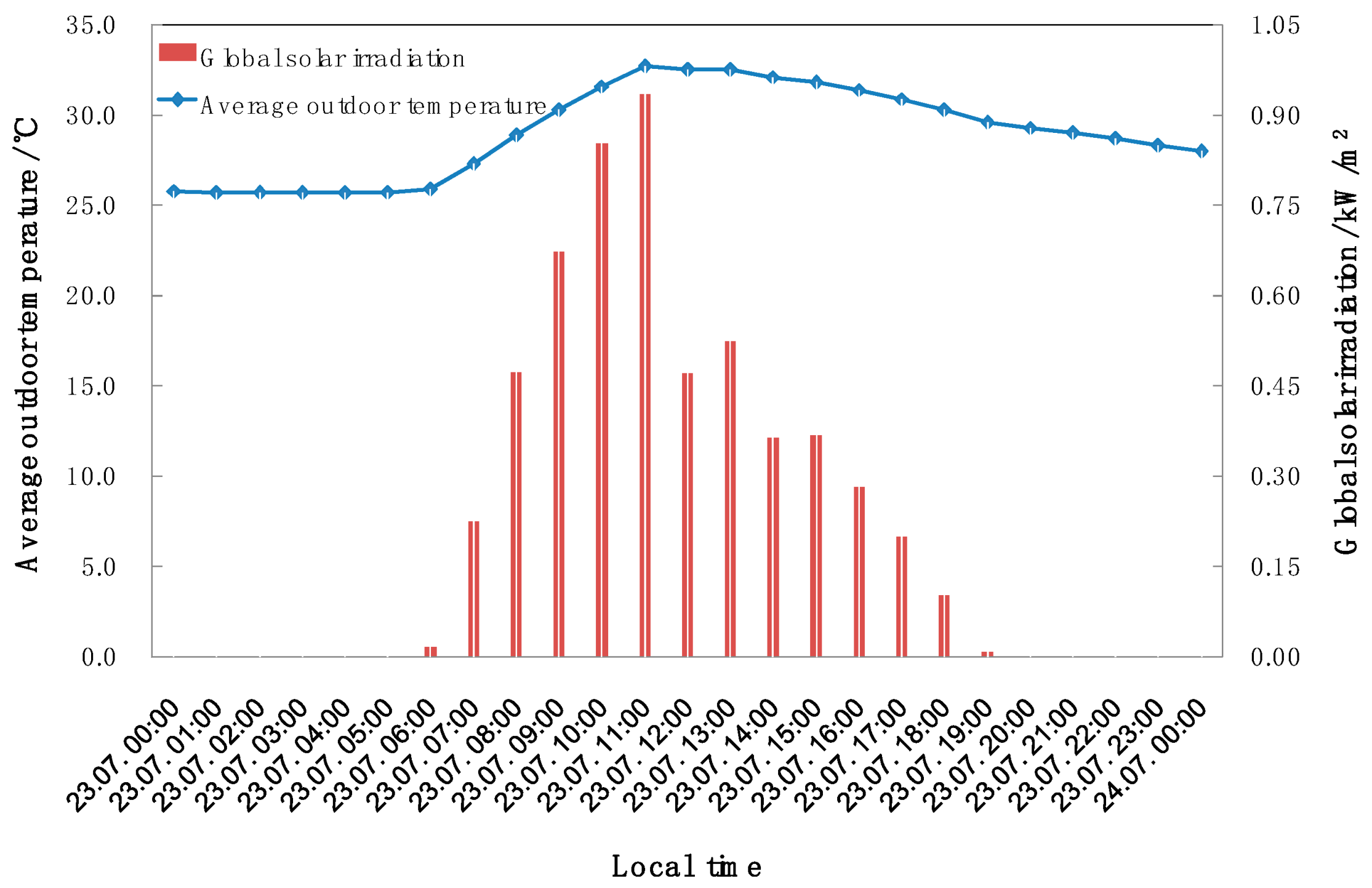
2.1. Climate Conditions
2.2. Building Characteristics
3. System Installation
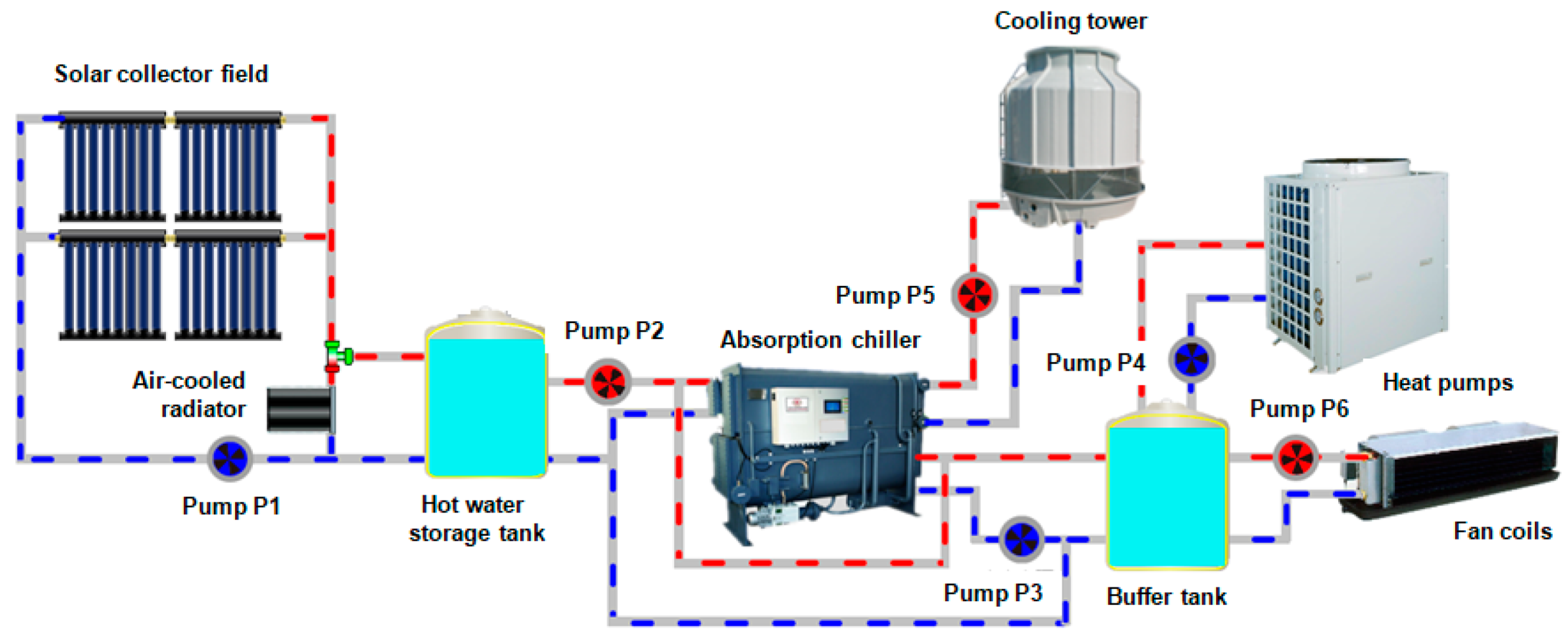
3.1. Description of the System Components
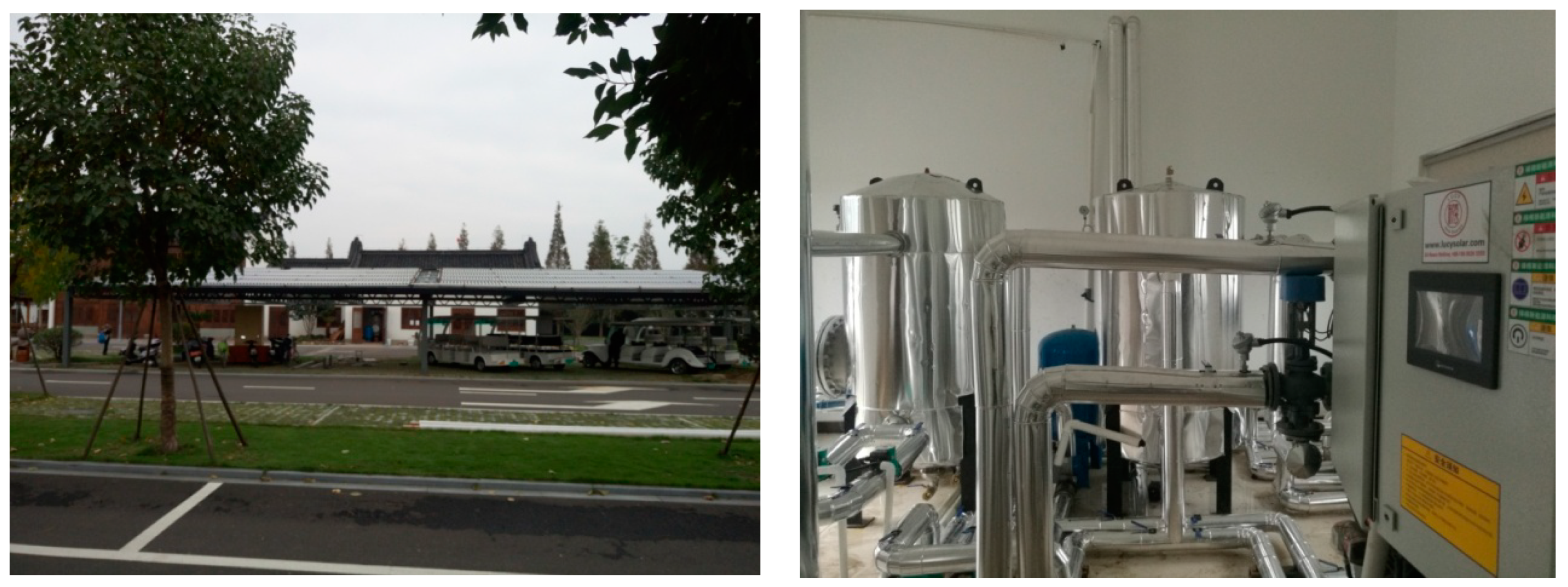
3.1.1. The Solar Collector Field
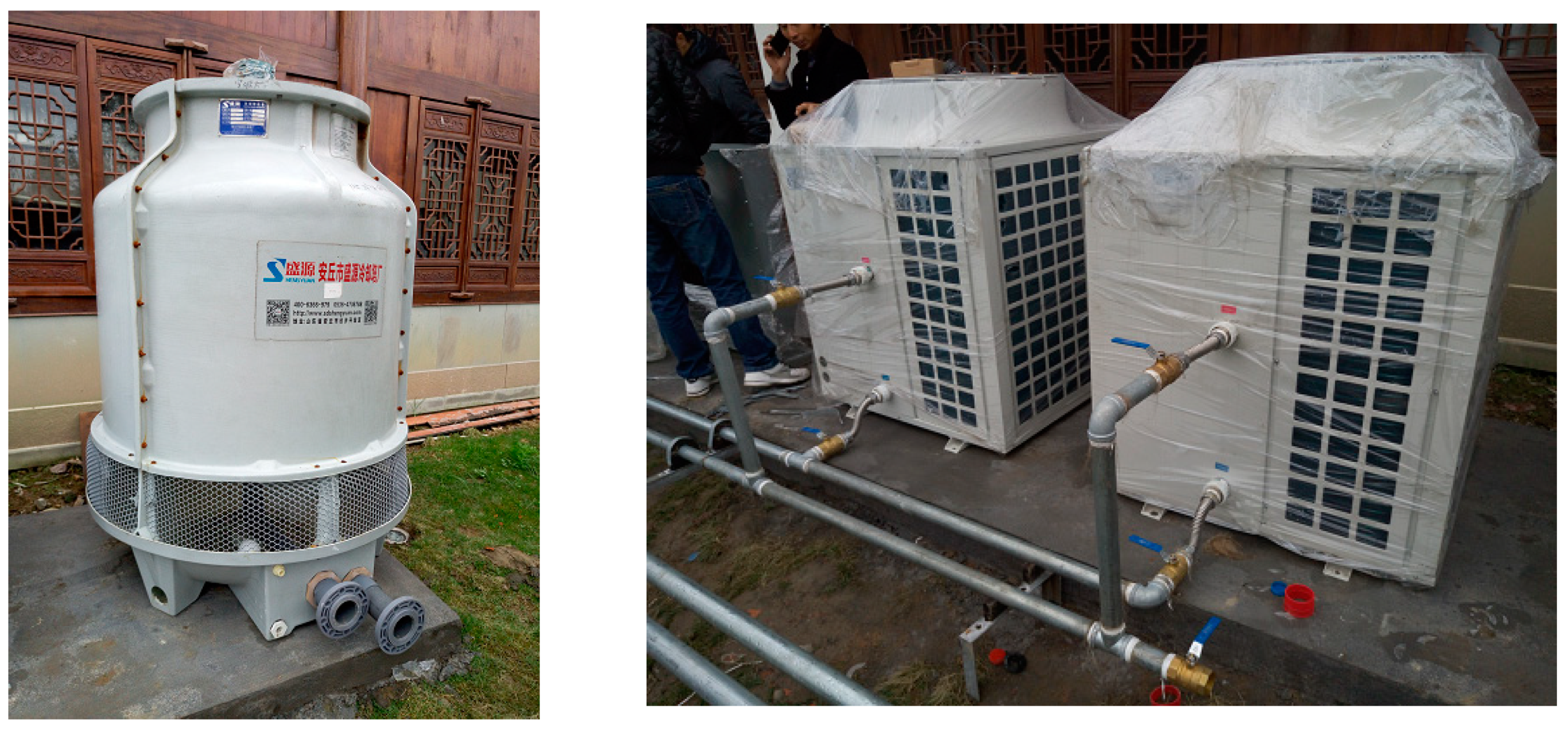
3.1.2. The Absorption Chiller
3.1.3. The Thermal Energy Storage
3.1.4. The Auxiliary System
3.2. Description of the Controlling and Monitoring System
4. Operational Results and Performance Evaluation
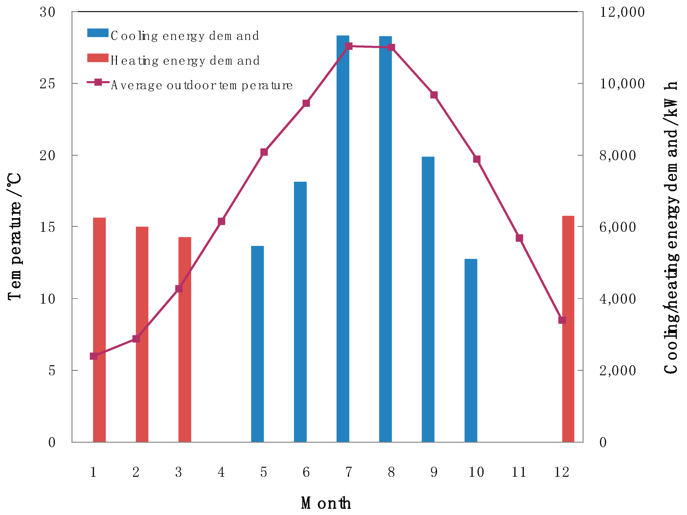
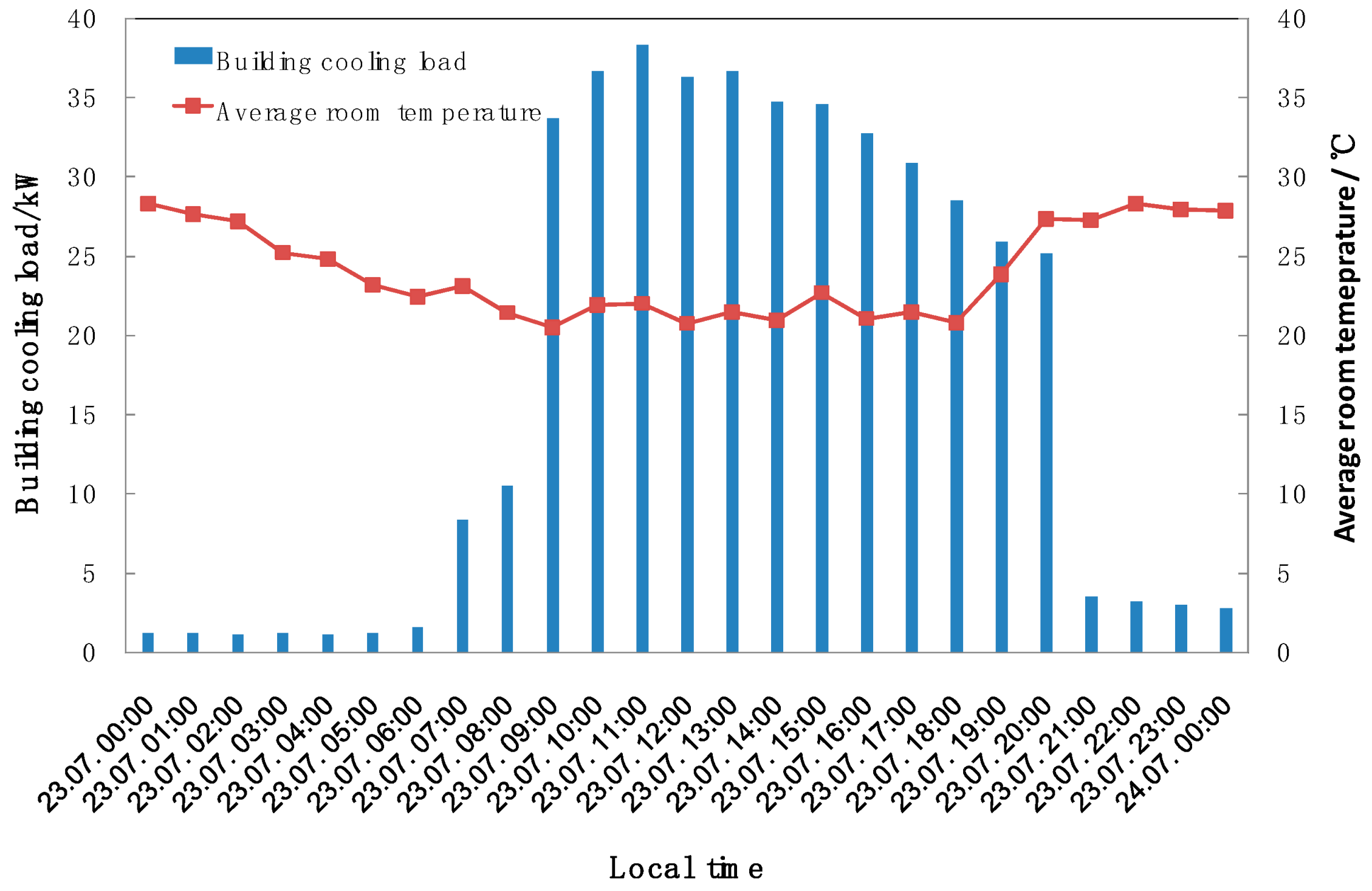
4.1. Building Cooling and Heating Energy Demand and Room Temperature
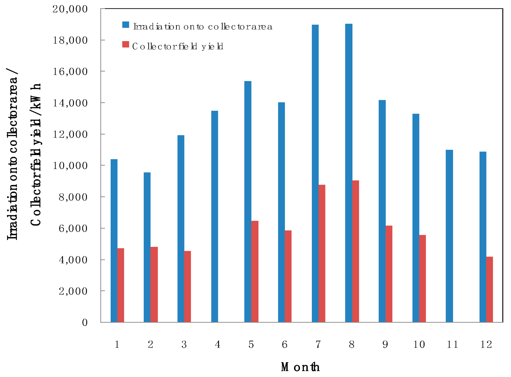
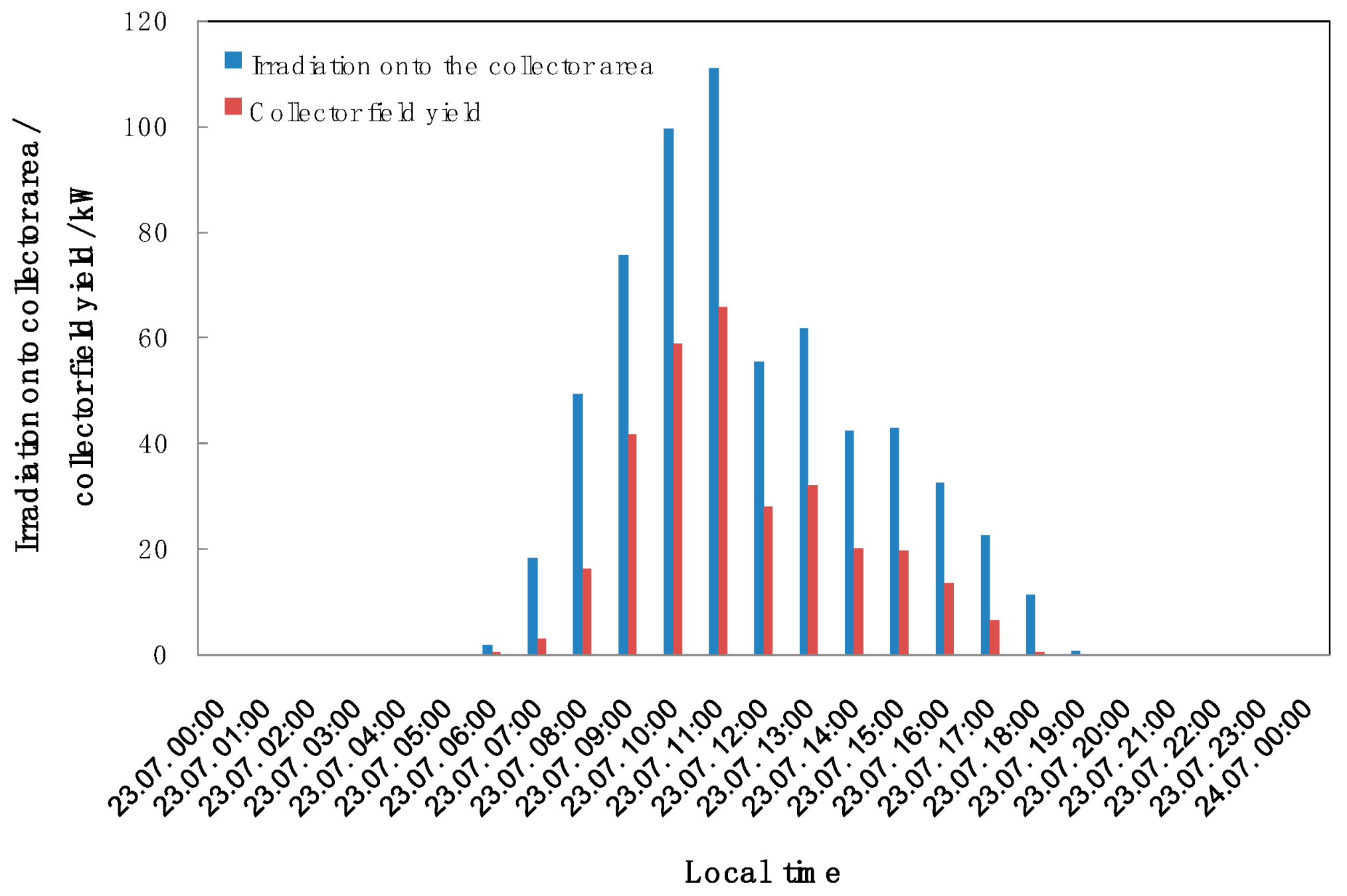
4.2. Solar Collector Field
4.3. Absorption Chiller
4.4. Heat Pumps
4.5. Electricity Savings and Emission Reduction
5. Discussion and Conclusions
- The solar collector field was comprised of 40 all-glass evacuated tube modules with a total aperture area of 120 m2. The annual average collector efficiency was 44%for building cooling and 42% for building heating.
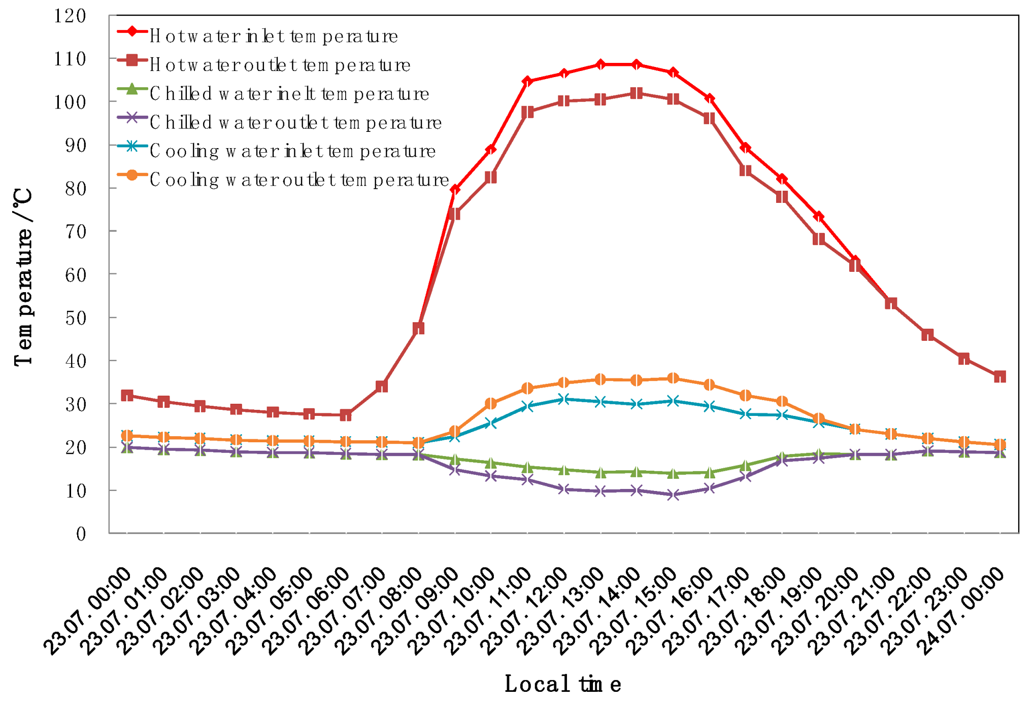
- The single-stage and LiBr–water based absorption chiller had a cooling capacity of 35 kW. The monthly average coefficient of performance COPchiller ranged between 0.68 and 0.76 in 2018. The COPchiller increased with the rising hot water inlet temperature.
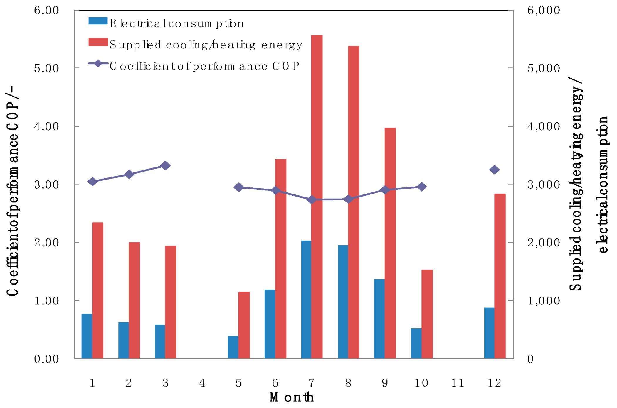
- Two air-source heat pumps each with a rated cooling capacity of 23.8 kW and heating capacity of 33 kW were used as the auxiliary system for the solar cooling and heating installation. The average coefficient of performance COPhp,c was 2.83 in 2018, with minimums of 2.74 and 2.75 in July and August, respectively. The average coefficient of performance for heating COPhp,h was 3.20.
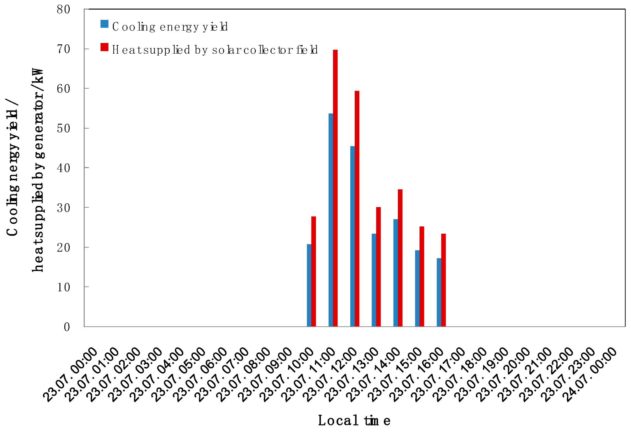
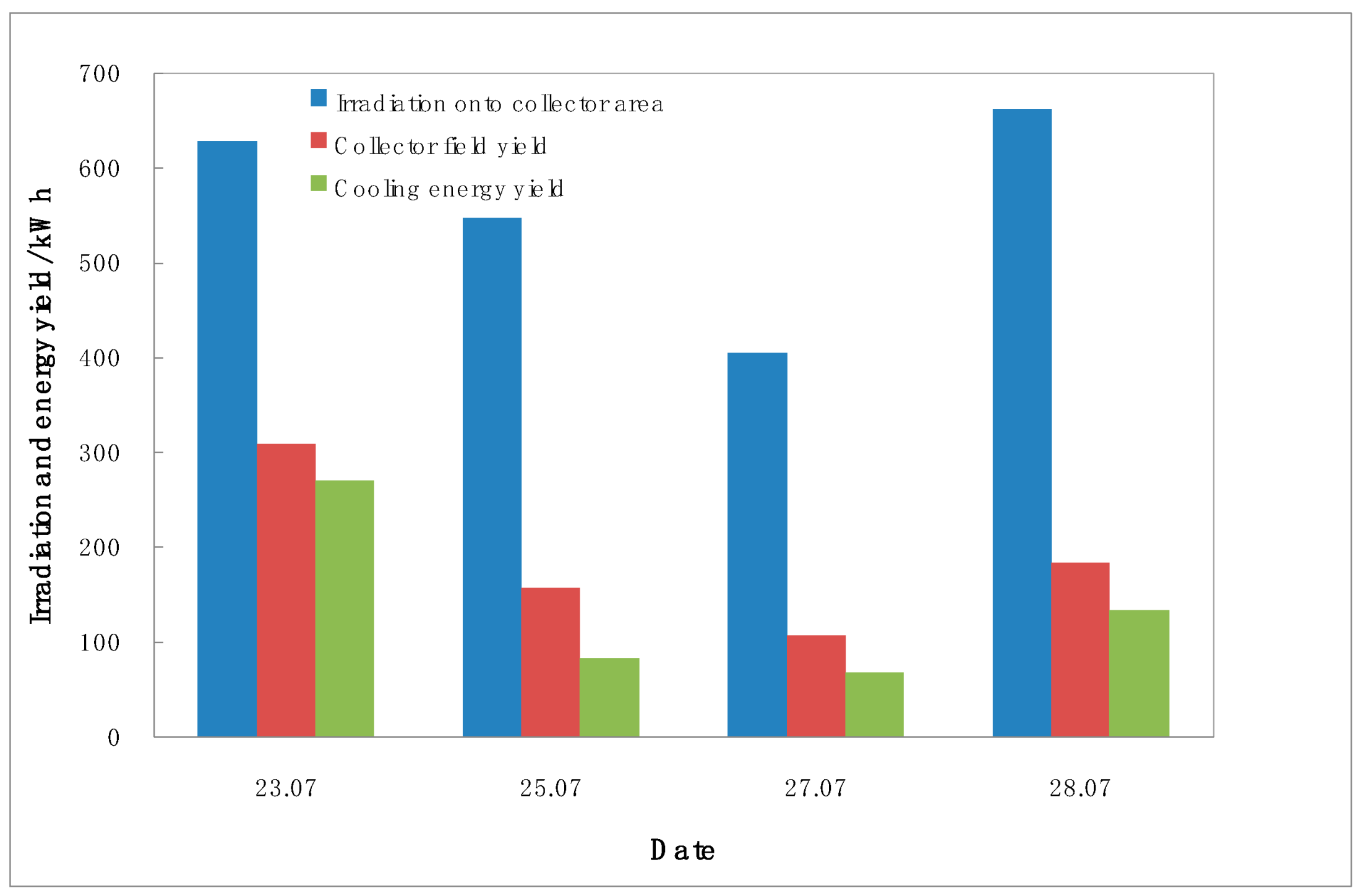
- The energy yields distinctly decreased without the heat pumps as the auxiliary system. In comparison with the case combined with the heat pumps under similar irradiation conditions, the collector field yield and cooling energy yield decreased by more than 40%.
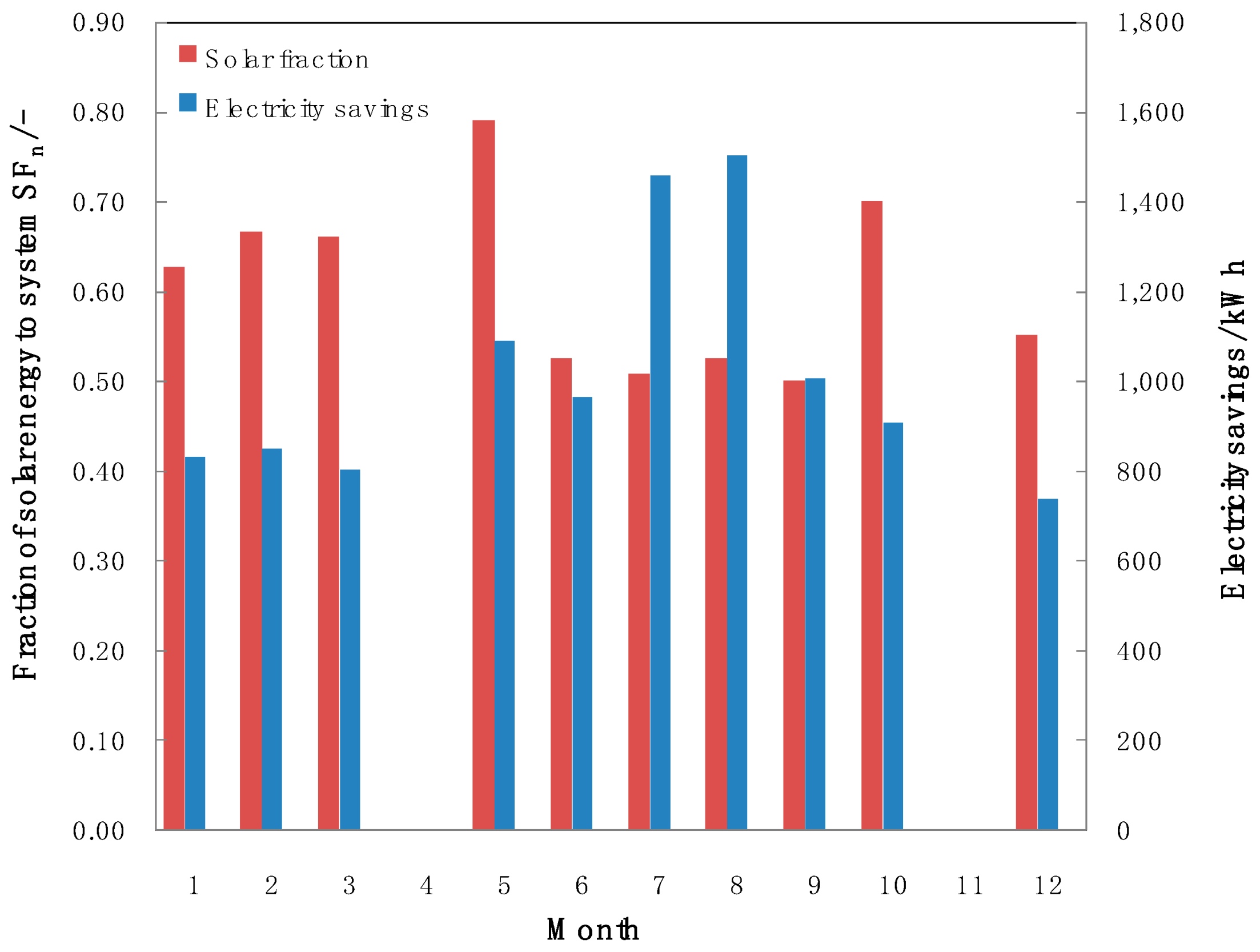
- Two kinds of operational modes were conducted, namely, the building cooling and heating modes. The annual mean solar fractions for cooling and heating were 56.6% and 62.5%, respectively. The yearly electricity saving was 10,158.6 kWh when combined with the solar cooling and heating system, which accounted for 41.1% of the total electricity consumption for building cooling and heating and corresponds to 5445 kg of CO2 emissions prevented from being released into the atmosphere.
Author Contributions
Funding
Acknowledgments
Conflicts of Interest
Nomenclature
| Asolar | Aperture area of solar collectors, m2 |
| COPchiller | Coefficient of performance of the absorption chiller |
| COPhp,c | Coefficient of performance of the heat pump for cooling |
| COPhp,h | Coefficient of performance of the heat pump for heating |
| E1 | Electrical consumption of the heat pumps, kWh |
| F1 | Inlet flow rate of the collector field, kg/s |
| F2 | Hot water inlet flow rate of the absorption chiller, kg/s |
| F3 | Chilled water inlet flow rate of the absorption chiller, kg/s |
| F4 | Inlet flow rate of the fan coils, kg/s |
| Isolar | Solar radiation, W/m2 |
| Qc | Cooling energy generated by the chiller driven by solar, kWh |
| Qh | Heating energy generated by solar, kWh |
| Qsc | Solar energy collected, kWh |
| Qsolar | Total solar energy available, kWh |
| Qt | Total cooling or heating energy used, kWh |
| SFn,c | Coefficient of performance of the heat pumps during the winter heating time |
| SFn,h | Coefficient of performance of the heat pumps during the summer cooling time |
| T0 | Ambient temperature, °C |
| T1 | Temperature of the collector array 1, °C |
| T2 | Temperature of the collector array 2, °C |
| T3 | Outlet temperature of the collector field, °C |
| T4 | Upper layer temperature of the hot water storage tank, °C |
| T5 | Lower layer temperature of the hot water storage tank, °C |
| T6 | Inlet temperature of the collector field, °C |
| T7 | Antifreeze temperature of the collector field, °C |
| T8 | Hot water inlet temperature of the absorption chiller, °C |
| T9 | Hot water outlet temperature of the absorption chiller, °C |
| T10 | Chilled water outlet temperature of the absorption chiller, °C |
| T11 | Chilled water inlet temperature of the absorption chiller, °C |
| T12 | Cooling water outlet temperature of the absorption chiller, °C |
| T13 | Cooling water inlet temperature of the absorption chiller, °C |
| T14 | Upper layer temperature of the buffer tank, °C |
| T15 | Lower layer temperature of the buffer tank, °C |
| T16 | Inlet temperature of the fan coils, °C |
| T17 | Outlet temperature of the fan coils, °C |
| η | Collector efficiency |
References
- Zhao, H.X.; Frédéric, M. A review on the prediction of building energy consumption. Renew. Energ. Rev. 2012, 4, 3586–3592. [Google Scholar] [CrossRef]
- Yang, X.M. The energy consumption and savings of public buildings in Shanghai. Master Thesis, Tongji University, Shanghai, China, 2007. [Google Scholar]
- Mugnier, D. State of the art for solar thermal or PV cooling and refrigeration. In Proceedings of the Solar Heating & Cooling Program SHC 2014 Conference, Beijing, China, 15 October 2014. [Google Scholar]
- Syed, A.; Izquierdo, M.; Rodriguez, P.; Maidment, G.; Missenden, J.; Lecuona, A.; Tozer, R. A novel experimental investigation of a solar cooling system in Madrid. Int. J. Refrig. 2005, 28, 859–871. [Google Scholar] [CrossRef]
- Pongtornkulpanich, A.; Thepa, S.; Amornkitbamrung, M.; Butcher, C. Experience with fully operational solar-driven 10 ton LiBr/H2O single-effect absorption cooling system in Thailand. Renew. Energy 2008, 33, 943–949. [Google Scholar] [CrossRef]
- Rosiek, S.; Batlles, F.Z. Integration of the solar thermal energy in the construction: Analysis of the solar-assisted air-conditioning system installed in CIESOL building. Renew. Energy 2009, 34, 1423–1431. [Google Scholar] [CrossRef]
- Bermejo, P.; Pino, F.J.; Rosa, F. Solar absorption cooling plant in Seville. Sol. Energy 2010, 84, 1503–1512. [Google Scholar] [CrossRef]
- Lizarte, R.; Izquerdo, M.; Marcos, J.D.; Palacios, E. An innovative solar-driven directly air-cooled LiBr-H2O absorption chiller prototype for residential use. Energy Build. 2012, 47, 1–11. [Google Scholar] [CrossRef]
- Balghouthi, M.; Chahbani, M.H.; Guizani, A. Investigation of a solar cooling installation in Tunisia. Appl. Energy 2012, 98, 138–148. [Google Scholar] [CrossRef]
- Hang, Y.; Qu, M.; Winston, R.; Jiang, L.; Widyolar, B.; Poiry, H. Experimental based energy performance analysis and life cycle assessment for solar absorption cooling system at University of Californian, Merced. Energy Build. 2014, 82, 746–757. [Google Scholar] [CrossRef]
- Marc, O.; Sinama, F.; Praene, J.P.; Lucas, F.; Castaing-Lasvignottes, J. Dynamic modeling and experimental validation elements of a 30 kW LiBr/H2O single effect absorption chiller for solar application. Appl. Therm. Eng. 2015, 90, 980–993. [Google Scholar] [CrossRef]
- Xu, Z.Y.; Wang, R.Z.; Wang, H.B. Experimental evaluation of a variable effect LiBr–water absorption chiller designed for high-efficient solar cooling system. Int. J. Refrig. 2015, 59, 135–143. [Google Scholar] [CrossRef]
- Sumathy, K.; Huang, Z.C.; Li, Z.F. Solar absorption cooling with low grade heat source—A strategy of development in South China. Sol. Energy 2002, 72, 155–165. [Google Scholar] [CrossRef]
- Li, J.; Bai, N.; Ma, W. Large solar powered air conditioning-heat pump system. Acta Energiae Solaris Sinica 2006, 27, 152–158. (In Chinese) [Google Scholar]
- Han, J.; Xie, G.; Feng, L. Demonstration project of Beiyuan solar energy system. In Proceedings of the Moderate and High Temperature Solar Collectors and Solar Heating and Cooling Conference, Shanghai, China, 2006. (In Chinese). [Google Scholar]
- Shirazi, A.; Taylor, R.A.; Morrison, G.L.; White, S.D. Solar-powered absorption chillers: A comprehensive and critical review. Energy Convers Manag. 2018, 171, 59–81. [Google Scholar] [CrossRef]




| Parameter | Value | |
|---|---|---|
| Total U-value (W/m2·K) | 0.5 | |
| Window-to-wall area ratio (%) | North | 13 |
| West | 6 | |
| East | 25 | |
| South | 25 | |
| Type of window | Frame | PVC-U |
| Glass | Double clear (5/9/5) | |
| U-window (W/m2·K) | 3.0 | |
| g-value window * (-) | 0.8 | |
| Air change (1/h) | 0.3 | |
| Parameter | Instrument | Calibration Range | Instrument Uncertainty |
|---|---|---|---|
| Ambient temperature | Resistance Temperature Detector RTD | −40–60 °C | ±0.6 °C |
| Fluid temperature | Thermocouple, Type K | 0–200 °C | ±2.2 °C |
| Mass flow | Coriolis flow and density meters | 0–2.7 kg/s | ±0.1–0.2% |
| Global solar radiation | Pyranometer | 0–2000 W/m2 | ±1% |
| Electrical consumption | Three-phase multifunction energy meter | 0–999,999.99 kWh | ±1% |
© 2019 by the authors. Licensee MDPI, Basel, Switzerland. This article is an open access article distributed under the terms and conditions of the Creative Commons Attribution (CC BY) license (http://creativecommons.org/licenses/by/4.0/).
Share and Cite
Huang, L.; Zheng, R.; Piontek, U. Installation and Operation of a Solar Cooling and Heating System Incorporated with Air-Source Heat Pumps. Energies 2019, 12, 996. https://doi.org/10.3390/en12060996
Huang L, Zheng R, Piontek U. Installation and Operation of a Solar Cooling and Heating System Incorporated with Air-Source Heat Pumps. Energies. 2019; 12(6):996. https://doi.org/10.3390/en12060996
Chicago/Turabian StyleHuang, Li, Rongyue Zheng, and Udo Piontek. 2019. "Installation and Operation of a Solar Cooling and Heating System Incorporated with Air-Source Heat Pumps" Energies 12, no. 6: 996. https://doi.org/10.3390/en12060996
APA StyleHuang, L., Zheng, R., & Piontek, U. (2019). Installation and Operation of a Solar Cooling and Heating System Incorporated with Air-Source Heat Pumps. Energies, 12(6), 996. https://doi.org/10.3390/en12060996


