A Review of the Energy Efficiency Improvement in DC Railway Systems


Abstract
:1. Introduction
2. Power Quality Conditioning
3. Braking Energy Storage Solutions
3.1. Onboard Storage Systems
3.2. Wayside Storage Systems
- -
- the tram in Liberec, Czech Republic—through a mechanical flywheel with a motor generator and its connection to the main bus bar in substation [88];
- -
- the tramline in Bergamo, Italy: the stationary systems are the best choice from the cost/benefit point of view; the connection to the line by a DC/DC converter allows better managing the storage systems and the high power lithium batteries appear much more competitive than the supercapacitors [78];
- -
- the high-speed line from Florence to Rome (“Direttissima” line), for which the use of stationary and onboard batteries and supercapacitors has been considered, leading to the conclusion that the storage systems based on lithium batteries, either stationary or onboard, are suitable in terms of cost-effectiveness [42].
4. Reversible Traction Substations
- -
- to leave priority to the natural exchange of regenerated energy between vehicles;
- -
- to minimize the level of harmonics, ensuring a good quality of power supply in both AC and DC sides;
- -
- to maintain the output voltage in traction and regeneration regimes.
- -
- In order to get the capability of allowing reverse power flow in a common DC-traction substation equipped with uncontrolled rectifier, an inverter must be connected in antiparallel with the rectifier. Thus, the existing group consisting of traction transformer and diode rectifier is kept and the energy recuperation ability is gained with minimal equipment. Depending of the type of chosen inverter, the static converter ensuring the bidirectional energy flow may consist of [50,90];
- -
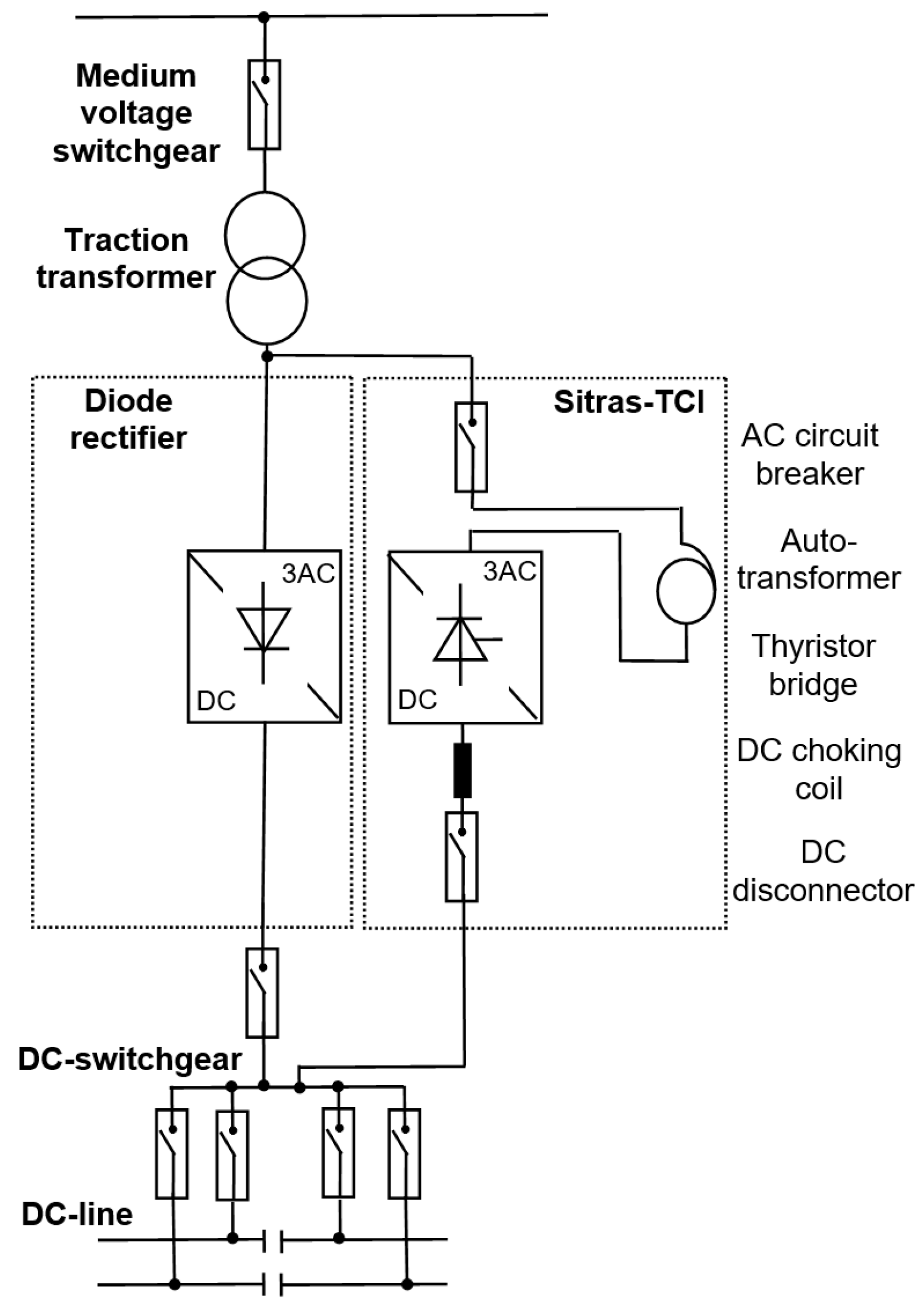
- diode rectifier and thyristor-based inverter, also referred as thyristor line commutated inverter (TCI);
- -
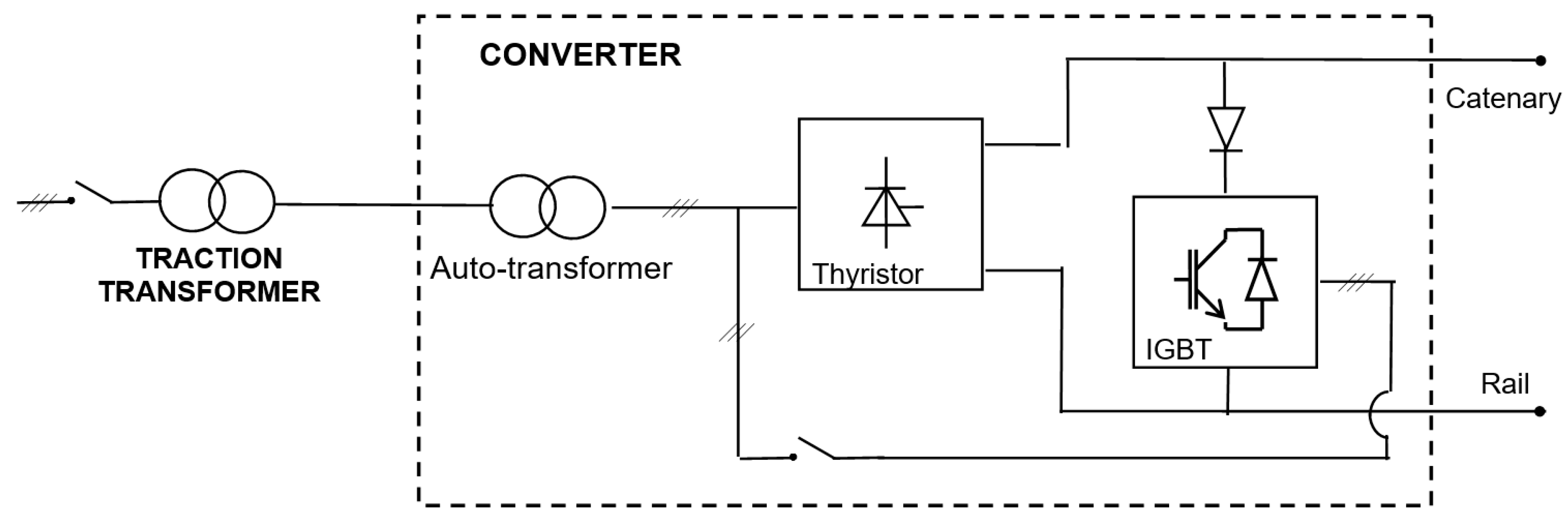
- diode rectifier and pulse-width modulation (PWM) inverter based on fully controlled switches.
4.1. Reversible Substations with Diode Rectifier and Thyristor-Based Inverter
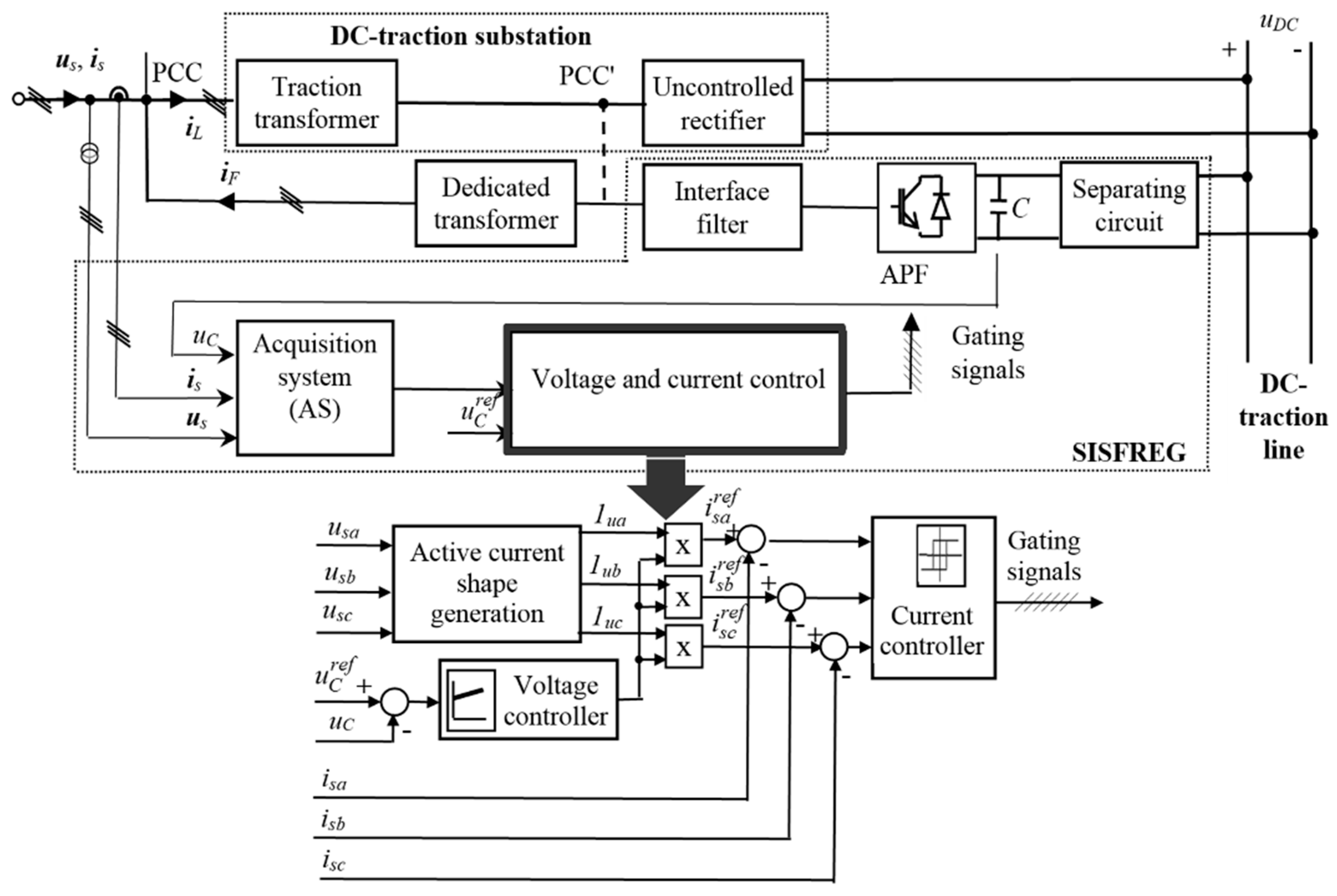
4.2. Reversible Substations with Diode Rectifier and PWM Inverter
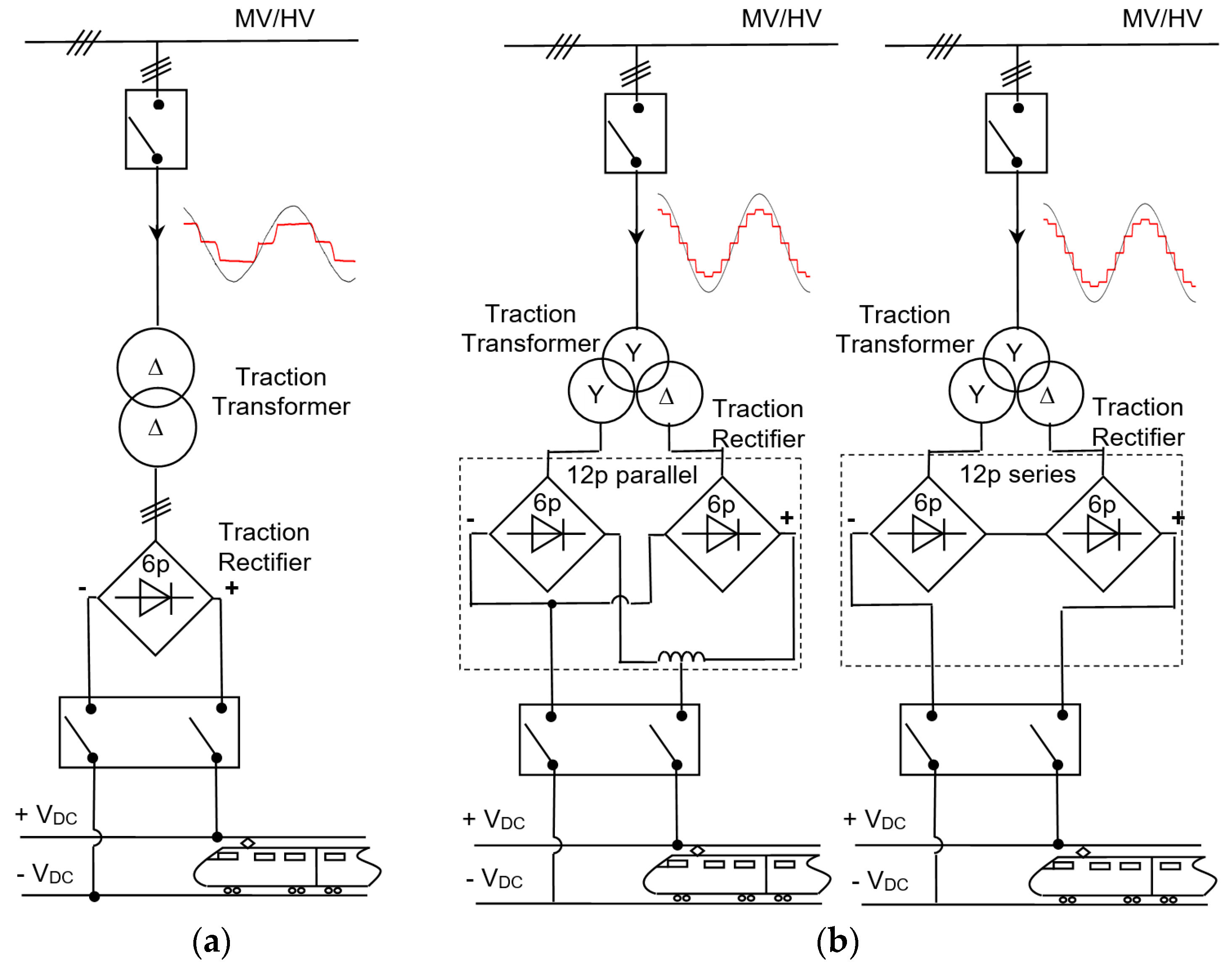
- -
- for the three-phase bridge rectifier and for the 12-pulse parallel rectifier.
- -
- for the 12-pulse series rectifier.
- -
- kp = 0.87 for the three-phase bridge rectifier and for the 12-pulse parallel rectifier.
- -
- kp = 1.74 for the 12-pulse series rectifier.
4.2.1. The INGEBER Solution
4.2.2. The Enviline ERS Solution
4.2.3. Other Implementations of the Reversible Substations with Diode Rectifier and PWM Inverter
4.3. Reversible Substations with Reversible Thyristor Controlled Rectifiers
4.4. Reversible Substations with Thyristor-Based Rectifier and PWM Inverter
4.5. Reversible Substations with a Single Rectifier/Inverter Converter
- -
- Sydney Light Rail, Australia, where 13 Hesop (9 Hesop 750V 1.2MW and 4 Hesop 750 V 2 MW) are being tested;
- -
- Panama City metro line, where 8 Hesop 1500 V 4 MW are being implemented;
- -
- Riyadh metro lines, Saudi Arabia, where 70 Hesop 750 V 1.2 MW are being installed; and
- -
- metro lines in Dubai, where 15 Hesop 750 V 2 MW are being implemented for enhancement and extension.
5. New Trends in Increasing the Energy Efficiency
6. Conclusions
Author Contributions
Funding
Conflicts of Interest
References
- Hill, R.J. Electric railway traction. Part 3 Traction power supplies. Power Eng. J. 1994, 8, 275–286. [Google Scholar] [CrossRef]
- Aeberhard, M.; Courtois, C.; Ladoux, P. Railway traction power supply from the state of the art to future trends. In Proceedings of the 20th International Symposium on Power Electronics, Electrical Drives, Automation and Motion, Pisa, Italy, 14–16 June 2010; pp. 1350–1355. [Google Scholar] [CrossRef]
- Bałkowiec, T.; Koczara, W. Three-phase rectifier dedicated to DC traction substation. Prz. Elektrotech. 2017, 9, 41–45. [Google Scholar] [CrossRef]
- ABB. ABB Traction Rectifiers Diode Rectifiers for DC Traction Substations. Available online: https://library.e.abb.com/public/2c94715f41cc5e11c12577a0004872b6/ABB%20traction%20rectifiers_4128PL219-W2-en_09-2010.pdf (accessed on 8 February 2019).
- Mayet, C.; Delarue, P.; Bouscayrol, A.; Chattot, E.; Verhille, J.N. Dynamic model and causal description of a traction power substation based on 6-pulse diode rectifier. In Proceedings of the IEEE Vehicle Power and Propulsion Conference, Coimbra, Portugal, 27–30 October 2014; pp. 1–6. [Google Scholar] [CrossRef]
- Popescu, M.; Bitoleanu, A.; Deaconu, I.; Dobriceanu, M. Improvement of power quality and energy efficiency in Bucharest metro traction substations. In Proceedings of the Power Electronics and Motion Control (PEMC 2016), Varna, Bulgaria, 25–30 September 2016; pp. 898–903. [Google Scholar] [CrossRef]
- Vilberger, M.E.; Kulekina, A.V.; Bakholdin, P.A. The twelfth-pulse rectifier for traction substations of electric transport. IOP Conf. Ser. Earth Environ. Sci. 2017, 87, 1–5. [Google Scholar] [CrossRef]
- Brociek, W.; Wilanowicz, R.; Filipowicz, S. Cooperation of 12-pulse converter with a power system in dynamic state. Prz. Elektrotech. 2014, 5, 67–70. [Google Scholar]
- Bae, C.H.; Han, M.S.; Kim, Y.K.; Choi, C.Y. Simulation study of regenerative inverter for DC traction substation. In Proceedings of the International Conference on Electrical Machines and Systems, Nanjing, China, 27–29 September 2005; pp. 1452–1456. [Google Scholar] [CrossRef]
- de Jager, W.A.G. Buddy bidirectional supply for traction substations. In Proceedings of the 14th European Conference on Power Electronics and Applications (EPE 2011), Birmingham, UK, 30 August–1 September 2011. [Google Scholar]
- Sikora, A.; Kulesz, B. Effectiveness of different designs of 12- and 24-pulse rectifier transformers. In Proceedings of the 18th International Conference on Electrical Machines (ICEM 2008), Vilamoura, Portugal, 6–9 September 2008. [Google Scholar] [CrossRef]
- Sikora, A.; Kulesz, B. Properties of novel traction polyphase rectifier transformer. In Proceedings of the XXth International Conference on Electrical Machines, Marseille, France, 2–5 September 2012. [Google Scholar] [CrossRef]
- Zhang, G.; Qian, J.; Zhang, X. Application of a high-power reversible converter in a hybrid traction power supply system. Appl. Sci. 2017. [Google Scholar] [CrossRef]
- Gelman, V. Energy savings with reversible thyristor controlled rectifier. In Proceedings of the 2009 ASME Joint Rail Conference (JRC 2009), Pueblo, CO, USA, 3−5 March 2009; pp. 41–46. [Google Scholar] [CrossRef]
- Gelman, V. Thyristor controlled rectifiers (TCR) for traction—Problems and solutions. In Proceedings of the 3rd International Conference on Electric Power and Energy Conversion Systems, Istanbul, Turkey, 2–4 October 2013. [Google Scholar] [CrossRef]
- Sagareli, S.; Gelman, V. Implementation of new technologies in traction power systems. In Proceedings of the ASME/IEEE Joint Rail Conference, Baltimore, MD, USA, 6–8 April 2004. [Google Scholar] [CrossRef]
- Gelman, V. Insulated-gate bipolar transistor rectifiers: Why they are not used in traction power substations. IEEE Veh. Technol. Mag. 2014, 9, 86–93. [Google Scholar] [CrossRef]
- Wang, L.; Zhang, G.; Shen, M.; Quan, H.; Liu, Z. A novel traction supply system for urban rail transportation with bidirectional power flow and based on PWM rectifier. In Proceedings of the International Conference on Energy and Environment Technology, Guilin, China, 16–18 October 2009; pp. 40–43. [Google Scholar] [CrossRef]
- IEEE Recommended Practice and Requirements for Harmonic Control in Electrical Power Systems; IEEE Std. 519-2014 (Revision of IEEE Std. 519-1992); IEEE: Piscataway, NJ, USA, 2014; pp. 1–29.
- Gazafrudi, S.; Langerudy, A.; Fuchs, E.; Al-Haddad, K. Power quality issues in railway electrification: A comprehensive perspective. IEEE Trans. Ind. Electron. 2015, 62, 3081–3090. [Google Scholar] [CrossRef]
- Gunavardhini, N.; Chandrasekaran, M. Power quality conditioners for railway traction—A review. Autom. J. Control Meas. Electron. Comput. Commun. 2016, 57, 150–162. [Google Scholar] [CrossRef]
- Lao, K.W.; Wong, M.C.; Santoso, S. Recent advances of FACTS devices for power quality compensation in railway traction power supply. In Proceedings of the IEEE Power Engineering Society Transmission and Distribution Conference, Denver, CO, USA, 16–19 April 2018. [Google Scholar] [CrossRef]
- Grasselli, U.; Lamedica, R.; La Vitola, A.; Maranzano, G.; Prudenzi, A. Characterization of PQ indices for an electrified metro-transit system through simulation and monitoring activities. In Proceedings of the Power Engineering Society Summer Meeting, Vancouver, BC, Canada, 15–19 July 2001; pp. 210–215. [Google Scholar] [CrossRef]
- Psomopoulos, C.S.; Ioannidis, G.C.; Kaminaris, S.D.; Angeladas, E.P.; Tsiolis, S.; Villiotis, I. Experimental and theoretical investigation of the harmonic distortion in the 600V urban railways system of Athens. In Proceedings of the 6th IET Conference on Railway Condition Monitoring (RCM 2014), Birmingham, UK, 17–18 September 2014. [Google Scholar] [CrossRef]
- Djeghader, Y.; Zellouma, L.; Labar, U.; Toufouti, R.; Chelli, Z. Study and filtering of harmonics in a dc electrified railway system. In Proceedings of the 7th international conference on modelling, identification and control (ICMIC-2015), Sousse, Tunisia, 18–20 December 2015. [Google Scholar] [CrossRef]
- Djeghader, Y.; Zellouma, L. Filtering of harmonics in dc traction substation system. J. Electr. Eng. 2017, 7, 29–35. [Google Scholar]
- Rekha, T.; Bisharathu Beevi, A. Power quality control in DC traction systems using static var compensator and harmonic filter. IJERT 2014, 3, 733–740. [Google Scholar]
- Ramos, G.; Cantor, E.; Rios, M.A.; Roa, L.F. Instantaneous p-q theory for harmonic compensation with active power filter in dc traction systems. In Proceedings of the International Conference on Power Engineering, Energy and Electrical Drives, Malaga, Spain, 11–13 May 2011. [Google Scholar] [CrossRef]
- Hosseini, S.H.; Shahnia, F.; Sarhangzadeh, M.; Babaei, E. Power quality improvement of DC electrified railway distribution systems using hybrid filters. In Proceedings of the International Conference on Electrical Machines and Systems, Nanjing, China, 27–29 September 2005; pp. 1273–1277. [Google Scholar] [CrossRef]
- Koseki, T. Technologies for saving energy in railway operation: General discussion on energy issues concerning railway technology. IEEJ Trans. Electr. Electron. Eng. 2010, 5, 285–290. [Google Scholar] [CrossRef]
- González-Gil, A.; Palacin, R.; Batty, P. Sustainable urban rail systems: Strategies and technologies for optimal management of regenerative braking energy. Energy Convers. Manag. 2013, 75, 374–388. [Google Scholar] [CrossRef]
- González-Gil, A.; Palacin, R.; Batty, P.; Powell, J.P. A systems approach to reduce urban rail energy consumption. Energy Convers. Manag. 2014, 80, 509–524. [Google Scholar] [CrossRef]
- González-Gil, A.; Palacin, R.; Batty, P.; Powell, J.P. Energy-efficient urban rail systems: Strategies for an optimal management of regenerative braking energy. In Proceedings of the Transport Research Arena, Paris, France, 14–17 April 2014; pp. 374–388. [Google Scholar]
- López-López, Á.J.; Pecharromán, R.R.; Fernández-Cardador, A.; Cucala, A.P. Assessment of energy-saving techniques in direct-current-electrified mass transit systems. Transp. Res. Part C Emerg. Technol. 2014, 38, 85–100. [Google Scholar] [CrossRef]
- Yang, X.; Li, X.; Ning, B.; Tang, T. A survey on energy-efficient train operation for urban rail transit. IEEE Trans. Intell. Transp. Syst. 2016, 17, 2–13. [Google Scholar] [CrossRef]
- Kampeerawar, W.; Koseki, T.; Zhou, F. Efficient urban railway design integrating train scheduling, onboard energy storage, and traction power management. In Proceedings of the International Power Electronics Conference (IPEC-Niigata 2018-ECCE Asia), Niigata, Japan, 20–24 May 2018; pp. 3257–3264. [Google Scholar] [CrossRef]
- Zhao, N.; Roberts, C.; Hillmansen, S.; Tian, Z.; Weston, P.; Chen, L. An integrated metro operation optimization to minimize energy consumption. Transp. Res. Part C Emerg. Technol. 2017, 75, 168–3182. [Google Scholar] [CrossRef]
- Xu, H.Z.; Cheng, G.Z.; Wu, C. Study on the design method of energy-saving slope in subway. Appl. Mech. Mater. 2012, 204–208, 1559–1564. [Google Scholar] [CrossRef]
- Su, S.; Tang, T.; Wang, Y. Evaluation of strategies to reducing traction energy consumption of metro systems using an optimal train control simulation model. Energies 2016, 9, 105. [Google Scholar] [CrossRef]
- Ghavihaa, N.; Campilloa, J.; Bohlinb, M.; Dahlquista, E. Review of application of energy storage devices in railway transportation. Energy Procedia 2017, 105, 4561–4568. [Google Scholar] [CrossRef]
- Hayashiya, H.; Iino, Y.; Takahashi, H.; Kawahara, K.; Yamanoi, T.; Sekiguchi, T.; Sakaguchi, H.; Sumiya, A.; Kon, S. Review of regenerative energy utilization in traction power supply system in Japan: Applications of energy storage systems in d.c. traction power supply system. In Proceedings of the 43rd Annual Conference of the IEEE Industrial Electronics Society (IECON 2017), Beijing, China, 29 October–1 November 2017; pp. 3918–3923. [Google Scholar] [CrossRef]
- Ceraolo, M.; Lutzemberger, G.; Meli, E.; Pugi, L.; Rindi, A.; Pancari, G. Energy storage systems to exploit regenerative braking in DC railway systems: Different approaches to improve efficiency of modern high speed trains. J. Energy Storage 2018, 16, 269–279. [Google Scholar] [CrossRef]
- Standard IEC 62924:2017 Railway Applications—Fixed Installations—Stationary Energy Storage System for DC Traction Systems. Available online: https://www.sis.se/api/document/preview/8024733/ (accessed on 8 February 2019).
- Jang, S.J.; Choi, C.Y.; Bae, C.H.; Song, S.H.; Won, C.Y. Study of regeneration power control inverter for DC traction with active power filter ability. In Proceedings of the 31st Annual Conference of IEEE (IECON 2005), Raleigh, NC, USA, 6–10 November 2005. [Google Scholar] [CrossRef]
- Henning, P.H.; Fuchs, H.D.; Roux, A.D.L.; Mouton, H.A.T. A 1.5-MW seven-cell series-stacked converter as an active power filter and regeneration converter for a DC traction substation. IEEE Trans. Power Electron. 2008, 23, 2230–2236. [Google Scholar] [CrossRef]
- de Jager, W.A.G.; Huizer, M.; van der Pols, E.K.H. Implementation of an active regeneration unit in a traction substation. In Proceedings of the 16th European Conference on Power Electronics and Applications, Lappeenranta, Finland, 26–28 August 2014. [Google Scholar] [CrossRef]
- Romo, A. Reversible Substation in Heavy Rail. In Proceedings of the Energy Recovery Workshop, Madrid, Spain; 2015. Available online: https://docplayer.net/50090204-Reversible-substation-in-heavy-rail.html (accessed on 6 February 2019).
- Gray, A.J.; Stinton, D. Designing reversible substations using inverters. In Proceedings of the 7th IET Professional Development Course on Railway Electrification Infrastructure and Systems (REIS 2015), London, UK, 8–11 June 2015. [Google Scholar] [CrossRef]
- Jefimowski, W.; Szeląg, A. The multi-criteria optimization method for implementation of a regenerative inverter in a 3kV DC traction system. Electr. Power Syst. Res. 2018, 161, 61–73. [Google Scholar] [CrossRef]
- Khodaparastan, M.; Brandauer, W.; Mohamed, A. Recuperation of regenerative braking energy in electric rail transit systems. IEEE Trans. Intell. Transp. Syst. 2019, 1–17. [Google Scholar] [CrossRef]
- Konishi, T.; Morimoto, H.; Aihara, T.; Tsutakawa, M. Fixed energy storage technology applied for DC electrified railway. IEEJ Trans. 2010, 5, 270–277. [Google Scholar] [CrossRef]
- Takagi, R. Energy saving techniques for the power feeding network of electric railways. IEEJ Trans. 2010, 5, 312–316. [Google Scholar] [CrossRef]
- Kondo, K. Recent energy saving technologies on railway traction systems. IEEJ Trans. 2010, 5, 298–303. [Google Scholar] [CrossRef]
- UIC, Energy Efficiency Technologies for Railways. Available online: http://www.railway-energy.org (accessed on 1 February 2019).
- Dol, L.G.; de Bernardinis, A. AC or DC grid for railway stations? In Proceedings of the International Exhibition and Conference for Power Electronics, Intelligent Motion, Renewable Energy and Energy Management, Nuremberg, Germany, 10–12 May 2016. [Google Scholar]
- Siad, S.; Damm, G.; Dol, L.G.; de Bernardinis, A. Design and control of a DC grid for railway stations. In Proceedings of the International Exhibition and Conference for Power Electronics, Intelligent Motion, Renewable Energy and Energy Management, Nuremberg, Germany, 16–18 May 2017. [Google Scholar]
- Dol, L.G.; De Bernardinis, A.; Nassiopoulos, A.; Peny, A.; Bourquin, F. On the use of train braking energy regarding the electrical consumption optimization in railway station. Transp. Res. Procedia 2016, 14, 655–664. [Google Scholar] [CrossRef]
- Guillaumin, B. A Global View on OSIRIS. In Proceedings of the OSIRIS Final Conference, Brussels, Belgium, 31 March 2015; Available online: http://www.osirisrail.eu/wp-content/uploads/2015/05/01_-_A_global_view_on_OSIRIS.pdf (accessed on 1 February 2019).
- Goikoetxea, J.; Reynaud, J.F. New Concept of Onboard Energy Storage System for Tram Tested in Vitoria-Gasteiz. In Proceedings of the OSIRIS Final Conference, Brussels, 31 March 2015; Available online: http://www.osirisrail.eu/wp-content/uploads/2015/05/03_-_New_concept_of_Onboard_Energy_Storage_System_for_tram_tested_in_Vitoria-Gasteiz.pdf (accessed on 1 February 2019).
- Parisi, M.; Cardarelli, F. Innovative Auxiliary Converter for Metro Trains Installed in Milan. In Proceedings of the OSIRIS Final Conference, Brussels, 31 March 2015; Available online: http://www.osirisrail.eu/wp-content/uploads/2015/05/04_-_Innovative_auxiliary_converter_for_metro_trains_installed_in_Milan.pdf (accessed on 1 February 2019).
- Devaux, F.O.; Tackoen, X. WP2B Energy Recovery. Overview of Braking Energy Recovery Technologies in the Public Transport Field. Ticket to Kyoto Report, March 2011. Available online: https://www.tickettokyoto.eu/sites/default/files/downloads/T2K_ER_overview_technologies_web.pdf (accessed on 1 February 2019).
- Devaux, F.O.; Tackoen, X. WP2B Energy Recovery. Guidelines for Braking Energy Recovery Systems in Urban Rail Networks, Ticket to Kyoto Final Report, September 2014. Available online: https://www.tickettokyoto.eu/sites/default/files/downloads/T2K_WP2B_Energy%20Recovery_Final%20Report_2.pdf (accessed on 1 February 2019).
- ABB White Paper, SEPTA’s Wayside Energy Storage Project. 2014. Available online: http://docplayer.net/35465351-Septa-s-southeastern-pennsylvania-transit-authority-wayside-energy-storage-project.html (accessed on 1 February 2019).
- ABB Communications, Reducing Rail Energy Use by 10 Percent. Available online: http://www.abb.com/cawp/seitp202/84e9f73743b3b3f8c1257a39004aab33.aspx (accessed on 1 February 2019).
- ABB Communications, SEPTA Stays Focused on Energy Efficiency with Second Energy Storage and Unique Hybrid System from ABB. Available online: http://www.abb.com/cawp/seitp202/186379817a2df9b6c1257d57004c026e.aspx (accessed on 1 February 2019).
- Réchard, G.; Gouttefangeas, R. Recovering energy from train braking for traction and grid use. Energy Procedia 2017, 143, 61–66. [Google Scholar] [CrossRef]
- Martinez, J.; Ramos, G. Reactive power and harmonic distortion control in electric traction systems. In Proceedings of the IEEE/PES Transmission and Distribution Conference and Exposition: Latin America, Sao Paulo, Brazil, 8–10 November 2010; pp. 190–195. [Google Scholar] [CrossRef]
- Popescu, M.; Bitoleanu, A.; Preda, A. Performance of an active DC-Traction substation with 12-pulse parallel rectifier and indirect current control. Ann. Univ. Craiova Electr. Eng. Ser. 2015, 39, 73–79. [Google Scholar]
- Blooming, T.M.; Carnovale, D.J. Application of IEEE STD 519-1992 harmonic limits. In Proceedings of the Conference Record of 2006 Annual Pulp and Paper Industry Technical Conference, Appleton, WI, USA, 18–23 June 2006. [Google Scholar] [CrossRef]
- IEEE Recommended Practice for Electric Power Distribution for Industrial Plants; IEEE Std. 141-1993; IEEE: Piscataway, NJ, USA, 1993.
- Akagi, H.; Kanazawa, Y.; Nabae, A. Instantaneous reactive power compensators comprising switching devices without energy storage components. IEEE Trans. Ind. Appl. 1984, IA-20, 625–630. [Google Scholar] [CrossRef]
- Popescu, M.; Bitoleanu, A.; Suru, V. A DSP-based implementation of the p-q theory in active power filtering under nonideal voltage conditions. IEEE Trans. Ind. Inform. 2013, 9, 880–889. [Google Scholar] [CrossRef]
- Popescu, M.; Bitoleanu, A. Simulink library for reference current generation in active DC traction substations. Int. J. Electr. Comput. Energ. Electron. Commun. Eng. 2015, 9, 578–585. [Google Scholar]
- Popescu, M.; Bitoleanu, A.; Suru, V.; Dobriceanu, M. Increasing power quality in a 6-pulse DC-traction substation. In Proceedings of the 11-th International Conference on Electromechanical and Power Systems, Chisinau, Moldova, 12–13 October 2017; pp. 483–488. [Google Scholar] [CrossRef]
- Popescu, M.; Bitoleanu, A.; Suru, V.; Dobriceanu, M. DC-Traction substation with improved power quality and regeneration capability. Ann. Univ. Craiova Electr. Eng. Ser. 2017, 41, 22–28. [Google Scholar]
- Arboleya, P.; Bidaguren, P.; Armendariz, U. Energy is on board: Energy storage and other alternatives in modern light railways. IEEE Electrific. Mag. 2016, 4, 30–41. [Google Scholar] [CrossRef]
- National Academies of Sciences, Engineering, and Medicine. Guiding the Selection and Application of Wayside Energy Storage Technologies for Rail Transit and Electric Utilities; The National Academies Press: Washington, DC, USA, 2010. [Google Scholar]
- Ceraolo, M.; Lutzemberger, G. Stationary and on-board storage systems to enhance energy and cost efficiency of tramways. J. Power Sources 2014, 128–139. [Google Scholar] [CrossRef]
- Meinert, M. New mobile energy storage system for rolling stock. In Proceedings of the 13th European Conference on Power Electronics and Applications, Barcelona, Spain, 8–10 September 2009. [Google Scholar]
- Steiner, M.; Klohr, M.; Pagiela, S. Energy storage system with ultracaps on board of railway vehicles. In Proceedings of the Power Electronics and Applications, Aalborg, Denmark, 2–5 September 2007; pp. 1–10. [Google Scholar] [CrossRef]
- Ogasa, M. Application of energy storage technologies for electric railway vehicles-examples with hybrid electric railway vehicles. IEEJ Trans. Electr. Electron. Eng. 2010, 5. [Google Scholar] [CrossRef]
- Lacôte, F. Alstom—Future trends in railway transportation. Jpn. Railw. Transp. Rev. 2005, 42, 4–9. [Google Scholar]
- Iannuzzi, D.; Pagano, E.; Tricoli, P. The use of energy storage systems for supporting the voltage needs of urban and suburban railway contact lines. Energies 2013, 6, 1802–1820. [Google Scholar] [CrossRef]
- Shimada, M.; Oishi, R.; Araki, D.; Nakamura, Y. Energy storage system for effective use of regenerative energy in electrified railways. Hitachi Rev. 2010, 59, 33–38. [Google Scholar]
- Mohamed, A.; Reid, A.; Lamb, T. White Paper on Wayside Energy Storage for Regenerative Braking Energy Recuperation in the Electric Rail System; Con Edison: New York, NY, USA, 2018; pp. 1–20. [Google Scholar]
- Ogura, K.; Nishimura, K.; Matsumura, T.; Tonda, C.; Yoshiyama, E.; Andriani, M.; Francis, W.; Schmitt, R.A.; Visgotis, A.; Gianfrancesco, N. Test results of a high capacity wayside energy storage system using Ni-MH batteries for DC electric railway at New York City Transit. In Proceedings of the IEEE Green Technologies Conference, Baton Rouge, LA, USA, 14–15 April 2011. [Google Scholar] [CrossRef]
- Richardson, M.B. Flywheel energy storage system for traction applications. In Proceedings of the IEEE International Conference on Power Electronics, Machines and Drives, Bath, UK, 4–7 June 2002. [Google Scholar] [CrossRef]
- Kubin, J.; Richter, A. Efficiency of mechanical energy recovery from a tram by different input conditions. In Proceedings of the 15th International Power Electronics and Motion Control Conference, Novi Sad, Serbia, 4–6 September 2012. [Google Scholar] [CrossRef]
- Saleh, M.; Dutta, O.; Esa, Y.; Mohamed, A. Quantitative analysis of regenerative energy in electric rail traction systems. In Proceedings of the Industry Applications Society Annual Meeting, Cincinnati, OH, USA, 1–5 October 2017; pp. 1–7. [Google Scholar] [CrossRef]
- Gelman, V. Energy storage that may be too good to be true: Comparison between wayside storage and reversible thyristor controlled rectifiers for heavy rail. IEEE Veh. Technol. Mag. 2013, 8, 70–80. [Google Scholar] [CrossRef]
- Cornic, D. Efficient recovery of braking energy through a reversible dc substation. In Proceedings of the Electrical Systems for Aircraft, Railway and Ship Propulsion (ESARS) Conference, Bologna, Italy, 19–21 October 2010; pp. 1–9. [Google Scholar] [CrossRef]
- ALSTOM. RE-USE Layman’s Report September 2012–May 2018. Available online: https://www.alstom.com/sites/alstom.com/files/2018/10/30/re-use_laymans_report_en.pdf (accessed on 9 February 2019).
- Siemens, AG. Sitras TCI–Thyristor Controlled Inverter for DC Traction Power Supply. Available online: https://w3.usa.siemens.com/mobility/us/documents/en/rail-solutions/railway-electrification/dc-traction-power-supply/sitras-tci-en.pdf (accessed on 9 February 2019).
- Popescu, M.; Bitoleanu, A.; Suru, V.; Preda, A. System for converting the dc traction substations into active substations. In Proceedings of the 9th International Symposium on Advanced Topics in Electrical Engineering, Bucharest, Romania, 6–9 May 2015; pp. 632–637. [Google Scholar] [CrossRef]
- Bitoleanu, A.; Popescu, M. Active Power Filters; Universitaria: Craiova, Romania, 2010. (In Romanian) [Google Scholar]
- Ibaiondo, H.; Romo, A. Kinetic energy recovery on railway systems with feedback to the grid. In Proceedings of the 14th International Power Electronics and Motion Control Conference, Ohrid, Macedonia, 6–8 September 2010; pp. T9-94–T9-97. [Google Scholar] [CrossRef]
- Popescu, M.; Bitoleanu, A.; Dobriceanu, M. FBD-based control in active DC-traction substations. In Proceedings of the 13th International Conference on Applied and Theoretical Electricity, Craiova, Romania, 6–8 October 2016. [Google Scholar] [CrossRef]
- Ortega, J.M.; Ibaiondo, H.; Romo, A. Kinetic energy recovery on railway systems with feedback to the grid. In Proceedings of the 9th World Congress on Railway Research, Lille, France, 22–26 May 2011. [Google Scholar]
- Ortega, J.M. Ingeber System for Kinetic Energy Recovery & Metro Bilbao Experience. I Rail Techn. Forum Internat, Madrid, 28 June 2011. Available online: https://www.vialibre-ffe.com/pdf/Estaciones_reversibles.pdf (accessed on 31 January 2019).
- ABB. Enviline ERS–Energy Recuperation System for DC Rail Transportation. Available online: https://library.e.abb.com/public/f6b1e73d49874bb19d9c504bb7798065/ENVILINE%20ERS%20EN.pdf (accessed on 2 February 2019).
- Song, S.H.; Jang, S.J.; Bang, H.J.; Won, C.Y. Regeneration inverter system for DC traction with harmonic reduction capability. In Proceedings of the 30th Annual Conference of IEEE Industrial Electronics Society, Busan, Korea, 2–6 November 2004; pp. 1463–1468. [Google Scholar] [CrossRef]
- Kouassi, N.; Navarro, N.; Letrouvé, T.; Caron, H.; Saudemont, C.; Francois, B.; Robyns, B. Dynamic modelling of braking energy recovered using a bi-directional power station on DC railway electrical network. In Proceedings of the 18th International Power Electronics and Motion Control Conference, Budapest, Hungary, 26–30 August 2018; pp. 109–114. [Google Scholar] [CrossRef]
- Popescu, M.; Bitoleanu, A.; Dobriceanu, M. Configuring and performances of reversible DC-traction substations with compensation capabilities. Bull. Polytech. Inst. Iasi 2018, 64, 19–33. [Google Scholar]
- Popescu, M.; Bitoleanu, A.; Preda, A. A new design method of an LCL filter applied in active DC-traction substations. IEEE Trans. Ind. Appl. 2018, 54, 3497–3507. [Google Scholar] [CrossRef]
- Popescu, M.; Bitoleanu, A.; Dobriceanu, M.; Teodorescu, F.A. On the AC-connecting of a system for active filtering and regeneration in active DC-traction substations. In Proceedings of the 14th International Conference on Applied and Theoretical Electricity, Craiova, Romania, 4–6 October 2018. [Google Scholar] [CrossRef]
- Popescu, M.; Bitoleanu, A.; Preda, A. Design and performances of the separating circuit in regeneration and filtering system for active DC-traction substations. In Proceedings of the International Symposium on Power Electronics, Electrical Drives, Automation and Motion, Anacapri, Italy, 22–24 June 2016; pp. 1180–1185. [Google Scholar] [CrossRef]
- Popescu, M.; Bitoleanu, A.; Preda, A. p-q Theory based control in active DC-traction substation with 12-pulse parallel rectifier. In Proceedings of the 10th International Conference on Electromechanical and Power Systems, Chisinau, Moldova, 6–9 October 2015; pp. 471–476. [Google Scholar]
- Suru, V.; Popescu, M.; Preda, A. Using the CPC theory for a filtering and energy recovery system used in urban traction DC substations. Acta Electroteh. 2016, 57, 484–489. [Google Scholar]
- Popescu, M.; Bitoleanu, A.; Suru, V. Indirect current control in active DC railway traction substations. In Proceedings of the ACEMP-OPTIM-ELECTROMOTION Joint Conference, Side, Turkey, 2–4 September 2015; pp. 192–197. [Google Scholar] [CrossRef]
- Bitoleanu, A.; Popescu, M.; Suru, C.V. Theoretical and experimental evaluation of the indirect current control in active filtering and regeneration systems. In Proceedings of the 2017 International Conference on Optimization of Electrical and Electronic Equipment (OPTIM) & 2017 International Aegean Conference on Electrical Machines and Power Electronics (ACEMP), Brasov, Romania, 23–25 May 2017; pp. 759–764. [Google Scholar] [CrossRef]
- Bitoleanu, A.; Popescu, M.; Suru, C.V. Configuring and experimental evaluation of a laboratory model for filtering and regeneration in active DC traction substations. In Proceedings of the 10th International Symposium on Advanced Topics in Electrical Engineering (ATEE 2017), Bucharest, Romania, 23–25 March 2017; pp. 591–596. [Google Scholar] [CrossRef]
- Bitoleanu, A.; Popescu, M.; Suru, C.V. Bidirectional static system for active D.C. traction substations. Theoretical and experimental evaluation. In Proceedings of the 5th International Symposium on Electrical and Electronics Engineering, Galati, Romania, 20–22 October 2017. [Google Scholar] [CrossRef]
- ABB. ENVILINE TCR Traction Controlled Rectifiers for DC Rail Transportation. Available online: https://search-ext.abb.com/library/Download.aspx?DocumentID=4116PL839-W2-en.&LanguageCode=en&DocumentPartId=&Action=Launch (accessed on 9 February 2019).
- Kim, S.A.; Han, S.-W.; Han, G.-J.; Cho, Y.-H. Initial firing angle control of 12-pulse parallel connected thyristor dual converter for urban railway power substations. In Proceedings of the 2016 International Symposium on Power Electronics, Electrical Drives, Automation and Motion (SPEEDAM), Anacapri, Italy, 22–24 June 2016. [Google Scholar] [CrossRef]
- Pejovic, P.; Kolar, J.W.; Nishida, Y. Bidirectional AC-DC converter for regenerative braking. Electronics 2012, 16, 3–8. [Google Scholar] [CrossRef]
- Cornic, D.; Lechelle, S. Best of Reversible Direct Current Sub-Station. In Proceedings of the Railenergy Final Conference, Brussels, Belgium, 25 November 2010; Available online: https://www.scribd.com/document/62319870/6-Best-of-8220-Reversible-Direct-Current-Sub-Station-8221 (accessed on 3 February 2019).
- Warin, Y.; Lanselle, R.; Thiounn, M. Active substation. In Proceedings of the 9th World Congress on Railway Research (WCRR 2011), Lille, France, 22–26 May 2011. [Google Scholar]
- HESOP Energy Saver London Underground-Case Study. Available online: https://manualzz.com/doc/8612858/hesop-london-underground---case-study (accessed on 10 February 2019).
- Fazel, S.S.; Firouzian, S.; Shandiz, B.K. Energy-efficient emplacement of reversible DC traction power substations in urban rail transport through regenerative energy recovery. Int. J. Railw. Res. 2016, 1, 11–22. [Google Scholar]
- Hayashiya, H.; Yoshizumi, H.; Suzuki, T.; Furukawa, T.; Kondoh, T.; Kitano, M.; Aoki, T.; Ishii, T.; Kurosawa, N.; Miyagawa, T. Necessity and possibility of smart grid technology application on railway power supply system. In Proceedings of the 14th International Conference on Power Electronics and Applications, Birmingham, UK, 30 August–1 September 2011; pp. 1–10. [Google Scholar]
- Wang, W.; Wu, M.; Li, Q.; Chen, W. Method for improving power quality of metro traction power supply system with PV integration. In Proceedings of the 2017 Chinese Automation Congress (CAC), Jinan, China, 20–22 October 2017; pp. 1682–1685. [Google Scholar] [CrossRef]
- Hayashiya, H. Recent trend of regenerative energy utilization in traction power supply system in Japan. Urban Rail Transit 2017, 3, 183–191. [Google Scholar] [CrossRef]
- Zhang, G.; Tian, Z.; Du, H.; Liu, Z. A novel hybrid DC traction power supply system integrating PV and reversible converters. Energies 2018, 11, 1661. [Google Scholar] [CrossRef]


| Technology | Provider, Commercial Product | Applications | References |
|---|---|---|---|
| Supercapacitor | Bombardier, MITRAC Energy Saver | Light rail, Mannheim (Germany), 750 V, 2003 | [33,40,50,61,80,81] |
| Supercapacitor | Siemens, Sitras MES | Tram in Innsbruck (Austria) | [31,33,61] |
| Supercapacitor | CAF, ACR system | Tram in Seville, Saragossa, Granada (Spain) | [33,61] |
| Supercapacitor | Alstom, STEEM | Tram in Paris (France), 2009 | [31,33,61] |
| Li-ion | Kinki Shayro, LFX-300, streetcar | Charlotte (North Carolina USA), 2010 | [31,33,61] |
| Ni-MH | Alstom – Saft | Tram in Nice (France), 2007 | [31,50] |
| Flywheel | Alstom & CCM, Citadis | Tram in Rotterdam (Rotterdam), 2004 | [33,82] |
| Hybrid Supercapacitor + Ni-MH | Siemens, Sitras HES | Light rail, Lisbon (Portugal), 750 V DC, 2008 | [33,61,79] |
| Technology | Provider, Commercial Product | Applications | References |
|---|---|---|---|
| Supercapacitor | Siemens, Sitras SES | Bochum, Cologne and Dresden (Germany), Madrid (Spain), Beijing (China), 600V, 750V | [33,61] |
| Supercapacitor | Envitech Energy (ABB group), Envistore | Warsaw (Poland), Philadelphia (Pennsylvania) | [31,64] |
| Supercapacitor | Meiden, Capapost | Hong Kong | [31] |
| Li-ion | Hitachi, B-CHOP | Kobe (Japan) | [31,84] |
| Li-ion | Saft, Intensium Max | Philadelphia (Pennsylvania) | [31,85] |
| Ni-MH | Kawasak, Gigacell BPS | New York City (USA) | [31,86] |
| Flywheel | Kinetic Traction Systems, GTR system | London (UK), New York (USA), Lyon (France) | [31,87] |
| Flywheel | Vycon, Regen system | Los Angeles (California) | [31,50] |
| Commercial Product | Provider | Applications | References |
|---|---|---|---|
| HESOP | Alstom |
| [31,33,48,50,91,92,116,118] |
| Sitras-TCI | Siemens |
| [31,33,50,61,90,93] |
| INGEBER | INGETEAM Traction |
| [33,47,50,61,90,98,99] |
| ENVILINE TCR | ABB |
| [33,50,113] |
| Enviline ERS | ABB |
| [33,50,100] |
© 2019 by the authors. Licensee MDPI, Basel, Switzerland. This article is an open access article distributed under the terms and conditions of the Creative Commons Attribution (CC BY) license (http://creativecommons.org/licenses/by/4.0/).
Share and Cite
Popescu, M.; Bitoleanu, A. A Review of the Energy Efficiency Improvement in DC Railway Systems. Energies 2019, 12, 1092. https://doi.org/10.3390/en12061092
Popescu M, Bitoleanu A. A Review of the Energy Efficiency Improvement in DC Railway Systems. Energies. 2019; 12(6):1092. https://doi.org/10.3390/en12061092
Chicago/Turabian StylePopescu, Mihaela, and Alexandru Bitoleanu. 2019. "A Review of the Energy Efficiency Improvement in DC Railway Systems" Energies 12, no. 6: 1092. https://doi.org/10.3390/en12061092
APA StylePopescu, M., & Bitoleanu, A. (2019). A Review of the Energy Efficiency Improvement in DC Railway Systems. Energies, 12(6), 1092. https://doi.org/10.3390/en12061092