Smart Inverters for Microgrid Applications: A Review


Abstract
1. Introduction
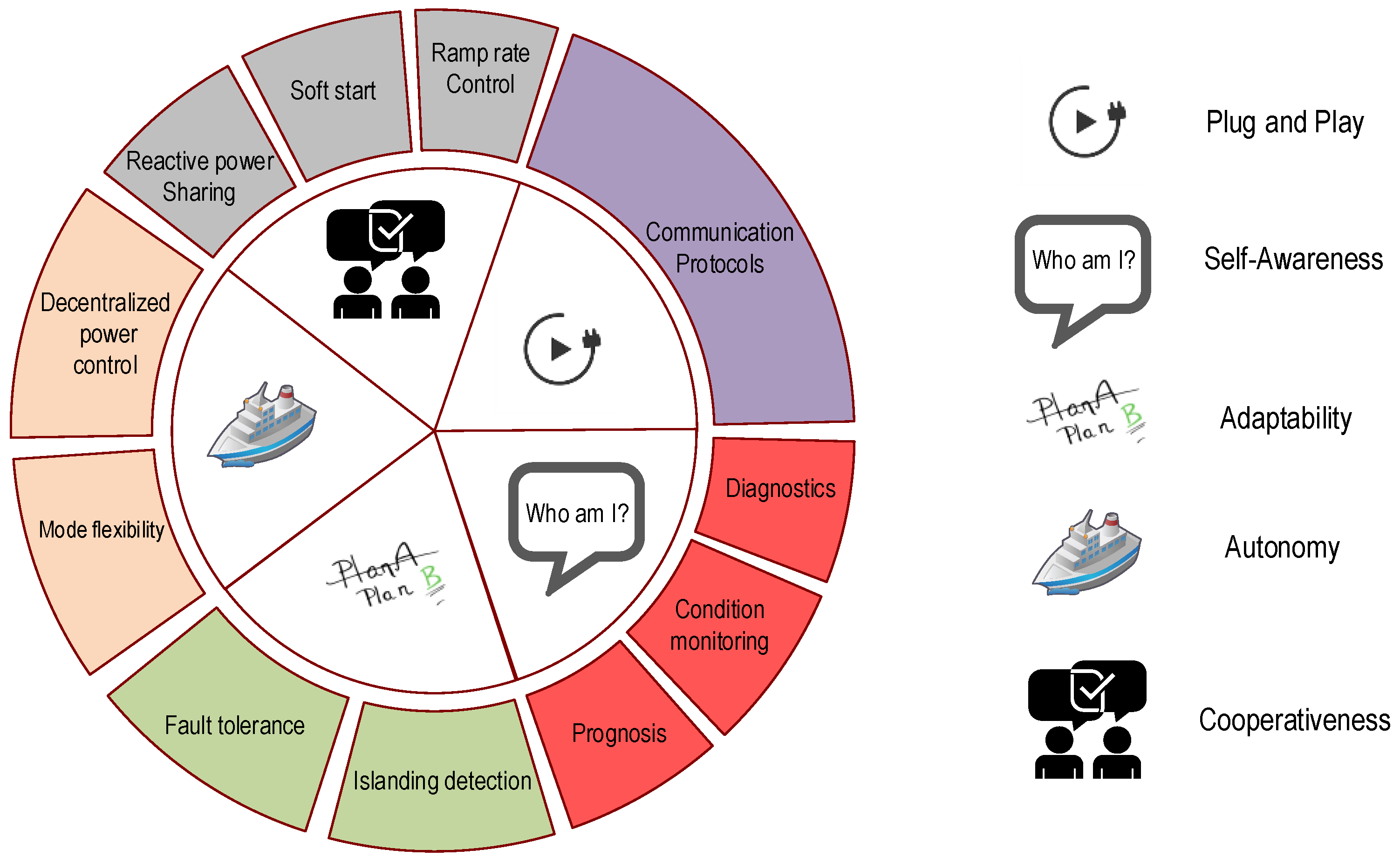
2. Smart Inverters
2.1. Plug and Play
- Data rate: This is one of the most important requirements, as not all of the communication structures are able to provide the required data rate. For example for a home or industrial area network application (HAN and IAN) the required data rate is less than 100 kbps. In contrast to a wide area application (WAN) where this figure can rise to more than 10 Mbps [39].
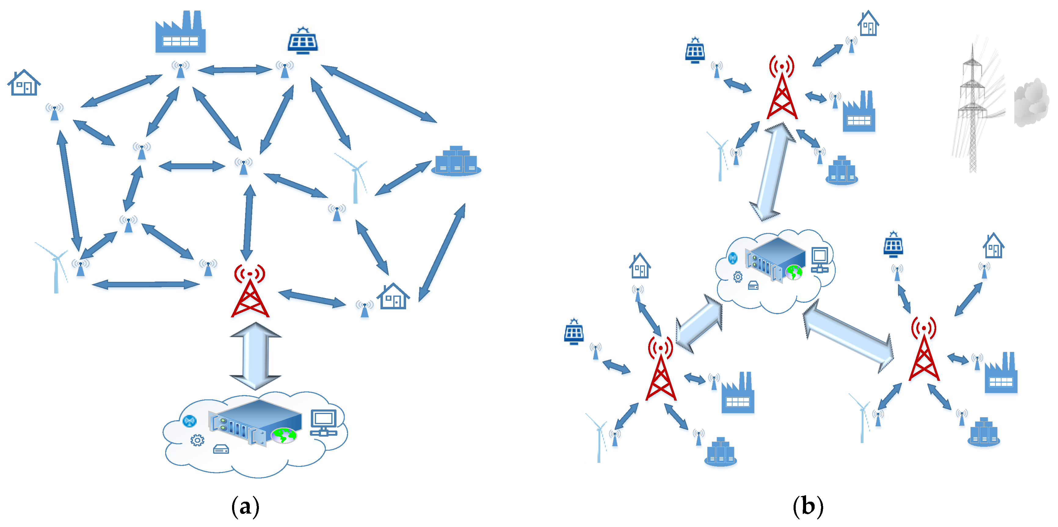
- Range: A microgrid consists of several DGs, energy storage systems (ESSs) and consumers. These are all interfaced to the microgrid bus by inverters that need to be able to communicate. Depending on the size of the microgrid the distance between these points can be noticeable (in the scale of tens of kilometers or more) so no all communication technologies are able to fulfill this requirement.
- Security: If the communication structure is not secure enough [40], the whole system will be vulnerable to both physical and cyber-attacks. This is a challenging aspect regarding some natural characteristics of a smart grid. For example, the smart grid is very sensitive to latency and implementing conventional security measures might introduce new and more delays [41].
- Latency: Depending on the function of the device in a smart grid, the allowed threshold for the latency is different. In the concept of inverter control signals, this allowance is less than ten milliseconds.
- Reliability and Scalability.
2.1.1. Wired Communication Technologies
2.1.2. Wireless Communication Technologies
2.2. Self-Awarness
- Diagnostics so the inverter finds out the reason and origin of a fault after the occurrence.
- Condition monitoring (CM) which is a real-time evaluation of the component health status.
- Prognosis to estimate if a fault is going to happen in the future and when.
2.3. Adaptability
2.3.1. Fault Tolerance
2.3.2. Islanding Detection
2.4. Autonomy
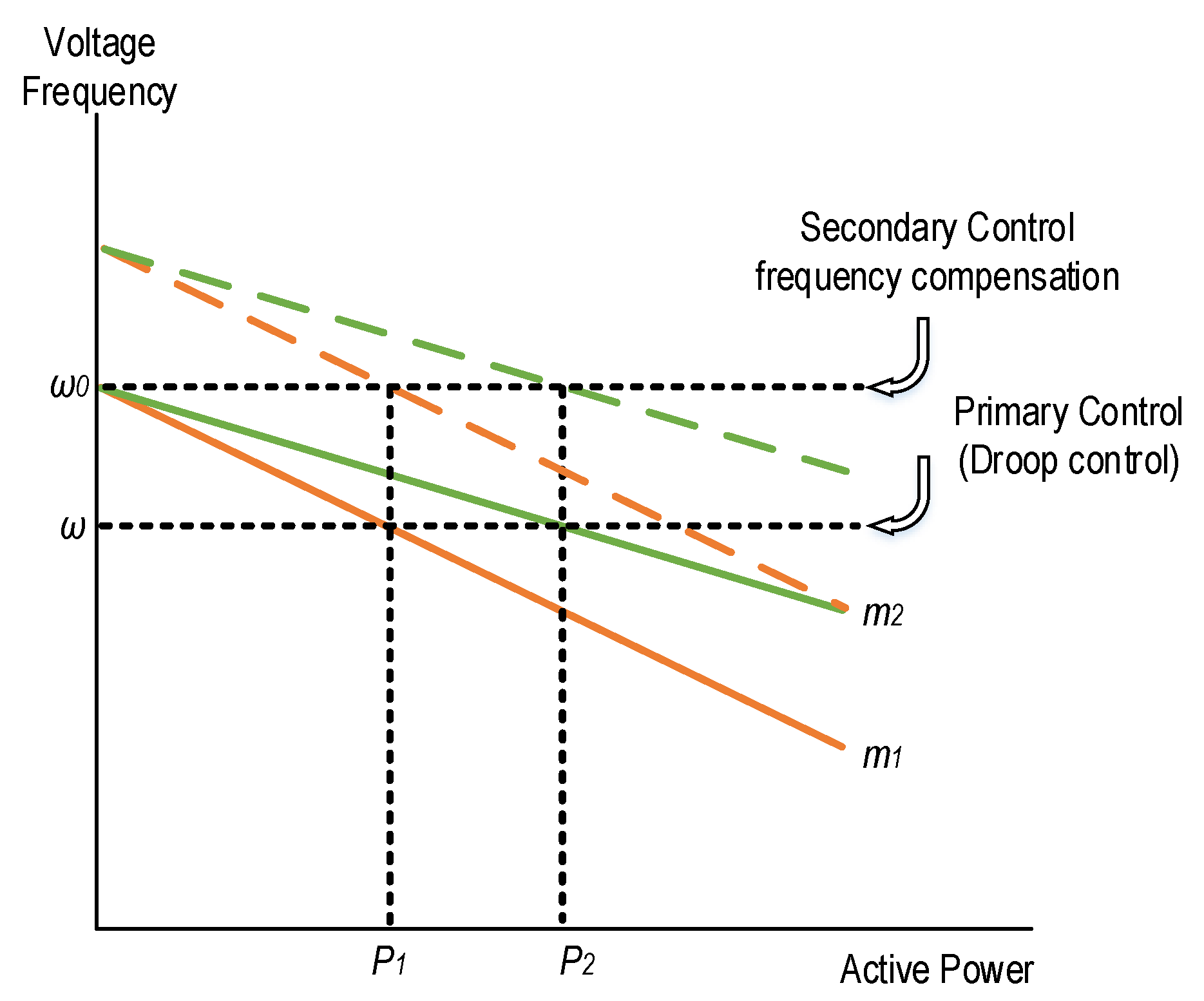
2.4.1. Decentralized Power Control
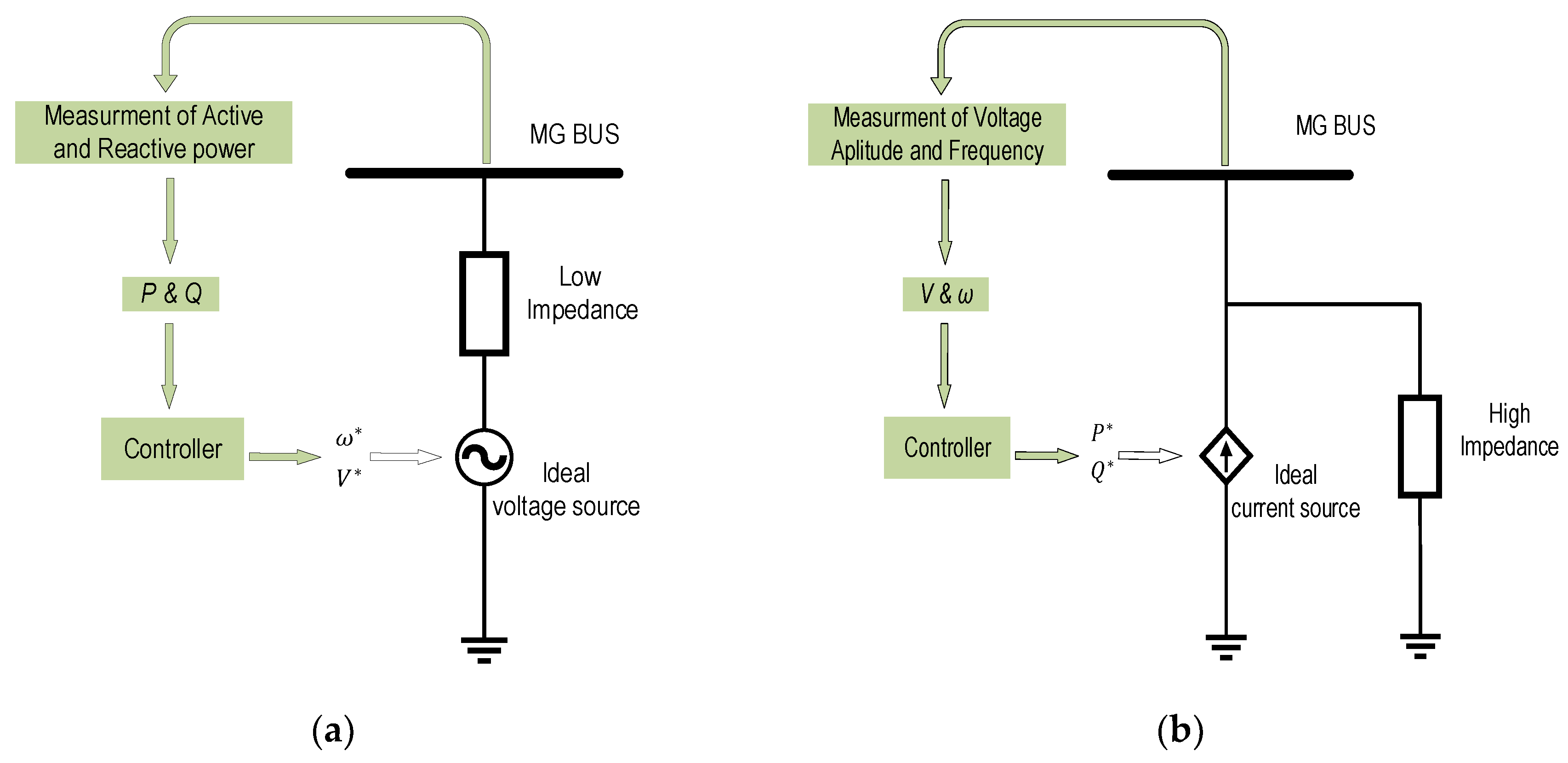
2.4.2. Mode Flexibility
2.5. Cooperativeness
2.5.1. Reactive Power and Harmonic Current Sharing
2.5.2. Soft Start
2.5.3. Ramp Rate Control
3. Discussion
- Plug-and-play capability has been the first concept discussed. Regardless of how much effort has been expended to omit the communication requirement, in order to achieve a stable and functional microgrid, especially in the context of accurate active, reactive and harmonic current sharing, this requirement still exists. In contrast to other smartness indicators that evaluate the smartness based on how less it relies on communication for normal operation, plug-and-play is mainly related to communication compatibility. Different relevant communication technologies have been introduced and investigated in detail with tabular information. The fact that the DGs can be spread over a large area, maybe several kilometers apart, will emphasize the infeasibility of using conventional communication protocols mostly according to economic considerations. One practical and attractive solution can be the use of the Internet. However, in accordance with M2M communication and the Internet of things concept, it is not practical to connect every node of a system directly to the web. A long range, low implementation and operating cost, protocol that is reliable enough at the same time, such as LoRa or ZigBee, can be used to communicate each of the inverters to internet gateways. It is understood, further research and thorough experimental work are required to end up with a conclusion and chose one communication protocol over another.
- Self-awareness is another smartness indicator. In this section, the concept of fault diagnosis, condition monitoring and prognosis have been explained. In addition, fault detection methods have been briefly reviewed since all three-health indicators of inverters require fault detection at some point in their control structure. According to various methods proposed for open-circuit fault detection, it can be observed that, no matter how complicated the detection algorithm could be, there are still based on local measurements with the aim of avoiding the further requirement of communication. Short-circuit fault detection can be effectively conducted by use of hardware and local current measurements.
- Another studied characteristic of smart inverters has been their adaptability. This is related to the change of parameters of the grid, the loads and the working mode of the inverter itself. Here smartness is the ability to sense and identify some fluctuations in the parameters readings that can be an indication for faults. Then, effectively self-adjust to be able to continue to function regardless of the mode change or the fault as it is not always possible to shut down the system immediately even if a serious problem has been detected. This is called fault tolerance, and the different methods have been introduced and compared. Some of them require extra, redundant, hardware and others provide redundancy by manipulating the modulation process. Unintended islanding for microgrids due to grid failure is another issue, and if the system cannot self-adapt itself with this phenomenon, the results can be catastrophic. Methods for islanding detection are different, and they have been briefly introduced and compared. It is understood, same as the fault detection methods, in islanding detection methods the aim of reducing communication requirements and self-adapting in the procedure is a major consideration nowadays.
- The other important characteristic is autonomy, which intends to reduce the requirements for communications among inverters installed far away from each other even more. In microgrids, depending on if it is islanded or grid-connected, the inverters are controlled as VSCs or CSCs connected in parallel. One measure of autonomy is the ability to control the active and reactive power sharing among them with minimum required communication. The droop control methods empower this characteristic by controlling each DGs power flow according to its rated values, by mostly using local measurements to minimizing communication requirements. Another aspect that has been considered here is when the working mode of the microgrid changes from islanded to grid-connected or vice versa. Naturally, in that case, the role of most inverters is required to be changed as well, since in islanded mode the inverters are mostly controlled as grid forming, in contrast to a grid-connected mode when they transform to grid feeding or grid supporting modes. These transformations are required to be done automatically, and each of the inverters should be equipped with suitable control structures to make these mode switching accompanied by unavoidable transient responses seamless and smooth.
- The last concept covered has been cooperativeness. By definition, this means the smartness that an inverter requires to be able to function in accordance and alongside with other inverters in a grid. All the inverters are required to take some responsibility to regulate and compensate for unbalances and disturbances present in the system. In addition, their operation and behavior should be in alignment with other neighboring components. Otherwise, further disturbances will be introduced to the system. Active, reactive and harmonics current sharing is the most important characteristic fitting in this definition. In contrast to some of the characteristics discussed before the requirement of communication can be sensed for cooperativeness.
- Reliable; no data can be lost or misinterpreted.
- Fast, thresholds for delays are very limited.
- Secure, immune from unregistered intervention.
- Globally available and compatible.
- Low energy consumption.
- Robustness.
- Bidirectional.
- Economically feasible, in terms of implementation, operational costs and maintenance.
Author Contributions
Funding
Acknowledgments
Conflicts of Interest
References
- Colson, C.M.; Nehrir, M.H. A review of challenges to real-time power management of microgrids. In Proceedings of the 2009 IEEE Power & Energy Society General Meeting, Calgary, AB, Canada, 26–30 July 2009; pp. 1–8. [Google Scholar]
- Pepermans, G.; Driesen, J.; Haeseldonckx, D.; Belmans, R.; D’haeseleer, W. Distributed generation: Definition, benefits and issues. Energy Policy 2005, 33, 787–798. [Google Scholar] [CrossRef]
- Lasseter, R.; Piagi, P. Microgrid: A Conceptual Solution. In Proceedings of the 2004 IEEE 35th Annual Power Electronics Specialists Conference, Aachen, Germany, 20–25 June 2004. [Google Scholar]
- Marnay, C.; Chatzivasileiadis, S.; Abbey, C.; Iravani, R.; Joos, G.; Lombardi, P.; Mancarella, P.; Von Appen, J. Microgrid evolution roadmap. In Proceedings of the 2015 International Symposium on Smart Electric Distribution Systems and Technologies, Vienna, Austria, 8–11 September 2015; pp. 139–144. [Google Scholar]
- Carrasco, J.M.; Garcia Franquelo, L.; Bialasiewicz, J.T.; Galván, E.; Portillo Guisado, R.C.; Martín Prats, M.D.L.Á.; León, J.I.; Moreno-Alfonso, N. Power-Electronic Systems for the Grid Integration of Renewable Energy Sources: A Survey. IEEE Trans. Ind. Electron. 2004, 53, 1002–1016. [Google Scholar] [CrossRef]
- Prodanović, M.; Green, T.C. Control and filter design of three-phase inverters for high power quality grid connection. IEEE Trans. Power Electron. 2003, 18, 373–380. [Google Scholar] [CrossRef]
- Zhong, Q.C.; Weiss, G. Synchronverters: Inverters that mimic synchronous generators. IEEE Trans. Ind. Electron. 2011, 58, 1259–1267. [Google Scholar] [CrossRef]
- Guerrero, J.M.; Chandorkar, M.; Lee, T.L.; Loh, P.C. Advanced control architectures for intelligent microgridspart i: Decentralized and hierarchical control. IEEE Trans. Ind. Electron. 2013, 60, 1254–1262. [Google Scholar] [CrossRef]
- Guerrero, J.M.; Loh, P.C.; Lee, T.L.; Chandorkar, M. Advanced control architectures for intelligent microgridsPart II: Power quality, energy storage, and AC/DC microgrids. IEEE Trans. Ind. Electron. 2013, 60, 1263–1270. [Google Scholar] [CrossRef]
- Rocabert, J.; Luna, A.; Blaabjerg, F.; Rodríguez, P. Control of power converters in AC microgrids. IEEE Trans. Power Electron. 2012, 27, 4734–4749. [Google Scholar] [CrossRef]
- Kim, J.; Guerrero, J.M.; Rodriguez, P.; Teodorescu, R.; Nam, K. Mode adaptive droop control with virtual output impedances for an inverter-based flexible AC microgrid. IEEE Trans. Power Electron. 2011, 26, 689–701. [Google Scholar] [CrossRef]
- Lu, X.; Guerrero, J.M.; Sun, K.; Vasquez, J.C. An improved droop control method for dc microgrids based on low bandwidth communication with dc bus voltage restoration and enhanced current sharing accuracy. IEEE Trans. Power Electron. 2014, 29, 1800–1812. [Google Scholar] [CrossRef]
- Guerrero, J.M.; Vasquez, J.C.; Matas, J.; De Vicuña, L.G.; Castilla, M. Hierarchical control of droop-controlled AC and DC microgrids—A general approach toward standardization. IEEE Trans. Ind. Electron. 2011, 58, 158–172. [Google Scholar] [CrossRef]
- Yang, N.; Paire, D.; Gao, F.; Miraoui, A.; Liu, W. Compensation of droop control using common load condition in DC microgrids to improve voltage regulation and load sharing. Int. J. Electr. Power Energy Syst. 2015, 64, 752–760. [Google Scholar] [CrossRef]
- Alsafran, A. Literature Review of Power Sharing Control Strategies in Islanded AC Microgrids with Nonlinear Loads. In Proceedings of the 2018 IEEE PES Innovative Smart Grid Technologies Conference Europe (ISGT-Europe), Sarajevo, Bosnia-Herzegovina, 21–25 October 2018; pp. 1–6. [Google Scholar]
- Guerrero, J.M.; de Vicuna, L.G.; Matas, J.; Castilla, M.; Miret, J. A wireless controller to enhance dynamic performance of parallel inverters in distributed generation systems. IEEE Trans. Power Electron. 2004, 19, 1205–1213. [Google Scholar] [CrossRef]
- Kim, J.W.; Choi, H.S.; Cho, B.H. A novel droop method for converter parallel operation. IEEE Trans. Power Electron. 2002, 17, 25–32. [Google Scholar]
- Mihalache, L. Paralleling control technique with no intercommunication signals for resonant controller-based inverters. In Proceedings of the 38th IAS Annual Meeting on Conference Record of the Industry Applications Conference, Salt Lake City, UT, USA, 12–16 October 2003; Volume 3, pp. 1882–1889. [Google Scholar]
- Guerrero, J.M.; de Vicuna, L.; Matas, J.; Castilla, M.; Miret, J. Output Impedance Design of Parallel-Connected {UPS} Inverters With Wireless Load-Sharing Control. IEEE Trans. Ind. Electron. 2005, 52, 1126–1135. [Google Scholar] [CrossRef]
- Converters, T.; Borup, U.; Blaabjerg, F.; Member, S.; Enjeti, P.N. Sharing of Nonlinear Load in Parallel-Connected. IEEE Trans. Ind. Appl. 2001, 37, 1817–1823. [Google Scholar]
- Chang, J.M. Parallel operation of series-connected PWM voltage regulators without control interconnection. Proc. IEEE-Electr. Power Appl. 2001, 148, 141–147. [Google Scholar] [CrossRef]
- Chiang, S.J.; Yen, C.Y.; Chang, K.T. A Multimodule Parallelable Series-Connected. IEEE Trans. Ind. Electron. 2001, 48, 506–516. [Google Scholar] [CrossRef]
- Song, S.H.; Kang, S.I.; Hahm, N.K. Implementation and control of grid connected AC-DC-AC power converter for variable speed wind energy conversion system. In Proceedings of the Eighteenth Annual IEEE Applied Power Electronics Conference and Exposition, Miami Beach, FL, USA, 9–13 February 2003; pp. 154–158. [Google Scholar]
- Kim, J.S.; Sul, S.K. New control scheme for AC-DC-AC converter without DC link electrolytic capacitor. In Proceedings of the IEEE Power Electronics Specialist Conference, Seattle, WA, USA, 20–24 June 1993; pp. 300–306. [Google Scholar]
- Kakigano, H.; Miura, Y.; Uchida, R.; Engineering, I. DC Micro-grid for Super High Quality Distribution. IEEE Power Electron. Spec. Conf. 2010, 25, 3066–3075. [Google Scholar] [CrossRef]
- Salomonsson, D.; Soder, L.; Sannino, A. An Adaptive Control System for a DC Microgrid for Data Centers. IEEE Trans. Ind. Appl. 2008, 44, 1910–1917. [Google Scholar] [CrossRef]
- Che, L.; Shahidehpour, M. DC microgrids: Economic operation and enhancement of resilience by hierarchical control. IEEE Trans. Smart Grid 2014, 5, 2517–2526. [Google Scholar]
- Bidram, A.; Davoudi, A. Hierarchical structure of microgrids control system. IEEE Trans. Smart Grid 2012, 3, 1963–1976. [Google Scholar] [CrossRef]
- Nutkani, I.U.; Loh, P.C.; Wang, P.; Blaabjerg, F. Autonomous droop scheme with reduced generation cost. IEEE Trans. Ind. Electron. 2014, 61, 6803–6811. [Google Scholar] [CrossRef]
- Photovoltaics, D.G.; Storage, E. IEEE Standard for Interconnection and Interoperability of Distributed Energy Resources with Associated Electric Power Systems Interfaces. In IEEE Std 1547-2018 (Revision IEEE Std 1547-2003); IEEE: Piscataway, NJ, USA, 2018; pp. 1–138. [Google Scholar]
- Hoke, A.; Giraldez, J.; Palmintier, B.; Ifuku, E.; Asano, M.; Ueda, R.; Symko-Davies, M. Setting the Smart Solar Standard: Collaborations Between Hawaiian Electric and the National Renewable Energy Laboratory. IEEE Power Energy Mag. 2018, 16, 18–29. [Google Scholar] [CrossRef]
- Mahmud, R.; Hoke, A.; Narang, D. Validating the test procedures described in UL 1741 SA and IEEE. In Proceedings of the 2018 IEEE 7th World Conference on Photovoltaic Energy Conversion (WCPEC), Waikoloa Village, HI, USA, 10–15 June 2018; pp. 1445–1450. [Google Scholar]
- Behravesh, V.; Keypour, R.; Foroud, A.A. Stochastic analysis of solar and wind hybrid rooftop generation systems and their impact on voltage behavior in low voltage distribution systems. Sol. Energy 2018, 166, 317–333. [Google Scholar] [CrossRef]
- Guerrero, J.M.; Xue, Y. Smart Inverters for Utility and Industry Applications. In Proceedings of the PCIM Europe 2015 International Exhibition and Conference for Power Electronics, Intelligent Motion, Renewable Energy and Energy Management, Nuremberg, Germany, 19–20 May 2015; pp. 277–284. [Google Scholar]
- Supriya, S.; Magheshwari, M.; Sree Udhyalakshmi, S.; Subhashini, R. Musthafa Smart grid technologies: Communication technologies and standards. Int. J. Appl. Eng. Res. 2015, 10, 16932–16941. [Google Scholar]
- Gungor, V.C.; Lu, B.; Hancke, G.P. Opportunities and challenges of wireless sensor networks in smart grid. IEEE Trans. Ind. Electron. 2010, 57, 3557–3564. [Google Scholar] [CrossRef]
- Ancillotti, E.; Bruno, R.; Conti, M. The role of communication systems in smart grids: Architectures, technical solutions and research challenges. Comput. Commun. 2013, 36, 1665–1697. [Google Scholar] [CrossRef]
- Kuzlu, M.; Pipattanasomporn, M.; Rahman, S. Communication network requirements for major smart grid applications in HAN, NAN and WAN. Comput. Netw. 2014, 67, 74–88. [Google Scholar] [CrossRef]
- Kuzlu, M.; Pipattanasomporn, M.; Tech, V. Assessment of Communication Technologies and Network Requirements for Different Smart Grid Applications. In Proceedings of the IEEE PES Innovative Smart Grid Technologies Conference (ISGT), Washington, DC, USA, 24–27 February 2013. [Google Scholar]
- Tankard, C. The security issues of the Internet of Things. Comput. Fraud Secur. 2015, 2015, 11–14. [Google Scholar] [CrossRef]
- Bekara, C. Security issues and challenges for the IoT-based smart grid. Procedia Comput. Sci. 2014, 34, 532–537. [Google Scholar] [CrossRef]
- Galli, S.; Scaglione, A.; Wang, Z. For the grid and through the grid: The role of power line communications in the smart grid. Proc. IEEE 2011, 99, 998–1027. [Google Scholar] [CrossRef]
- Yigit, M.; Gungor, V.C.; Tuna, G.; Rangoussi, M.; Fadel, E. Power line communication technologies for smart grid applications: A review of advances and challenges. Comput. Netw. 2014, 70, 366–383. [Google Scholar] [CrossRef]
- Usman, A.; Shami, S.H. Evolution of communication technologies for smart grid applications. Renew. Sustain. Energy Rev. 2013, 19, 191–199. [Google Scholar] [CrossRef]
- Galli, S.; Scaglione, A.; Wang, Z. Power Line Communications and the Smart Grid. In Proceedings of the 2010 First IEEE International Conference on Smart Grid Communications, Gaithersburg, MD, USA, 4–6 October 2010; pp. 303–308. [Google Scholar]
- Kabalci, Y. A survey on smart metering and smart grid communication. Renew. Sustain. Energy Rev. 2016, 57, 302–318. [Google Scholar] [CrossRef]
- Faheem, M.; Shah, S.B.H.; Butt, R.A.; Raza, B.; Anwar, M.; Ashraf, M.W.; Ngadi, M.A.; Gungor, V.C. Smart grid communication and information technologies in the perspective of Industry 4.0: Opportunities and challenges. Comput. Sci. Rev. 2018, 30, 1–30. [Google Scholar] [CrossRef]
- Shaukat, N.; Ali, S.M.; Mehmood, C.A.; Khan, B.; Jawad, M.; Farid, U.; Ullah, Z.; Anwar, S.M.; Majid, M. A survey on consumers empowerment, communication technologies, and renewable generation penetration within Smart Grid. Renew. Sustain. Energy Rev. 2018, 81, 1453–1475. [Google Scholar] [CrossRef]
- Centenaro, M.; Vangelista, L.; Zanella, A.; Zorzi, M. Long-range communications in unlicensed bands: The rising stars in the IoT and smart city scenarios. IEEE Wirel. Commun. 2016, 23, 60–67. [Google Scholar] [CrossRef]
- Laya, A.; Alonso, L.; Alonso-Zarate, J. Is the random access channel of LTE and LTE-A suitable for M2M communications? A survey of alternatives. IEEE Commun. Surv. Tutor. 2014, 16, 4–16. [Google Scholar] [CrossRef]
- Biral, A.; Centenaro, M.; Zanella, A.; Vangelista, L.; Zorzi, M. The challenges of M2M massive access in wireless cellular networks. Digit. Commun. Netw. 2015, 1, 1–19. [Google Scholar] [CrossRef]
- Lien, S.Y.; Chen, K.C.; Lin, Y. Toward ubiquitous massive accesses in 3GPP machine-to-machine communications. IEEE Commun. Mag. 2011, 49, 66–74. [Google Scholar] [CrossRef]
- Townsend, C.; Arms, S. Wireless sensor networks: Principles and aplications. In Sensor Technology Handbook; Wilson, J.S., Ed.; Elsevier: Amsterdam, The Netherlands, 2005; pp. 575–589. [Google Scholar]
- Terashmila, L.K.A.; Iqbal, T.; Mann, G. A comparison of low cost wireless communication methods for remote control of grid-tied converters. In Proceedings of the Canadian Conference on Electrical and Computer Engineering, Windsor, ON, Canada, 30 April–3 May 2017; pp. 1–4. [Google Scholar]
- Thielemans, S.; Bezunartea, M.; Steenhaut, K. Establishing transparent IPv6 communication on LoRa based low power wide area networks (LPWANS). In Proceedings of the 2017 Wireless Telecommunications Symposium (WTS), Chicago, IL, USA, 26–28 April 2017; pp. 1–6. [Google Scholar]
- Angrisani, L.; Arpaia, P.; Bonavolonta, F.; Conti, M.; Liccardo, A. LoRa protocol performance assessment in critical noise conditions. In Proceedings of the 2017 IEEE 3rd International Forum on Research and Technologies for Society and Industry (RTSI), Modena, Italy, 11–13 September 2017. [Google Scholar]
- Lee, J.; Su, Y.; Shen, C. A Comparative Study of Wireless Protocols: Bluetooth, UWB, ZigBee, and Wi-Fi. In Proceedings of the IECON 2007—33rd Annual Conference of the IEEE Industrial Electronics Society, Taipei, Taiwan, 5–8 November 2007; pp. 46–51. [Google Scholar]
- Chen, Y.; Hou, K.M.; Zhou, H.; Shi, H.L.; Liu, X.; Diao, X.; Ding, H.; Li, J.J.; De Vaulx, C. 6LoWPAN stacks: A survey. In Proceedings of the 2011 7th International Conference on Wireless Communications, Networking and Mobile Computing, Wuhan, China, 23–25 September 2011; pp. 1–4. [Google Scholar]
- Ferro, E.; Potortì, F. Bluetooth and Wi-Fi wireless protocols: A survey and a comparison. IEEE Wirel. Commun. 2005, 12, 12–26. [Google Scholar] [CrossRef]
- Chen, J.; Hu, K.; Wang, Q.; Sun, Y.; Shi, Z.; He, S. Narrowband Internet of Things: Implementations and Applications. IEEE Internet Things J. 2017, 4, 2309–2314. [Google Scholar] [CrossRef]
- Petäjäjärvi, J.; Mikhaylov, K.; Roivainen, A.; Hänninen, T.; Pettissalo, M. On the coverage of LPWANs: Range evaluation and channel attenuation model for LoRa technology. In Proceedings of the 2015 14th International Conference on ITS Telecommunications (ITST), Copenhagen, Denmark, 2–4 December 2016; pp. 55–59. [Google Scholar]
- Bardyn, J.P.; Melly, T.; Seller, O.; Sornin, N. IoT: The era of LPWAN is starting now. In Proceedings of the ESSCIRC Conference 2016: 42nd European Solid-State Circuits Conference, Lausanne, Switzerland, 12–15 September 2016; pp. 25–30. [Google Scholar]
- Shaoyong, Y.; Dawei, X.; Angus, B.; Philip, M.; Li, R.; Peter, T. Condition Monitoring for Device Reliability in Power Electronic Converters: A Review. IEEE Trans. Power Electron. 2010, 25, 2734–2752. [Google Scholar]
- Oh, H.; Han, B.; McCluskey, P.; Han, C.; Youn, B.D. Physics-of-failure, condition monitoring, and prognostics of insulated gate bipolar transistor modules: A review. IEEE Trans. Power Electron. 2015, 30, 2413–2426. [Google Scholar] [CrossRef]
- Lamb, J.; Mirafzal, B. Open-Circuit IGBT Fault Detection and Location Isolation for Cascaded Multilevel Converters. IEEE Trans. Ind. Electron. 2017, 64, 4846–4856. [Google Scholar] [CrossRef]
- Lu, B.; Sharma, S.K. A literature review of IGBT fault diagnostic and protection methods for power inverters. IEEE Trans. Ind. Appl. 2009, 45, 1770–1777. [Google Scholar]
- Estima, J.O.; Cardoso, A.J.M. A new approach for real-time multiple open-circuit fault diagnosis in voltage-source inverters. IEEE Trans. Ind. Appl. 2011, 47, 2487–2494. [Google Scholar] [CrossRef]
- Zeineldin, H.H.; Kan’an, N.H.; Casagrande, E.; Woon, W.L. Data mining approach to fault detection for isolated inverter-based microgrids. IET Gener. Transm. Distrib. 2013, 7, 745–754. [Google Scholar]
- Moosavi, S.S.; Kazemi, A.; Akbari, H. A comparison of various open-circuit fault detection methods in the IGBT-based DC/AC inverter used in electric vehicle. Eng. Fail. Anal. 2019, 96, 223–235. [Google Scholar] [CrossRef]
- An, Q.T.; Sun, L.Z.; Sun, L.; Jahns, T.M. Low-cost diagnostic method for open-switch faults in inverters. Electron. Lett. 2010, 46, 1021. [Google Scholar] [CrossRef]
- Mendes, A.M.S.; Cardoso, A.J.M. Voltage Source Inverter Fault in Variable Speed Ac Current Approach. In Proceedings of the IEEE International Electric Machines and Drives Conference, Seattle, WA, USA, 9–12 May 1999; pp. 704–706. [Google Scholar]
- Peuget, R.; Courtine, S.; Rognon, J.P. Fault detection and isolation on a pwm inverter. IEEE Trans. Ind. Appl. 1997, 34, 1471–1478. [Google Scholar]
- De Araujo Ribeiro, R.L.; Jacobina, C.B.; Da Silva, E.R.C.; Lima, A.M.N. Fault detection of open-switch damage in voltage-fed PWM motor drive systems. IEEE Trans. Power Electron. 2003, 18, 587–593. [Google Scholar] [CrossRef]
- Zhang, W.; Xu, D.; Enjeti, P.N.; Li, H.; Hawke, J.T.; Krishnamoorthy, H.S. Survey on fault-tolerant techniques for power electronic converters. IEEE Trans. Power Electron. 2014, 29, 6319–6331. [Google Scholar] [CrossRef]
- Lezana, P.; Pou, J.; Meynard, T.A.; Rodriguez, J.; Ceballos, S.; Richardeau, F. Survey on fault operation on multilevel inverters. IEEE Trans. Ind. Electron. 2010, 57, 2207–2218. [Google Scholar] [CrossRef]
- Andreu, J.; Kortabarria, I.; Ibarra, E.; Martínez De Alegría, I.; Robles, E. A new hardware solution for a fault tolerant matrix converter. In Proceedings of the 2009 35th Annual Conference of IEEE Industrial Electronics, Porto, Portugal, 3–5 November 2009; pp. 4469–4474. [Google Scholar]
- Weber, P.; Poure, P.; Theilliol, D.; Saadate, S. Design of hardware fault tolerant control architecture for Wind Energy Conversion System with DFIG based on reliability analysis. In Proceedings of the 2008 IEEE International Symposium on Industrial Electronics, Cambridge, UK, 30 June–2 July 2008; pp. 2323–2328. [Google Scholar]
- Rodríguez, M.A.; Claudio, A.; Theilliol, D.; Vela, L.G.; Hernández, L. Strategy to replace the damaged power device for fault-tolerant induction motor drive. In Proceedings of the 2009 Twenty-Fourth Annual IEEE Applied Power Electronics Conference and Exposition, Washington, DC, USA, 15–19 February 2009; Volume 52, pp. 343–346. [Google Scholar]
- Li, S.; Xu, L. Strategies of fault tolerant operation for three-level PWM inverters. IEEE Trans. Power Electron. 2006, 21, 933–940. [Google Scholar] [CrossRef]
- Yi, Z.; Hongge, S.; Bin, X. Optimization of neutral shift in cell-fault treatment for cascaded H-bridge. In Proceedings of the 2008 International Conference on Electrical Machines and Systems, Wuhan, China, 17–20 October 2008; pp. 1683–1685. [Google Scholar]
- Correa, P.; Pacas, M.; Rodríguez, J. Modulation strategies for fault-tolerant operation of H-bridge multilevel inverters. IEEE Int. Symp. Ind. Electron. 2006, 2, 1589–1594. [Google Scholar]
- Mahat, P.; Chen, Z.; Bak-Jensen, B. Review of Islanding Detection Methods for Distributed Generation. In Proceedings of the 2008 Third International Conference on Electric Utility Deregulation and Restructuring and Power Technologies, Nanjing, China, 6–9 April 2008; Volume 88, pp. 2743–2748. [Google Scholar]
- De Mango, F.; Liserre, M.; Dell’Aquila, A.; Pigazo, A. Overview of anti-islanding algorithms for PV systems. Part I: Passive methods. In Proceedings of the 2006 12th International Power Electronics and Motion Control Conference, Portoroz, Slovenia, 30 August–1 September 2007; pp. 1–6. [Google Scholar]
- Li, C.; Cao, C.; Cao, Y.; Kuang, Y.; Zeng, L.; Fang, B. A review of islanding detection methods for microgrid. Renew. Sustain. Energy Rev. 2014, 35, 211–220. [Google Scholar] [CrossRef]
- Kim, K.-H.; Jang, S.-I. An Islanding Detection Method for Distributed Generations Using Voltage Unbalance and Total Harmonic Distortion of Current. IEEE Trans. Power Deliv. 2004, 19, 745–752. [Google Scholar]
- Pai, F.-S.; Huang, S.-J. A detection algorithm for islanding-prevention of dispersed consumer-owned storage and generating units. IEEE Trans. Energy Convers. 2001, 16, 346–351. [Google Scholar] [CrossRef]
- Ciobotaru, M.; Teodorescu, R.; Blaabjerg, F. On-line grid impedance estimation based on harmonic injection for grid-connected PV inverter. In Proceedings of the 2007 IEEE International Symposium on Industrial Electronics, Vigo, Spain, 4–7 June 2007; pp. 2437–2442. [Google Scholar]
- Asiminoaei, L.; Teodorescu, R.; Blaabjerg, F.; Borup, U. A digital controlled PV-inverter with grid impedance estimation for ENS detection. IEEE Trans. Power Electron. 2005, 20, 1480–1490. [Google Scholar] [CrossRef]
- Asiminoaei, L.; Teodorescu, R.; Blaabjerg, F.; Borup, U. A new method of on-line grid impedance estimation for PV inverter. In Proceedings of the Nineteenth Annual IEEE Applied Power Electronics Conference and Exposition, Anaheim, CA, USA, 22–26 February 2004; pp. 1527–1533. [Google Scholar]
- Hua, C.; Liao, K.; Lin, J.; City, T.; Country, Y. Parallel Operation of Inverters for Distributed Photovoltaic Power Supply System. In Proceedings of the 2002 IEEE 33rd Annual IEEE Power Electronics Specialists Conference, Cairns, Australia, 23–27 June 2002; pp. 1979–1983. [Google Scholar]
- Simpson-Porco, J.W.; Dörfler, F.; Bullo, F. Synchronization and power sharing for droop-controlled inverters in islanded microgrids. Automatica 2013, 49, 2603–2611. [Google Scholar] [CrossRef]
- Tuladha, A.; Jin, H.; Unger, T.; Mauch, K. Control of parrallel invertes in distribited AC power systems with considerartion of the line impedance effect. IEEE Trans. Ind. Appl. 1998, 36, 321–328. [Google Scholar]
- Vasquez, J.C.; Guerrero, J.M.; Savaghebi, M.; Eloy-Garcia, J.; Teodorescu, R. Modeling, analysis, and design of stationary-reference-frame droop-controlled parallel three-phase voltage source inverters. IEEE Trans. Ind. Electron. 2013, 60, 1271–1280. [Google Scholar] [CrossRef]
- Guerrero, J.M.; Vásquez, J.C.; Matas, J.; Castilla, M.; García de Vicuna, L. Control strategy for flexible microgrid based on parallel line-interactive UPS systems. IEEE Trans. Ind. Electron. 2009, 56, 726–736. [Google Scholar] [CrossRef]
- Yu, X.; Khambadkone, A.M.; Wang, H.; Terence, S.T.S. Control of parallel-connected power converters for low-voltage microgrid—Part I: A hybrid control architecture. IEEE Trans. Power Electron. 2010, 25, 2962–2970. [Google Scholar] [CrossRef]
- Yao, W.; Chen, M.; Matas, J.; Guerrero, J.M.; Qian, Z.M. Design and analysis of the droop control method for parallel inverters considering the impact of the complex impedance on the power sharing. IEEE Trans. Ind. Electron. 2011, 58, 576–588. [Google Scholar] [CrossRef]
- Mohamed, Y.A.R.I.; El-Saadany, E.F. Adaptive decentralized droop controller to preserve power sharing stability of paralleled inverters in distributed generation microgrids. IEEE Trans. Power Electron. 2008, 23, 2806–2816. [Google Scholar] [CrossRef]
- Zhong, Q.C. Robust droop controller for accurate proportional load sharing among inverters operated in parallel. IEEE Trans. Ind. Electron. 2013, 60, 1281–1290. [Google Scholar] [CrossRef]
- Guerrero, J.M.; Matas, J.; De Vicuña, L.G.; Castilla, M.; Miret, J. Wireless-control strategy for parallel operation of distributed-generation inverters. IEEE Trans. Ind. Electron. 2006, 53, 1461–1470. [Google Scholar] [CrossRef]
- Monshizadeh, P.; De Persis, C.; Monshizadeh, N.; Van Der Schaft, A. A communication-free master-slave microgrid with power sharing. In Proceedings of the 2016 American Control Conference (ACC), Boston, MA, USA, 6–8 July 2016; pp. 3564–3569. [Google Scholar]
- Wang, J.; Chang, N.C.P.; Feng, X.; Monti, A. Design of a Generalized Control Algorithm for Parallel Inverters for Smooth Microgrid Transition Operation. IEEE Trans. Ind. Electron. 2015, 62, 4900–4914. [Google Scholar] [CrossRef]
- Katiraei, F.; Iravani, M.R.; Lehn, P.W. Micro-grid autonomous operation during and subsequent to islanding process. IEEE Trans. Power Deliv. 2005, 20, 248–257. [Google Scholar] [CrossRef]
- Hu, S.H.; Kuo, C.Y.; Lee, T.L.; Guerrero, J.M. Droop-controlled inverters with seamless transition between islanding and grid-connected operations. In Proceedings of the 2011 IEEE Energy Conversion Congress and Exposition, Phoenix, AZ, USA, 17–22 September 2011; pp. 2196–2201. [Google Scholar]
- Vandoorn, T.L.; Meersman, B.; De Kooning, J.D.M.; Vandevelde, L. Transition from islanded to grid-connected mode of microgrids with voltage-based droop control. IEEE Trans. Power Syst. 2013, 28, 2545–2553. [Google Scholar] [CrossRef]
- Tran, T.V.; Chun, T.W.; Lee, H.H.; Kim, H.G.; Nho, E.C. PLL-based seamless transfer control between grid-connected and islanding modes in grid-connected inverters. IEEE Trans. Power Electron. 2014, 29, 5218–5228. [Google Scholar] [CrossRef]
- Jin, C.; Gao, M.; Lv, X.; Chen, M. A seamless transfer strategy of islanded and grid-connected mode switching for microgrid based on droop control. In Proceedings of the 2012 IEEE Energy Conversion Congress and Exposition (ECCE), Raleigh, NC, USA, 15–20 September 2012; pp. 969–973. [Google Scholar]
- He, J.; Li, Y.W.; Blaabjerg, F. An enhanced islanding microgrid reactive power, imbalance power, and harmonic power sharing scheme. IEEE Trans. Power Electron. 2015, 30, 3389–3401. [Google Scholar] [CrossRef]
- Guerrero, J.M.M.; Matas, J.; Garcia de Vicuna, L.; Berbel, N.; Sosa, J. Wireless-Control Strategy for Parallel Operation of Distributed Generation Inverters. In Proceedings of the IEEE International Symposium on Industrial Electronics, Dubrovnik, Croatia, 20–23 June 2005; pp. 845–850. [Google Scholar]
- Axelrod, B.; Berkovich, Y.; Ioinovici, A. Virtual Impedance Loop for Droop-Controlled Single-Phase Parallel Inverters Using a Second-Order. In Proceedings of the 2003 International Symposium on Circuits and Systems, Bangkok, Thailand, 25–28 May 2003; pp. 2993–3002. [Google Scholar]
- Han, H.; Liu, Y.; Sun, Y.; Su, M.; Guerrero, J.M. An improved droop control strategy for reactive power sharing in islanded microgrid. IEEE Trans. Power Electron. 2015, 30, 3133–3141. [Google Scholar] [CrossRef]
- Yaoqin, J.; Dingkun, L.; Shengkui, P. Improved droop control of parallel inverter system in standalone microgrid. In Proceedings of the 8th International Conference on Power Electronics—ECCE Asia, Jeju, Korea, 30 May–3 June 2011; pp. 1506–1513. [Google Scholar]
- He, J.; Li, Y.W. An enhanced microgrid load demand sharing strategy. IEEE Trans. Power Electron. 2012, 27, 3984–3995. [Google Scholar] [CrossRef]
- Vandoorn, T.; Meersman, B.; De Kooning, J.; Vandevelde, L. Controllable harmonic current sharing in islanded microgrids: DG units with programmable resistive behavior toward harmonics. IEEE Trans. Power Deliv. 2012, 27, 831–841. [Google Scholar] [CrossRef]
- Sreekumar, P.; Khadkikar, V. Nonlinear load sharing in low voltage microgrid using negative virtual harmonic impedance. In Proceedings of the IECON 2015—41st Annual Conference of the IEEE Industrial Electronics Society, Yokohama, Japan, 9–12 November 2015; pp. 3353–3358. [Google Scholar]
- Lorzadeh, I.; Abyaneh, H.A.; Savaghebi, M.; Guerrero, J.M. A hierarchical control scheme for reactive power and harmonic current sharing in islanded microgrids. In Proceedings of the 2015 17th European Conference on Power Electronics and Applications (EPE’15 ECCE-Europe), Geneva, Switzerland, 8–10 September 2015; pp. 1–10. [Google Scholar]
- Moussa, H.; Shahin, A.; Martin, J.P.; Nahid-Mobarakeh, B.; Pierfederici, S.; Moubayed, N. Harmonic Power Sharing with Voltage Distortion Compensation of Droop Controlled Islanded Microgrids. IEEE Trans. Smart Grid 2018, 9, 5335–5347. [Google Scholar] [CrossRef]
- Micallef, A.; Apap, M.; Spiteri-Staines, C.; Guerrero, J.M. Mitigation of Harmonics in Grid-Connected and Islanded Microgrids Via Virtual Admittances and Impedances. IEEE Trans. Smart Grid 2017, 8, 651–661. [Google Scholar] [CrossRef]
- Guerrero, J.M.; Berbel, N.; Matas, J.; Sosa, J.L.; De Vicuña, L.G. Control of line-interactive UPS connected in parallel forming a microgrid. In Proceedings of the IEEE International Symposium on Industrial Electronics, Vigo, Spain, 4–7 June 2007; pp. 2667–2672. [Google Scholar]
- Chen, Y.; Wang, Z.; Zhou, X.; Zhou, L.; Chen, Z.; Luo, A.; Wang, M. Seamless transfer control strategy for three-phase inverter in microgrid. In Proceedings of the 2016 IEEE 8th International Power Electronics and Motion Control Conference (IPEMC-ECCE Asia), Hefei, China, 22–26 May 2016; pp. 1759–1763. [Google Scholar]
- Guerrerol, J.M.; Berbel, N.; Matas, J.; Sosa, J.L.; De Vicufia, L.G. Droop Control Method with Virtual Output Impedance for Parallel Operation of Uninterruptible Power Supply Systems in a Microgrid. In Proceedings of the APEC 07—Twenty-Second Annual IEEE Applied Power Electronics Conference and Exposition, Anaheim, CA, USA, 25 February–1 March 2007. [Google Scholar]
- Guerrero, J.M.; Hang, L.; Uceda, J. Control of Distributed Uninterruptible Power Supply Systems. IEEE Trans. Ind. Electron. 2008, 55, 2845–2859. [Google Scholar] [CrossRef]
- Sangwongwanich, A.; Yang, Y.; Blaabjerg, F. A cost-effective power ramp-rate control strategy for single-phase two-stage grid-connected photovoltaic systems. In Proceedings of the 2016 IEEE Energy Conversion Congress and Exposition (ECCE), Milwaukee, WI, USA, 18–22 September 2016; pp. 1–7. [Google Scholar]
- Salehi, V.; Radibratovic, B. Ramp rate control of photovoltaic power plant output using energy storage devices. In Proceedings of the 2014 IEEE PES General Meeting|Conference & Exposition, National Harbor, MD, USA, 27–31 July 2014; pp. 1–5. [Google Scholar]
- Kakimoto, N.; Satoh, H.; Takayama, S.; Nakamura, K. Ramp-rate control of photovoltaic generator with electric double-layer capacitor. IEEE Trans. Energy Convers. 2009, 24, 465–473. [Google Scholar] [CrossRef]
- Van Haaren, R.; Morjaria, M.; Fthenakis, V. An energy storage algorithm for ramp rate control of utility scale PV (photovoltaics) plants. Energy 2015, 91, 894–902. [Google Scholar] [CrossRef]
- Kasem, A.H.; El-Saadany, E.F.; El-Tamaly, H.H.; Wahab, M.A.A. Power ramp rate control and flicker mitigation for directly grid connected wind turbines. IET Renew. Power Gener. 2010, 4, 261. [Google Scholar] [CrossRef]
- Cormode, D.; Cronin, A.D.; Richardson, W.; Lorenzo, A.T.; Brooks, A.E.; Dellagiustina, D.N. Comparing ramp rates from large and small PV systems, and selection of batteries for ramp rate control. In Proceedings of the 2013 IEEE 39th Photovoltaic Specialists Conference (PVSC), Tampa, FL, USA, 16–21 June 2013; pp. 1805–1810. [Google Scholar]
- De la Parra, I.; Marcos, J.; García, M.; Marroyo, L. Control strategies to use the minimum energy storage requirement for PV power ramp-rate control. Sol. Energy 2015, 111, 332–343. [Google Scholar] [CrossRef]
- Marcos, J.; Storkël, O.; Marroyo, L.; Garcia, M.; Lorenzo, E. Storage requirements for PV power ramp-rate control. Sol. Energy 2014, 99, 28–35. [Google Scholar] [CrossRef]


| Technology | Data Rate | Coverage | Disadvantages | References | |
|---|---|---|---|---|---|
| PLC | NB | 10–500 kbps | 150 km | Difficult to achieve high bit rates. Signal attenuation. Interference from electric component connected to the line. | [37,38,46,47,48] |
| BB | 10–200 Mbps | 1.5 km | |||
| Fiber optics | PON | 100 Mbps–2.5 Gbps | 10–60 km | High capital costs. Difficult to upgrade. | |
| AON | 100 Mbps | 10 km | |||
| DSL | HDSL | 2 Mbps | 3.6 km | Possible data quality degradation. High operational costs. | |
| ADSL | 1.3–8 Mbps | 5 km | |||
| VDSL | 16–85 Mbps | 1200 m | |||
| Technology | Data Rate | Coverage | Disadvantages | References | |
|---|---|---|---|---|---|
| Cellular network communication | GSM | Max 14.4 Kbps | 1–10 Km | Data rates low | [35] |
| GPRS | Max 170 Kbps | 1–10 Km | Data rates low | ||
| 3G | Max 2 Mbps | 1–10 Km | High cost | ||
| WIMAX | Max 75 Mbps | Max 50 Km | Availability limited | ||
| Short range | ZigBee | 250 Kbps | Approx 50 m | Short range and low data rate | [35,49,57] |
| 6LoWPAN | 250 Kbps | 10–100 m | Short range and low data rate | [58] | |
| Bluetooth | 1–2 Mbps | 15–30 m | Short range | [49,59] | |
| Wi-Fi | 54 Mb/s | 100 m | Short range | [49,57,59] | |
| UWB | 110 Mb/s | 10 m | Very short range | ||
| LPWAN | LoRa | 0.3–37.5 Kbps | 3–5 Km (Urban) 10–15 Km (Rural) | Low data range | [49,60,61] |
| SIGFOX | 0.1 Kbps | 3–10 Km (Urban) 30–50 Km (Rural) | Low data range | ||
| eMTC | Less than 1 Mbps | 5 km (urban) 17 km (rural) | Licensed network | ||
© 2019 by the authors. Licensee MDPI, Basel, Switzerland. This article is an open access article distributed under the terms and conditions of the Creative Commons Attribution (CC BY) license (http://creativecommons.org/licenses/by/4.0/).
Share and Cite
Arbab-Zavar, B.; Palacios-Garcia, E.J.; Vasquez, J.C.; Guerrero, J.M. Smart Inverters for Microgrid Applications: A Review. Energies 2019, 12, 840. https://doi.org/10.3390/en12050840
Arbab-Zavar B, Palacios-Garcia EJ, Vasquez JC, Guerrero JM. Smart Inverters for Microgrid Applications: A Review. Energies. 2019; 12(5):840. https://doi.org/10.3390/en12050840
Chicago/Turabian StyleArbab-Zavar, Babak, Emilio J. Palacios-Garcia, Juan C. Vasquez, and Josep M. Guerrero. 2019. "Smart Inverters for Microgrid Applications: A Review" Energies 12, no. 5: 840. https://doi.org/10.3390/en12050840
APA StyleArbab-Zavar, B., Palacios-Garcia, E. J., Vasquez, J. C., & Guerrero, J. M. (2019). Smart Inverters for Microgrid Applications: A Review. Energies, 12(5), 840. https://doi.org/10.3390/en12050840