Article

An Active Common-Mode Voltage Canceler for PWM Converters in Wind-Turbine Doubly-Fed Induction Generators

1
Energy Resources Engineering Department, Egypt-Japan University of Science and Technology (E-JUST), Alexandria 21934, Egypt
2
Electrical Power and Machines Engineering Department, Tanta University, Gharbeya 31512, Egypt
3
Electrical Engineering Department, Assiut University, Assiut 71516, Egypt
4
Mechanical Engineering Department, Assiut University, Assiut 71516, Egypt
*
Author to whom correspondence should be addressed.
Energies 2019, 12(4), 691; https://doi.org/10.3390/en12040691
Submission received: 24 January 2019 / Revised: 13 February 2019 / Accepted: 18 February 2019 / Published: 21 February 2019
(This article belongs to the Special Issue Power Electronic Systems for Efficient and Sustainable Energy Supply)

Abstract

:
Wind energy integration in power grids is increasing day by day to reduce the use of fossil fuels, and consequently greenhouse gas emissions. Using the pulse-width modulated (PWM) power converters in wind turbine generators, specifically in doubly-fed induction generators, results in generating a common-mode voltage (CMV). This common-mode voltage causes a flow of common-mode current (CMC) that leaks through the stray capacitances in the generator structure. These currents impose a voltage on the generator bearing which may deteriorate them. In the current work, an active common-mode voltage canceler (ACMVC) is developed to eliminate the CMV produced by a PWM converter. The ACMVC generates a compensating voltage at the converter terminals to eliminate the CMV with a subsequent reduction of the voltage stress on the generator bearing. This compensating voltage has the same amplitude as CMV, but opposite polarity. A simulation of the ACMVC model is performed using the PSCAD/EMTDC (Electromagnetic Transient Design and Control) software package. Results confirm the effectiveness of ACMVC in canceling not only the CMV but the CMC and bearing voltage as well. In addition, the relationship between the rise time of CMV and the peak value of CMC is investigated.

1. Introduction

With the increase of carrier frequency in pulse-width modulated (PWM) converters driving an AC motor, leakage currents with a frequency in the range from 100 kHz to several megahertz flow to earth via stray capacitors inside the motor. These currents build up the so-called common-mode voltage (CMV) between the rotor neutral point and the ground. In addition, these currents may influence adversely motor control circuits and result in incorrect operation of zero-sequence relays. Moreover, these currents can cause a shortening of the insulation life of motors and transformers [1,2].
There have been many attempts to eliminate the common-mode voltage or current by using passive and active elements. An example of using passive elements is the common-mode choke and the common-mode transformer. A common-mode choke connected in series between the terminals of the converter and motor terminals has been used to reduce the unwanted leakage current [3,4]. The conventional common-mode choke is not effective for decreasing the average and rms values of the leakage current, but only effective in reducing its peak value. A common-mode transformer with an additional winding shorted by a resistor has been proposed [5] to dampen the oscillatory ground current and the CMV. This transformer is capable of decreasing the leakage current rms value to about 25%, even when its core is smaller than that of the common-mode choke. The main problem of the common-mode transformer is that a small amount of the ground current still exists. An active common-mode canceler (ACC) has been used for an induction motor drive [1] to eliminate the CMV produced by the PWM converter. The ACC produces a compensating voltage which has the same amplitude of the CMV produced by the converter but with opposite polarity. Hence, the CMV produced at converter’s terminal can be reduced significantly.
Due to the advantages of wind energy being a clean source with a short installation period and a low operational cost, it is considered one of the most important renewable energy technologies. Doubly-fed induction generators (DFIGs) are one of the most widely used wind energy technologies. The rating of the converters in DFIG is only 30% of the total rated power, hence the cost and size of the system is greatly decreased [6,7]. It is reported that approximately 40% of the generated energy from wind turbines (WTs) is already produced by doubly-fed machines and this rate is still increasing [8]. The WT mechanical power is naturally changed with variable turbine speeds and variable output voltage. Hence, power electronic converters with pulse-width modulation (PWM) techniques are widely used to provide the required frequency with suitable separate control of active and reactive powers [9].
In the super-synchronous mode of the DFIG, the rotor current of a generator with a few Hz frequency flows through an AC–DC converter, DC link and DC–AC converter to increase the frequency to the power value before connection to the power grid. Subsequently, a high-frequency CMV between the neutral point of the generator and the ground will be developed, the same as demonstrated before for induction motors driven by voltage-source PWM converter [1,2]. This voltage is applied across the generator stray capacitances and generates a bearing voltage between the inner raceway and outer raceway of the generator bearing. If the bearing voltage overrides the threshold voltage of the bearing, the lubricating oil-film of the bearing will break down. Therefore, a discharge current due to high-frequency CMV [10,11,12] will flow, resulting in a bearing failure [6,13]. Compared to AC industrial motors, the bearing failure of WT generators is higher [14]. A comparison was made between the bearing current problems in three types of WT generators, namely a DFIG, a direct-drive permanent magnet synchronous generator (PMSG), and semi-direct-drive PMSG turbines [6] with no proposal for any technique to reduce the bearing currents. An ACC has been used before [1] to eliminate the common-mode voltage (CMV) in an induction motor drive using an insulated gate bipolar transistor (IGBT) inverter.
In this paper, the active common-mode voltage canceler (ACMVC) technique is introduced to reduce the CMV generated by the PWM converter of a wind turbine generator (DFIG). The ACMVC is connected at the rotor terminals before connection to the AC-DC converter. Also, the stray equivalent circuit of the DFIG, including different capacitances between conducting parts inside the generator, has been considered in the simulation model. The temporal variation of the CMV, the leakage current to ground (common-mode current, CMC) and the bearing voltage (shaft voltage) are calculated with and without the use of ACMVC to evaluate its effectiveness. The dependency of the peak value of CMC on the rise time of CVM, which was not studied before [1,2], is also studied in the present work.
The main highlights of this paper can be summarized as follows:
  • The terminals of the PWM converter of the DFIG are connected to the rotor winding through the proposed ACMVC to suppress the CMV generated at the converter terminals.
  • The stray capacitances of the DFIG, including those between conducting parts inside the generator, have been considered in the equivalent circuit of the DFIG.
  • The bearing induced voltage (shaft voltage) and the leakage current to the ground (CMC) are calculated with and without the use of the proposed ACMVC to evaluate its effectiveness.
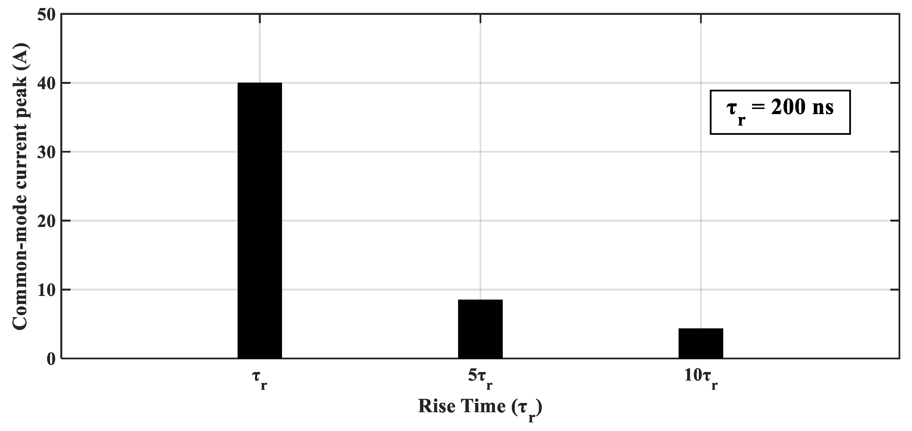
  • The rise time of CMV and the peak value of CMC are correlated in the present work.
This paper is organized in sections. In Section 2 the CMV of the converter is introduced. Then, the types of stray capacitances inside the DFIG are illustrated in Section 3. This is followed by the operation and design of the proposed ACMVC in Section 4. Section 5 presents the simulation results and discussions. Finally, the main conclusions that can be extracted from the present work are listed in Section 6.

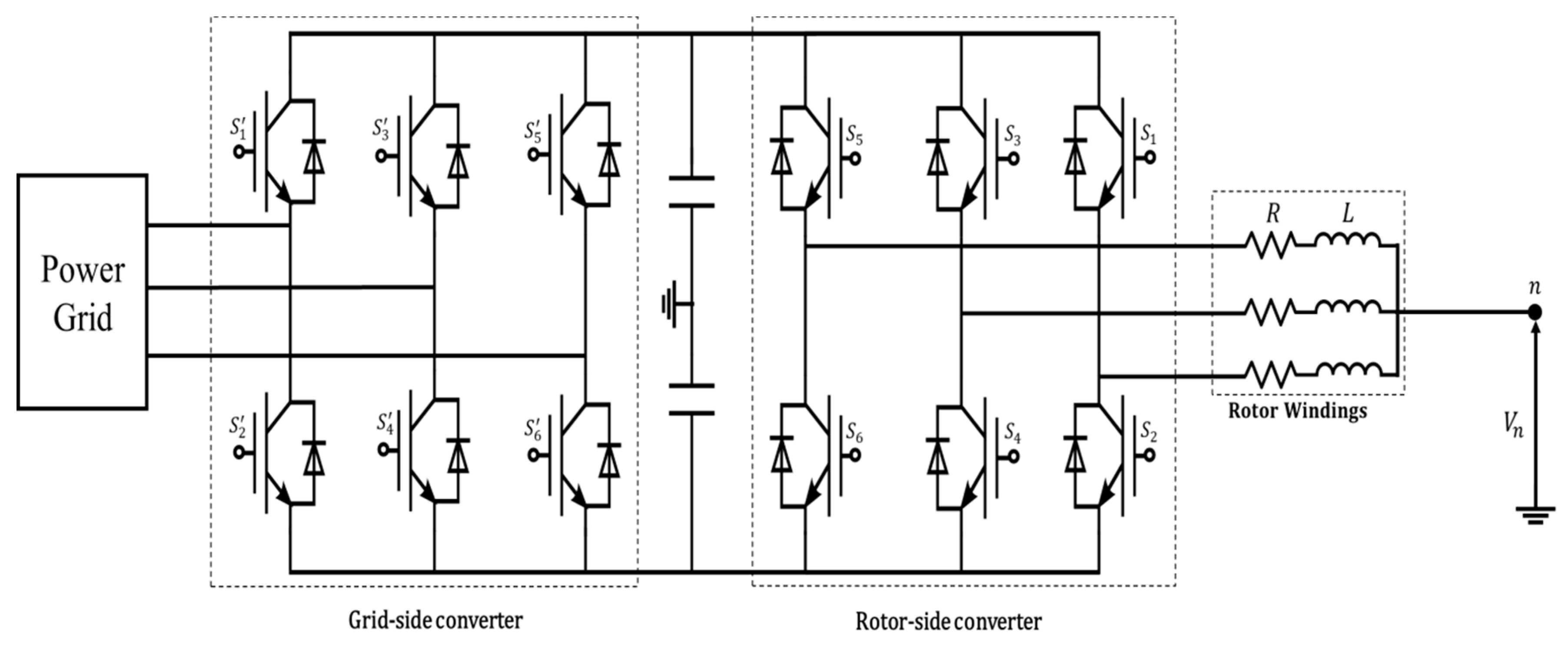
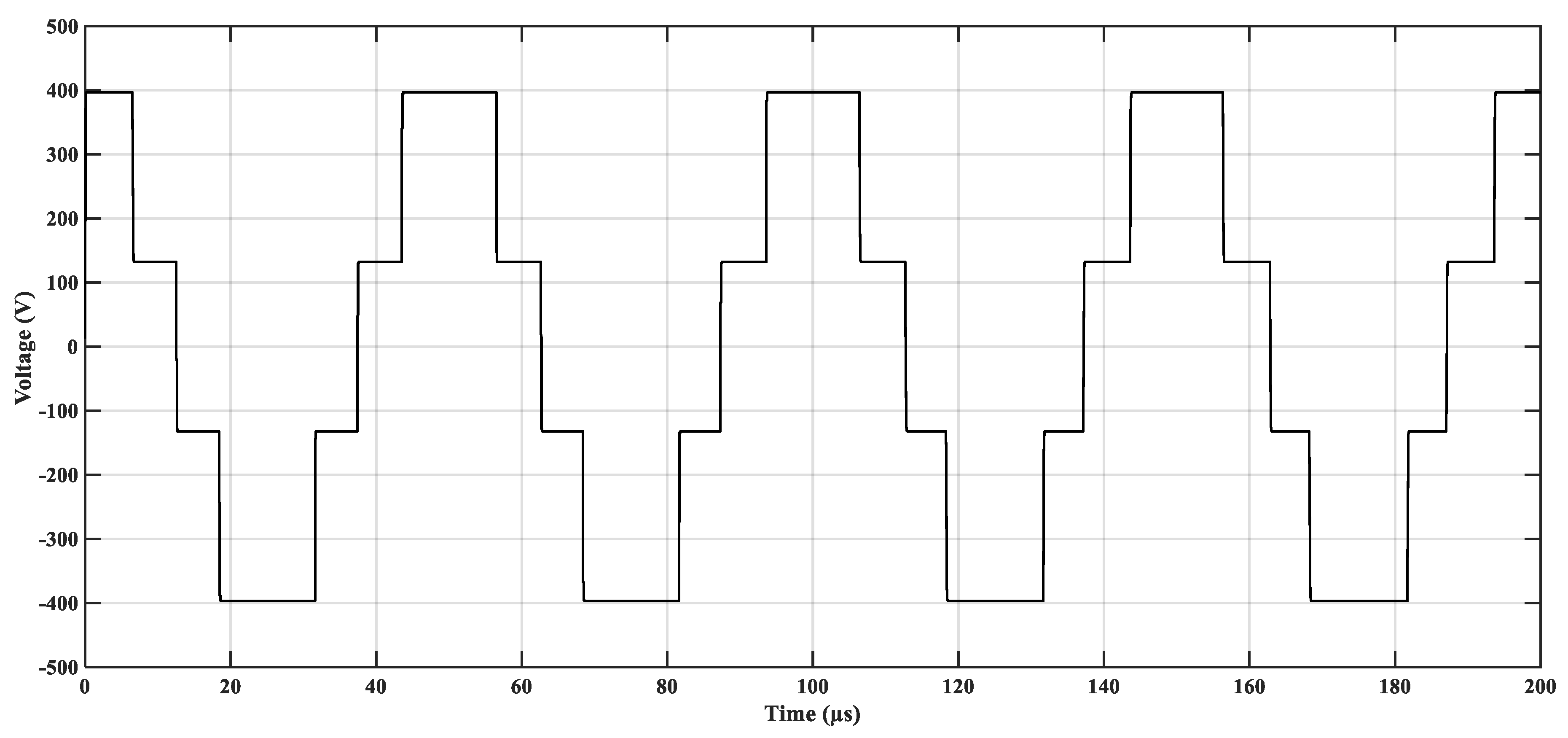
2. Common-Mode Voltage

For balanced three-phase systems, the neutral point voltage (the summation of the sinusoidal phase shifted voltages) instantaneously equals zero. On using the PWM converter in the DFIG, the summation is no longer equal to zero and hence the rotor neutral point has a zero-sequence voltage as shown in Figure 1. This voltage is called high-frequency CMV (neutral point voltage), Vcom. The converter output phase voltages Va, Vb, Vc are given by Equations (1)–(3) as follows [15]:
V a V n = L r d i a d t + R i a
V b V n = L r d i b d t + R i b
V c V n = L r d i c d t + R i c
By summing Equations (1)–(3) we have:
V a + V b + V c 3 V n = R ( i a + i b + i c ) + L r ( d i a d t + d i b d t + d i c d t )
Because i a + i b + i c = 0 , then the common-mode voltage is:
V c o m = V n = V a + V b + V c 3

3. Doubly-Fed Induction Generator Stray Circuit

The stray capacitances of the DFIG result in the development of the CMV between the rotor neutral point and the ground. There are four basic conducting parts in the generator: the rotor windings, stator windings, stator frame and rotor frame. Hence, there are several stray capacitances in DFIG, as shown in Figure 2 and Figure 3: rotor winding to rotor frame capacitance ( C w r ), rotor winding to stator frame capacitance ( C w f ), rotor frame to stator frame capacitance ( C r f ) and bearing capacitances ( C b 1 & C b 2 ). The stray capacitances between the stator windings and other parts are very small and can be ignored [6,16].
It is not easy to determine the exact values of stray capacitances using specific equations based on machine geometry, as reported before [15]. This is because the complex structure of DFIG and the analytical methods may produce calculation errors. The accurate values of stray capacitances of the DFIG were determined using the electromagnetic field numerical calculation based on the finite element method (FEM) [6]. Therefore, the values obtained before [6], as given in Table 1 for a 1.5 MW DFIG, will be used in the present work.
As shown in Figure 2, the inner raceway of the bearing has the same potential as the rotor frame being tied to the shaft. Also, the outer raceway of bearing has the same potential as the stator frame since it is connected to the stator end cover and the ground. The bearing balls separate the outer raceway and inner raceway with a lubricating oil-film surrounding the balls. As the oil-film is an insulating medium, capacitances C b 1 and C b 2 are formed between the balls and the inner and outer raceways, respectively, Figure 2. Figure 3 shows the capacitances C b 1 and C b 2 which are approximately equal ( C b 1 C b 2 ). These capacitances usually change with generator speed, temperature, and the load [6].

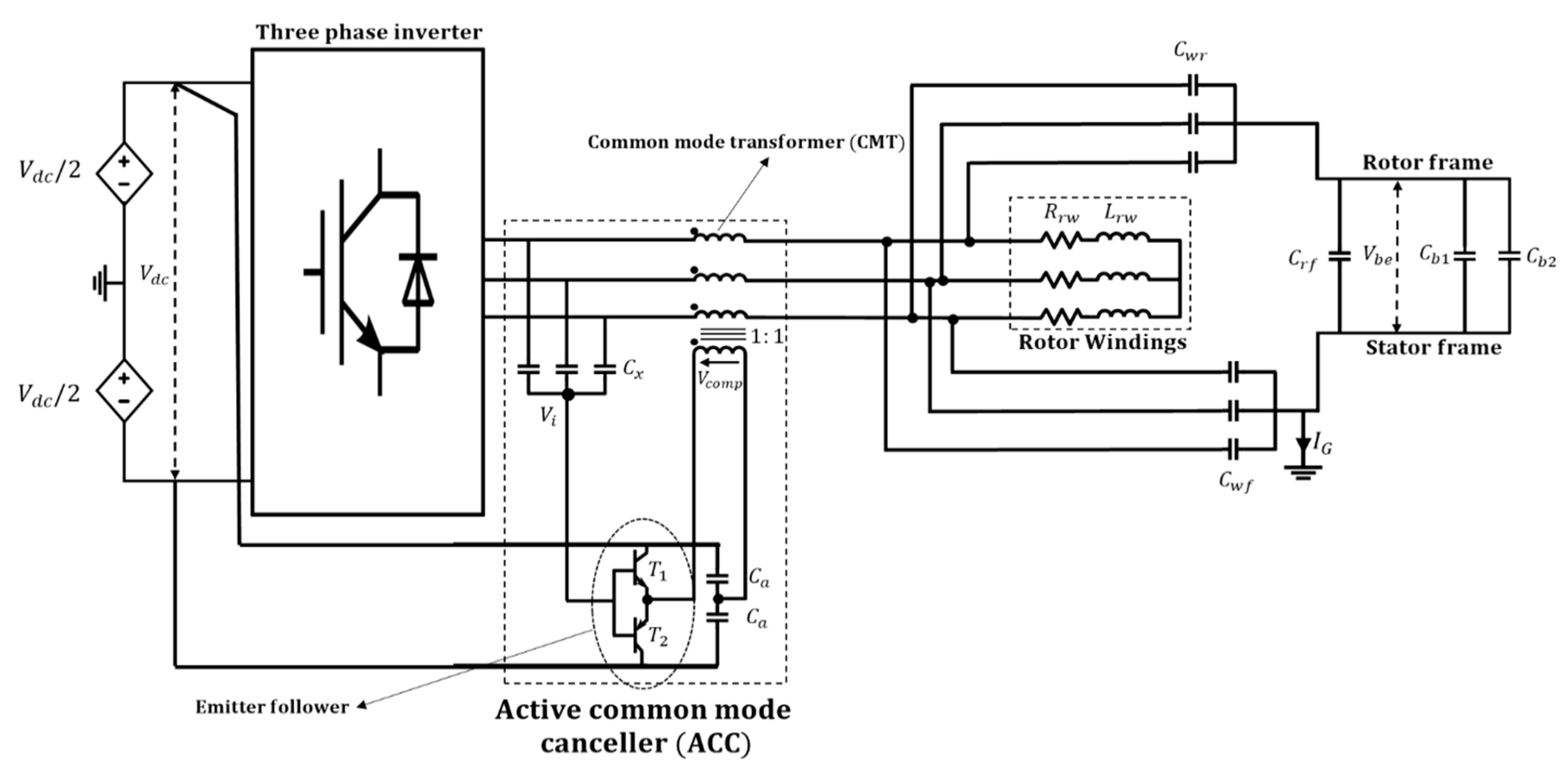
4. Active Common-Mode Voltage Canceler

4.1. Operation of Active Common-Mode Voltage Canceler (ACMVC)

A three-phase PWM converter using IGBT switches is connected to the rotor of DFIG through the proposed ACMVC as shown in Figure 3. The DC link voltage V d c is split into two sources as shown in Figure 3. Switches S 1 to S 6 of the converter in Figure 1 are turned on/off by the PWM technique. A three-phase Y-connected capacitor bank ( C x ) is used to detect the CMV at converter terminals and to feed it to the proposed canceler. The latter consists of a common-mode transformer (CMT) and a push–pull emitter follower (EF) using transistors T1 and T2 with a complementary symmetry. In addition, two capacitors ( C a ) are connected to the terminals of the DC link to prevent flow of excessive DC current in the CMT to avoid stressing the EF and the possible failure of its transistors T1 and T2. The DC link voltage serves as a DC power supply of the EF circuit. The EF circuit, along with the three capacitors C x , acts as a voltage-controlled voltage source with a unity voltage gain as shown in Figure 3. The same detected CMV is provided by the EF to the CMT as a compensating voltage ( V c o m p ). The windings’ polarity of the CMT is marked by dots as shown in Figure 3. As a result, the polarity of CMT secondary-windings is opposite to that of the CMV generated by the converter. Consequently, the CMV is decreased significantly with a very small value of CMC.

4.2. Design Parameters of the ACMVC

The parameters of the ACMVC include the capacitance values of the Y-connected capacitors ( C x ) and the two DC side capacitors ( C a ) as well as the CMT and the EF components.
The Y-connected capacitors ( C x ) are connected to the converter terminals to measure the converter CMV in the simulation model. In order to make a direct connection between C x and the converter terminals without causing any problem, the value of C x is approximately equal to the capacitance of the converter IGBT, which is equal to 180 pF.
On the other hand, the capacitance value of capacitors ( C a ) has to be as large as possible to avoid the voltage variation of the neutral point and to ensure the stability of the compensating voltage. This is why the value of the capacitance C a is selected to be 1.2 µF.
In the CMT, four ferrite cores used. The CMT should be designed to avoid any magnetic saturation. Consequently, the product of the number of turns (N) and the number of cores (M) should satisfy the following relation [1]:
V d c T 8 A c B c > N M
where:
  • T is the PWM period of the converter = 50 µs.
  • Vdc is the DC link voltage of the converter = 800 V.
  • Ac is the effective cross section area of the core = 235 mm2.
  • Bc is saturation magnetic flux density = 0.43 T.
The value of M is 4 and the number of turns per core N is selected 22 turns [1]. Consequently, the magnetizing inductance of CMT can be calculated as follows [1]:
L c m = M   * N 2 * A L   ( H )
where:
  • AL is the specific inductance of the magnetic core = 13.2 ∗ 10−6 H.
Hence, Lcm = 4 * 222 * 13.2 * 10−6 = 25.6 mH.
The voltage-controlled voltage source including the EF circuit along with the three capacitors Cx requires the following design considerations:
(1)
A high-input impedance to minimize the capacitance of Cx.
(2)
A low-output impedance for eliminating any current effect on the compensating voltage (Vcomp).
(3)
A wide-frequency bandwidth of up to several megahertz.
These requirements are satisfied by the EF using two complementary transistors. Table 2 gives the maximum ratings of the transistors, which are operated in the active region.

5. Simulation Results

In the following subsections we will discuss the effect of the integration of the ACMVC on the common-mode voltage, the common-mode current and the shaft voltage. The switching patterns of the voltage at phase-a of the machine side converter as shown in Figure 1 are given in Figure 4 with a zoom view at a switching point. Also, the currents flowing through switches S 5 and S 3 of the machine side converter as shown in Figure 1, are presented in Figure 5 for a better description of the voltages and current of the PWM converter. In addition, the effect of the variation of the rise time of the CMV on the peak value of common-mode current peak will be presented. The step time of the simulation is 0.01 µs.

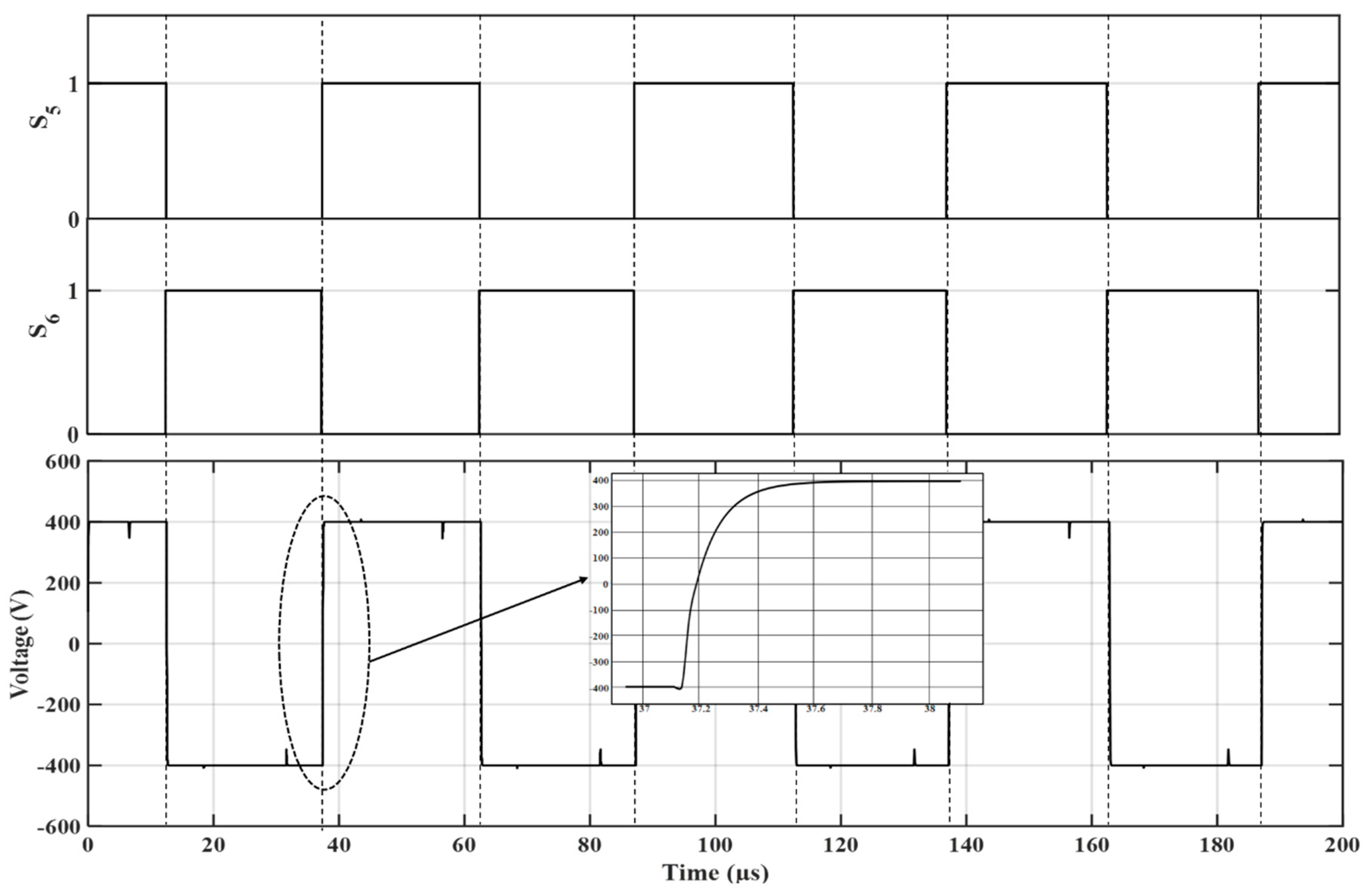
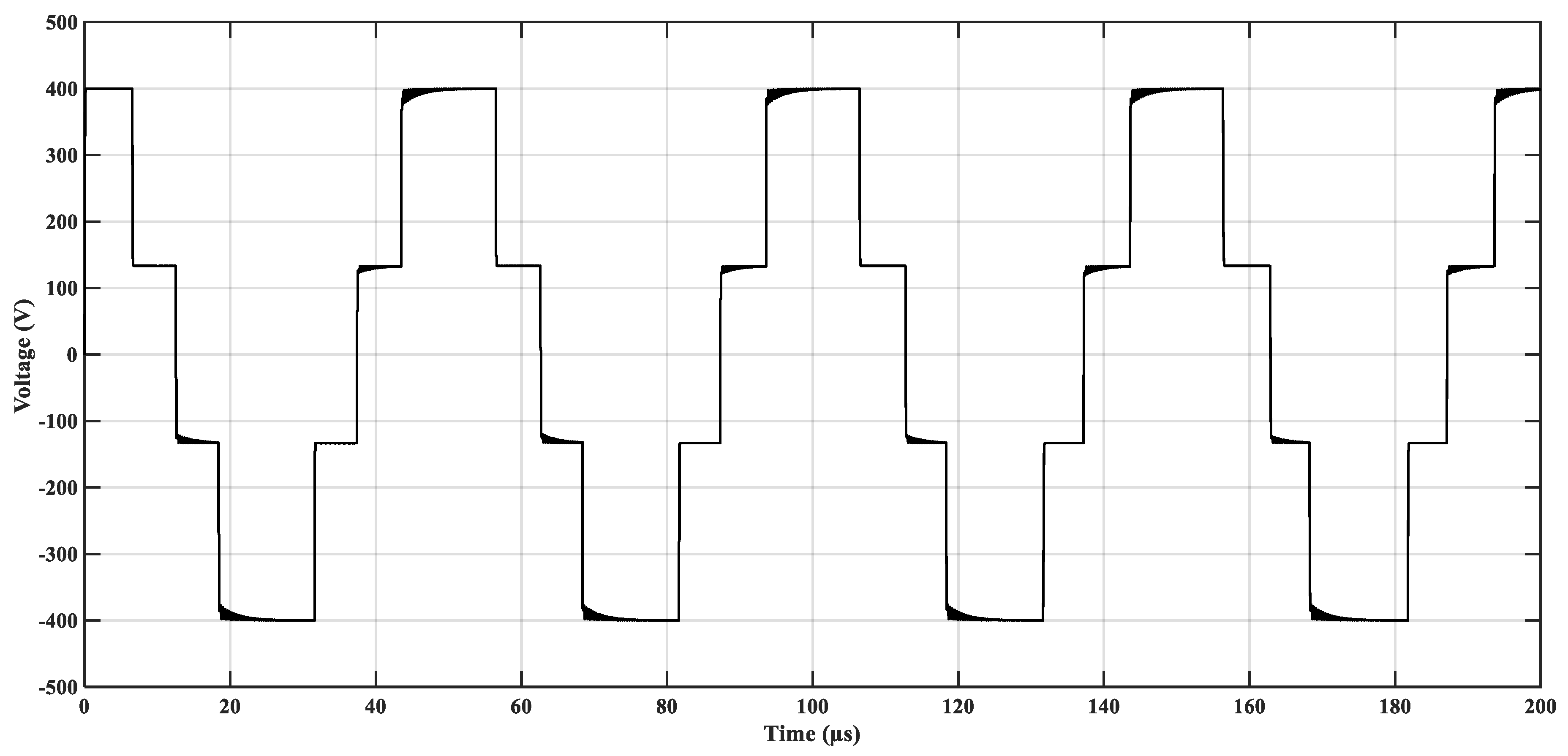
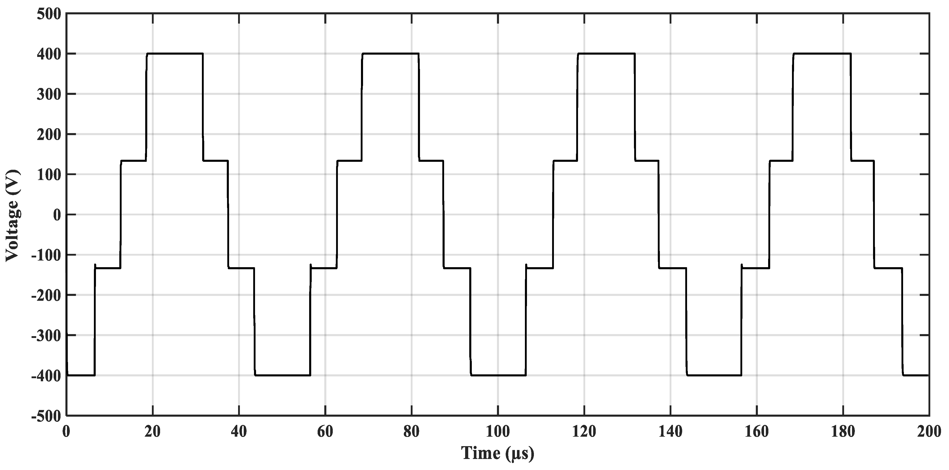
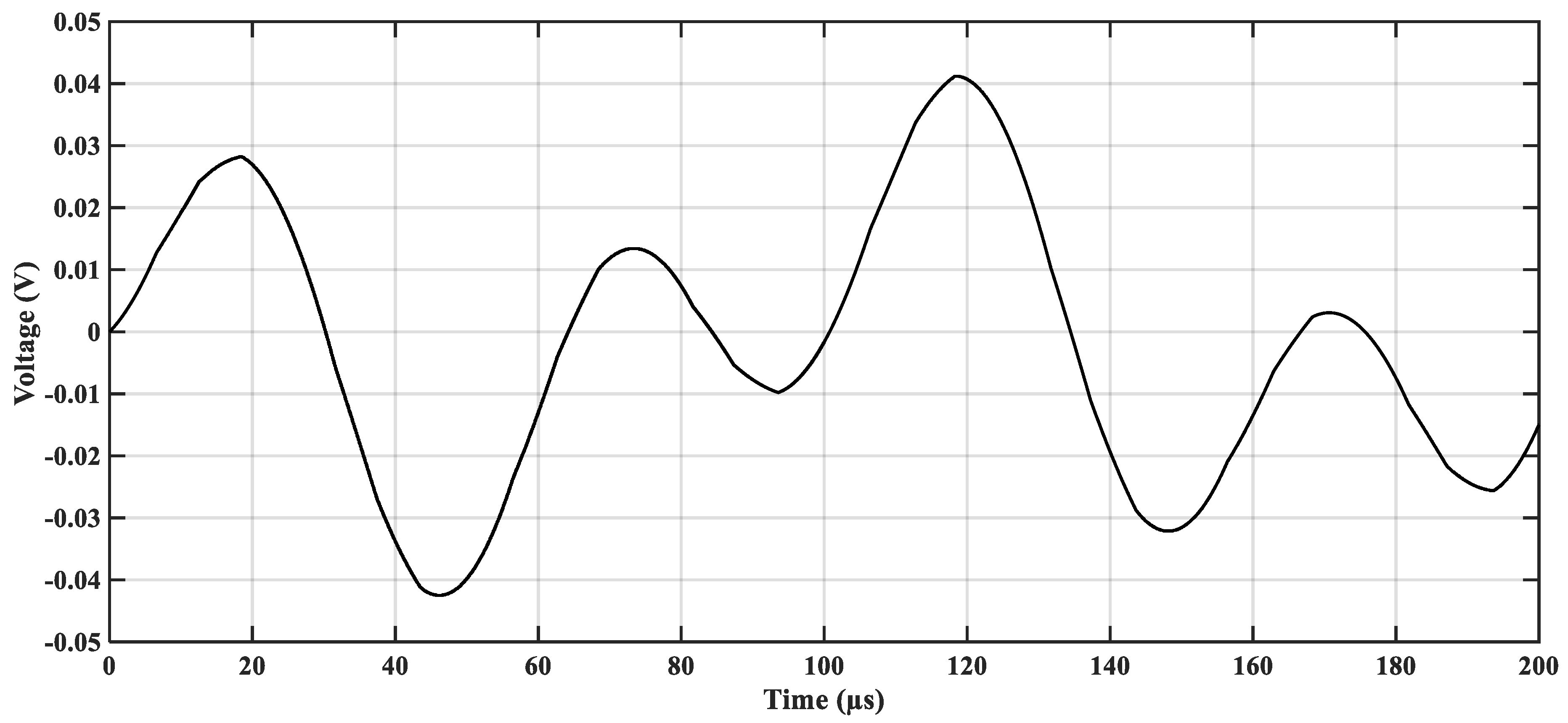
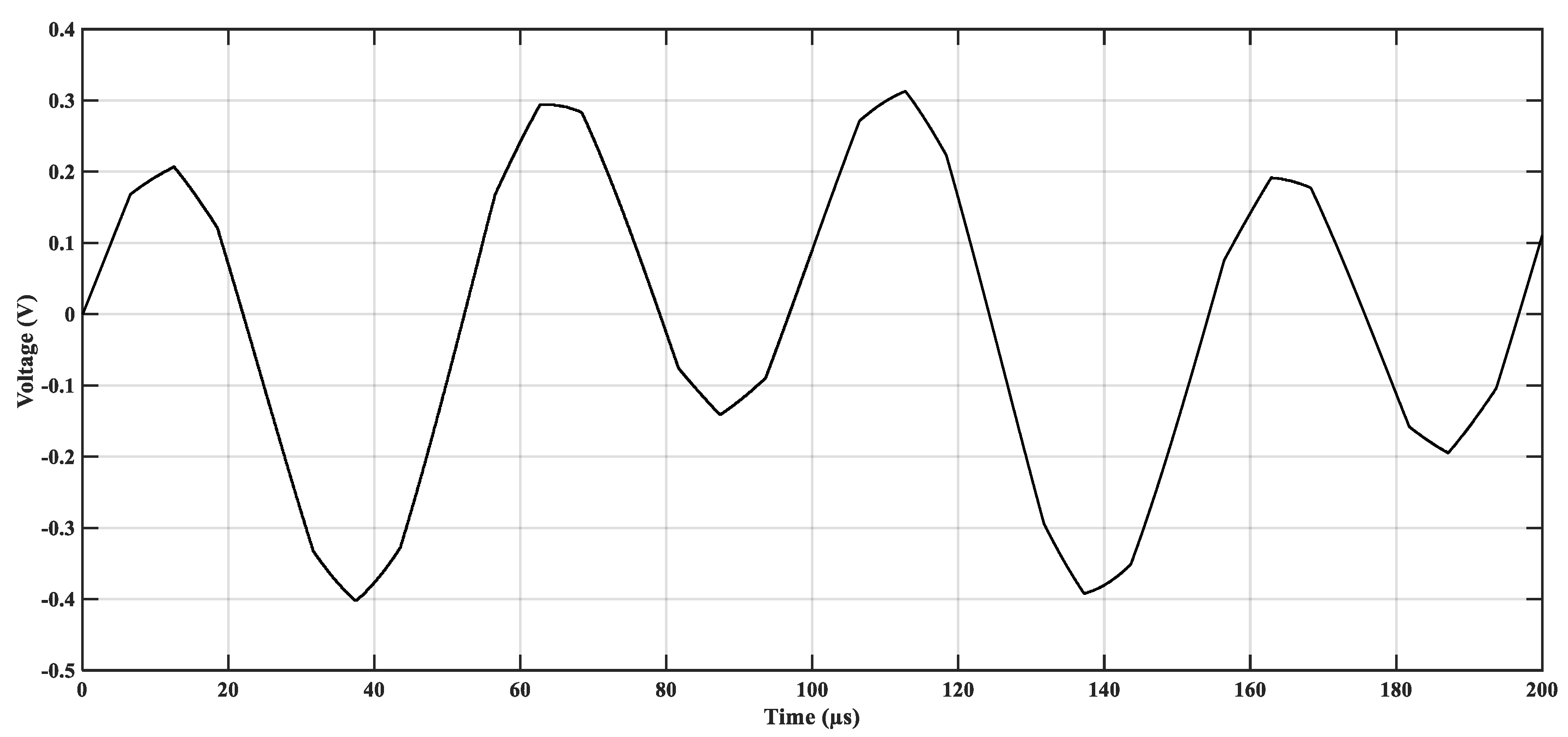
5.1. Effect of the Proposed ACMVC on the Common-Mode Voltage

The common-mode voltage is measured in the simulation model of the proposed ACMVC at the converter terminals, as shown in Figure 3. Figure 6, Figure 7 and Figure 8 show the waveforms of the common-mode voltage without the ACMVC, the compensating voltage of common-mode transformer and the common-mode voltage with the ACMVC, respectively. It is quite clear that the peak value of common-mode voltage drops from 0.4 kV in Figure 6 to 0.04 V in Figure 8, which confirms the capability of the ACMVC in suppressing the CMV significantly.

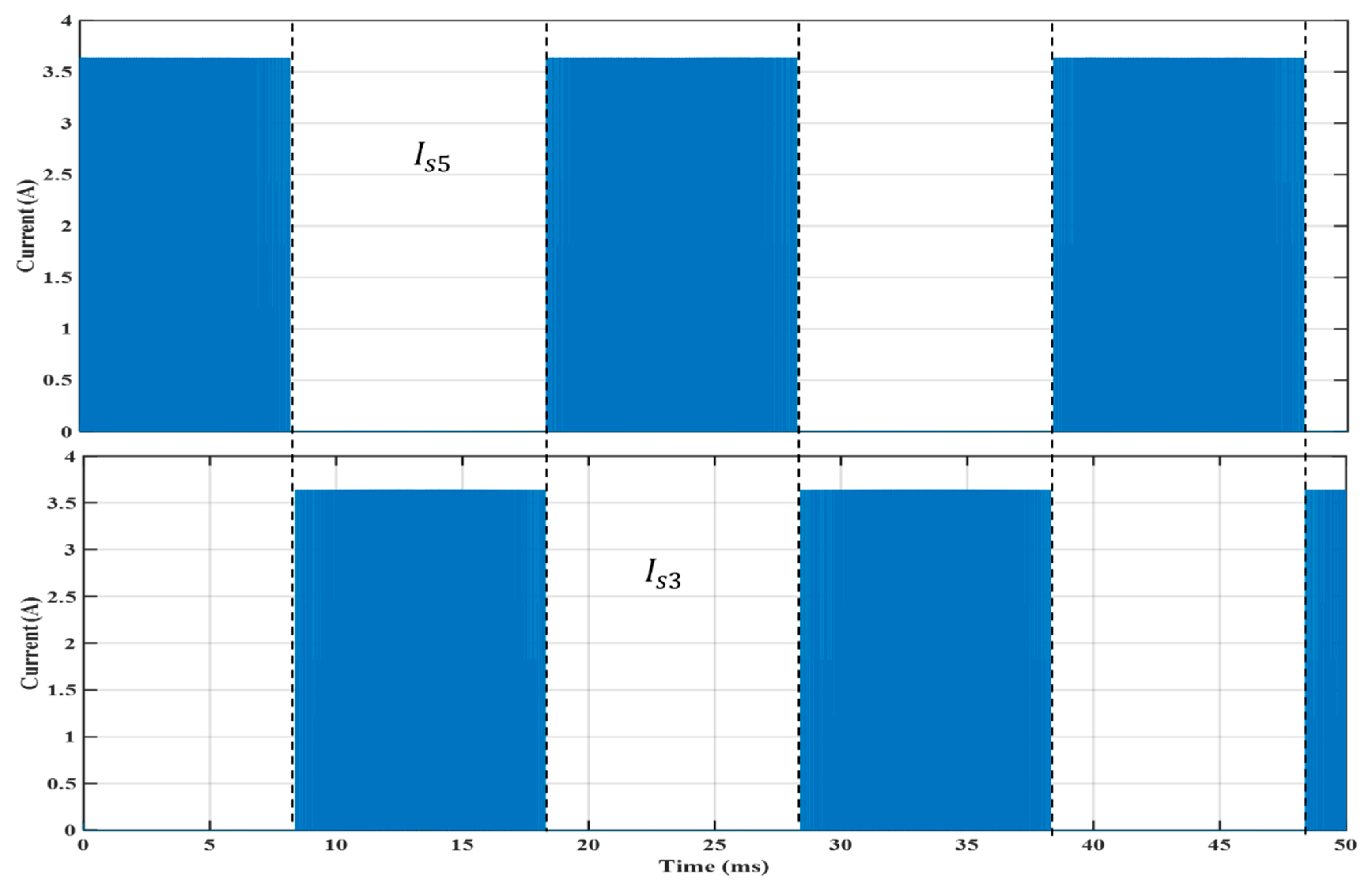
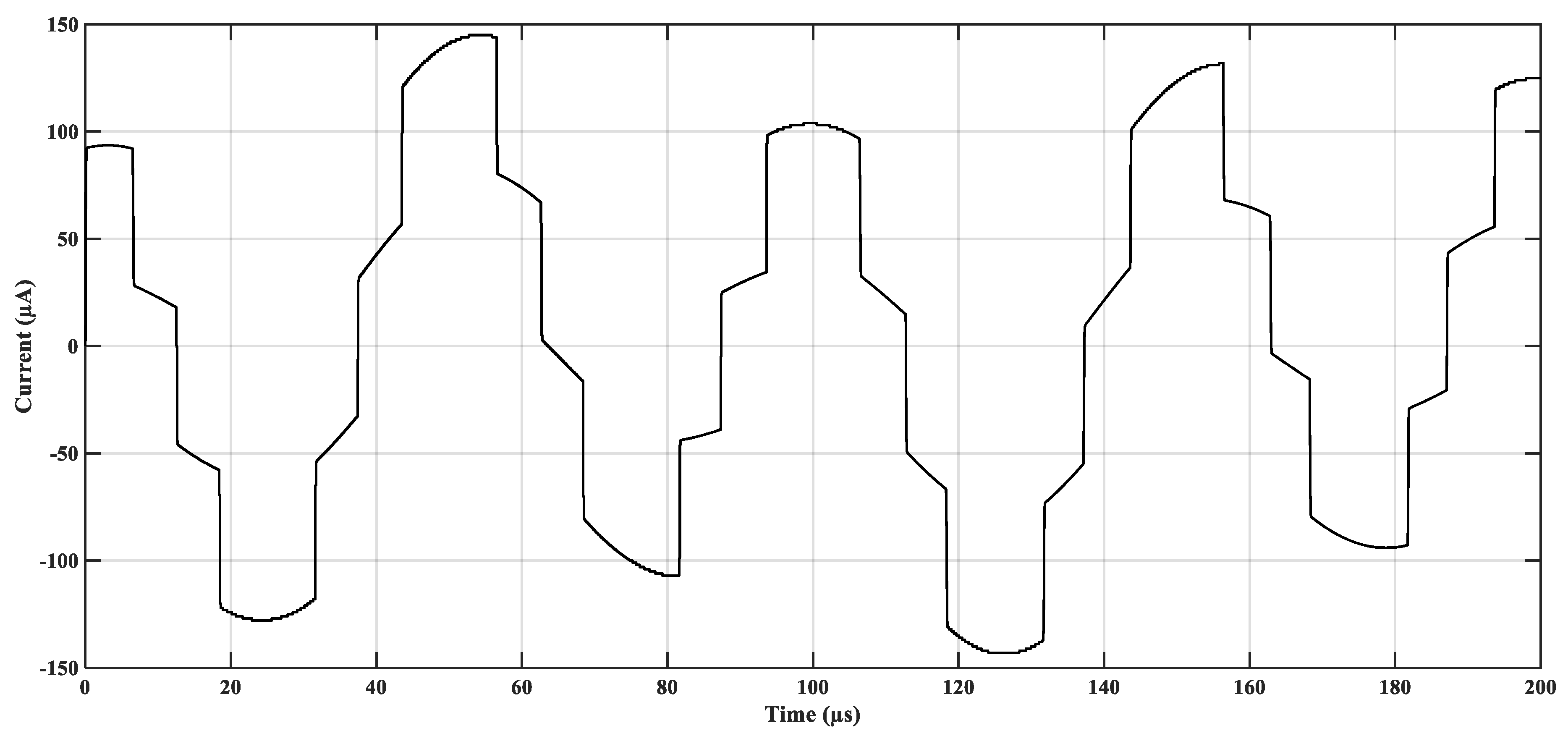
5.2. Effect of the Proposed ACMVC on the Common-Mode Current

The common-mode current ( I G ) is measured in the simulation model of the proposed ACMVC between the stator frame of the generator and the ground, as shown in Figure 3. Figure 9 and Figure 10 show the waveforms of the common-mode current without and with the ACMVC, respectively. It is quite clear that the peak value of common-mode current drops from 40 A in Figure 9 to about 145 µA in Figure 10, which confirms the capability of the ACMVC in suppressing not only the common-mode voltage but also the common-mode current.

5.3. Effect of the Proposed ACMVC on Bearing Voltage

The bearing voltage ( V b e ) is measured in the simulation model of the proposed ACMVC between the rotor and stator frames of the generator, as shown in Figure 3. Figure 11 and Figure 12 show the waveforms of the bearing voltage without and with the ACMVC, respectively. It is quite clear that the peak value of V b e drops from 400 V in Figure 11 to about 0.3 V in Figure 12, which confirms the capability of the ACMVC in remarkable suppression of the bearing voltage. This relieves the bearing from the stress imposed on it due to the CMV with a subsequent drop of the bearing current and associated breakdown of the oil-film lubricating the balls of the bearing. This will enlarge the lifetime of the balls. This will open the way for the technological development of manufacturing wind turbine DFIG by supporting them with the proposed ACMVC. This extends the lifetime of the generator’s bearing and hence the lifetime of the generator itself.

5.4. Relationship between CMC and Rise Time of CMV

The high-frequency leakage current to the ground (CMC) is influenced by the rise time of the CMV generated by PWM converter. Figure 13 shows a relationship between the rise time ( τ r ) of the CMV waveform and the peak value of CMC. With the increase of the rise time of the CMV by 10 times, the peak value of the CMC drops considerably to about 1/10 of its original value. Such a relationship will help in limiting the rate of voltage rise at the converter terminals due the CMV, with a subsequent reduction of the stress imposed on the bearing to extend its insulation lifetime.

6. Conclusions

An active common-mode voltage canceler is developed, and is employed to cancel the CMV produced by a PWM three-phase converter connected to the rotor winding of a DFIG. Simulation results confirmed that the proposed ACMVC is capable of the perfect suppression of the CMV. Consequently, the produced common-mode current (leakage current to the ground) is decreased with a subsequent decrease of the voltage stress imposed on the rotor bearings and hence extends its insulation lifetime. A relationship between the rise time of the CMV waveform and the peak value of CMC is formulated to help reduce the stress imposed on the bearings.

Author Contributions

Data curation, A.S.Z.; formal analysis, A.S.Z.; investigation, A.S.Z.; methodology, A.S.Z.; project administration, M.A.-S.; software, A.S.Z.; supervision, M.A.-S. and M.A.; visualization, A.S.Z.; writing—original draft, A.S.Z.; writing—review and editing, M.A.-S. and M.A.

Acknowledgments

The authors are beholden to the Ministry of Higher Education (MOHE), Egypt for supporting this work and appreciation to the Egypt-Japan University of Science and Technology (E-JUST) for providing tools and guidance to complete this research. The authors would also like to thank Hideaki Fujita from Tokyo Institute of Technology, Tokyo, Japan, for his support, guidance and valuable comments.

Conflicts of Interest

The authors declare no conflict of interest.

References

  1. Ogasawara, S.; Ayano, H.; Akagi, H. An active circuit for cancellation of common-mode voltage generated by a PWM inverter. IEEE Trans. Power Electr. 1998, 13, 835–841. [Google Scholar] [CrossRef] [Green Version]
  2. Ogasawara, S.; Akagi, H. Circuit configurations and performance of the active common-noise canceler for reduction of common-mode voltage generated by voltage-source PWM inverters. In Proceedings of the 2000 IEEE Industry Applications Conference. Thirty-Fifth IAS Annual Meeting and World Conference on Industrial Applications of Electrical Energy (Cat. No.00CH37129), Rome, Italy, 8–12 October 2000; pp. 1482–1488. [Google Scholar]
  3. Jabbar, M.A.; Azizur Rahman, M. Radio Frequency Interference of Electric Motors and Associated Controls. IEEE T. Ind. Appl. 1991, 27, 27–31. [Google Scholar] [CrossRef]
  4. Murai, Y.; Kubota, T.; Kawase, Y. Leakage current reduction for a high-frequency carrier inverter feeding an induction motor. IEEE T. Ind. Appl. 1992, 28, 858–863. [Google Scholar] [CrossRef]
  5. Ogasawara, S.; Akagi, H. Modeling and damping of high-frequency leakage currents in PWM inverter-fed AC motor drive systems. IEEE T. Ind. Appl. 1996, 32, 1105–1114. [Google Scholar] [CrossRef] [Green Version]
  6. Liu, R.; Ma, X.; Ren, X.; Cao, J.; Niu, S. Comparative Analysis of Bearing Current in Wind Turbine Generators. Energies 2018, 11, 1305. [Google Scholar] [CrossRef]
  7. Ruckert, B.; Hofmann, W. Enhanced direct power control of doubly fed induction generators. In Proceedings of the 14th International Power Electronics and Motion Control Conference EPE-PEMC 2010, Ohrid, Macedonia, 6–8 September 2010; pp. 27–33. [Google Scholar]
  8. Zitzelsberger, J.; Hofmann, W.; Wiese, A.; Stupin, P. Bearing currents in doubly-fed induction generators. In Proceedings of the 2005 European Conference on Power Electronics and Applications, Dresden, Germany, 11–14 September 2005; pp. 1–9. [Google Scholar]
  9. Adabi, M.E.; Vahedi, A. A survey of shaft voltage reduction strategies for induction generators in wind energy applications. Renew. Energy 2013, 50, 177–187. [Google Scholar] [CrossRef]
  10. Chen, S.; Lipo, T.A.; Fitzgerald, D. Source of induction motor bearing currents caused by PWM inverters. IEEE Trans. Energy Convers. 1996, 11, 25–32. [Google Scholar] [CrossRef]
  11. Busse, D.; Erdman, J. System electrical parameters and their effects on bearing currents. IEEE Trans. Ind. Appl. 1997, 33, 577–584. [Google Scholar] [CrossRef] [Green Version]
  12. Busse, D.; Erdman, J.; Kerkman, R.J.; Schlegel, D.; Skibinski, G. Bearing currents and their relationship to PWM drives. IEEE Trans. Power Electr. 1997, 12, 243–252. [Google Scholar] [CrossRef] [Green Version]
  13. Garcia, A.; Holmes, D.G.; Lipo, T.A. Reduction of Bearing Currents in Doubly Fed Induction Generators. In Proceedings of the 2006 IEEE Industry Applications Conference Forty-First IAS Annual Meeting, Tampa, FL, USA, 8–12 October 2006; pp. 84–89. [Google Scholar]
  14. Alewine, K.; Chen, W. A review of electrical winding failures in wind turbine generators. IEEE Electr. Insul. Mag. 2012, 28, 8–13. [Google Scholar] [CrossRef]
  15. Whittle, M.; Trevelyan, J.; Tavner, P.J. Bearing currents in wind turbine generators. J. Renew. Sustain. Energy 2013, 5. [Google Scholar] [CrossRef]
  16. Muetze, A.; Binder, A. Calculation of motor capacitances for prediction of the voltage across the bearings in machines of inverter-based drive systems. IEEE Trans. Ind. Appl. 2007, 43, 665–672. [Google Scholar] [CrossRef]
Figure 1. Three-phase pulse-width modulated power converter connecting rotor winding to power grid.
Energies 12 00691 g001
Figure 2. Physical construction of the doubly-fed induction generator showing different stray capacitances.
Energies 12 00691 g002
Figure 3. Proposed active common-mode voltage canceler connected between the rotor winding and AC–DC converter of DFIG.
Energies 12 00691 g003
Figure 4. Switching patterns for voltage of phase-a for the pulse-width modulated converter.
Energies 12 00691 g004
Figure 5. Currents of switches S 5 and S 3 of the PWM converter.
Energies 12 00691 g005
Figure 6. Common-mode voltage without the ACMVC.
Energies 12 00691 g006
Figure 7. Compensating voltage of common-mode transformer.
Energies 12 00691 g007
Figure 8. Common-mode voltage with the ACMVC.
Energies 12 00691 g008
Figure 9. Common-mode current without the ACMVC.
Energies 12 00691 g009
Figure 10. Common-mode current with the ACMVC.
Energies 12 00691 g010
Figure 11. DFIG bearing voltage without the ACMVC.
Energies 12 00691 g011
Figure 12. DFIG bearing voltage with the ACMVC.
Energies 12 00691 g012
Figure 13. Relationship between the rise time of common-mode voltage and peak value of common-mode current.
Energies 12 00691 g013
Table 1. Stray capacitances for a 1.5 MW DFIG.
Capacitance SymbolCwrCwfCrfCb1&Cb2
Value (nF)152.30.0273.30.12
Table 2. Absolute maximum ratings of Emitter Follower Transistors.
ModelPBHV9560ZPBHV8560Z
Maximum collector-base voltage VCBO (V)−600600
Maximum collector-emitter voltage VCEO (V)−600600
Maximum collector current IC (DC) (A)−0.50.5
Maximum power dissipation PC (W) (Tamb ≤ 25 °C)0.650.65

