Article

A Non-Uniform Transmission Line Model of the ±1100 kV UHV Tower

1
State Grid Corporation of China, Beijing 100000, China
2
Department of Electrical Engineering, Zhejiang University, Hangzhou 310058, China
*
Author to whom correspondence should be addressed.
Energies 2019, 12(3), 445; https://doi.org/10.3390/en12030445
Submission received: 30 December 2018 / Revised: 28 January 2019 / Accepted: 28 January 2019 / Published: 30 January 2019
(This article belongs to the Special Issue DC and AC Overhead Transmission Lines from Low to Extra-High Voltages)

Abstract

:
The modeling of the Ultra-High Voltage (UHV) tower plays an important role in lightning protection analysis of transmission lines because the model used will directly affect the reliability of the results. Moreover, the higher the voltage level is, the more prominent the impact becomes. This paper first analyzes the inapplicability of the Hara multi-segment multi-surge impedance model for the ±1100 kV UHV towers, and then builds a non-uniform transmission line model of the tower. Secondly, the multi-segment multi-surge impedance model is used to study the influence of the tower’s spatial structure changes on its electromagnetic transient characteristics. It is concluded that the more accurately the nominal height of the tower is modeled, the more accurately its electromagnetic transient response is reflected. Finally, the lightning electromagnetic transient responses of the tower with the non-uniform transmission line model and with the multi-segment multi-surge impedance model are compared and analyzed, which shows that the non-uniform transmission line model is more in line with the actual situation under the lightning strikes.

1. Introduction

Years of experience in line operations at home and abroad have shown that line trip-out accidents caused by lightning strikes account for 40% to 70% of the total line trip-out accidents [1]. Trip-out accidents are particularly prominent in areas with complex topography, high soil resistivity or high lightning density. It can be seen that lightning strikes are still the main threat to the safe and reliable operation of the transmission lines [2,3]. Due to the complexity of the terrain over long distance transmission, large span UHV towers are often required. The UHV tower is subjected to a higher level of overvoltage when struck by lightning than the ordinary height tower. And the insulation level also requires more. Therefore, the accuracy of the modeling directly affects the reliability of the lightning protection analysis results of the transmission lines. At present, the multi-surge impedance model is commonly used in engineering. It can meet the demand of the calculation accuracy of the ordinary height tower, but cannot meet the requirements for the UHV tower.
When the influence of the earth on the impedance of the vertical conductor is considered, the surge impedance at different position of the vertical conductor is unequal. The multi-surge impedance model is based on this theory [4]. The tower model commonly used in engineering is typically the multi-surge impedance model proposed by Hara et al. [5]. In this multi-surge impedance model, the main body of the tower is divided into several parts with the cross arms as nodes, and each part is equalized by a surge impedance. With the increase of the transmission voltage level, the height of the tower also increases in order to meet the insulation requirements. The nominal height becomes the main part of the tower, so if only one surge impedance is used to model the nominal height, the influence of the changes in the spatial structure on the tower’s electromagnetic transient responses cannot be accurately reflected.
In modelling the UHV tower, based on the Hara multi-surge impedance model, reference [6] divides the nominal height into 11 segments to study the influence of the tower structure’s changes on its lightning transient characteristics. In [7], the formula for calculating the multi-wave impedance of the tower is developed by the theory of biconical antenna and electromagnetic field simulation. In [8], the non-uniform transmission line model of the tower is derived based on the theory of the biconical antenna, in which the mutual coupling between different conductors of the tower is considered. In [9], the non-uniform transmission line model of the composite tower is established and the distributed parameters of the metal part are also derived based on the theory of biconical antenna. So far there is little literature about the non-uniform transmission line model of the tower and its applicability in the UHV towers.
One objective of this paper is to simplify the non-uniform transmission line model for applications in real engineering. The other objective is to study the applicability of the non-uniform transmission line model in lightning transient analysis for ± 1100 kV UHV tower. The contributions of this paper are summarized as follows:
(1)
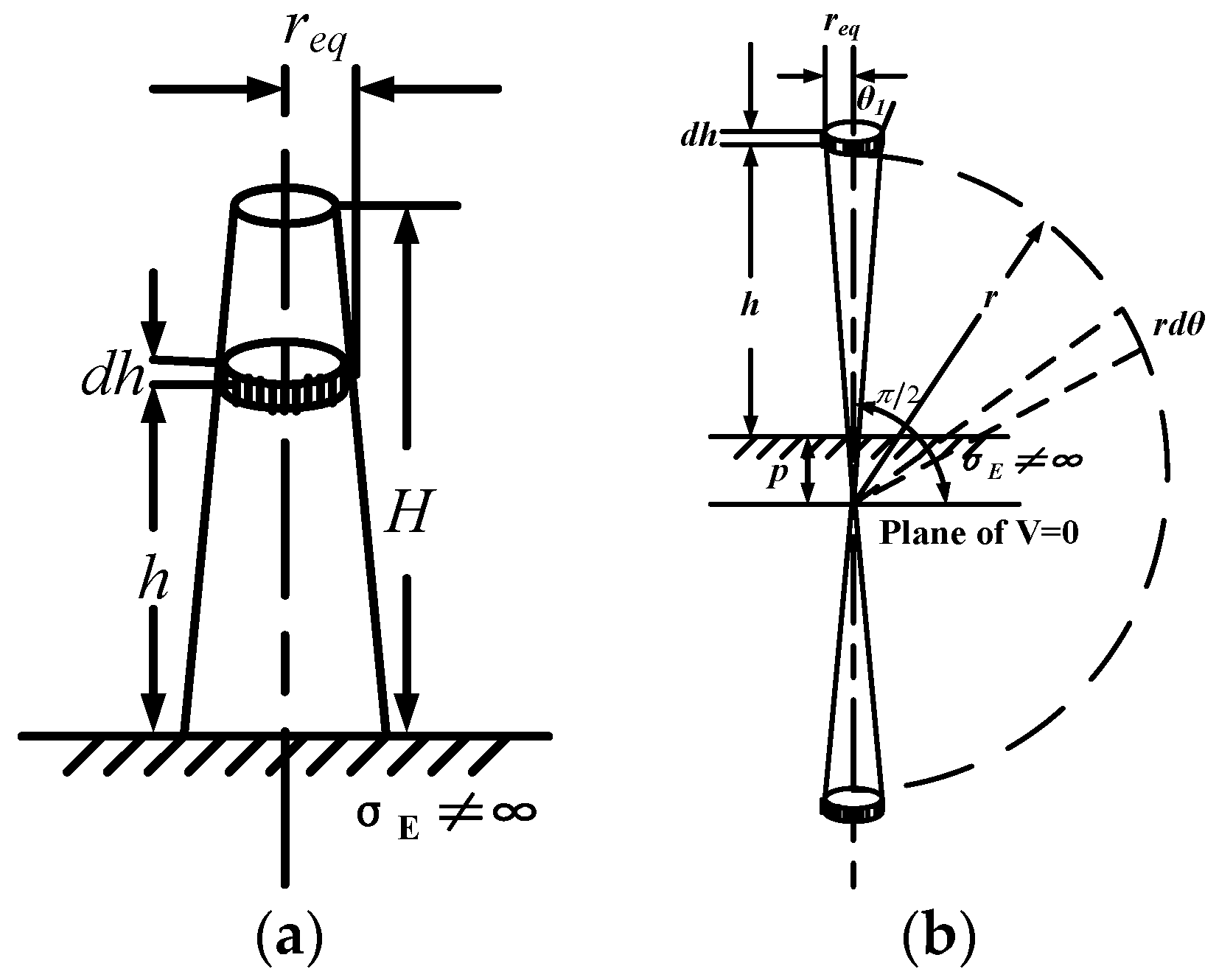
An approach to simplify the non-uniform transmission line model is proposed in this paper. The vertical parts of the tower are equalized to a single conductor system and its non-uniform distributed parameters are derived based on the theory of the biconical antenna; and the horizontal cross-arms are modeled as surge impedances since they are parallel to the ground.
(2)
The influence of the tower’s spatial structure changes on its electromagnetic transient response is studied. It is concluded that the more accurately the nominal height of the tower is modeled, the more accurately its electromagnetic transient response is reflected.
(3)
The applicability of the non-uniform transmission line model in lightning transient analysis is studied. Through comparing the lightning electromagnetic transient responses with the non-uniform transmission line model and with the multi-segment multi-surge impedance model, the applicability of the non-uniform transmission line model is verified.
This paper is organized as follows: in Section 2, the multi-surge impendence model of the tower is introduced. In Section 3, based on the theory of biconical antenna, the non-uniform transmission line model of the tower is developed. In Section 4, the influence of the tower’s spatial structure changes on its electromagnetic transient response is studied by segmenting the nominal height into several parts firstly; and then the electromagnetic transient responses with the multi-segment multi-surge impendence model and with the non-uniform transmission line model are compared and analyzed for the validations of the proposed model. Conclusions are drawn in Section 5.

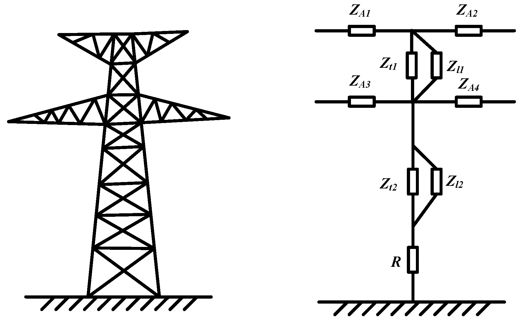
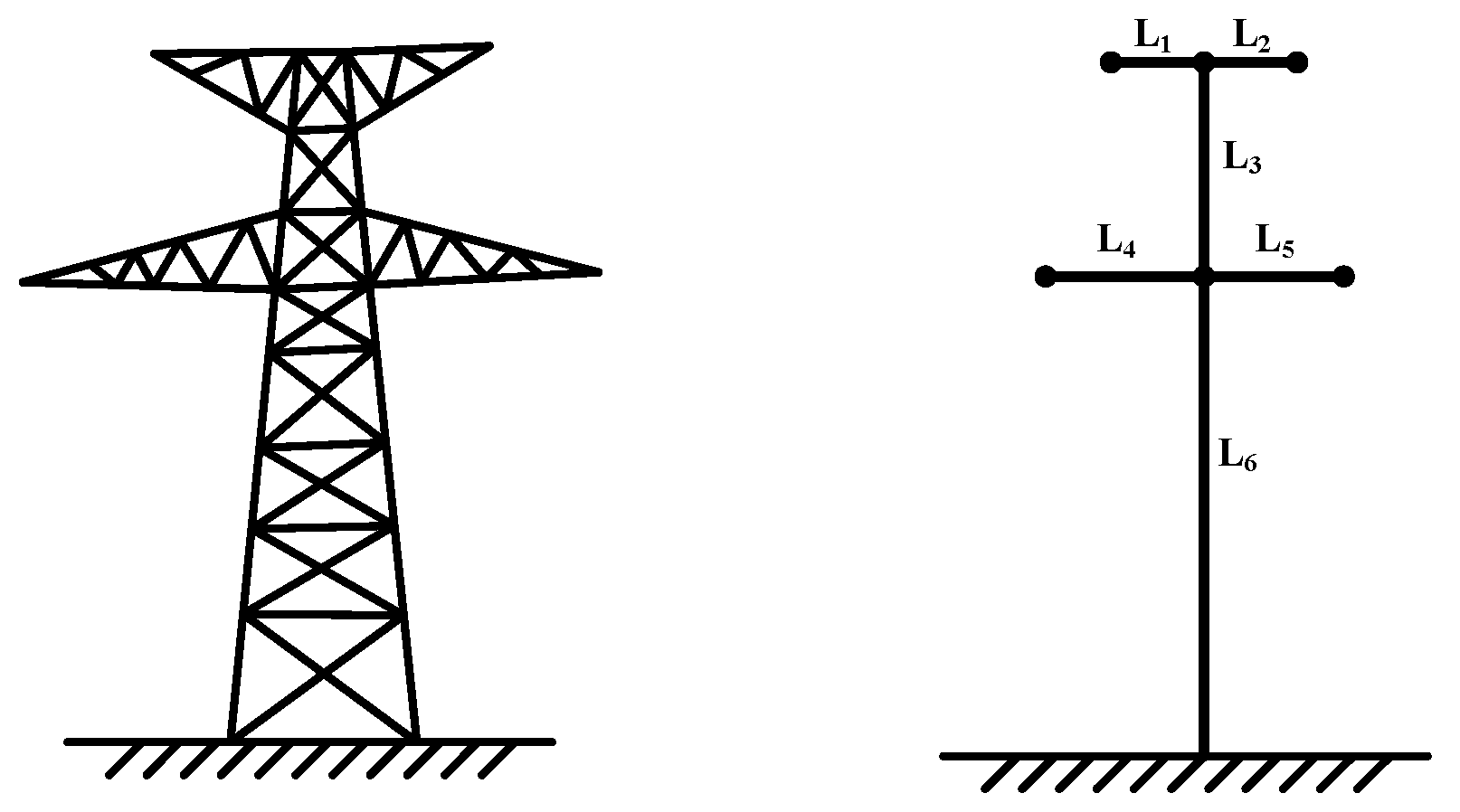
2. The Multi-Surge Impedance Model of the Tower

The multi-surge impedance model considers both the wave process in the tower and the influence of the structure and size of the tower on the value of the surge impedance, which is more in line with the actual situation than the traditional tower model. Common multi-surge impedance models include multi-layer transmission tower model, multi-layer transmission tower simplified model, Hara lossless tower model and multi-surge impedance model [5,10,11,12,13]. Among them, the surge response characteristics calculated by the Hara multi-surge impedance model are the closest to the measured values, shown in Figure 1.
The multi-surge impedance model consists of a tower body, bracings and cross arms. The Z of each part is expressed by the formula of its size and geometry. It considers the effect of the cross arms and bracings on the tower surge impedance Z, and is suitable for generalization to the transmission tower with complex structure and high height. This model is mainly used for lightning protection simulation of 500 kV transmission lines, and the surge impedance of the tower body needs to be corrected to include the influence of the initial low coupling coefficient [14].
The surge impedance of the main legs is given as follows [5]:
Z t k = 60 ( ln 2 2 h k r e k 2 ) ( k = 1 , 2 )
where, hk (k = 1, 2) and rek (k = 1, 2) are the height and the equivalent radius of the kth legs, respectively.
The surge impedance of the bracings is given by:
Z l k = 9 Z t k ( k = 1 , 2 )
And the surge impedance of the cross arms is given by the following conventional equations for horizontal conductors:
Z A k = 60 ln ( 2 h k r A k ) ( k = 1 , 2 , 3 , 4 )
where, hk is the height between the cross arm and the ground, and rAK is 1/4 of the width of the crossbar at the joint of the tower.

3. Non-Uniform Transmission Line Model of the Tower

The tower model has a great influence on the calculation of lightning overvoltage, so the accuracy of the results depends on a reasonable tower model. However, in view of the fact that the nominal height accounts for almost the entire part of the tower, modeling with only one surge impedance cannot reflect the influence of the tower’s spatial structure changes on its transient characteristics responses. Therefore, considering this deficiency of the multi-surge impedance model, this paper adopts the non-uniform transmission line model.
The tower is typically composed of several truss modules, each of which typically includes four legs that are connected by other shorter horizontal and inclined parts. The propagation of lightning current on different parts of the tower is a four-dimensional problem involving spherical waves. In [15], it is analyzed that less than 1% of the energy of the lightning current propagates along the inclined parts during propagation, and hardly propagates along the horizontal parts. Therefore, the shorter horizontal and inclined parts connecting the pillar structures may be disregarded during modelling. Only the pillar structure of the truss modules needs modelling, that is, the lightning current propagates only along the legs of the truss modules. Therefore, it can be considered that the main mode of the propagation in the tower is the transverse electromagnetic wave (TEM), based on which the surge impedance of the vertical part of the tower can be derived, and then the distributed parameters are derived. The main truss modules of the tower is usually a trapezoidal structure, and its pillar structure is composed of four non-parallel conductors. However, when calculating the parameters of the infinitesimal cylinder element, we can treat it as four parallel conductor structures. The four-conductor system of the infinitesimal cylinder element of each main truss module can be equivalent to a single-conductor structure by the clustering formula [8]:
r e q = 4 × r e n d × r c i r c 3 4
where, req is the equivalent radius of the four- conductor system, rend is the radius of a single conductor itself, and rcirc is the radius of the circumcircle of the four-conductor system, shown in Figure 2:
The formula for the radius of the circumcircle of the four-conductor system is:
r c i r c = d 2 sin ( π / 4 ) = d 2
If the truss modules are modeled as equivalent conductors of circular cross section, the tower can be modeled as an equivalent cylindrical network, shown in Figure 3.
Therefore, its electromagnetic transient response can be described by the telegraph equation as follows [16]:
u ( h , t ) h = R ( h ) i ( h , t ) + L ( h ) i ( h , t ) h i ( h , t ) h = C ( h ) u ( h , t ) h
where, L(h), R(h), and C(h) are the per-unit length inductance, resistance, and capacitance of the conductor, respectively. They varies with the height of the infinitesimal cylinder element.
The inductance L(h) consists of the following parts:
L ( h ) = L G ( h ) + L E ( h ) + L C ( h )
where, LG(h) reflects the magnetic flux in the air, LE(h) reflects that the earth is not an ideal conductive plane, and LC(h) is the inner inductance of the conductor. The resistance R(h) consists of the following parts:
R ( h ) = R E ( h ) + R C ( h )
where, RE(h) reflects the limited conductivity of the earth; RC(h) is the internal resistance of the tower, accounting for the active power loss when the electromagnetic field penetrates inside the conductor. As for the capacitance C(h), it is only composed of the geometric capacitance CG(h). It reflects the electric field effect around the conductor.

3.1. Modeling of the Horizontal Cross Arms

For the horizontal cross arm portion L1, L2, L4 and L5, each is equivalent to a single conductor and is parallel to the ground, so the parameters of the conductor are equal everywhere, and each horizontal cross arm can be modeled by one surge impendence. The surge impedance of the cross arm ZA can be calculated by the following formula [17]:
Z A = 60 ln 2 h c r o s s r
where, hcross is the height between the cross arm and the ground, and r is 1/4 of the width of the crossbar at the joint of the tower.

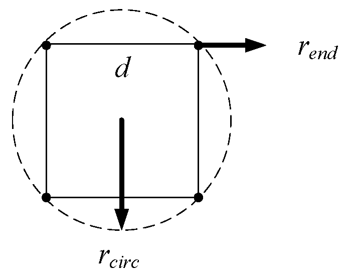
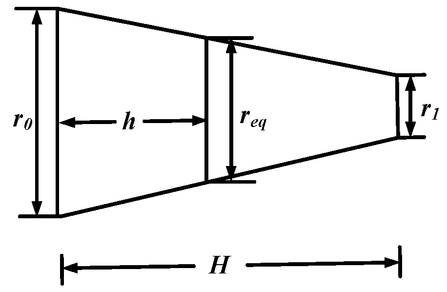
3.2. Modeling of the Vertical Main Body

For the vertical parts L3 and L6 of the tower, which are perpendicular to the ground, the parameters at different heights are different; so the vertical body of the tower is modeled as a non-uniform transmission line. Since the cross-section radius of the vertical part is much smaller than its length, the lightning wave can be regarded as a spherical wave propagating on the tower. The propagation process of the spherical wave is similar to the transverse electromagnetic wave propagation process of the double-cone antenna.
Figure 4 shows an infinitesimal element dh with a radius req and a height h above the ground on the cylindrical conductor of length H. And the propagation of the spherical wave in the infinitesimal element can be regarded as the double-cone antenna shown on the right side of Figure 4. In the figure, p is the penetration depth of the wave propagating to the earth, and can be calculated as follows [16]:
p = 1 j ω μ E σ E
where, μE and σE are the magnetic permeability and electrical conductivity of the soil, respectively, and ω is the angular frequency of the lightning current.
The main truss structure of the tower is usually trapezoidal, so the equivalent radius of the vertical infinitesimal element is obtained by the proportional method [9], shown in Figure 5:
Its equivalent radius is:
r e q = r 0 r 0 r 1 H × h
where, r0 is the equivalent radius of the tower base, r1 is the equivalent radius of the tower top, H is the height of the tower, and h is the height at which the vertical infinitesimal element is located.
The electric field and magnetic field strength of a transverse electromagnetic wave propagating in a biconical antenna can be expressed in a spherical coordinate system [18]:
{ H φ = A 0 e j β r / ( r sin θ ) E θ = μ / ε H φ E r = E φ = H θ = H r = 0 β = ω μ ε
where, A0 is the vector magnetic position, β is the phase constant, μ and ε are magnetic permeability and dielectric constant of the medium above the ground plane respectively. Hr, Hθ, Hφ and Er, Eθ, Eφ refer to the magnetic field and electric field strength in the three directions of the spherical coordinate system respectively. Here, the medium refers to the air, so μ takes the value 4π × 10−7 H/m, while ε takes the value 8.85 × 10⁻¹² F/m.
Therefore, for the infinitesimal element, the voltage U can be obtained by the following formula [19]:
U = θ 1 π 2 E θ r d θ
where, θ1 is the half of the cone angle, π/2 is the angle between the axis of the cone and the ground, shown in Figure 4.
From the Ampere loop theorem, the current flowing through the infinitesimal element is shown below:
I = 0 2 π H φ r e q d φ
Substituting for simplification gives:
U = μ ε A 0 e j β r ln [ cot ( θ 1 2 ) ]
I = 2 π A 0 e j β r
The characteristic impedance of the cone antenna can be obtained from Equation (15) and Equation (16):
Z 0 = U I = 1 2 π μ ε ln [ cot ( θ 1 2 ) ]
According to the geometric relationship, we have:
cot ( θ 1 2 ) = ( h + p ) 2 + r e q 2 + ( h + p ) r e q
Substituting Equation (18) into Equation (17), we can get:
Z 0 = 1 2 π μ ε ln h 2 + r e q 2 + h r e q + 1 2 π μ ε ln ( h + p ) 2 + r e q 2 + ( h + p ) h 2 + r e q 2 + h = Z G + Z E
Z G = 1 2 π μ ε ln h 2 + r e q 2 + h r e q
Z E = 1 2 π μ ε ln ( h + p ) 2 + r e q 2 + ( h + p ) h 2 + r e q 2 + h
In turn, the geometric inductance LG of the vertical conductor and the geometric capacitance CG are shown below:
L G = μ ε Z G C G = μ ε ( L G ) 1
Then the generalized inductance is shown below:
L E C = μ ε Z E
The ground inductance and ground resistance are shown below:
L E = Re { L E C } R E = ω Im { L E C }
Since the conductor has a skin effect when flowing through a high-frequency current, the conductor itself has internal inductance and resistance, and the calculation formulas are shown below:
Z C = j ω μ C ρ 2 π r e q L C = Im { Z C } ω R C = Re { Z C }
where, ρ is the resistivity of the conductor; μc is the magnetic permeability of the conductor.
Therefore, the components LG(h), LE(h), LC(h) of L(h) can be obtained from Equation (22), Equations (24) and (25). The components RE(h), RC(h) of R(h) can be obtained from Equations (24) and (25). C(h) can be obtained from Equation (25). According to Equations (7) and (8), the non-uniform distributed parameters L(h), R(h), C(h) of the vertical part L3 and L6 can be obtained. As for the horizontal cross arms L1, L2, L4 and L5, each horizontal cross arm can be modeled by one surge impendence, calculated by Equation (9). Thus, the whole non-uniform transmission line model can be established.

4. Simulation Analysis

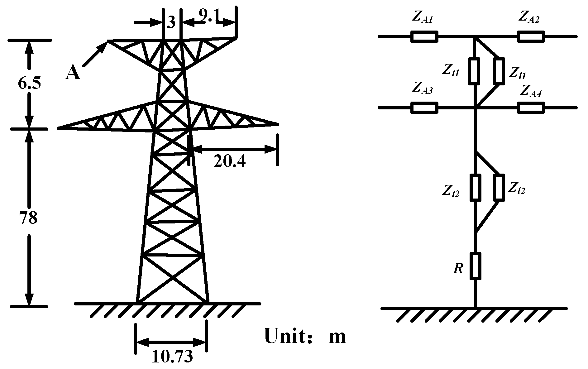
4.1. Simulation Model and Parameters

Figure 6 shows the actual shape of the ±1100 kV tower used for the calculation and its model diagram for this paper. The parameters are shown in Table 1. Among them, the surge impedance of the main body part Zt, the bracings Zl, and the cross arms ZA can be calculated by Equations (1)–(3), respectively. R is the tower grounding resistance, which is set to 10 Ω. The calculated surge impedance of the model is shown in Table 2.
The lightning current is simulated by the double-exponential model. The impedance of the lightning channel is 300 Ω and its amplitude is 260 kA. Besides, take the top of the tower as a lightning strike point for the analysis. The insulator is simulated with a 1 pF capacitor and the Leader Development Method is taken as its flashover criterion. The transmission line connecting the two sides of the tower adopts the PSCAD Frequency Dependent (phase) model. The distant towers and transmission lines adopts the Bergeron model [20]. Its surge impedance takes 300 Ω, and wave speed takes 3 × 10⁸ m/s, shown in Figure 7.

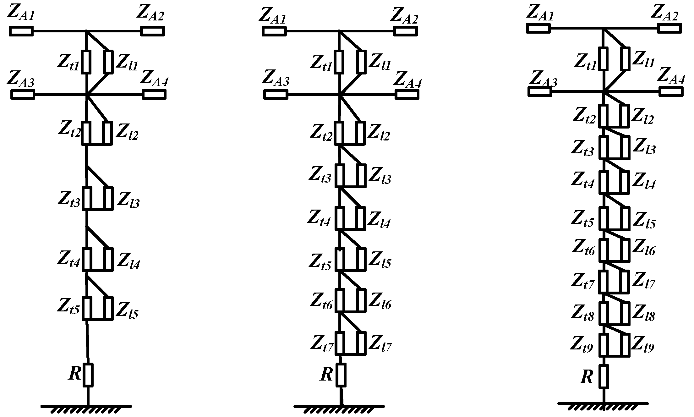
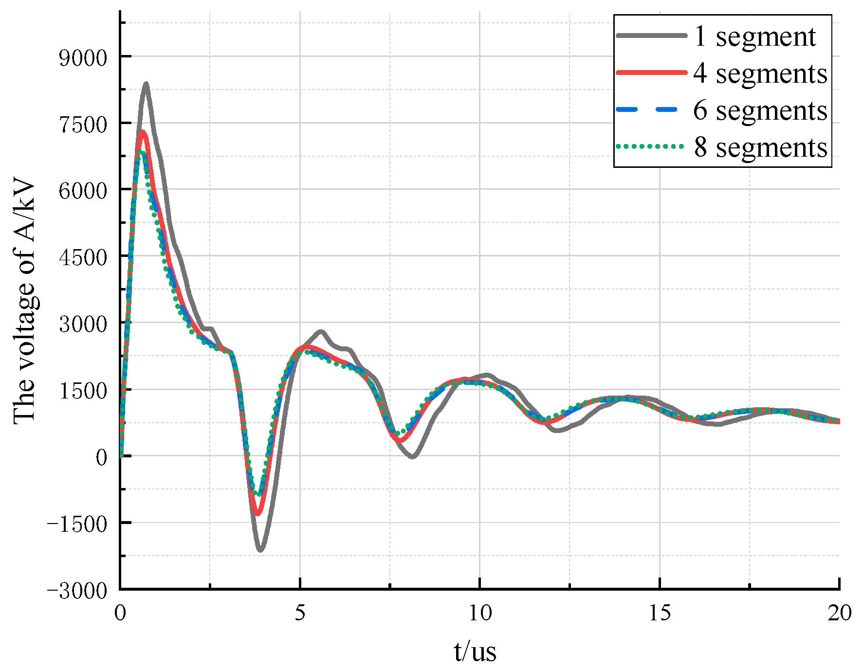
4.2. Simulation Results of the Multi-Segment Multi-Surge Impedance Model

For the UHV tower, the nominal height is larger, occupying more than 50% of the height of the tower. The structure and size of the tower body from the top to the bottom vary greatly. If only one surge impedance is used to model the nominal height, the influence of the spatial structure changes of the tower on its electromagnetic transient responses cannot be accurately reflected. Therefore, this paper divides the nominal height into 4, 6, and 8 segments, and analyzes the influence of the refined division on the electromagnetic transient characteristics of the tower. The improved tower model is shown in Figure 8. The surge impedance of each segment is calculated by Equations (1)–(3). The parameters calculated for each model are shown in Table 3, Table 4 and Table 5 respectively.
This paper uses PSCAD/EMTDC to calculate the parameters of the multi-surge impedance model when the nominal height is divided into 1, 4, 6, and 8 segments, and analyzes the transient characteristics of the tower when lightning strikes. The intersection point of the lightning protection line and the tower is taken as the lightning strike point. That is point A in Figure 6. The obtained voltage waveform at the top of the tower is shown in Figure 9, and the dynamic process near the peak is shown in Figure 10. From the fluctuation process of the voltage in Figure 9 and the peak value of the voltage Figure 10, we can conclude:
(1)
As the number of segments in the nominal height increases, the amplitude of the voltage gradually decreases. Compared with the one segment model, the overvoltage amplitude of the 8 segments model decreased by about 15.6%. This is because as the number of the divided segments increases, the geometric spatial structure of the nominal height is modeled by more surge impedances; and the impedance values of the respective parts are sequentially reduced, so that the peak value of the voltage is correspondingly reduced.
(2)
When the nominal height is segmented differently, the overall fluctuation trend of the voltage is almost the same.
(3)
As the number of segments of the nominal height increases, the peak of the voltage appears earlier and earlier. Compared with the one segment model, the time the peak appears is about 0.15 μs ahead of time when the nominal height is divided into 8 segments. This is because the more the number of segments of the nominal height is, the smaller the height and the larger the equivalent radius is. Therefore, the surge impedance of the portion closer to the ground is smaller. That is, when the lightning wave has not transmitted to the bottom of the tower, some of the reflected waves have returned to the top of the tower. This reflected wave slows down the rise of the peak voltage and decreases the peak value.
(4)
When the number of segments of the nominal height increases, the gradient of the voltage peak reduction is getting smaller and smaller. For example, when 6 segments or 8 segments are used to represent the nominal height of the tower, the peak value and fluctuation of the voltage waveform at the top of the tower are not much different. It indicates that as the number of segments for modelling the nominal height reaches a certain level, the peak value will change little and reach its saturation value. Then, further subdivision will have little effect on the electromagnetic transient response of the tower.
In summary, the more parts of the nominal height is divided into, the more accurately the spatial structure of the tower is modeled, and the closer the wave process on the tower is to the actual situation. However, with the height and structure of the tower varying, the number of the segments for the nominal height is different to reach the saturation value. Therefore, when practical applications require high accuracy, the multi-segment multi-surge impedance model needs to test the number of segments for the saturation value, which lacks flexibility and reliability.

4.3. Simulation Results of the Non-Uniform Transmission Line Model

In order to verify the accuracy and effectiveness of the non-uniform transmission line model, this paper compares the electromagnetic transient response of the tower with the non-uniform transmission line model and with the multi-segment multi-surge impedance model. The voltage waveforms at the top of the tower are shown in Figure 11, and the dynamic process near the peak is shown in Figure 12.
It can be seen from Figure 11 and Figure 12 that the voltage waveforms with the non-uniform transmission line model has almost the same fluctuation trend as the eight-segment multi-surge impedance model. However, the differences lie in:
(1)
The peak of the voltage with the non-uniform transmission line model is lower.
(2)
The voltage waveform with the non-uniform transmission line model fluctuates more, but the basic fluctuation trend is consistent.
In theory, as the number of segments in the vertical section of the tower increases, the electromagnetic transient response of the tower is modeled more accurately. The fact that the vertical section is segmented, and each section is modeled by one surge impedance can be understood that each section of the tower is modeled with uniform distributed parameters. Since the parameters of the non-uniform transmission line model vary with the height, compared with the multi-segment multi-surge impedance model, it is similar that the number of segments of the non-uniform transmission line model is close to infinity. Therefore, the wave process is more complex than the multi-segment multi-surge impedance model, and the peak value is reduced correspondingly, which is also closer to the reality.
In summary, the non-uniform transmission line model is more accurate than the multi-surge impedance model. The model reflects that the parameters’ changes with the decrease of the height and the increase of the equivalent radius of the UHV tower, so it is closer to the transient fluctuation process of the actual tower. In the lightning protection analysis, the accuracy with the non-uniform transmission line model is higher, and the simulation results are more reliable.

5. Conclusions

In this paper, the multi-surge impedance tower model is introduced, and the non-uniform transmission line tower model is established. Then the electromagnetic transient response of the tower with the multi-segment multi-surge impedance model and with the non-uniform transmission line model are presented and compared. From the results we can draw the following conclusions:
(1)
As the number of segments of the nominal height increases, the peak value of the voltage at the top of the tower is gradually reduced, and the peak time is gradually decreased. When the number of segments reaches a certain level, the transient response waveform of the tower will change little.
(2)
The transient response of the tower with the non-uniform transmission line model is very close to the saturated response of the multi-segment multi-surge impedance model. It indicates that the results with the non-uniform transmission line model in lightning protection analysis are more reliable. So the non-uniform transmission line model should be selected.
(3)
It can be seen that the non-uniform transmission line model built in this paper is consistent with the electromagnetic transient response of the multi-segment multi-surge impedance model. It shows that the proposed model can reflect the changes of the spatial structure of the tower more realistically, and is more suitable for the lightning transient analysis of ±1100kV UHV tower than the multi-surge impedance model.
(4)
The accuracy of the tower model determines the reliability of the lightning protection analysis. As the structure of the tower becomes more and more complicated, the ordinary multi-surge impedance model is no longer applicable, and a more accurate tower model must be built. The future modeling of the tower should focus on the physical characteristics. The model of the tower should be able to better reflect the electric and magnetic field generated by the lightning current and the tower’s own structure.

Author Contributions

X.G. proposed the kernel of the method; Y.F. derived the expressions and provided the data; J.Y. and Z.X. performed the simulations and wrote the paper.

Funding

This research was funded by State Grid Corporation of China (0711-16OTL09413001-007).

Conflicts of Interest

The authors declare no conflict of interest.

References

  1. Wang, C.J.; Zhu, L.Y.; Ji, S.C.; Zhang, Q. Present and development of lightning protection for HV transmission lines and substations. Insul. Surge Arresters 2010, 3, 35–46. [Google Scholar]
  2. IEEE Working Group on Estimating Lightning Performance of Transmission Lines. A Simplified Method for Estimating Lightning Performance of Transmission Line. IEEE Trans. Power Appar. Syst. 1985, PAS-104, 919–932. [Google Scholar]
  3. Li, P.G. A new viewpoint about lightning trip-out of UHV transmission lines. Power Syst. Technol. 2000, 24, 63–65. [Google Scholar]
  4. Xu, Z.H. Lighting Transient Study of Transmission Tower and Analysis of Invaded Wave to Substation; North China Electric Power University (Hebei): Beijing, China, 2006. [Google Scholar]
  5. Hara, T.; Yamamoto, O. Modeling of a transmission tower for lightning-surge analysis. IEE Proc. Gener. Transm. Distrib. 1996, 143, 283–289. [Google Scholar] [CrossRef]
  6. Wang, D.J.; Zhou, H.; Chen, J.M.; Lao, J.; Zhu, T.; Bao, J.; Zhang, L.; Wang, J. Design of Multi-Surge Impedance Model for Ultra-High Transmission Tower and Analysis on Its Transient Characteristic Caused by Lightning Stroke. Power Syst. Technol. 2007, 31, 11–16. [Google Scholar]
  7. Du, L.; Mi, X.; Xiao, N.Z.; Yu, S.; Yang, Y.; Yang, Q. Equivalent Model of Cross Arm and Inclined Holder of Transmission Tower. High Volt. Eng. 2012, 38, 3025–3032. [Google Scholar]
  8. Gutierrez R, J.A.; Moreno, P.; Naredo, J.L.; Bermudez, J.L.; Paolone, M.; Nucci, C.A.; Rachidi, F. Nonuniform transmission tower model for lightning transient studies. IEEE Trans. Power Deliv. 2004, 19, 490–496. [Google Scholar] [CrossRef]
  9. Huangfu, Y.; Wang, S.; Wang, G.; Xu, W.; Zhang, H. Modeling and Insulation Performance Analysis of Composite Transmission Line Tower under Lightning Overvoltage. IEEE Trans. Magn. 2015, 51, 1–4. [Google Scholar] [CrossRef]
  10. Mo, F.J.; Chen, Y.P.; Ruan, J.J. Study on transmission tower models and their lightning performance calculation. Power Syst. Technol. 2004, 28, 80–84. [Google Scholar]
  11. Liang, Y.M.; Ge, D. Tower model in calculation of lightning protection on multi-circuit transmission line with same tower. High Volt. Eng. 2006, 31, 76–77. [Google Scholar]
  12. Zhang, Y.; Gao, Y.D.; Du, B.; Shi, W. New tower model in calculation of lightning protection on transmission line. J. Xi’an Jiaotong Univ. 2004, 38, 365–368. [Google Scholar]
  13. Yang, Q.; Zhao, J.; Sima, W.X.; Feng, J.; Yuan, T. Lightning back-flashover performance of the Yun-Guang UHV DC transmission lines. High Vol. Eng. 2008, 34, 1330–1335. [Google Scholar]
  14. Zhang, Y.J.; Sima, W.X.; Zhang, Z.J. Summary of the study of tower models for lightning protection analysis. High Vol. Eng. 2006, 32, 93–97. [Google Scholar]
  15. Ishii, M.; Baba, Y. Numerical electromagnetic field analysis of tower surge response. IEEE Trans. Power Deliv. 1997, 12, 483–488. [Google Scholar] [CrossRef]
  16. Naredo, J.L.; Moreno, P.; Soudack, A.C.; Marti, J.R. Frequency Independent Representation of Transmission Lines for Transient Analysis through the Method of Characteristics. In Proceedings of the Joint International Power Conference Athens Power Tech, Athens, Greece, 5–8 September 1993. [Google Scholar]
  17. Ishii, M.; Kawamura, T.; Kouno, T.; Ohsaki, E.; Shiokawa, K.; Murotani, K.; Higuchi, T. Multistory transmission tower model for lightning surge analysis. IEEE Trans. Power Deliv. 1991, 6, 1327–1335. [Google Scholar] [CrossRef]
  18. Jordan, E.C.; Andrews, C.L. Electromagnetic Waves and Radiating Systems. Am. J. Phys. 1968, 19, 477–478. [Google Scholar] [CrossRef]
  19. Du, L.; Mi, X.; Yang, Y.; Yang, Q. The equivalent model of transmission tower under lightning striking. High Volt. Eng. 2011, 37, 28–33. [Google Scholar]
  20. Imece, A.F.; Durbak, D.W.; Elahi, H.; Kolluri, S.; Lux, A.; Mader, D.; McDermott, T.E.; Morched, A.; Mousa, A.M.; Natarajan, R.; et al. Modeling guidelines for fast front transients. IEEE Trans. Power Deliv. 2002, 11, 493–506. [Google Scholar]
Figure 1. The diagram of multi-surge impedance model.
Energies 12 00445 g001
Figure 2. Schematic diagram of the equivalent radius.
Energies 12 00445 g002
Figure 3. Tower on the DC pole and the equivalent model of the tower.
Energies 12 00445 g003
Figure 4. Conical antenna model of vertical conductor infinitesimal element. (a) The infinitesimal element of the vertical conductor; (b) The Conical antenna model.
Energies 12 00445 g004
Figure 5. Equivalent radius of the vertical infinitesimal element of the tower.
Energies 12 00445 g005
Figure 6. Parameters and the multi-surge impedance model of the tower.
Energies 12 00445 g006
Figure 7. Simulation model for this paper.
Energies 12 00445 g007
Figure 8. Tower model when the nominal height is divided into 4, 6, and 8 segments.
Energies 12 00445 g008
Figure 9. Simulation results of the voltage for multi-segment multi-surge impedance model.
Energies 12 00445 g009
Figure 10. The peak value of the voltage for multi-segment multi-surge impedance model.
Energies 12 00445 g010
Figure 11. Simulation results of the voltage with the non-uniform transmission line model and with the multi-segment multi-surge model.
Energies 12 00445 g011
Figure 12. The peak value of the voltage with the non-uniform transmission line model and with the multi-segment multi-surge model.
Energies 12 00445 g012
Table 1. Parameters of the tower.
Tower ParametersParameters of the Main Body
Tower materialIronNumber of columns4
Tower resistivity9.09 × 10−7 Ω/mColumn equivalent radius0.1 m
Tower magnetic permeability4π × 10−4 H/mMaximum distance between columns10.73 m
Ground resistivity30 Ω·mMinimum distance between columns3.0 m
Table 2. Parameters for the multi-surge impedance model.
Parameter NameSurge Impedance/ΩParameter NameSurge Impedance/Ω
ZA1288ZA2288
ZA3270ZA4270
Zt1180Zl11620
Zt2141Zl21269
Table 3. Parameters for four segments of the nominal height.
Parameter NameSurge Impedance/ΩParameter NameSurge Impedance/Ω
ZA1288ZA2288
ZA3270ZA4270
Zt1180Zl11620
Zt2160Zl21440
Zt3130Zl31170
Zt496Zl4864
Zt546Zl5414
Table 4. Parameters for six segments of the nominal height.
Parameter NameSurge Impedance/ΩParameter NameSurge Impedance/Ω
ZA1288ZA2288
ZA3270ZA4270
Zt1180Zl11620
Zt2163Zl21467
Zt3143Zl31287
Zt4121Zl41089
Zt597Zl5873
Zt667Zl6603
Zt720Zl7180
Table 5. Parameters for eight segments of the nominal height.
Parameter NameSurge Impedance/ΩParameter NameSurge Impedance/Ω
ZA1288ZA2288
ZA3270ZA4270
Zt1180Zl11620
Zt2165Zl21485
Zt3149Zl31341
Zt4134Zl41206
Zt5117Zl51053
Zt698Zl6882
Zt777Zl7693
Zt848Zl8432
Zt93Zl927

