Article

Hybrid Energy Management System for Operation of Wind Farm System Considering Grid-Code Constraints

1
Department of Electrical Engineering, Incheon National University, 12-1 Songdo-dong, Yeonsu-gu, Incheon 406-840, Korea
2
Research Institute for Northeast Asian Super Grid, Incheon National University, 119 Academy-ro, Yeonsu-gu, Incheon 22012, Korea
*
Author to whom correspondence should be addressed.
Energies 2019, 12(24), 4672; https://doi.org/10.3390/en12244672
Submission received: 29 October 2019 / Revised: 25 November 2019 / Accepted: 5 December 2019 / Published: 9 December 2019
(This article belongs to the Special Issue Wind Turbine 2020)

Abstract

:
In this paper, a hybrid energy management system is developed to optimize the operation of a wind farm (WF) by combining centralized and decentralized approaches. A two-stage optimization strategy, including distributed information sharing (stage 1); and centralized optimization (stage 2) is proposed to find out the optimal set-points of wind turbine generators (WTGs) considering grid-code constraints. In stage 1, cluster energy management systems (CEMSs) and transmission system operator (TSO) interact with their neighboring agents to share information using diffusion strategy and then determine the mismatch power amount between the current output power of WF and the required power from TSO. This amount of mismatch power is optimally allocated to all clusters through the CEMSs. In stage 2, a mixed-integer linear programming (MILP)-based optimization model is developed for each CEMS to find out the optimal set-points of WTGs in the corresponding cluster. The CEMSs are responsible for ensuring the operation of WF in accordance with the requirements of TSO (i.e., grid-code constraints) and also minimizing the power deviation for the set-points of WTGs in each cluster. The minimization of power deviation helps to reduce the internal power fluctuations inside each cluster. Finally, to evaluate the effectiveness of the proposed method, several case studies are analyzed in the simulations section for operation of a WF with 20 WTGs in four different clusters.

1. Introduction

In recent years, the demand for renewable energy sources (RESs) is increasing dramatically due to the exhaustion of fossil fuels as well as the shortage of electricity supplies. The production of electric power from RESs such as hydro, geothermal, solar, wind, and biomass are getting more attention [1,2]. Among all the RESs, wind energy is becoming a trend and competing with conventional energy sources [3]. According to calculations by The Global Wind Energy Council, the total global energy generated by wind turbine generators (WTGs) could be up to 19% by 2030 and 25–30% by 2050 [4].
The increase in wind energy utilization in the power system requires a large number of WTGs and these WTGs are installed in a large area to maximize wind energy usage. Therefore, the independent operation of individual WTGs causes many difficulties for transmission system operators (TSOs). As a result, all WTGs located at the same geographic area are grouped into a wind farm (WF) system [5]. In a WF, the operation of WTGs is coordinated to achieve common operational objectives of the whole system, such as maximizing the output power, minimizing the operation costs, and so on.
Nowadays, the rapid expansion of WF systems allows them to generate a large output of power and inject it into the power system. Therefore, the operation of such systems without any technical requirement may cause adverse effects to the power system stability, especially small or islanded power systems. To mitigate the adverse effects of large WFs on the power systems, the operation of such WF systems needs to comply with various constraints from TSOs, i.e., grid-code constraints [6,7,8]. These constraints require the WF system to be capable of being similar to the conventional power plants, such as active/reactive power control [9,10], frequency control [11], voltage control [12], fault-ride-through capability [13,14], and so on.
To ensure the operation of WF following above requirements from TSO, energy management systems (EMSs) is required, which is responsible for optimally determining the set-points of all WTGs in WF. The development of an EMS is typically divided into centralized approach or decentralized approach. In centralized approach, a central EMS requires all information from the WTGs and carries out optimization for determining set-points for WTGs. The optimal solutions are then sent back to individual WTGs. The authors in [15] have investigated a centralized EMS to operate a WF system, which includes a central controller and WTGs’ controller. The central controller gathers information from all local WTGs’ controllers and determines the power generation of the WF system by sending out set-point to each individual WTG. The authors in [16] have presented a new methodology for the scheduling of WTGs that provide frequency response. The proposed scheduling has been implemented with a centralized approach that requires a two-way communication channel between the WTGs and a central entity. However, WTGs in a large WFs are often scattered in a large area. Developing a centralized energy management system on a large area (e.g., a WF system) could be costly and complex, especially for the communication network.
Therefore, several studies have also developed distributed energy management systems for operation of WF. The authors in [17] have proposed a decentralized-based algorithm to design a robust static synchronous compensator control for increasing dynamic transfer capability in WF systems. The authors in [18] have investigated a decentralized model-free approach for optimizing power generation of WFs with limited information-sharing among WTGs. The authors in [19] have addressed the problem of WF control for load mitigation using a distributed feedforward control scheme. However, developing a fully distributed system for a WF with a huge number of WTGs also faces many difficulties in operating the system. For example, it could take a long time for convergence to find out optimal set-points of WTGs.
It can be observed from the literature survey that most of the existing studies have mainly focused on developing EMSs for WFs based on either centralized approaches [15,16] or decentralized approaches [17,18,19]. In a large WF system, both centralized and decentralized EMSs could face many difficulties and challenges. For instance, in a centralized EMS, a two-way communication channel between the WTGs and the central entity is required [15,16]. With a huge number of WTGs allocated in a large area of the WF system, the development of a centralized management system is often expensive and the computational burden for the central entity also significantly increases. Furthermore, there are many events that could occur in a large WF. This also causes difficulties in the operation of WF, especially any failure in the central entity can cause the wrong operation of the entire system or even leads to the disconnection of the WF system from the power system. On the other hand, in decentralized EMS, a WTG only interacts with its neighboring WTGs. This can reduce the computational burden and investment costs [17,18,19]. However, developing a fully distributed system for a huge number of WTGs requires a long time for convergence to determine the optimal set-points of WTGs. It could not be suitable for the operation of a WF system, where input data (wind speed, wind direction, etc.) often change and require rescheduling.
In order to overcome the disadvantages of both approaches, a hybrid EMS is developed in this study to optimize operation of WF by combining both decentralized and centralized approaches. In this proposed hybrid EMS, instead of a large centralized EMS for the entire WF system, we developed a cluster energy management system (CEMS) for each group of adjacent WTGs. This significantly reduces the size of CEMSs compared with a centralized EMS for the entire WF system and also makes the operation and maintenance of CEMS simpler and easier. In addition, instead of sharing information among all WTGs in a fully distributed way, the hybrid EMS only shares information between CMESs and TSO. This significantly reduces the number of agents as well as the convergence time for information sharing process.
In order to optimize the operation of WF, we developed a two-stage optimization strategy to find out optimal set-points of WTGs and also fulfill the grid-code constraints from TSO. The proposed method is divided into two stages, so-called distributed information sharing (stage 1) and centralized optimization (stage 2). In stage 1, CEMSs and TSO interact with their neighboring agents to share information in the system using diffusion strategy in a distributed manner to reduce convergence time [20]. After the information-sharing process, the amount of mismatch power can be easily calculated based on the current WF’s output power and the required power from TSO. This amount of mismatch power is optimally allocated to all clusters through the CEMSs. In stage 2, an MILP-based optimization model is developed for each CEMS and the CEMS will perform optimization to find out optimal set-points of WTGs for balancing the mismatch power in the corresponding cluster (taken from stage 1). The objective of CEMSs is to ensure the operation of WF in accordance with the requirements from TSO and also minimizes the power deviation for the set-points of WTGs inside each cluster. The minimization of power deviation helps to reduce the unnecessary power fluctuation inside clusters. Finally, to evaluate the effectiveness of the proposed strategy, several case studies are performed in the numerical simulations section for operation of a WF with 20 WTGs divided into four different clusters.
The major findings of this study are presented as follows:
  • A hybrid energy management system is developed to optimize the operation of a large WF system by combining both centralized and decentralized approaches. This makes the design of communication network much simpler. Instead of developing a large EMS for the entire WF system, each cluster is managed by a local EMS, i.e., cluster EMS. The mismatch power in the WF system is also simply updated through an information-sharing process between CEMSs and TSO in a distributed manner.
  • A two-stage optimization is also proposed to optimize the operation of the WF system to reduce the power deviation for set-points of WTGs. Moreover, CEMSs and TSOs share information to optimally determine the amount of increase/decrease for each cluster using diffusion strategy. The use of diffusion strategy helps to reduce the time for sharing information in a distributed way.
  • Different grid-code constraints are given by TSOs for the operation of WF. These constraints require the WF system to control its output power in each specific operation situation. The proposed method is also developed considering several important grid-code constraints. The simulation results prove that the WF system can adjust its output with any requirement from TSO.

2. System Model

2.1. Configuration of Wind Farm System

In this section, the configuration of a WF system is presented in detail, including two main parts, i.e., electric power network and communication network. Figure 1a shows the electric power network of WF system, which is comprised of 20 WTGs. In this paper, we assume that WTGs in WF are divided into four clusters and each cluster is a group of five WTGs. The WF is connected to the power system through a HVDC transmission line. Connecting WF to the power system requires the ability to control output power of WF to satisfy different grid-code constraints from TSO. During the operation time of WF, the grid-code constraints from TSO, e.g. the amount of required power, the amount of reserved power are announced to WF and the optimal set-points for WTGs will be determined to fulfill those operation constraints.
To serve the sharing information process, a communication network is required for developing the hybrid energy management system. The detailed communication network is shown in Figure 1b. Each cluster is a group of closed WTGs and is operated by a centralized EMS, i.e., CEMS to optimize the set-points of WTGs in the corresponding cluster. The information-sharing process between CEMSs and TSO is done using distributed methods—e.g., consensus algorithm, diffusion strategy.

2.2. Grid-Code Constraints

Increasing the level of wind power penetration into power systems could adversely affect the system stability, especially the connection of large WFs. This leads to the necessity of determining specific technical requirements (i.e., grid-code constraints) for connecting large WFs to the power system and these constraints are often issued by TSOs. This paper only studies the scheduling of WF in normal operation mode. Therefore, we only consider some related requirements, i.e., requirements on the WF’s output power and WF’s reserve capacity [6,7,8].
The constraint on the output power limit for WF is shown in Figure 2a. The possible output power of WF is sum of the maximum output power of all WTGs (i.e., maximum power point tracking (MPPT)). It can be seen that output power of WF is always lesser than or equal to a limited power provided by TSO. The WF system generates maximum output power if the possible power is lower than the limited power. This means the operation of all WTGs are set at MPPT. Conversely, when the possible power is greater than the limited power, the WF output is bounded by the limited power. Therefore, the WF’s output power is set to limited power point. WTGs are optimally adjusted to fulfill that required power. Figure 2b shows the operation of WF in reserve power mode. In this mode, TSO requires a certain amount of reserve power in WF, therefore, the WTGs’ output power is reduced to meet this required reserve capacity. Compliance with grid-code constraints from the TSO can help WF systems avoid power imbalance. CEMSs always adjust the set-points of WTGs to satisfy the total power demand from TSO.

3. Proposed Operation Strategy

As shown in Section 2.1, the adjacent WTGs are connected to form a cluster and are operated by a CEMS. The CEMSs and TSO share their information in the system using a distributed method. The proposed method is divided into two stages, as follows.
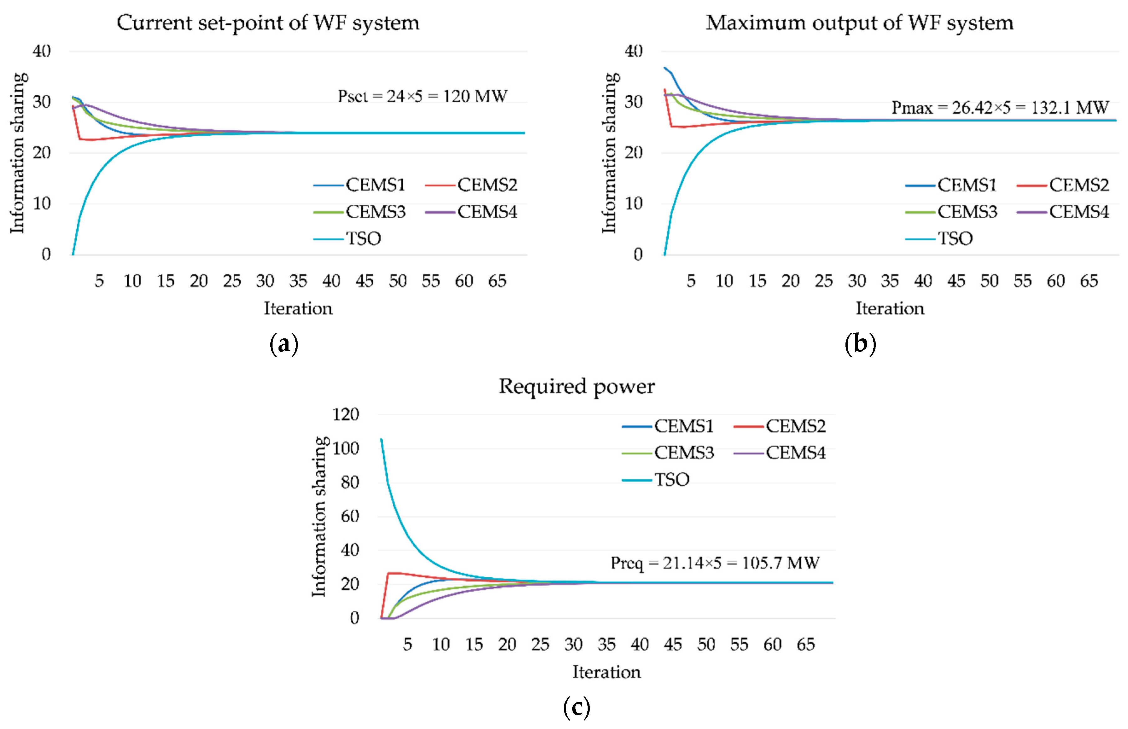
  • Stage 1—Information sharing: In this stage, the CEMSs and TSO will share information to determine the mismatch power between required power from TSO and current output power of WF. This amount of mismatch power is compensated by adjusting the output power of clusters.
  • Stage 2—Cluster optimization: In this stage, each CEMS will optimize the set-points of WTGs for fulfilling the power mismatch amount receiving from stage 1 and minimize the power deviation for the set-points of WTGs inside the cluster.
Each cluster is managed by a CEMS and therefore, any changes in the configuration of each cluster will be updated by CEMS (e.g. connection/disconnection of WTGs). The current output power, the maximum output power of each cluster, and the required power from TSO is also updated and shared among CEMS and TSO. The information-sharing process between CEMSs and TSO is carried out by using diffusion strategy in a distributed manner. This operation approach supports the plug-and-play function in the system. For example, a new cluster is connected in the WF system, the agents will update their neighboring clusters and start the information-sharing process without any action from WF operators [21,22].
Therefore, the proposed method can be applied for the optimal operation of any WF system or any change in the configuration of WF system. Performing again the information-sharing process helps agents update the changes in the system configuration and therefore find out new optimal set-points of WTGs. The whole process for optimal operation of WF system is shown in detail in Figure 3.

3.1. Stage 1: Distributed Approach for Sharing Information among Clusters and TSO

Stage 1 for distributed information sharing is presented in detailed, as shown in Figure 4a. Information on the required power from TSO, current output power in each cluster, and the maximum output power from clusters at a given interval is shared between CEMSs and TSO. The mismatch power amount between current output of WF and the required power of TSO is determined after the information sharing process. The amount of this mismatch power is allocated to all clusters through CEMSs.
Various methods have been introduced to share information among agents in a distributed way—e.g., consensus algorithm [23], diffusion strategy [24,25], etc. However, the convergence rate of consensus algorithm is slower than diffusion strategy [20,24]. Therefore, in this study, we also use diffusion strategy for sharing information in the WF system. In diffusion strategy, an agent only needs to interact with its neighboring agents via a communication network. The connection among agents in the communication network is represented by an adjacent matrix A determined by using Metropolis rule [20,25], as expressed in (1).
a i j = { 1 max ( n i , n j ) i N j \ { j } 1 i N j \ { j } a i j i = j 0 otherwise
where a i j is element in row i, column j of matrix A; n i , n j is the number of connected agents to agents i and j, respectively; a i j = 0 if there is no connection between agents i and j.
Algorithm 1 shows the interaction process among agents in a distributed manner. Firstly, input parameters (μi) are initialized and the adjacent matrix A is determined using Equation (1). This information is taken as input data for the information sharing process. In each iteration, the new state of agent i is updated via its previous state, neighboring agents’ previous state, and local stochastic gradient. This strategy is used to share information in step 1 and step 2. After the information sharing process, the amount of mismatch power can be easily determined based on the information of the required power and current output power. This amount of mismatch power is allocated to all clusters, as shown in step 3. After determining the amount of mismatch power for each cluster, the process will move to stage 2 for optimizing the set-points of WTGs.
Algorithm 1 Diffusion strategy for sharing information
1:Input parameters, i.e., μ i
2:Determine adjacent matrix A using Equation (1)
3:while error < available value do
4: for all i < N do
5: ϕ k 1 , i = j N i a i , j x k 1 , j
6: x k , i = ϕ k 1 , i μ i s ^ i , k ( ϕ k 1 , i )
7: End
8: end while

3.2. Stage 2: Centralized Approach for Optimal Operation in Clusters

In stage 1, the amount of power mismatch for each cluster has been determined. Therefore, the main concern in stage 2 is to optimize the set-points of WTGs for fulfilling the amount of mismatch power in WF. The optimization flowchart using the centralized approach is described in detail in Figure 4b. Each CEMS receives the detailed information of WTGs inside the corresponding cluster—i.e., maximum output power from WTGs, power ramp-rate constraints, and so on. Each WTG can adjust its output power within [Pmin,Pmax] with ramp-up and ramp-down constraints. Each CEMS is responsible for determining the optimal set-points of WTGs to fulfill the power requirements and minimizing the power deviation for the set-points of WTGs. After determining set-points of WTGs inside clusters, each CEMS sends back the reference signals to all WTGs for implementation. This process is repeated whenever there is any change in input data from WTGs side or from stage 1.

4. Mathematical Model

This section presents a detailed mathematical model for both two stages of the proposed method. A diffusion strategy-based information-sharing is presented for stage 1 and an MILP-based optimization model is presented for stage 2.

4.1. Diffusion Strategy-Based Information-Sharing

Based on the configuration of the communication network, an adjacent matrix A is determined using Metropolis rule, as given by Equation (1). In this paper, the matrix A for the test system is expressed in (2).
A = ( 3 / 4 1 / 4 0 0 0 1 / 4 1 / 4 1 / 4 0 1 / 4 0 1 / 4 1 / 2 1 / 4 0 0 0 1 / 4 3 / 4 0 0 1 / 4 0 0 3 / 4 )
D i f f u s i o n   s t r a t e g y : { ϕ k 1 , i = j N i a i , j x k 1 , j x k , i = ϕ k 1 , i μ i s ^ i , k ( ϕ k 1 , i )
where xi,k is state of agent i at iteration k; φi,k−1 is intermediate state for agent i at previous iteration k − 1; μi is a non-negative updating parameter of agent i; s ^ i , k ( ϕ k 1 , i ) is stochastic gradient of intermediate state φ for agent i at iteration k.
By using matrix A, an agent i can easily update its state at each iteration, as shown in (3). New state (xk,i) is updated via the previous state (xk−1,j) and the stochastic gradient (φi,k). The stochastic gradient can be simply calculated by the difference of intermediate state (φ) at two consecutive iterations, as given in (4). This process is used for information sharing in this study.
s ^ i , k ( ϕ k 1 , i ) ϕ k 1 , i ϕ k 2 , i

4.2. MILP-Based Optimization

An MILP-based mathematical model is presented in detailed in this section for stage 2. The main purpose of this stage is to optimize set-points of WTGs to meet required power from stage 1. Furthermore, the optimization model also minimizes the power deviation for the set-points of WTGs inside each cluster and makes the output power of WTGs smoother. The objective function for the optimization model is presented in Equation (5).
M i n { p Δ , t , i . Δ P t , i + n = 1 N i p n , i . | P n , t , i P n , t 1 , i | + m , n = 1 m n N i p m n , t , i . | P m , t , i P n , t , i | } t T , i I
It can be seen that the absolute values in the objective function (5) causes this model to be non-linear. In order to solve the optimization problem using a MILP solver (e.g., CPLEX, GAMS, etc.), it is necessary to convert the objective function (5) into a linear function. The linearization process is carried out using additional variables, as expressed in (6) [26].
M i n { p Δ , t , i . Δ P t , i + n = 1 N i p n , i . D P n , t , i + m , n = 1 m n N i p m n , t , i . D P m n , t , i } t T , i I
P D n , t , i P n , t , i P n , t 1 , i n N i , t T , i I
P D n , t , i ( P n , t , i P n , t 1 , i ) n N i , t T , i I
P D m n , t , i P m , t , i P n , t , i m , n N i , t T , i I
P D m n , t , i ( P m , t , i P n , t , i ) m , n N i , t T , i I
The use of these additional variables in (6) lead to four more constraints, as shown in (7)–(10). The detailed constraints related to the operation of the WF system are presented in (11)–(17).
s n , t , i = { 1   if   WTGn   is   in   service 0   otherwise n N i , t T , i I
s n , t , i . P n , i min P n , t , i s n , t , i . min { P n , i r a t e , P n , t , i a v a i l } n N i , t T , i I
P n , t , i a v a i l = 1 2 C p _ o p t ( β n , i , λ n , i ) ρ π R 2 v n , t , i 3 n N i , t T , i I
n = 1 N i ( Δ P n , t , i . s n , t , i ) = Δ P t , i t T , i I
The operation state of each WTG is determined by (11). This state shows whether the WTGs are ready for generating power. The operation bounds of each WTG is shown in (12) considering its operation state. The available power of WTGs at a given interval is calculated by (13) based on the WTGs’ parameters and wind characteristics [27]. Equation (14) shows the relation between changing the set-points of WTGs and mismatch power in a cluster. This constraint ensures that each CEMS always tries to adjust the set-points of WTGs for balancing the mismatch power in the corresponding cluster. To avoid the power imbalance in the WF system, there is always an interaction between the WF and TSO about the amount of generated power, the maximum amount of generated power from the WF system, and the amount of required power from TSO. By doing so, TSO will require a suitable amount of output power for the WF system in each operation situation.
Constraints (15)–(17) presents the bounds for controlling the output power of WTGs in two consecutive intervals. Constraint (15) ensures that WTGs can only adjust their output power with maximum ramp-up/ramp-down rates. Constraint (16) shows that the power generation from a WTG is always lower than its available power at t + 1.
P n , t , i P n , i R D P n , t + 1 , i P n , t , i + P n , i R U n N , t T , i I
P n , i min P n , t + 1 , i P n , t + 1 , i a v a i l n N , t T , i I
Finally, the operation bounds of WTGs for two consecutive time intervals are summarized in (17) by combining both constraints (15) and (16), and the minimum/maximum generation point of WTG.
max { P n , i , t P n , i R D , P n , i min } P n , t + 1 , i min { P n , t , i + P n , i R U , P n , i r a t e , P n , t + 1 , i a v a i l } n N , t T , i I

5. Numerical Results

5.1. Hierarchical Control Structure of WF

The control structure for WF systems are usually developed based on hierarchical control structure, including three levels with different time frames [15,28,29] as follows:
  • Primary control level is the fastest level to ensure the reference tracking of frequency and voltage for each WTGs.
  • Secondary control level helps improve power quality and transient stability in WF system.
  • Tertiary control level is designed to determine the optimal set-point for each WTG to achieve a common operation objective of the WF system.
In this study, we only focused on tertiary control level for the WF system. This control level aims to determine the optimal set-points for WTGs to achieve a long-term operation objective of the WF system. Moreover, in order to ensure stability for the operation of WF, the power balance is always maintained in WF between the total output power from WTGs and the required power from the power system.

5.2. Input Data and Case Study

Section 2.1 has presented the test WF system used to evaluate the proposed method. The WF system is comprised of 20 WTGs and adjacent WTGs are grouped into a cluster. This helps to reduce the complexity in designing energy management systems. In this study, WTGs are divided into four different clusters, as shown in Figure 5 and each cluster is operated by a centralized energy management system, i.e., cluster EMS. All WTGs are the same type and detailed parameters are listed as follows [30].
  • Rated power: 10 MW
  • Minimum operation point: 1 MW
  • Maximum ramp-up/ramp-down: 2 MW during 30 seconds
The output power of WTGs with the voltage of 33 KV is transmitted to a collection bus. At this collection bus, the voltage is increased to 154 kV using a step-up transformer for an HVDC transmission line with the DC line voltage of 300 kV. The output power of the whole WF system is then injected into the power system at the voltage of 154 kV.
CEMSs are responsible for finding out optimal set-points of WTGs within [Pmin,Pmax] to balance the amount of power mismatch for the corresponding cluster. The two-stage model for information sharing and optimization is implemented in Visual Studio C++ with integration of CPLEX 12.6 [31].
All case studies are presented in Figure 6, as follows.
  • At t1, WF is initially operated in limited power mode with limited power at 100 MW.
  • At t2, the limited power increases from 100 MW to 120 MW. The power mismatch in the WF system is 20 MW and therefore the WTGs will be controlled to increase their set-points to balance this amount of mismatch power.
  • At t3, WF is switched to the reserve mode. A certain amount of reserve power is required in WF system. Therefore, the set-point of WTGs should be again determined to fulfill the requirement for reserve capacity. In this case study, the reserve capacity is required to be 20%.
Input data for the maximum output power of WTGs is tabulated in Table 1 at t1, t2, and t3. At a given time, the output power of WTGs is adjustable within [Pmin,Pmax], where Pmin is 10% of rated power (1 MW) and Pmax are taken in Table 1. In the next section, information sharing process, optimal set-points of WTGs, WF’s output power, and reserve capacity in each cluster and WF will be presented in detail.

5.3. Simulation Results

5.3.1. Case 1: The WF System Initially Operates During t1t2 with Limited Power at 100 MW

At t1, WF is operated in limited power mode and the limited power is 100 MW, as shown in Figure 6. The maximum generated power of clusters 1, 2, 3, and 4 are 28.7 MW, 24 MW, 29.7 MW, and 23.5 MW, respectively, as shown in Table 1. In WF system, CEMSs and TSO share information in a distributed manner using diffusion strategy. In this case, each cluster should generate 25 MW. However, the maximum generated power for clusters 2 and 4 are only 24 MW and 23.5 MW, respectively. After information-sharing process among CEMSs and TSOs, clusters 2 and 4 are set to maximum output power and the required power for clusters 1 and 3 are 26.25 MW to maintain the power balance between the generated power from WF and the required power from TSO. It can be seen that the set-points of all WTGs in clusters 2 and 4 are set to maximum output power, as shown in Figure 7. Since the required power for both clusters 1 and 3 are 26.25 MW. CEMSs perform optimization to determine the set-points of WTGs in these clusters to fulfill the required power and reduce power deviation for the set-points of WTGs. The optimal set-point of WTGs in clusters 1 and 3 is also shown in Figure 7. The proposed operation strategy helps minimize the change in the set-points of WTGs with any input data.
Due to the constraint for the maximum output power of WF system (e.g., limited power mode), some clusters could not generate maximum output power (i.e., cluster 1 and cluster 3). This amount of unused wind energy can play a role as a reserve capacity in WF. This reserve power can be used in emergency situations, for example, the outage of WTGs or changing in the operation mode of WF. The reserve capacity for each WTGs is shown in Figure 8. It can be seen that the amount of reserve power in clusters 2 and 4 is zero because all WTGs have set to the maximum output power. The reserve capacity of WF is the total power reserve from all clusters. In this case study, the reserve capacity in WF is 5.9 MW (around 5.6%).

5.3.2. Case 2: The Limited Power Increases to 120 MW at t2

At t2, the WF system still operates in the limited power mode and the limited power is changed from 100 MW to 120 MW. At this time, the maximum output power of clusters 1, 2, 3, and 4 are 31 MW, 31.8 MW, 30.8 MW, and 33.8 MW, respectively, as shown in Table 1. The current output power of the clusters 1, 2, 3, and 4 are 26.25 MW, 24 MW, 26.25 MW, and 23.5 MW, respectively. The change in limited power information from TSO is updated through the information-sharing process using diffusion strategy. Information for the current output power, the maximum output power of WF, and the required power from TSO are determined after a number of iterations, as shown in Figure 9a–c, respectively. Based on this information, the mismatch power between the required power and the current output power is easily determined, Pmismatch = Preq − Pset = 120 − 100 = 20 MW. This amount of mismatch power is allocated to four clusters. Based on the current output power and the maximum output power, it is easy to calculate the amount of increasable power (i.e., Pmax,i − Pset,i) from clusters 1, 2, 3, and 4 are 4.8 MW, 7.8 MW, 4.6 MW, 10.3 MW, respectively. In order to maintain the power balance and minimize the change in the set-points of clusters, the amount of increasing power from clusters 1, 2, 3, and 4 are determined to 4.8 MW, 5.3 MW, 4.6 MW, and 5.3 MW, respectively. It can be seen that clusters 1 and 3 will increase their output power to maximum value because the average increasing power of each cluster is 5 MW. The remaining amount of power mismatch is divided for two other clusters 2 and 4, hence each cluster will increase its output power by 5.3 MW.
After determining the amount of increasing power from each cluster, CEMSs carry out optimization to adjust the set-points of WTGs to fulfill the required power and also minimize the power deviation for the set-points of WTGs inside each cluster. It can be seen from Figure 10 that all WTGs in clusters 1 and 3 are set at the maximum output power. The set-points of WTGs in clusters 2 and 4 are determined to minimize the power deviation in each cluster. The reserve capacity of WF can be calculated by the total reserve capacity of all WTGs. In clusters 1 and 3, all WTGs are set to maximum output power, therefore there is no reserve capacity. The reserve capacity in each WTG in each cluster is shown in detail in Figure 11. In this case study, the reserve capacity in the WF system is 7.5 MW (around 5.9%).

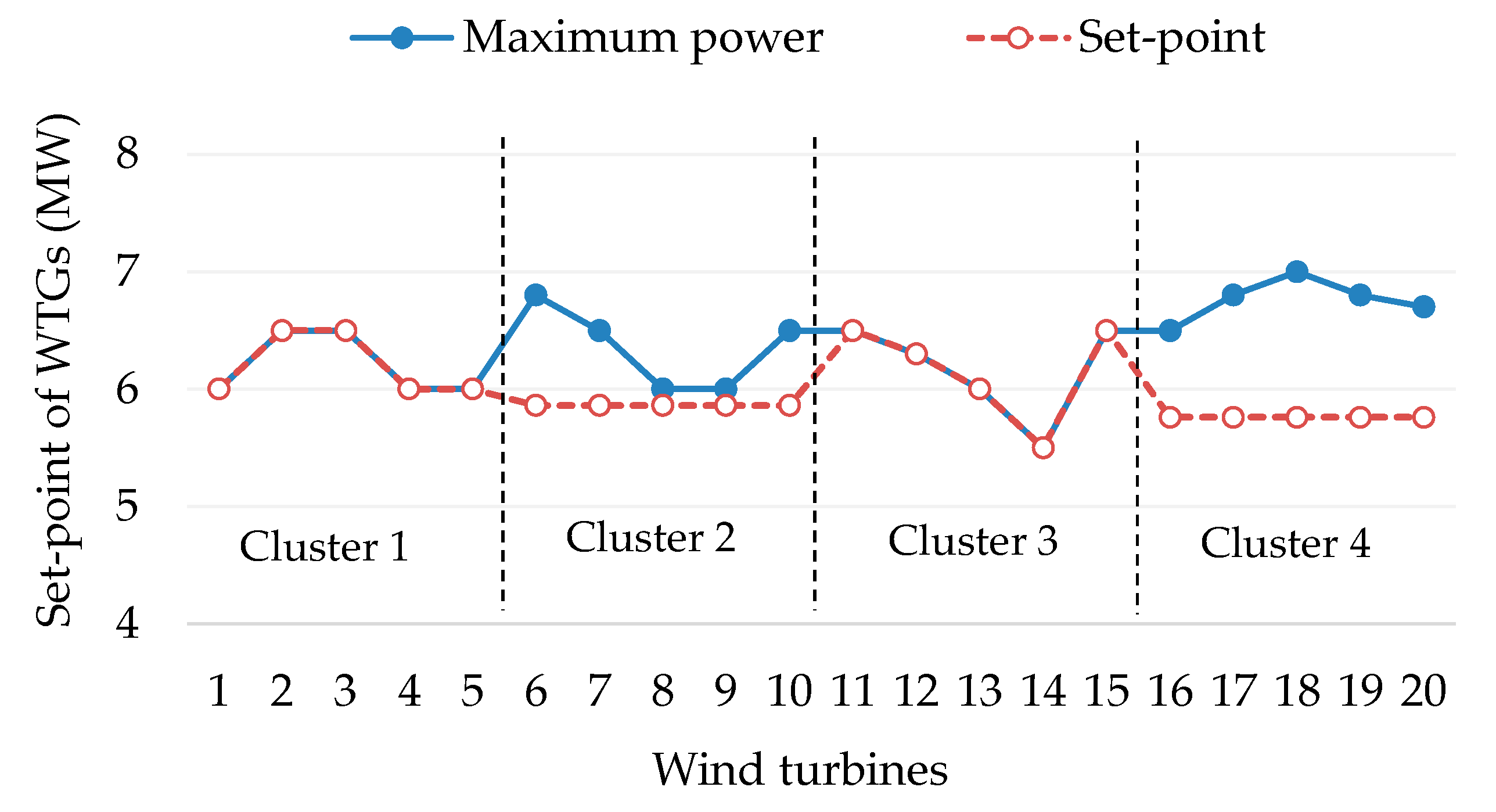
5.3.3. Case 3: WF Changes to Reverse Power Mode at t3 (20% for Reserve Power)

As mentioned in Section 5.2, the WF changed from limited power mode to reserve power mode at t3 with 20% for the requirement of reserve capacity, as shown in Figure 6. At t3, the maximum output power of clusters 1, 2, 3, and 4 are 36.6 MW, 32.5 MW, 31.4 MW, and 31.4 MW, respectively. When TSO changes WF’s operation mode, information-sharing process is also repeated to determine the information of current output power of WF, maximum output power of WF, and required power from TSO, as shown in Figure 12a–c, respectively. The amount of mismatch power between the current output power and the required power is Pmismatch = Preq − Pset = 105.7 − 120 = −14.3 MW. Therefore, in order to maintain the power balance and minimize the change in the set-points of clusters, the output power of each cluster should be equally reduced by 3.575MW. After determining the mismatch power for each cluster, CEMSs will carry out optimization to determine optimal set-points of WTGs. The set-points of WTGs in clusters 1–4 are shown in Figure 13. In this case study, WTGs in clusters 1, 2, 3, and 4 maintain a certain reserve capacity, as shown in Figure 14. The total reserve capacity in WF is always maintained at 20% of the maximum output power (i.e., Pres = 26.4 MW).
In this study, only two events at t2 and t3 are presented. However, the proposed strategy can be applied to any change in WF. By repeating the same process of sharing information in stage 1 and performing local optimization in stage 2, WF can be optimally operation and comply with all requirements from TSO.

6. Conclusions

This paper has proposed a hybrid EMS to manage the operation of a WF system by combining both centralized and decentralized approaches. To optimize the operation of WF, we developed a two-stage optimization strategy to determine the set-points of WTGs and also fulfill grid-code constraints. In stage 1, a diffusion strategy-based information sharing among CEMSs and TSO has been presented to determine the amount of power required from the TSO, the amount of current output power of each cluster, and the amount of maximum output power of each cluster. After the information-sharing process, the amount of power mismatch can be easily found based on current output power and required power. This amount of power mismatch is allocated to all clusters through the CEMSs. In stage 2, an MILP-based optimization model has been developed to optimize the set-points of WTGs inside clusters. Finally, to show the effectiveness of the proposed method, several case studies have been analyzed in detail in the simulation results for the operation of a WF with 20 WTGs divided into four different clusters. It can be concluded that the use of the proposed method helps the operation of WF always comply with the requirements of TSO and also minimizing the power deviation for set-points of WTGs in each cluster. This helps the output power of WTGs smoother and avoid the internal power fluctuation in WF.
In this paper, the clusters are operated by the same owner, therefore the clusters operate cooperatively to satisfy the mismatch power between the required power and the generated power. However, several clusters might be operated by different owners. The economics of clusters in deregulated environments is the main concern in this situation and is also a suitable future extension for this study.

Author Contributions

V.-H.B. designed the experiments and wrote the paper; A.H. and W.-G.L. analyzed the data and carried out the experiments; H.-M.K. analyzed and revised the results.

Funding

This research was supported by Korea Electric Power Corporation (grant no. R18XA03).

Conflicts of Interest

The authors declare no conflict of interest.

Nomenclatures

Abbreviations
CEMSCluster energy management system
EMSEnergy management system
MILPMixed-integer linear programming
MPPTMaximum power point tracking
RESRenewable energy source
TSOTransmission system operator
WFWind farm
WTGWind turbine generator
Sets
TScheduling horizon
NiSet of WTGs
ISet of clusters
Indices
tIndex of intervals
n, mIndex of WTGs
iIndex of clusters
Parameters
AAdjacent matrix for the communication network
xk,iState of agent i at iteration k
s ^ i , k ( ϕ ) Stochastic gradient of intermediate state φ for agent i at iteration k
P n , t r a t e Rated power of WTG n in cluster i
P n , i min Minimum operation point of WTG n in cluster i
P n , t , i a v a i l Available power of WTG n in cluster i at t
s n , t , i State of WTG n in cluster i at t
Δ P t , i Mismatch power from stage 1 of cluster i at t
p Δ t , i Penalty for mismatch power of cluster i at t
p m n , t , i Penalty for power deviation for set-points of WTG m and WTG n in cluster i at t
P D m n , t , i Power deviation for set-points of WTG m and WTG n in cluster i at t
P lim , t Limited power at t
p r e s , t Reserve power at t
P n , i R D Ramp-down rate of WTG n in cluster i
P n , i R U Ramp-up rate of WTG n in cluster i

References

  1. Bull, S.R. Renewable energy today and tomorrow. Proc. IEEE 2001, 89, 1216–1226. [Google Scholar] [CrossRef]
  2. Yaramasu, V.; Wu, B.; Sen, P.C.; Kouro, S.; Narimani, M. High-power wind energy conversion systems: State-of-the-art and emerging technologies. Proc. IEEE 2015, 103, 740–788. [Google Scholar] [CrossRef]
  3. Pao, L.Y.; Johnson, K. Control of wind turbines. IEEE Control Syst. Mag. 2011, 31, 44–62. [Google Scholar]
  4. Fichaux, N.; Singh, G.; Lee, W.J.; Vinci, S. 30 years of policies for wind energy: Lessons from 12 markets. 2012. Available online: https://www.irena.org/DocumentDownloads/Publications/-GWEC_WindReport_All_web%20display.pdf (accessed on 25 November 2019).
  5. Ng, C.; Ran, L. Offshore Wind Farms: Technologies, Design and Operation; Woodhead Publishing: Cambridge, UK, 2016. [Google Scholar]
  6. Tsili, M.; Papathanassiou, S. A review of grid code technical requirements for wind farms. IET Renew. Power Gener. 2009, 3, 308–332. [Google Scholar] [CrossRef]
  7. Abdeltawab, H.H.; Mohamed, Y.A.R.I. Robust energy management of a hybrid wind and flywheel energy storage system considering flywheel power losses minimization and grid-code constraints. IEEE Trans. Ind. Electron. 2016, 63, 4242–4254. [Google Scholar] [CrossRef]
  8. Mohseni, M.; Islam, S.M. Review of international grid codes for wind power integration: Diversity, technology and a case for global standard. Renew. Sustain. Energy Rev. 2012, 16, 3876–3890. [Google Scholar] [CrossRef]
  9. Zhao, H.; Wu, Q.; Wang, J.; Liu, Z.; Shahidehpour, M.; Xue, Y. Combined active and reactive power control of wind farms based on model predictive control. IEEE Trans. Energy Convers. 2017, 32, 1177–1187. [Google Scholar] [CrossRef] [Green Version]
  10. Wang, M.; Mu, Y.; Jia, H.; Wu, J.; Yu, X.; Qi, Y. Active power regulation for large-scale wind farms through an efficient power plant model of electric vehicles. Appl. Energy 2017, 185, 1673–1683. [Google Scholar] [CrossRef]
  11. Ziping, W.U.; Wenzhong, G.A.O.; Tianqi, G.A.O.; Weihang, Y.A.N.; Zhang, H.; Shijie, Y.A.N.; Xiao, W.A.N.G. State-of-the-art review on frequency response of wind power plants in power systems. J. Modern Power Syst. Clean Energy 2018, 6, 1–16. [Google Scholar]
  12. Di Marzio, G.; Eek, J.; Tande, J.O.; Fosso, O.B. Implication of grid code requirements on reactive power contribution and voltage control strategies for wind power integration. In Proceedings of the International Conference on Clean Electrical Power, Capri, Italy, 21–23 May 2007; pp. 154–158. [Google Scholar]
  13. Moawwad, A.; El Moursi, M.S.; Xiao, W. Advanced fault ride-through management scheme for VSC-HVDC connecting offshore wind farms. IEEE Trans. Power Syst. 2016, 31, 4923–4934. [Google Scholar] [CrossRef]
  14. Justo, J.J.; Mwasilu, F.; Jung, J.W. Doubly-fed induction generator based wind turbines: A comprehensive review of fault ride-through strategies. Renew. Sustain. Energy Rev. 2015, 45, 447–467. [Google Scholar] [CrossRef]
  15. Hansen, A.D.; Sørensen, P.; Iov, F.; Blaabjerg, F. Centralised power control of wind farm with doubly fed induction generators. Renew. Energy 2006, 31, 935–951. [Google Scholar] [CrossRef]
  16. De Paola, A.; Angeli, D.; Strbac, G. Scheduling of wind farms for optimal frequency response and energy recovery. IEEE Trans. Control Syst. Technol. 2016, 24, 1764–1778. [Google Scholar] [CrossRef]
  17. Hossain, M.J.; Pota, H.R.; Kumble, C. Decentralized robust static synchronous compensator control for wind farms to augment dynamic transfer capability. J. Renew. Sustain. Energy 2010, 2, 1–20. [Google Scholar] [CrossRef] [Green Version]
  18. Zhong, S.; Wang, X. Decentralized model-free wind farm control via discrete adaptive filtering methods. IEEE Trans. Smart Grid 2016, 9, 2529–2540. [Google Scholar] [CrossRef]
  19. Kristalny, M.; Madjidian, D. Decentralized feedforward control of wind farms: Prospects and open problems. In Proceedings of the 50th IEEE Conference on Decision and Control and European Control Conference, Orlando, FL, USA, 12–15 December 2011; pp. 3464–3469. [Google Scholar]
  20. de Azevedo, R.; Cintuglu, M.H.; Ma, T.; Mohammed, O.A. Multiagent-based optimal microgrid control using fully distributed diffusion strategy. IEEE Trans. Smart Grid 2017, 8, 1997–2008. [Google Scholar] [CrossRef]
  21. Bui, V.H.; Hussain, A.; Kim, H.M. Optimal operation of microgrids considering auto-configuration function using multiagent system. Energies 2017, 10, 1484. [Google Scholar] [CrossRef] [Green Version]
  22. Kong, X.; Liu, X.; Ma, L.; Lee, K.Y. Hierarchical distributed model predictive control of standalone wind/solar/battery power system. IEEE Trans. Syst. Man Cybern. Syst. 2019, 49, 1570–1581. [Google Scholar] [CrossRef]
  23. Xu, Y.; Li, Z. Distributed optimal resource management based on the consensus algorithm in a microgrid. IEEE Trans. Ind. Electron. 2014, 62, 2584–2592. [Google Scholar] [CrossRef]
  24. Bui, V.H.; Hussain, A.; Kim, H.M. Diffusion strategy-based distributed operation of microgrids using multiagent system. Energies 2017, 10, 903. [Google Scholar] [CrossRef] [Green Version]
  25. Sayed, A.H. Adaptive networks. Proc. IEEE 2014, 102, 460–497. [Google Scholar] [CrossRef]
  26. McCarl, B.A.; Spreen, T.H. Applied Mathematical Programming Using Algebraic Systems. Dept. Agricult. Econ., Texas A&M Univ.: College Station, TX, USA; pp. 1–567. Available online: http://agecon2.tamu.edu/people/faculty/mccarlbruce/mccspr/thebook.pdf (accessed on 25 November 2019).
  27. Xu, J.; Yi, X.; Sun, Y.; Lan, T.; Sun, H. Stochastic optimal scheduling based on scenario analysis for wind farms. IEEE Trans. Sustain. Energy 2017, 8, 1548–1559. [Google Scholar] [CrossRef]
  28. Ebrahimi, F.M.; Khayatiyan, A.; Farjah, E. A novel optimizing power control strategy for centralized wind farm control system. Renew. Energy 2016, 86, 399–408. [Google Scholar] [CrossRef]
  29. Guo, Q.; Sun, H.; Wang, B.; Zhang, B.; Wu, W.; Tang, L. Hierarchical automatic voltage control for integration of large-scale wind power: Design and implementation. Electr. Power Syst. Res. 2015, 120, 234–241. [Google Scholar] [CrossRef]
  30. Bui, V.H.; Hussain, A.; Kim, H.M. Optimal operation of wind farm for reducing power deviation considering grid-code constraints and events. IEEE Access 2019, 7, 139058–139068. [Google Scholar] [CrossRef]
  31. IBM ILOG CPLEX V12.6 User’s Manual for CPLEX 2015, CPLEX Division; ILOG: Incline Village, NV, USA, 2015.
Figure 1. The tested WF system: (a) electric power network; (b) communication network.
Energies 12 04672 g001
Figure 2. Operation modes of WF system: (a) limited power constraints; (b) reserve power constraints.
Energies 12 04672 g002
Figure 3. Proposed optimization scheme for operation of WF.
Energies 12 04672 g003
Figure 4. Detailed two-stage operation of WF system: (a) stage 1-sharing information; (b) stage 2-optimization.
Energies 12 04672 g004
Figure 5. Test WF system with detailed rated voltage.
Energies 12 04672 g005
Figure 6. Three case study to test the proposed method.
Energies 12 04672 g006
Figure 7. Optimal set-point of WTGs at t1.
Energies 12 04672 g007
Figure 8. Amount of power reserve at t1.
Energies 12 04672 g008
Figure 9. Information sharing at t2: (a) the current set-point of WF; (b) the maximum output of WF; (c) required power from TSO.
Energies 12 04672 g009
Figure 10. Optimal set-point of WTGs at t2.
Energies 12 04672 g010
Figure 11. Amount of power reserve at t2.
Energies 12 04672 g011
Figure 12. Information sharing at t3: (a) the current set-point of WF; (b) the maximum output of WF; (c) required power from TSO.
Energies 12 04672 g012
Figure 13. Optimal set-point of WTGs at t3.
Energies 12 04672 g013
Figure 14. Amount of power reserve at t3.
Energies 12 04672 g014
Table 1. Maximum output power of WTGs at t1, t2, and t3.
Cluster 1WTG1WTG2WTG3WTG4WTG5Total (MW)
t15.855.56.26.228.7
t266.56.56631
t37.87.27.56.87.536.8
Cluster 2WTG6WTG7WTG8WTG9WTG10-
t15.554.54524
t26.86.5666.531.8
t36.86.26.56.86.232.5
Cluster 3WTG11WTG12WTG13WTG14WTG15-
t16.266.25.55.829.7
t26.56.365.56.530.8
t36.25.56.26.5731.4
Cluster 4WTG16WTG17WTG18WTG19WTG20-
t154.545523.5
t26.56.876.86.733.8
t36.26.566.26.531.4

