1. Introduction
The Gas-insulated Line (GIL) is a power equipment for the electricity transmission at high voltage level, with the conductor kept in the center of the metallic enclosure and SF
6-N
2 gas mixture as the insulating medium [
1]. Especially, due to its insulation-aging resistance, high reliability and little ecological landscape impact, the GIL suitably serves as the connection between power plants and substations and applies to complicated landscapes [
2,
3,
4,
5]. The cost of UHV GIL is more expensive than that of overhead transmission lines, so the GIL-overhead hybrid line is an ideal transmission system for UHV long distance power transmission to ensure both economy and reliability. This hybrid line combination method had been applied to the UHV power transmission project in China—SuTong UHV GIL Pipe Gallery Project.
As the long distance, high voltage level and distributed capacitive current of the UHV transmission line, the conventional distance protection based on lumped parameters cannot be applied. Moreover, the electrical parameters of GIL and overhead transmission line are quite different, so the protective zone of the conventional distance protection will change, further causing maloperation in serious cases. Therefore, it is of great practical significance for enhancing the safety and the stability of the power system to study the distance protection algorithm for UHV GIL-overhead hybrid line.
At present, the distance protection of UHV overhead line is studied, and many results have been achieved. Ref. [
6] proposes a distance protection based on the distributed parameters model and distinguished the internal or external faults via the voltage distribution characteristics. Ref. [
7] presents a distance protection setting method for mutually coupled transmission lines. Ref. [
8] analyzes the defects of the off-line setting scheme of the distance protection and proposes an adaptive setting scheme. Ref. [
9] examines the phase relationship between the negative sequence current at the relaying point and the current at the fault point and then proposes an adaptive distance protection scheme based on the impedance complex plane. Ref. [
10] studies the effects of static var compensator on three zone distance relay protection and proposes an algorithm that utilizes synchronized phasors measurement to enhance the performance of distance protection. Ref. [
11] analyzes the drawbacks of the legacy distance protection in instantaneous fault clearance and proposes a distance algorithm that uses the relay local signals to accelerate the trip for zone-II internal faults. Ref. [
12] compares the sum of currents at the predetermined buses before and after the disturbance, using synchronized current phasor measurements, then proposes a wide-area backup protection algorithm to differentiate the short-circuit faults and other stresses in the power system. Ref. [
13] presents a wide-area backup protection algorithm based on the local and neighboring substation signals. The literatures above provide the solutions with regard to the influence of the distribution capacitance on the distance protection, but the GIL causes variation of line parameters, thus the distance protection methods above cannot be applied to UHV GIL-overhead hybrid line directly.
Considering that there are few technical applications of UHV GIL-overhead hybrid line, the researches on the distance protection for the hybrid line generally point at cable-overhead hybrid line in EHV and lower voltage level. Ref. [
14] studies and summarizes the influences on the fault loop impedance of distance protection caused by the cable-overhead hybrid line. Ref. [
15] studies the non-homogeneity of the hybrid transmission systems and presents a distance protection algorithm for identifying ground faults in transmission systems with cascaded overhead-submarine cable segments. Refs. [
16,
17,
18] examines the effects on the fault currents and protection principle triggered by the multiple-circuit shared tower transmission lines with different voltages and underground cable sections and analyzes its derivation. Ref. [
19] proposes a digital distance protection for cable-overhead hybrid line with the capacitive currents of both overhead and cable segments considered. Ref. [
20] discusses the challenges of calculating the relay input quantities for faults and of determining the fault loop impedances, then provides a protection scheme for the mixed overhead and underground cable lines.
Some distance protections for the cable-overhead hybrid line have been proposed in the literatures above, but all of these papers are deducted on the basis of lumped parameters model merely and lacked the setting scheme for hybrid line.
Considering the distributed capacitance of the UHV GIL-overhead hybrid line, this paper proposes a distance protection algorithm applicable to this hybrid line, presents a setting scheme with the hybrid line parameters considered and further examines the accuracy of this method through simulation in PSCAD.
2. Frequency Domain Lossless Transmission Line Equation of the Transmission Line
Distance protection adopts frequency domain parameters for operation in general, so the frequency domain equations of the transmission line are
where
and
are respectively the voltages and currents at point x (uncertain point need to be calculated),
and
are the voltages and currents at given point
L0 correspondingly.
By omitting the losses of the resistance and conductance, the transmission line can be equivalent to a lossless line, which R and G are equal to zero. Thus, Equation (1) can be rewritten as
Equation (2) can be transformed to Equation (3) according to the Euler Formula
where
It can be seen from Equation (3) that the transmission progress of traveling wave only presents phase variation but not amplitude attenuation because the resistance has been ignored.
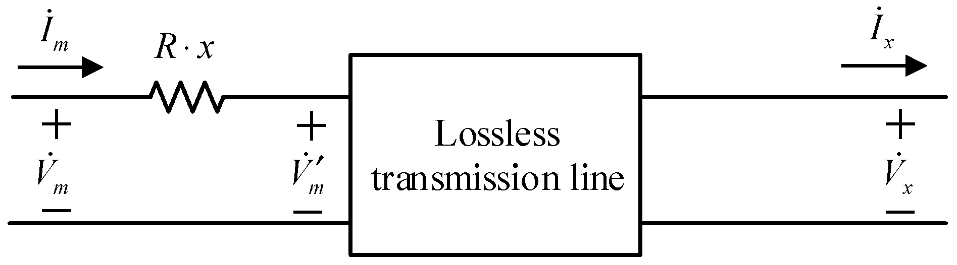
The approximation equivalent above will cause errors in the simulation of long-distance transmission line. Thus, the distributed resistance is considered as a lumped resistance and placed at one end of the line to represent the amplitude attenuation of the voltage and current traveling wave. The diagram of this transmission line model is shown as
Figure 1.
where
,
and
are respectively the voltages at point
m (head end), point
(left end of the lossless line) and point
x (right end of the lossless line),
and
are the currents at point
m and point
x correspondingly. Listing the equations of the voltages and currents in this transmission line model.
The voltages and currents along the transmission line can be calculated approximately according to Equations (5) and (6) and the distance protection algorithm can be deduced by the equations.
3. Distance Protection Based on Lossless Transmission Line Equation
When a fault occurred at point
x, the electrical quantities at point
can be calculated with the data at point
x on the basis of Equation (6).
where
is the voltage at the fault point and
is the current to the left of the fault point. It is noted that Equation (7) reflects the phase variation between the protection installation and the fault point caused by the distribution inductance and capacitance. Therefore, the measured reactance can be obtained by Equation (7).
3.1. Three-Phase Fault
When a three-phase fault occurred, the system remains symmetric and only contains positive sequence components. The positive sequence voltage and current at point
(
,
) can be calculated by Equation (7).
where
and
are respectively the per-unit length positive sequence inductance and capacitance,
and
are the positive sequence voltage at fault point and the positive sequence current to the left of the fault point,
is
Since the voltage at the fault point is zero, Equation (8) can be rewritten as
The line voltage and current between phase A and B at point
(
,
) are
where
,
,
and
are respectively the voltages and currents of phase A and B at point
.
The measured reactance of the lossless line (
) can be obtained by Equation (11).
Similarly, the measured reactance can be calculated with other phase electrical quantities.
3.2. Phase-to-Phase Fault
When a phase-to-phase fault occurred, the system is asymmetric and contains positive and negative sequence components. Taking phase A to phase B short circuit as an example, the voltages and currents of phases A and B at point
(
,
,
,
) can be calculated by Equation (7).
where
,
,
and
are respectively the positive and negative sequence voltages of phase A and B at fault point;
,
,
and
are the positive and negative sequence currents of phase A and B to the left of the fault point.
Subsequently, the line voltage and current between phase A and B at point
(
,
) can be listed as
where
,
are the line voltage at fault point and the line current to the left of the fault point between phase A and B. Since the line voltage at the fault point is zero, Equation (15) can be rewritten as
The measured reactance of the lossless line is
The measured reactance can be calculated with relevant phase electrical quantities in the remaining phase to phase fault.
3.3. Double-Phase-to-Ground Fault
When a double-phase-to-ground fault occurred, the system shows asymmetry and contains positive, negative and zero sequence components. Taking phases A and B to ground short circuit as an example, the measured reactance of the lossless line can be calculated with the same procedure in case B.
The measured reactance can be calculated with relevant phase electrical quantities in the remaining phase to phase to ground fault.
3.4. Single-Phase-to-Ground Fault
When a single-phase-to-ground fault occurred, the system contains positive, negative and zero sequence components. Taking phase A to ground short circuit as an example, the voltage and current of phase A at point
(
,
) can be calculated by Equation (7).
where
and
are the voltage at fault point and the current to the left of the fault point;
and
are the zero sequence voltage and current at point
,
and
are the zero sequence voltage and current at point
calculated by positive sequence parameters, which can be expressed as
where
and
are respectively the per-unit length zero sequence inductance and capacitance,
and
are the zero sequence voltage at fault point and the zero sequence current to the left of the fault point,
is
As the voltage at the fault point is zero, Equation (19) can be rewritten as
On the basis of Equation (6), the zero sequence voltage at fault point can be obtained by
,
,
and
.
By transforming Equation (24):
where
and
are the zero-sequence voltage and current compensation coefficient and can be illustrated as
The measured reactance of the lossless line (
) can be calculated by Equations (21) and (26).
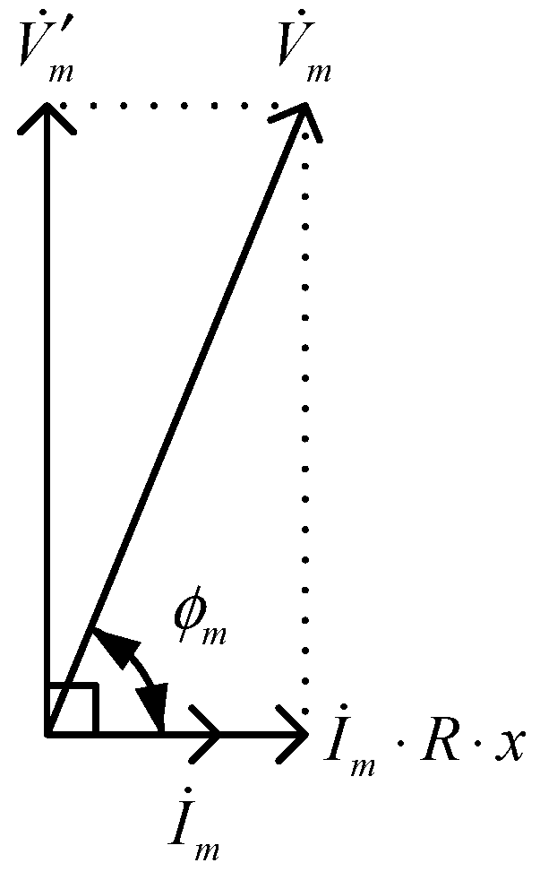
It can be seen from Equations (12), (17), (18) and (27) that the lossless line can be equivalent to a reactance when fault occurred, and the reactance is proportional to the tangent of the fault distance. Therefore, it is possible to determine the fault by calculating the reactance.
According to the deduction above, the phase angle difference between
and
is 90°. The phasor diagram of this transmission line model is shown as
Figure 2.
where
is the phase angle difference between
and
;
is the voltage drop along the lumped resistance. According to the geometric relationship shown in the phasor graph,
is
Then the reactance illustrated in Equations (12), (17), (18) and (27) can be obtained.
4. Setting Scheme of the Hybrid Line
Considering that the inductance of GIL is smaller than overhead transmission line, and the capacitance is larger than overhead transmission line, the measured reactance will decrease when a part of overhead line is replaced by GIL. Therefore, it is essential to study the setting scheme of the hybrid line. Aiming at the overhead-GIL-overhead hybrid line, the protective zone of this hybrid line is shown as
Figure 3.
where , and are the respectively the length of the overhead line 1, GIL and overhead line 2. The zone-I distance relay is set to cover 85% of the entire line, so it might cover the GIL segment. In practice, the setting scheme should be divided into three cases:
If the zone-I distance relay does not cover the GIL segment, the relaying setting should deal with overhead line parameters merely and can be illustrated as
where
l is the length of hybrid line;
and
are the per-unit length positive sequence inductance and capacitance of the overhead line.
If the zone-I distance relay covers a part of the GIL segment, the reactance of the GIL contained in protective zone is
where
is the length of the GIL contained in protective zone;
and
are the per-unit length positive sequence inductance and capacitance of the GIL. Then replacing the GIL (length
) with the overhead line (length
) and keep the reactance on equal.
and
is
The setting value in this case is
If the zone-I distance relay covers entire line of the GIL segment, the setting method is same to the second case:
The zone-II distance relay covers entire line of the GIL segment, so the setting method is same to the third case.
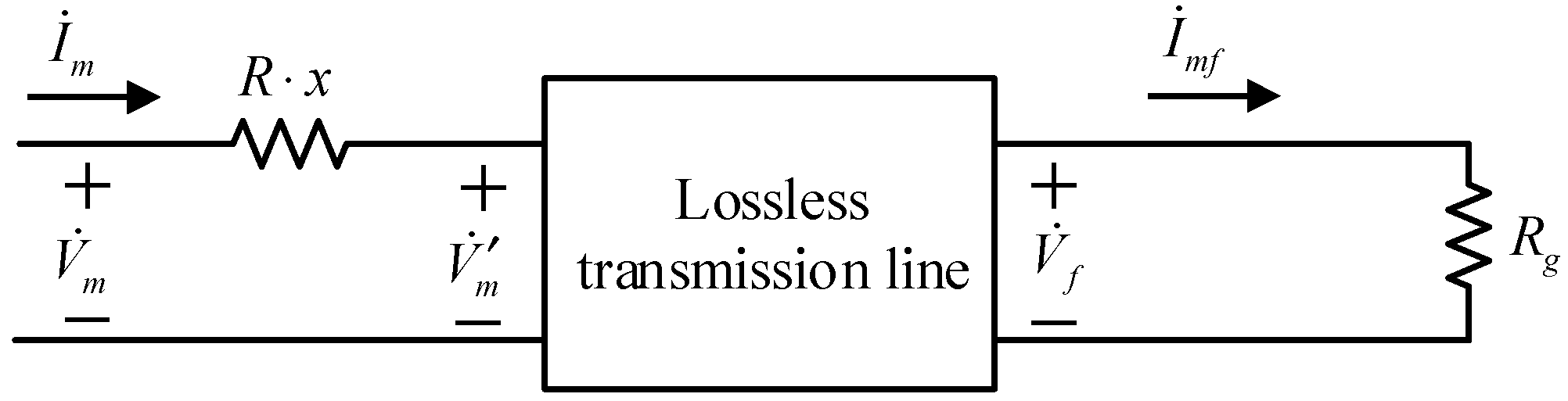
5. Influence of Transition Resistance on Distance Protection Algorithm
When a non-metal fault occurred, the transmission line model in frequency domain is illustrated as
Figure 4.
It is noted that, in
Figure 4, the voltage equation of the right side of the lossless line is
By substituting Equation (35) into Equation (7):
Then calculate the reactance:
Next simplify Equation (37)
In Equation (38), the real part is positive and the positive or negative of the imaginary part is determined by
and
. If
is equal to zero, the right side of Equation (38) is same to that in Equations (12), (17), (18) and (27). The phasor diagram of this condition is shown as
Figure 2.
If
is not equal to zero, the transition resistance
is less than the wave impedance
in general, so the imaginary part of Equation (38) is positive. The phasor diagram of this condition is shown as
Figure 5.
In this distance protection algorithm,
can be obtained by Equation (27). When a non-metal fault occurred, the voltage
calculated through Equation (27) is the voltage
shown in
Figure 5. Then the reactance calculated by
and
includes the imaginary part of Equation (37) merely. That is
By subtracting the reactance in Equation (39) with the reactance without transition resistance:
In Equation (40), the imaginary part is negative. It is indicated that the reactance calculated by this distance protection algorithm will be reduced when a non-metal fault occurred. In some serious cases, such as a non-metal fault located on the next adjacent line, the distance protection will maloperation. Therefore, in this case, the distance protection algorithm above is blocked and shifted to the conventional distance protection algorithm. When a non-metal fault occurred, the phase angle difference between
and
will be reduced, so the distance protection blocking criterion is
According to the simulation test results, θ is set to 80° in this paper to avoid the minimum impedance angle.
6. Simulation Test
PSCAD-based simulations are carried out, and the accuracy of this distance protection is examined. The UHV GIL-overhead hybrid line model is built in this software with three segments: overhead line 1 segment (200 km), GIL segment (60 km) and overhead line 2 segment (80 km). The zone-I distance relay is set to cover 85% of the entire line (289 km). The per-unit length electrical parameters of the overhead line and the GIL are listed in
Table 1.
Different fault types including three phases symmetrical (K1), phase A to ground (K2), phase A and B to ground (K3) and phase A to phase B (K4) are carried out at the middle point of overhead line1 (100 km), GIL (230 km), overhead line 2 (300 km) and the end of the line (340 km). The electrical quantities are brought into the distance protection algorithm to determine whether the fault located in the protective zone (‘+’ denotes the internal fault, ‘−’ denotes the external fault). The simulation results are given in
Table 2.
To test the protective zone of this distance protection, the faults are set at the end of the protective zone. Then adjust the position of the fault point until the zone-II distance relay trigging while the zone-I distance relay does not. They are shown in
Table 3.
In
Table 3, the errors of setting and simulated value are managed within 2%, verifying the accuracy of this distance protection.
The accuracy of the zone-II distance relay is also tested. The simulation results are similar to the zone-I distance relay and no longer listed in this paper.
To verify the accuracy of Equation (41), calculate the phase angle between
and
during normal operation and fault with transition resistance. The simulation results are listed in
Table 4.
Considering that single-phase to ground fault occurred with transition resistance mostly,
Table 4 shows the simulation results in the event of phase A to ground merely. It can be seen from
Table 4 that the phase angle between
and
is reduced when the fault occurred, with normal operation compared. This distance protection can be blocked correctly.


