Abstract
A hybrid air-conditioning system has been proposed by integrating an indirect evaporative pre-cooling unit. In the proposed system, the room exhaust air is employed in the indirect evaporative cooler (IEC) to pre-condition the ambient intake air. The mathematical formulation has been judiciously established for the pre-cooling IEC. The validation of the numerical model has been conducted by comparing the simulated results with the experimental data in terms of the outlet temperature and the heat flux along the heat exchanger surface. The pre-cooling performance of the IEC is theoretically investigated for the climate in representative cities selected from five different climate zones. The psychrometric illustration of the air conditioning variation has indicated that the ambient air can be pre-cooled and pre-dehumidified through the IEC. The possibility of water vapor condensation depends on the humidity ratio of the ambient intake air. The simulation result demonstrates the capability of the pre-cooling IEC to fulfill part of the cooling load of the ambient intake air resulting in a marked energy saving potential.
1. Introduction
World energy consumption by building sector is rapidly increasing in recent years [1]. It is reported that almost half the building energy is consumed by the heating, ventilation, and air-conditioning systems [2]. As a result, the development of novel energy-efficient air-conditioning techniques is getting growing attention to address global energy challenges [3].
Indirect evaporative cooling is considered a promising energy-efficient cooling method [4]. The large latent heat of water evaporation enables the indirect evaporative cooler (IEC) to consume less electricity compared with the mechanical compression system [5].
Previous research works have investigated the performance of the IEC in terms of the heat and mass transfer process [6,7]. Liu et al. [8] and Dizaji et al. [9] presented a numerical model and an analytical model, respectively, for a corrugated dew point evaporative cooler to analyze the influence of varying operation conditions. Duan et al. [10] pointed out that the regenerative IEC was able to reduce the annual electrical consumption by up to 58% based on the analysis for selected locations in China. A dynamic simulation was developed to study the energy performance of a hybrid IEC and direct expansion system [11]. Montazeri et al. [12] conducted a numerical simulation on the water spray system by using Lagrangian–Eulerian approach. Al-Zubaydi and Hong [13] studied the impact of three water spray modes on the performance of IEC. They indicated that the mixed internal and external spray mode shows the best performance in terms of the cooling efficiency and COP (coefficient of performance). Wang et al. [14] developed a numerical model to conduct a comparative study between a regenerative IEC and a conventional IEC. They reported that the regenerative IEC obtained a higher cooling effectiveness, especially at the second stage of the supply air. Pandelidis et al. [15] also conducted a comparative study to investigate the impact of different flow schemes. Shen et al. [16] studied the energy savings for condenser evaporative cooling at 16 locations. The evaporative pre-cooling process was demonstrated as an effective approach to reduce the peak power demand. Jia et al. [17] experimentally investigated a counter-cross-flow IEC for the cooling performance. They pointed out that the dew point effectiveness ranged from 46.7% to 78.6% for the cooler with polystyrene and nylon fiber coated on the plate surface. He et al. [18] developed a numerical model to study the evaporative pre-cooling performance of the cooling towers with two types wetted medium. It was reported that the Cellulose7060 allowed a marked improvement on the cooling efficiency. In addition, an experimental study was carried out to study the air-side flow resistance [19]. Zhu et al. [20] developed an artificial neural network for the calculation of temperature variation of the IEC. The hollow fiber can be integrated with the IEC [21] due to its capability of water vapor permeation [22]. Tariq et al. [23] provided an optimization strategy for regenerative evaporative coolers based on three objective functions. Antonellis et al. [24] conducted an experimental study to investigate the effect of water distribution along the secondary air. The experimental data indicated that the wet-bulb effectiveness can be improved by up to 84% for optimal configurations.
To further promote the application of evaporative cooling technique, novel integrated air-conditioning systems have been proposed in literatures [25,26,27]. Heidari et al. [28] introduced a cooling system by combining desiccant wheels with evaporative coolers for co-production of water and cooling. Zanchini and Naldi [29] studied the application of an evaporative cooling system in North Italy. By coupling the IEC with a refrigeration cycle, the system was able to reduce the reheating energy. Jang et al. [30] evaluated the energy consumption of evaporative dehumidification system by using TRNSYS (TRNSYS 18, Thermal Energy Specialists, LLC, Madison, WI, USA). Simulation results indicated that the dehumidification of hollow fiber membrane was able to reduce 47.6% of the latent load. Narayanan et al. [31] investigated the thermal comfort and the coefficient of performance for a hybrid system based on the solid desiccant and the evaporative cooling system. A better cooling performance was achieved by employing an enthalpy exchanger in tropical climates.
For a conventional IEC, the theoretical lowest supply temperature is limited by the wet-bulb temperature (WBT). Therefore, it is inappropriate for a stand-alone IEC to provide a desired supply air condition in humid climates as a consequence of the high ambient WBT. The IEC has been suggested to be operated as a pre-cooling unit by integrating with a conventional cooling coil [32,33]. The exhaust air from a conditioned space usually has a cooling potential which can be recovered by pre-cooling the intake air through a heat recovery unit. The IEC is able to provide an enhanced heat recovery process by employing the exhaust air as the working air. The ambient air may condense in the product channel when the interface plate temperature is lower than its dew-point temperature. The previous work focused on the process of air flowing along the wall surface with a constant wall temperature [34,35]. However, the present work investigates the humid air condensation in the IEC. The product channel interfacial boundary condition is neither a constant temperature nor a constant heat flux condition. Therefore, the heat and mass transfer in the current pre-cooling IEC is considered more complex. To the best of our knowledge, few research works have carried out an in-depth investigation on the air treatment performance of an evaporative-enhanced precooling IEC for a hybrid air conditioning system under various climate conditions. This work aims to evaluate the cooling effectiveness and the energy saving potential of a pre-cooling IEC by evaporative cooling recovery from the indoor air. We will first introduce the schematic description of the hybrid evaporative pre-cooling system, followed by the development of a mathematical formulation for the pre-cooling IEC. Thereafter, the pre-cooling performance of the IEC will be investigated for five different climate zones. In addition, simulation results are employed to estimate the energy saving potential and the cooling capacity of the pre-cooling IEC.
2. Hybrid Evaporative Pre-Cooling System
Figure 1 shows the proposed schematic diagram of the hybrid air-conditioning system with the integration of a pre-cooling IEC. The conventional air handling unit (AHU) is operated in tandem with the pre-cooling IEC. In this study, the selected IEC has a counter-flow configuration with alternatively arranged dry/wet channels. The exhaust air from the conditioned space is adopted as the working air (WA) flowing through the wet channel. The ambient intake air acts as the product air (PA) in the pre-cooling IEC. Therefore, the working air is cooled by evaporative cooling, which subsequently cools the outdoor air flowing in the adjacent product channels. In addition, the pre-cooling IEC can be performed with a heat recovery function. It is able to pre-condition the ambient air and recover the cooling potential of the indoor air. When the ambient climate is humid, the dew point temperature of the ambient air may be higher than the interface temperature in the pre-cooling IEC due to the cooling potential of the exhaust air. The PA may have a possibility to condense water vapor in the product channel. As a result, the pre-cooling IEC shows a complicated coupled heat and mass transfer process.
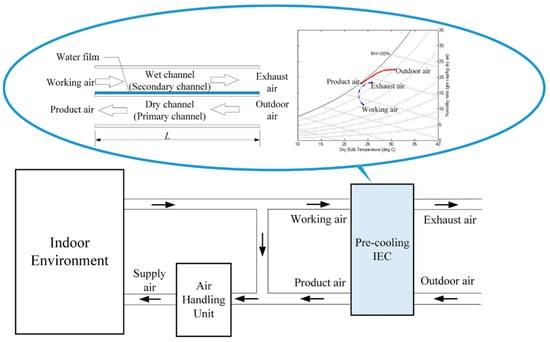
Figure 1.
Schematic of the hybrid system with the integration of a pre-cooling IEC.
3. Mathematical Model
To theoretically investigate the pre-cooling performance of the IEC, a mathematical model is developed. Figure 2 illustrates the computational element.
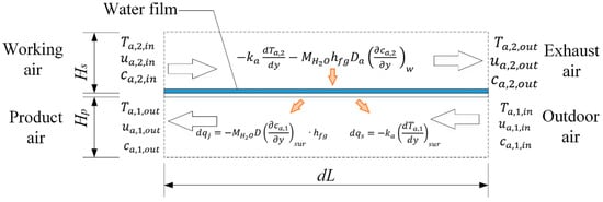
Figure 2.
Description of the calculation element of the pre-cooling IEC.
For the air under steady state, following key governing equations are
For the water vapor in the air stream, the diffusion equation is written as
The working air is able to absorb heat as a consequence of vaporizing water in the working channel. The water vapor concentration gradient is the driving force for mass and latent heat transfer. The water in the working channel is assumed as a thin layer on the channel surface. The water vapor concentration at the interface can be determined as
In the working channel, the interfacial boundary condition at the channel surface is expressed as
In the product channel, the heat and mass transfer process of the PA is impacted by the interfacial plate temperature. When the interface DBT () is higher than the dew point temperature of the PA (), the humidity ratio of the PA keeps constant without moisture condensation. Therefore, in this condition, the sensible cooling process occurs in the product channel resulting in a temperature decrease along the flow direction. When decreases below , the water vapor in the air starts to condense on the cold plate surface. As a result, the concentration of water vapor on the product channel surface is determined as
The condensation rate can be expressed as
The boundary conditions at the product channel interface can be given as
The inlet boundary condition of the product air is
The inlet boundary condition of the working air is
The outlet boundary condition of the product air is
The outlet boundary condition of the system is
The overall heat transfer coefficient for the IEC can be expressed as [36]
To cooling capacity of the IEC is defined as
The total cooling load of the ambient intake air is given as
In this study, the software of COMSOL Multiphysics platform (COMSOL Multiphysics 4.3b, COMSOL, Inc., Burlington, MA, USA) [37] was employed to establish and solve the governing equations. The temperature and velocity fields are calculated in the conjugate heat transfer module, while the concentration field is studied in the transport of diluted species module. The heat and mass transfer process is investigated by coupling the two physical modules simultaneously.
4. Results and Discussion
4.1. Validation of Mathematical Modeling
The numerical model was validated based on two experimental studies. Firstly, the simulated sensible cooling performance was compared with the experimental data for a counter-flow regenerative IEC presented in our previous published work [38]. A lab-scale IEC prototype was constructed for the experimental setup. The inlet air condition was regulated to maintain a desired steady state. The PA in the IEC was sensibly cooled without moisture condensation. The outlet air condition was measured and recorded during the experiment. Figure 3 illustrates the comparison process in terms of the outlet air DBT (dry-bulb temperature) for the IEC. The numerical simulation results showed a maximum discrepancy of about 8% for evaluating the sensible cooling process of the IEC.
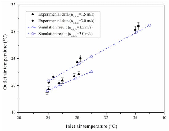
Figure 3.
Validation 1: Outlet air dry bulb temperature of a counter-flow regenerative IEC.
Secondly, the validation was carried out with regard to the moisture condensation from the humid air stream. The relationship between the moisture fraction and the heat flux has been investigated by previous literatures [34,35]. The present mathematical model was compared with a previous experimental study [34] and a numerical study [35] as illustrated in Figure 4. The parameters of and represents the sensible heat flux and the vapor condensation heat flux, respectively. The heat flux was determined under varying water vapor mass fraction difference (). The present mathematical model agrees well with the previous numerical study reported by Volchkov et al. [35] with an average discrepancy of around 3%. The comparison between the present model and the experimental data [34] indicates an average discrepancy of 9.7%. The reason for this violation may be attributed to the fact that the generation of liquid film on the wall surface affecting the heat and mass transfer process. The interface temperature is one of the key parameters for condensation. However, it is reported that the precise interface temperature is difficult to obtain from experimental observation. In this study, we have neglected the waviness of condensation film flow. The average discrepancy between the present mathematical model and the previous experimental data is acceptable in terms of the model’s predictability.
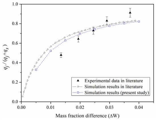
Figure 4.
Validation 2: Water vapor condensation determined by the present mathematical model, previous simulation results [35], and experimental data [34].
In sum, by considering the validation process of these two parts, we have demonstrated the capability of the present mathematical model to analyze the performance of IEC as a pre-cooling device with moisture condensation in the PA channel.
4.2. Temperature and Humidity Ratio Distributions
The cooling performance of the IEC is highly dependent on the climate conditions. The present study investigates the pre-cooling performance under different climate zones. According to the classification of ASHRAE standard [39], the world climates are divided into different zones. The current study has selected five cities (namely, Singapore, Cairo, Firenze, Athinai, and Xi’an) as representative locations from five categories of climate zones. Table 1 indicates the climate zones and the design conditions for the selected locations. The design conditions are based on annual percentiles of 0.4% wet-bulb temperature and mean coincident dry bulb temperature.

Table 1.
Climate zones and design conditions for the selected locations.
The IEC is able to achieve the evaporative pre-cooling function combined with heat recovery effect. The mathematical model is first employed to analyze the air treatment conditions in the IEC channels. Figure 5 and Figure 6 present the condition variation of the PA along the flowing passages in terms of its temperature and humidity ratio, respectively. The inlet condition of the PA was maintained as the design condition of five selected cities, while the exhaust air from the space was adopted as the WA with an inlet condition of 24 °C dry bulb temperature and 60% RH. In the present study, the inlet velocity of both product air and working air was maintained as 2 m/s. It can be seen from Figure 5 that the PA temperature steadily decreases as air passes through the flowing channel. It is further observed from Figure 6 that the PA humidity ratio profile can be divided into two regions. In the first region (dry region), namely, near the entrance of the product channel, the PA humidity ratio is kept constant. It indicates that the PA is sensibly cooled without moisture condensation. In the second region (wet region), the PA humidity ratio starts to decrease once the plate temperature reaches the PA’s dew-point temperature resulting in the condensation of water vapor. Therefore, the PA is dehumidified and cooled simultaneously along the flow direction in the product channel.
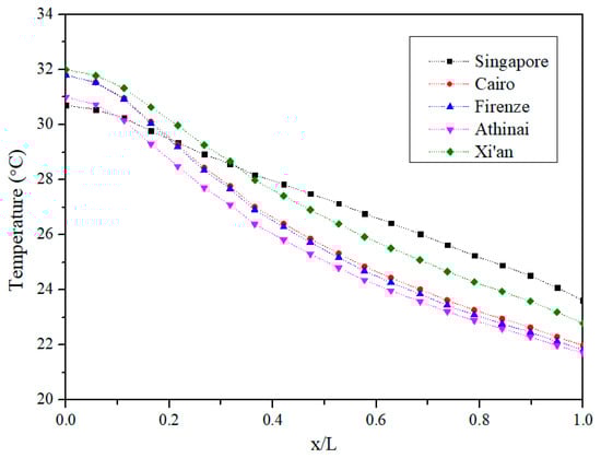
Figure 5.
Product air temperature distributions in the pre-cooling IEC.
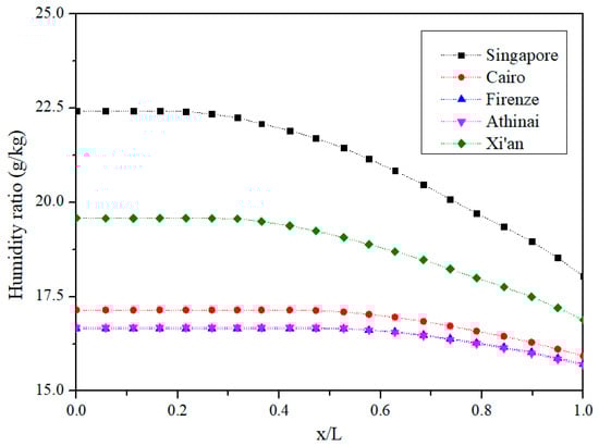
Figure 6.
Product air humidity ratio distributions in the pre-cooling IEC.
It is also observed that the wet region occupies a larger proportion for the PA with a higher inlet humidity ratio. For example, the moisture starts to condense in the channel at the location of x/L = 0.22 for the design condition of Singapore, while the wet region starts at the location of x/L = 0.58 for the climate of Athinai. In other words, the pre-cooling IEC shows a larger latent cooling capacity for humid climates.
4.3. Pre-Cooling Performance
Figure 7 shows the average hourly statistics for dry bulb temperature and relative humidity of the month that the cooling design day lands on. Singapore is a city featuring a hot and humid climate. The average hourly relative humidity in Singapore is the highest among the five cities. The climate of Cairo is hot and dry with a highest average dry bulb temperature of 33.7 °C and a lowest average relative humidity of 36% at 3 pm for the cooling month of July. Firenze, Athinai, and Xi’an are the cities in the warm-humid climate zone, warm-dry climate zone, and mixed-dry climate zone, respectively.
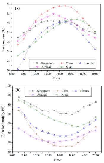
Figure 7.
Average hourly statistics for (a) dry bulb temperature and (b) relative humidity in cooling months of various climates.
The simulation has been carried out to investigate the air treatment process of the pre-cooling IEC in cooling seasons for the selected cities. Figure 8 presents the variation of the average hourly outlet PA temperature of the pre-cooling IEC. In general, the outlet pre-cooling temperature shows a similar trend to the profile of the hourly ambient dry bulb temperature. To further illustrate the latent cooling performance, Figure 9 compares the difference between the dry bulb temperature of the outlet PA and the dew point temperature of the inlet PA (namely, ). The moisture condensation process is triggered when the temperature of PA is lower than the value of . Therefore, the temperature difference () in Figure 9 can be employed as an index for evaluating whether the latent cooling has occurred.
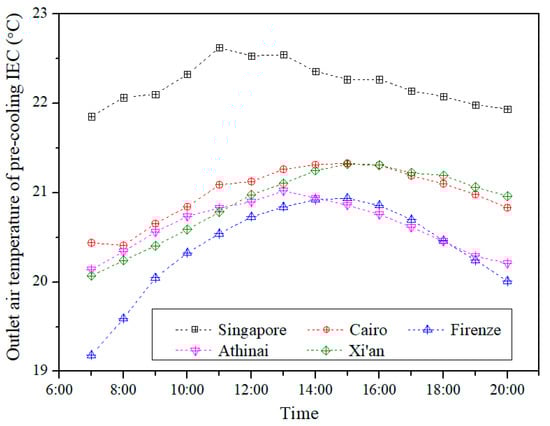
Figure 8.
Outlet air temperature of pre-cooling IEC on design days of various climates.
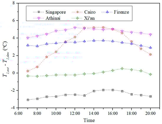
Figure 9.
Comparison between the outlet air temperature and the inlet dew point temperature.
In Singapore, the pre-cooling IEC obtains the highest outlet temperature as a result of the humid climate. The outlet temperature of the pre-cooled PA ranges from 21.9 °C to 22.6 °C. On average, the is around 2.5 °C lower than the . Therefore, the PA is pre-cooled and dehumidified by the IEC throughout the day under the humid tropical climate. In Cairo, the pre-cooling IEC is able to effectively reduce the PA dry bulb temperature since the ambient climate is hot and dry. The pre-cooling IEC purely provides the sensible cooling since the is higher than the . Compared with the variation of in Cairo, the similar profiles are also observed in Firenze and Athinai as shown in Figure 8 and Figure 9. In Xi’an, the average hourly ambient dew point temperature ranges from 20.4 °C to 21.3 °C during the daytime. It can be seen from Figure 8 that the pre-cooling IEC is capable of reducing the dry bulb temperature of the pre-cooled PA below the ambient dew point temperature.
In sum, the pre-cooling IEC is able to provide both sensible and latent cooling capacity for humid climate such as Singapore. In addition, the pre-cooling IEC can also effectively achieve sensible cooling effect for dry climates such as Cairo and Athinai.
4.4. Psychrometric Illustration of the Hybrid Air Cooling Process
Figure 10 employs the psychrometric chart to show an example of the variation of the air conditions by using the pre-cooling IEC. In this example, the ambient air (Point A) is assumed at the design condition of Singapore, while the point W represents the condition of the indoor air.
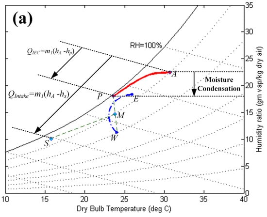
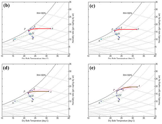
Figure 10.
Description of air conditions on psychrometric chart for the hybrid system operating under the design conditions of (a) Singapore, (b) Cairo, (c) Firenze, (d) Athinai, and (e) Xi’an.
The indoor air is adopted as the working air to absorb heat and water vapor in the working channel. The ambient air temperature is gradually decreased in the product channel. In addition, the humidity ratio of the PA is also reduced when the air dry bulb temperature reaches the dew point temperature. As a result, the condition of PA is changed from point A to point P. The working air is heated and humidified leading to a condition variation from point W to point E. In this example, the ambient intake air fraction is assumed to be 50%. Thereafter, the pre-cooled PA is mixed with the indoor air. The mixed air (at point M) can be further treated through the cooling coil to obtain the supply air condition at point S.
As shown in Figure 10, the enthalpy of the ambient air can be reduced from to by passing through the IEC. The cooling capacity of the IEC () can be determined based on the enthalpy difference. On the other hand, the total cooling load for conditioning the intake ambient air () is calculated according to the enthalpy difference between point A and point S.
4.5. Cooling Capacity and Energy Saving Potential
The cooling capacity of the IEC has been evaluated for the average statistical climate condition in cooling seasons for the selected cities. Figure 11 illustrates the percentage of IEC pre-cooling capacity based on design day conditions. The inlet air of the IEC is assumed as the ambient condition described in Figure 7.
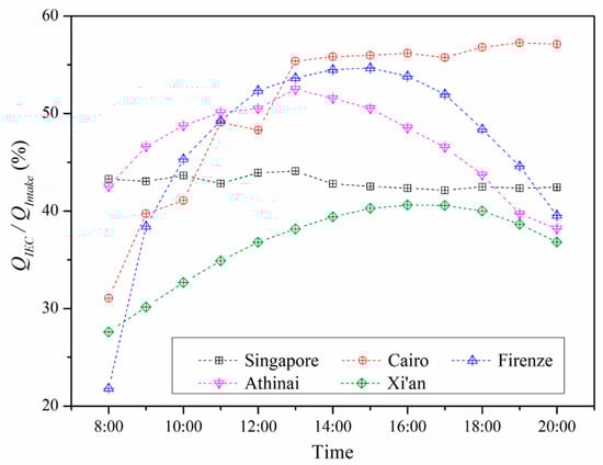
Figure 11.
The percentage between the IEC pre-cooling capacity and the total cooling load for the ambient air.
The ambient intake air is first pre-cooled through the IEC. The IEC pre-cooling capacity is determined as , in which and are the enthalpy of the ambient air and the enthalpy of the pre-cooled air, respectively. The pre-cooled air is then processed through the cooling coil in order to achieve a desired supply air condition. Therefore, the total cooling load for the ambient air is calculated as , in which is the enthalpy of the supply air. In this study, the supply air is assumed at the condition of 16 °C dry bulb temperature and 95% RH. The percentage of IEC pre-cooling capacity is evaluated as .
It can be seen from Figure 11 that the IEC is able to effectively fulfill part of the cooling load of the ambient intake air. In Singapore, the IEC pre-cooling capacity shows a small variation during the daytime with an average percentage of 43%. In Cairo, the IEC has a highest pre-cooling capacity percentage of up to 57%. It demonstrates that the IEC obtains a better pre-cooling performance in hot and dry climate. For the warm climate zone, such as Firenze and Athinai, the percentage of IEC pre-cooling capacity generally presents a higher value compared with the performance in Singapore with the humid climate. In Firenze and Athinai, the average IEC pre-cooling capacity percentage is around 47%. In Xi’an, the percentage spans 28% to 41% for the average ambient climate condition.
In sum, the calculated percentage of IEC pre-cooling capacity has demonstrated the ability of the IEC to handle a part of the cooling load of the ambient intake air. It is worth noting that the COP of the energy efficient IEC is reported to be as high as 14.2 [40]. The COP of a conventional chiller ranges from 2 to 4 [4]. The energy saving potential is achieved due to the energy-efficient method for conditioning the outdoor air flow. As a result, the pre-cooling IEC is able to reduce the energy consumption for the outdoor intake air by up to 38% for Singapore, 49% for Cairo, 47% for Firenze, 45% for Athinai, and 35% for Xi’an, respectively.
5. Conclusions
The performance of an evaporative-enhanced pre-cooling IEC for a hybrid air conditioning system has been investigated under various climate conditions. A mathematical model has been developed to study the complex heat and mass transfer process in the current pre-cooing IEC. The temperature and humidity profiles of the intake air were determined to illustrate the variation of the product air stream conditions through the pre-cooling IEC. The performance of the IEC has been evaluated under the average hourly climate condition in representative cooling month for five different climatic zones. Simulation results have indicated that the proposed pre-cooling IEC is able to fulfill up to 57% of the fresh air cooling load. The energy saving potential can be achieved due to the integration of the energy-efficient IEC. The application of pre-cooling IEC can be easily integrated to new or existing air-conditioning systems. The proposed hybrid system requires additional space for the IEC equipment resulting in a potential limitation. The compact design of the hybrid air-conditioning system is suggested to be a part of the future work.
Author Contributions
Conceptualization, X.C. and L.J.; Methodology, X.C. and S.Z.; Writing—original draft preparation, L.S. and S.Z.; Writing—review and editing, X.C. and L.J.
Funding
This research was funded by the Fundamental Research Funds for the Central Universities (xjj2018074), and China Postdoctoral Science Foundation (2018M631153).
Conflicts of Interest
The authors declare no conflict of interest.
Nomenclature
| α | thermal diffusivity (m2/s) |
| c | molar concentration (mol/m3) |
| cpa | specific heat of moist air (kJ/(kg·°C)) |
| D | diffusivity (m2/s) |
| h | specific enthalpy (kJ/kg) |
| hfg | specific latent heat of water evaporation (kJ/kg) |
| k | thermal conductivity (kW/(m·°C)) |
| L | length of the channel (m) |
| m | mass flow rate of air (kg/s) |
| M | molar mass (kg/mol) |
| Nu | Nusselt number |
| P | pressure (kPa) |
| q | heat flux (kW/m2) |
| Q | heat transfer rate (kW) |
| R | ideal gas constant (J/(K·mol)) |
| T | temperature (°C) |
| u | velocity in x direction(m/s) |
| v | velocity in y direction (m/s) |
| ω | humidity ratio (g moisture/kg dry air) |
| W | mass transfer rate (kg/s) |
| Subscript | |
| 1 | product air (primary air) |
| 2 | working air (secondary air) |
| a | air |
| dew | dew-point temperature |
| in | inlet |
| j | condensation |
| l | latent |
| out | outlet |
| s | sensible |
| sat | saturated |
| sur | surface |
| w | water |
| Abbreviations | |
| RH | relative humidity |
| PA | product air |
| WA | working air |
| DBT | dry-bulb temperature |
| WBT | wet-bulb temperature |
References
- Do, S.L.; Baltazar, J.C.; Haberl, J. Potential cooling savings from a ground-coupled return-air duct system for residential buildings in hot and humid climates. Energy Build. 2015, 103, 206–215. [Google Scholar] [CrossRef]
- Chua, K.J.; Chou, S.K.; Yang, W.M.; Yan, J. Achieving better energy-efficient air conditioning—A review of technologies and strategies. Appl. Energy 2013, 104, 87–104. [Google Scholar] [CrossRef]
- Papakostas, K.T.; Tsamitros, A.; Martinopoulos, G. Validation of modified one-dimensional models simulating the thermal behavior of earth-to-air heat exchangers—Comparative analysis of modelling and experimental results. Geothermics 2019, 82, 1–6. [Google Scholar] [CrossRef]
- Duan, Z.; Zhan, C.; Zhang, X.; Mustafa, M.; Zhao, X.; Alimohammadisagvand, B.; Hasan, A. Indirect evaporative cooling: Past, present and future potentials. Renew. Sustain. Energy Rev. 2012, 16, 6823–6850. [Google Scholar] [CrossRef]
- Cuce, P.M.; Riffat, S. A state of the art review of evaporative cooling systems for building applications. Renew. Sustain. Energy Rev. 2016, 54, 1240–1249. [Google Scholar] [CrossRef]
- Sadighi Dizaji, H.; Hu, E.J.; Chen, L. A comprehensive review of the Maisotsenko-cycle based air conditioning systems. Energy 2018, 156, 725–749. [Google Scholar] [CrossRef]
- Wan, Y.; Ren, C.; Xing, L. An approach to the analysis of heat and mass transfer characteristics in indirect evaporative cooling with counter flow configurations. Int. J. Heat Mass Transf. 2017, 108, 1750–1763. [Google Scholar] [CrossRef]
- Liu, Y.; Li, J.M.; Yang, X.; Zhao, X. Two-dimensional numerical study of a heat and mass exchanger for a dew-point evaporative cooler. Energy 2019, 168, 975–988. [Google Scholar] [CrossRef]
- Sadighi Dizaji, H.; Hu, E.J.; Chen, L.; Pourhedayat, S. Development and validation of an analytical model for perforated (multi-stage) regenerative M-cycle air cooler. Appl. Energy 2018, 228, 2176–2194. [Google Scholar] [CrossRef]
- Duan, Z.; Zhao, X.; Zhan, C.; Dong, X.; Chen, H. Energy saving potential of a counter-flow regenerative evaporative cooler for various climates of China: Experiment-based evaluation. Energy Build. 2017, 148, 199–210. [Google Scholar] [CrossRef]
- Duan, Z.; Zhao, X.; Liu, J.; Zhang, Q. Dynamic simulation of a hybrid dew point evaporative cooler and vapour compression refrigerated system for a building using EnergyPlus. J. Build. Eng. 2019, 21, 287–301. [Google Scholar] [CrossRef]
- Montazeri, H.; Blocken, B.; Hensen, J.L.M. Evaporative cooling by water spray systems: CFD simulation, experimental validation and sensitivity analysis. Build. Environ. 2015, 83, 129–141. [Google Scholar] [CrossRef]
- Al-Zubaydi, A.Y.T.; Hong, G. Experimental study of a novel water-spraying configuration in indirect evaporative cooling. Appl. Therm. Eng. 2019, 151, 283–293. [Google Scholar] [CrossRef]
- Wang, Y.; Huang, X.; Li, L. Comparative study of the cross-flow heat and mass exchangers for indirect evaporative cooling using numerical methods. Energies 2018, 11, 3374. [Google Scholar] [CrossRef]
- Pandelidis, D.; Anisimov, S.; Rajski, K.; Brychcy, E.; Sidorczyk, M. Performance comparison of the advanced indirect evaporative air coolers. Energy 2017, 135, 138–152. [Google Scholar] [CrossRef]
- Shen, B.; New, J.; Ally, M. Energy and Economics Analyses of Condenser Evaporative Precooling for Various Climates, Buildings and Refrigerants. Energies 2019, 12, 2079. [Google Scholar] [CrossRef]
- Jia, L.; Liu, J.; Wang, C.; Cao, X.; Zhang, Z. Study of the thermal performance of a novel dew point evaporative cooler. Appl. Therm. Eng. 2019, 160, 114069. [Google Scholar] [CrossRef]
- He, S.; Xu, Y.; Zhang, G.; Hooman, K.; Gao, M. Selection of wetted media for pre-cooling of air entering natural draft dry cooling towers. Appl. Therm. Eng. 2017, 114, 857–863. [Google Scholar] [CrossRef]
- He, S.; Zhang, Z.; Gao, M.; Sun, F.; Lucas, M.; Hooman, K. Experimental study on the air-side flow resistance of different water collecting devices for wet cooling tower applications. J. Wind Eng. Ind. Aerodyn. 2019, 190, 53–60. [Google Scholar] [CrossRef]
- Zhu, G.; Chow, T.T.; Lee, C.K. Performance analysis of counter-flow regenerative heat and mass exchanger for indirect evaporative cooling based on data-driven model. Energy Build. 2017, 155, 503–512. [Google Scholar] [CrossRef]
- Chen, X.; Su, Y.; Aydin, D.; Zhang, X.; Ding, Y.; Reay, D.; Law, R.; Riffat, S. Experimental investigations of polymer hollow fibre integrated evaporative cooling system with the fibre bundles in a spindle shape. Energy Build. 2017, 154, 166–174. [Google Scholar] [CrossRef]
- Lim, K.; An, H.; Wang, P.; Liu, G.; Yu, S. Theoretical and Computational Analysis on Double-End Submerged Hollow Fibre Membrane Modules. Energies 2018, 11, 1042. [Google Scholar] [CrossRef]
- Tariq, R.; Sohani, A.; Xamán, J.; Sayyaadi, H.; Bassam, A.; Tzuc, O.M. Multi-objective optimization for the best possible thermal, electrical and overall energy performance of a novel perforated-type regenerative evaporative humidifier. Energy Convers. Manag. 2019, 198, 111802. [Google Scholar] [CrossRef]
- De Antonellis, S.; Joppolo, C.M.; Liberati, P. Performance measurement of a cross-flow indirect evaporative cooler: Effect of water nozzles and airflows arrangement. Energy Build. 2019, 184, 114–121. [Google Scholar] [CrossRef]
- Cui, X.; Islam, M.R.; Mohan, B.; Chua, K.J. Theoretical analysis of a liquid desiccant based indirect evaporative cooling system. Energy 2016, 95, 303–312. [Google Scholar] [CrossRef]
- Bui, D.T.; Kum Ja, M.; Gordon, J.M.; Ng, K.C.; Chua, K.J. A thermodynamic perspective to study energy performance of vacuum-based membrane dehumidification. Energy 2017, 132, 106–115. [Google Scholar] [CrossRef]
- Islam, M.R.; Jahangeer, K.A.; Chua, K.J. Experimental and numerical study of an evaporatively-cooled condenser of air-conditioning systems. Energy 2015, 87, 390–399. [Google Scholar] [CrossRef]
- Heidari, A.; Roshandel, R.; Vakiloroaya, V. An innovative solar assisted desiccant-based evaporative cooling system for co-production of water and cooling in hot and humid climates. Energy Convers. Manag. 2019, 185, 396–409. [Google Scholar] [CrossRef]
- Zanchini, E.; Naldi, C. Energy saving obtainable by applying a commercially available M-cycle evaporative cooling system to the air conditioning of an office building in North Italy. Energy 2019, 179, 975–988. [Google Scholar] [CrossRef]
- Jang, J.; Kang, E.C.; Lee, H.K.; Jeong, S.; Park, S.R. Energy demand comparison between hollow fiber membrane based dehumidification and evaporative cooling dehumidification using trnsys. Energies 2018, 11, 1181. [Google Scholar] [CrossRef]
- Narayanan, R.; Halawa, E.; Jain, S. Dehumidification Potential of a Solid Desiccant Based Evaporative Cooling System with an Enthalpy Exchanger Operating in Subtropical and Tropical Climates. Energies 2019, 12, 2704. [Google Scholar] [CrossRef]
- Cui, X.; Chua, K.J.; Islam, M.R.; Ng, K.C. Performance evaluation of an indirect pre-cooling evaporative heat exchanger operating in hot and humid climate. Energy Convers. Manag. 2015, 102, 140–150. [Google Scholar] [CrossRef]
- Chen, Y.; Yang, H.; Luo, Y. Indirect evaporative cooler considering condensation from primary air: Model development and parameter analysis. Build. Environ. 2016, 95, 330–345. [Google Scholar] [CrossRef]
- Takarada, M.; Ikeda, S.; Izumi, M. Forced convection, and heat and mass transfer from humid air under condensation conditions. In Proceedings of the Proceedings of Experimental Heat Transfer, Fluid Mechanics and Thermodynamics, Brussels, Belgium, 2–6 June 1997; pp. 1103–1116. [Google Scholar]
- Volchkov, E.P.; Terekhov, V.V.; Terekhov, V.I. A numerical study of boundary-layer heat and mass transfer in a forced flow of humid air with surface steam condensation. Int. J. Heat Mass Transf. 2004, 47, 1473–1481. [Google Scholar] [CrossRef]
- Cui, X.; Chua, K.J.; Islam, M.R.; Yang, W.M. Fundamental formulation of a modified LMTD method to study indirect evaporative heat exchangers. Energy Convers. Manag. 2014, 88, 372–381. [Google Scholar] [CrossRef]
- COMSOL Multiphysics Reference Manual; COMSOL 4.3b.; COMSOL, Inc.: Burlington, MA, USA, 2013.
- Cui, X.; Islam, M.R.; Mohan, B.; Chua, K.J. Developing a performance correlation for counter-flow regenerative indirect evaporative heat exchangers with experimental validation. Appl. Therm. Eng. 2016, 108, 774–784. [Google Scholar] [CrossRef]
- ASHRAE. ASHRAE Handbook-Fundamentals; ASHRAE Inc.: Atalanta, GA, USA, 2009. [Google Scholar]
- Jradi, M.; Riffat, S. Experimental and numerical investigation of a dew-point cooling system for thermal comfort in buildings. Appl. Energy 2014, 132, 524–535. [Google Scholar] [CrossRef]
© 2019 by the authors. Licensee MDPI, Basel, Switzerland. This article is an open access article distributed under the terms and conditions of the Creative Commons Attribution (CC BY) license (http://creativecommons.org/licenses/by/4.0/).