Article

Prediction of PWM-Induced Current Ripple in Subdivided Stator Windings Using Admittance Analysis

1
GeePs|Group of Electrical Engineering—Paris, CNRS, CentraleSupélec, University Paris-Sud, Université Paris-Saclay, Sorbonne Université, 3 & 11 rue Joliot-Curie, Plateau de Moulon 91192 Gif-sur-Yvette CEDEX, France
2
SATIE|Systèmes et Applications des Technologies de l’Information et de l’Energie, ENS Paris-Saclay, CNRS, Université Paris-Saclay, 94235 Cachan, France
*
Author to whom correspondence should be addressed.
Energies 2019, 12(23), 4418; https://doi.org/10.3390/en12234418
Submission received: 30 September 2019 / Revised: 25 October 2019 / Accepted: 28 October 2019 / Published: 21 November 2019
(This article belongs to the Special Issue Control of Multiphase Machines and Drives)

Abstract

:
Subdividing stator winding is a way to lower the DC link voltage value in electric drives and reduce the stress on motor insulation. Coupled windings sharing the same stator teeth are modelled in order to evaluate the link between voltages disparities and current ripple. This paper provides an assessment of current ripple rise in the subdivided windings compared to ordinary topologies through the use of a basic inductive model. A method for PWM-Induced current ripple and high-frequency loss estimation based on admittance measurements is developed and experimentally validated. The use of this subdivided structure does not induce more than a 10% rise of the PWM-induced current ripple compared to a standard winding structure.

1. Introduction

Sizing of electrical powertrains in transportation applications must deal with severe size and mass constraints [1]. Increasing the switching frequency appears to be a solution to improve power integration as it permits smaller passive components [2]. The high slew rate of GaN or SiC-based switches enables the high switching frequencies required although a trade-off between low switching losses and high electromagnetic interferences must be considered [3,4]. In electric drive applications, high dv/dt rates may cause insulation degradation [5,6] and bearing wear [7] leading to a shorter lifetime. Traction chains in electric vehicles (EV) are supplied by a DC bus usually operating in a voltage range of between 300 V and 600 V [1]. DC-link voltage reduction can be investigated to reduce insulation stress and the cost of DC-bus capacitors [8]. Reconfiguration of windings can extend the rated power or the speed range for a given DC-link voltage value [9,10]. Such a change in motor windings may also improve fault tolerance [11,12].Using a drive DC voltage of under 60 V is recognised by international safety certifications (such as CE mark) as reducing the potential danger to the equipment user. It also allows the use of topologies as proposed by [13], to take advantage of highly parallel configurations of battery cells. The approach of this paper is to explore a new winding configuration that allows electric drive motors to operate at low DC voltage without impacting their electromagnetic design. This concept is related to a recent patent [14]. Based on this, the powertrain supply subdivision enables use of a low DC bus voltage and improve the resiliency of the system as a whole. Multiphase drives are also a way to improve the rated power or the torque quality [15,16] for given conductors and phase voltage. Fault tolerance is also an advantage of multiphasing [17]. Several multiphase topologies are detailed in [18]. The proposed topology extends multiphasing concepts beyond classical winding reconfiguration and draws on fractionation granularity at turn level. To start with, this paper examines electrical consequences of a stator coil subdivision by two and proposes a method to estimate current ripple and power losses in such highly coupled systems.
The proposed topology is based on stator windings subdivision. The basic principle is to deconstruct the initial motor windings in n subdivided windings supplied by n individual and independent inverters instead of one; hence, the machine coil as well as the copper design remains unchanged. However the global electric drive is highly modified, leading to low voltage supply and a high degree of freedom. A high voltage designed machine is taken as an example. Each machine armature winding is divided by n and all subdivided windings are independently controlled so that one phase is broken down in n modules. As an example, one phase of a three-phase machine is subdivided by three as presented in Figure 1. Winding A1 visible in Figure 1a is divided as shown in Figure 1b. The resulting windings A11, A12 and A13 are wound around the same stator tooth symbolised by dotted lines in Figure 2. Only the supply of the subdivided windings is modified compared to the standard machine. The motor magnetic core remains unchanged from its initial design. The power supplies of the subdivided windings are parallelized and fed by the same DC bus. The DC-link voltage is hence divided by three compared to the ordinary case (Figure 2a). Thus, a high voltage designed machine normally fed by a high voltage inverter is turned into a low voltage drive combining a low voltage highly subdivided machine and a fractioned inverter. The motor insulation stress is therefore reduced by n and also the d v / d t switching slew rate is much even distributed along the subdivided core avoiding a classic voltage over stress at the coil end turns [19]. The benefit is obviously a significant increase in lifetime since insulating ageing is a key factor in motor failures [20]. In addition, the derived drive has new degrees of freedom. Nevertheless, many of them have to be strictly managed in order to precisely control the various currents in the sub-coils located in the same armature slot. These currents are closely linked by a strong magnetic coupling. To avoid any significant current ripple, it is mandatory to ascertain to what extent the sub-coils applied voltages may differ. Taking into account the fact that the self-inductance of each subdivided winding is reduced, the present work carefully assesses the current ripple rise induced by the inevitable voltages discrepancies. The aim of this paper is to investigate the range value of the new architecture degrees of freedom in order to determine whether this range is relevant to the actual technological capability. This addresses the key feasibility issue of implementing this concept.
This paper focuses on a single tooth of the first phase. The initial coil wound around this tooth is divided into two individual sub-coils (Figure 3). Each subdivided coil obtained is supplied by its own inverter (Figure 2b). The study focuses on one switching period, which is the relevant temporal scale for this highly magnetically coupled coils. As winding subdivision is not common, models have to be built in order to evaluate the current ripple. Finding analytical solutions in study of Pulse Width Modulation (PWM) effects on current ripple is interesting as a finite elements analysis model would require large computing time [21]. Conversely, designing an analytical formulation requires low computing effort and permits rapid calculation and the ability to derive the main whys and wherefores. This latter approach is therefore used in this study. However, laminated steel behaviour at high switching frequencies is not completely understood, particularly in this context where the various coils voltages stimulate the leakage inductance of sub-windings at frequencies where magnetic field is no longer penetrating materials. A new method is therefore proposed in order to estimate current ripples in windings under PWM voltage stimuli.
This work aims to provide a consistent model in terms of current ripple evaluation and high-frequency additional power loss assessment in the specific context of interactions between sub-windings operating in the new fractionated motor drive. The paper structure is as follows: Section 1 introduces the scientific and technological contexts leading to winding subdivision and considers them in a wider approach of multiphase drive and winding reconfiguration. This introductory section highlights the critical importance of addressing current ripple estimation and power losses assessment of the original structure under study. Section 2 uses a first basic inductive model to investigate the effect of the differential mode between voltage applied to the sub-windings. To enhance the first model, Section 3 takes a frequency approach based on a wide band admittance measurement. It enables to get a more specific analysis of current ripples and high-frequency power losses under real PWM voltages. In Section 4, these theoretical developments are tested using an experimental setup made of two independent inverters supplying two subdivided windings located in the same magnetic core. The experimental protocol is fully described and the related results are commented; they validate the trends identified by the analytical study. In Section 5 the findings of this comprehensive study are placed in the proper perspective of the studied motor drive architecture. It highlights the scope of the present findings and shows all the important parameters required to evolve from a proof of concept to a first prototype. Finally, conclusions summarising key points are presented in Section 6 and complemented by perspectives on future work.

2. Current Ripple Assessment

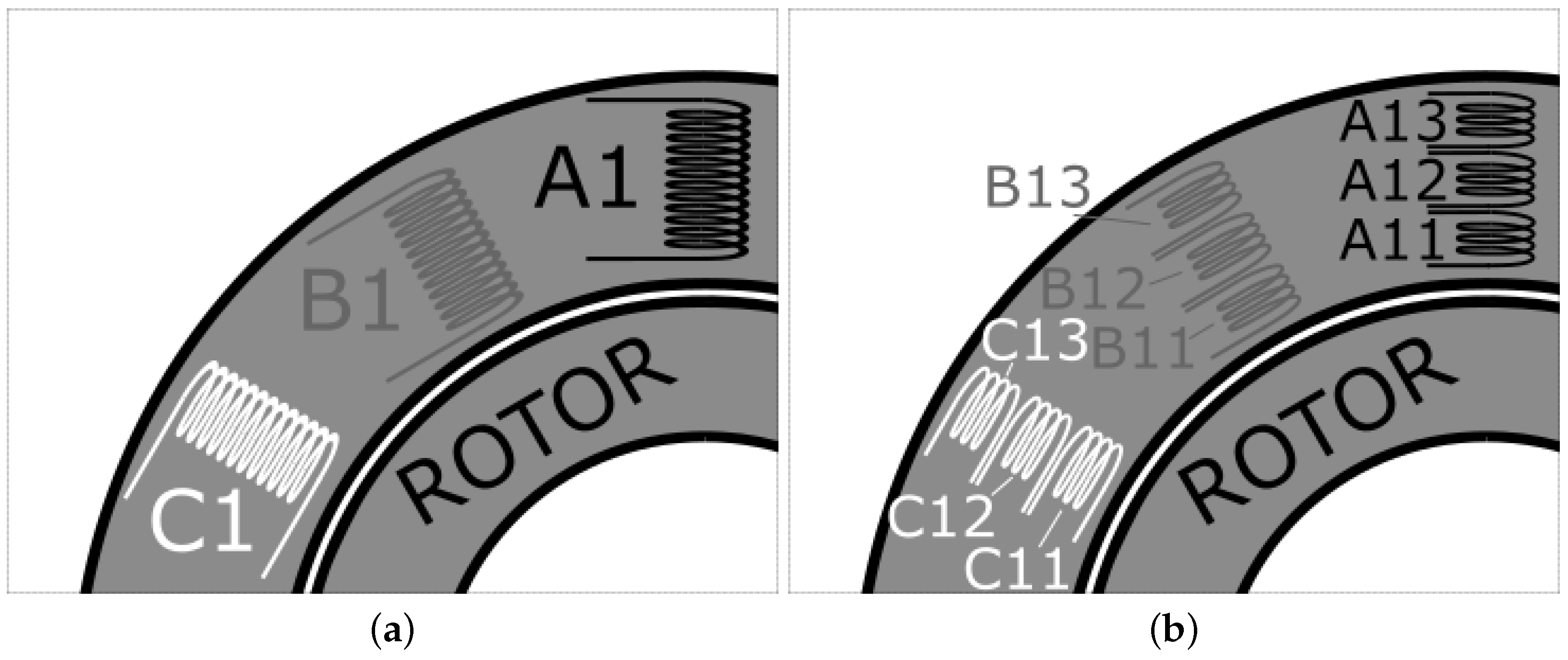
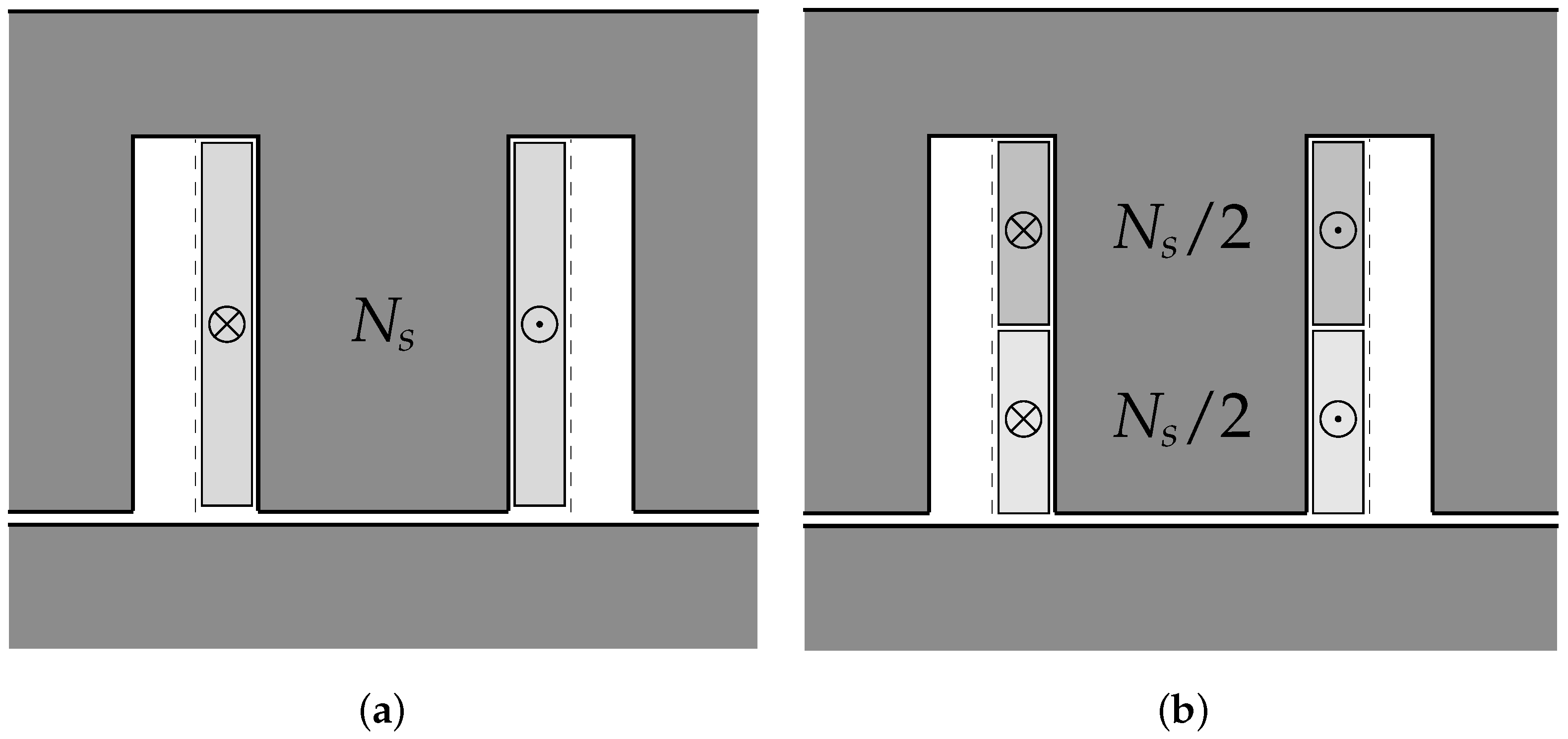
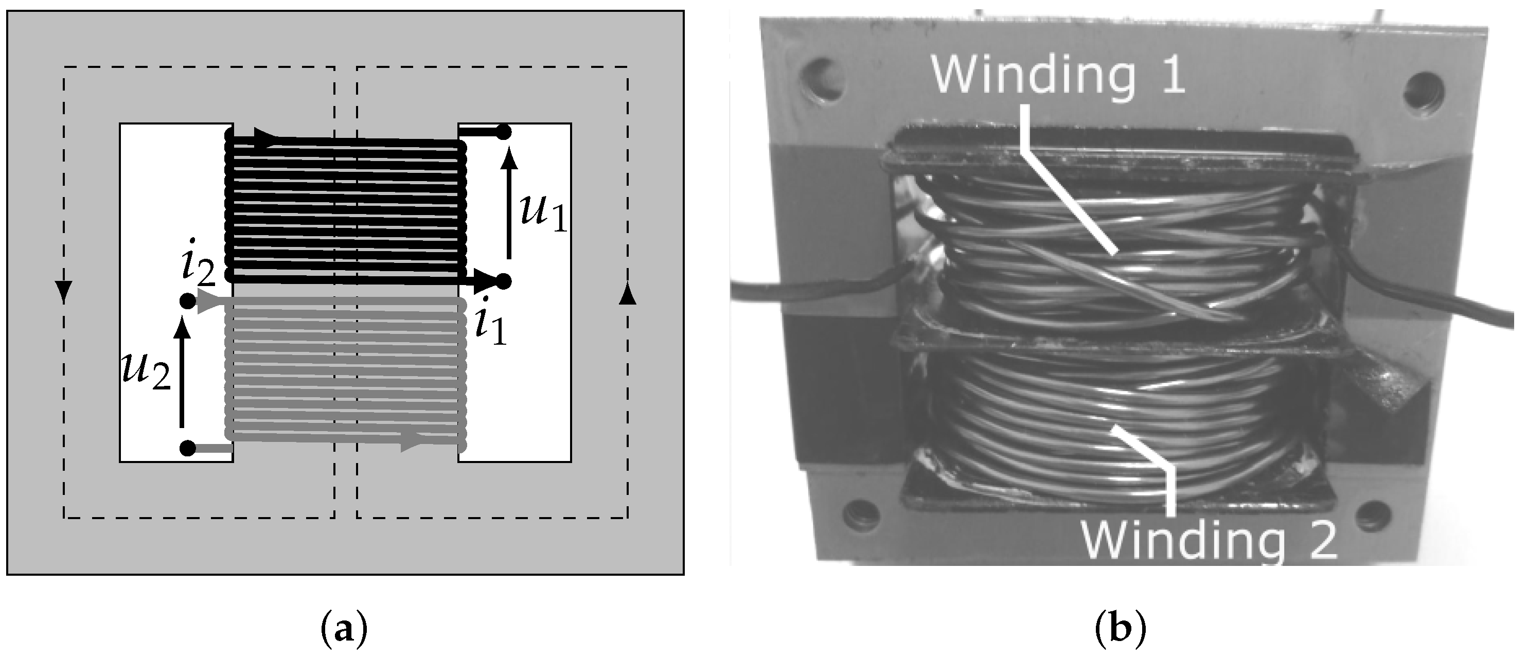
2.1. Defaults in Winding Subdivision Use
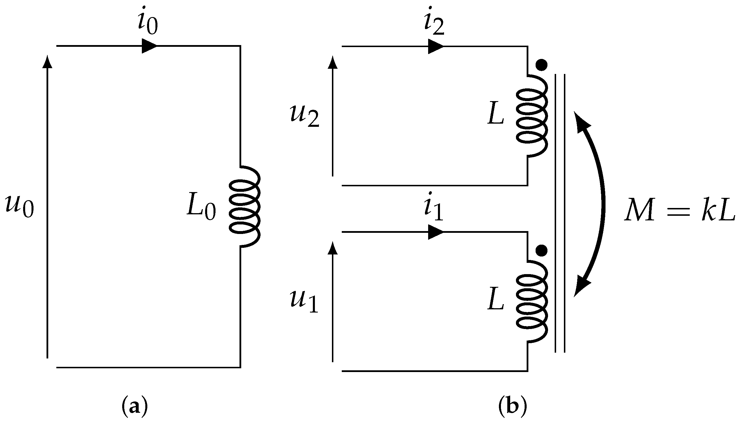
Two windings from the same phase located in one common stator tooth are considered. They result in subdividing a winding of an ordinary electrical machine in two windings with the same number of turns (Figure 3). The airgap influence on electrical disparities between both windings is not considered in this initial study. The aim of this section is to assess the impact of the winding subdivision concept on the winding current ripple using standard PWM voltages. As the studied innovative concept consists in splitting a standard winding into several sub-windings, the adopted performance criterion is named the Current Ripple Ratio C R R , and defined as:
C R R = Δ i Δ i 0
where Δ i is the current ripple in the subdivided case (Figure 4b) and Δ i 0 is the current ripple in a classical architecture (Figure 4a). In order to compare ordinary and subdivided topologies, the magnetic core and the fundamental PWM frequency F s = 1 / T s are fixed. The comparison is made during a single switching period. The winding are supposed to be in a no-load motor configuration as this is the worst case in terms of current ripple, as the magnitude of voltages applied to windings are not decreased by the electromotive force. The magnetic circuit polarisation due to the low-frequency current component is not taken into account because its impact on current ripple is similar in both topologies. The purpose of the study is precisely to understand how the new windings supply impacts the current waveforms and to assess the relative shapes.
To compute an analytical expression of the Current Ripple Ratio C R R , this section considers a basic purely inductive model of the subdivided windings. This kind of inductive model is widely used in the study of interleaved converters [22]. In the present case, the mutual parameter is positive unlike in the multicell converter one. In order to separate the effects related to disparities between the two sub-coils voltages from those related to electrical discrepancies between both subdivided windings, a symmetrical model is considered ( L L 1 L 2 ). Coupled circuit described in Figure 4b leads to:
u 1 u 2 = L k L k L L · d d t i 1 i 2
where k is the coupling factor between two windings. This system relates voltages to current slope as:
d d t i 1 i 2 = 1 ( 1 k 2 ) L · 1 k k 1 · u 1 u 2
This model suggests the relationship between a classical winding configuration (Figure 4a) and a fractioned combination (Figure 4b) excited by two identical voltages ( u 1 = u 2 ):
u 0 = L 0 · d i 0 d t a n d ( u 1 + u 2 ) = L ( 1 + k ) · d ( i 1 + i 2 ) d t
From power electronics point of view, u 0 = ( u 1 + u 2 ) because a subdivided winding requires half initial voltage (Figure 2) and from machiner point of view, Ampere-turns are kept constant using i 1 = i 2 = i 0 as total number of coil turns remains constant (Figure 3). Applied to (4), this leads to
L 0 = 2 · L · ( 1 + k )
This relation is used to evaluate C R R due to differences between the sub-windings voltages compared to ordinary winding case. Models are equivalent when u 1 = u 2 = V D C and u 0 = 2 · V D C . Resulting current shapes are shown in Figure 5a. V D C is the DC-link voltage associated to inverters supplying sub-windings. DC-link voltage associated to an ordinary winding is twice this value as shown in Figure 2. In identical voltage case, (Figure 5a), Δ i current ripple in each subdivided winding is equal to Δ i 0 , which is:
Δ i 0 = 2 V D C L 0 · T s 2 = V D C T s 2 · L ( 1 + k )
Considering that both sub-windings are supplied by their own independent inverters as shown in Figure 2b, u 1 and u 2 may present a time delay or a duty-cycle difference in normal operation mode. Indeed, the propagation time in the switch drivers may slightly differ and similarly the sub-windings discrepancies may induce a little duty-cycle difference to substantially equalise both average currents. These two different aspects are investigated through a basic inductive model represented in Figure 4b. In both cases, namely time delay and duty-cycle difference, the current ripple is computed in order to evaluate C R R induced by the independent control of the sub-windings.

2.2. Delay

This part details the C R R expression while the single voltages face a relative delay which, by definition, does not occur in the standard case (Figure 4a). Two centred PWM characterised by a similar duty cycle are considered: the study is limited to the worst case consisting in α 1 = α 2 = 0.5 . Considering the fact that the propagation time in each driver may present disparities, a time delay τ between the sub-windings voltages may appear as depicted in Figure 5b. When such a delay occurs, four time domains { D 1 , D 2 , D 3 , D 4 } may be distinguished during one switching period. For each domain, the related current slope is computed with (3) and their values are summarised in Table 1.
Following these current evolutions, i 1 and i 2 shapes are shown in Figure 5b. Obvisouly both windings face an additional current ripple when a time delay occurs. Differential mode u 1 = u 2 induced during D 1 and D 3 leads to a high current slope in both windings. Consequently, current shapes are modified compared to the standard synchronised case (Figure 5a); i 2 is in phase opposition with u 2 while i 1 and u 1 are in phase accordance. It demonstrates a new and adverse power flow from the first to the second winding. This power flow between sub-windings is an unwanted side effect in a motor context as it only causes additional losses in the conductors. In this way, this suggests that the control system has to synchronise the sub-windings voltages in order to avoid any differential mode induced by a time delay. Nevertheless, a residual slight delay may appear which clearly relies on technological aspects. To assess the minimum–maximum acceptable delay range, C R R is computed regarding τ T s dimensionless ratio. Deriving from Figure 5b and Table 1, the current ripple due to a voltage delay is:
Δ i = V D C · ( ( 1 k ) T s + 4 k τ ) 2 L ( 1 k 2 )
Δ i = V D C · T s 2 L ( 1 + k ) + 4 k τ 2 L ( 1 k 2 )
Obviously, the minimum value of Δ i corresponds to the standard case Δ i 0 (6). Therefore, it derives:
Δ i = Δ i 0 + V D C 2 L ( 1 + k ) · 4 k τ ( 1 k )
Finally, C R R due to the time delay between subdivided voltages is expressed as:
C R R = Δ i Δ i 0 = 1 + 4 k ( 1 k ) · τ T s
Equation (10) establishes a mathematical relationship between relative delay and current ripple rise based on a single parameter, namely k the coupling factor between both sub-coils. Equation (10) shows that, in switching frequency range, having a low coupling factor lowers current ripple rise. This limits the impact of the voltages delay on C R R . Conversely, at low range frequencies the sub-coils leakage inductances are expected to be small in order to produce a large magnetic field in the air-gap leading to a coupling factor close to 1 (at this frequency range, i.e., from 0 Hz to hundreds of Hz).
Section 4 shows that the coupling factor of two adjacent sub-coils is roughly 0.9 at frequencies around 25 kHz in the studied proof of concept instance. Supposing winding subdivision concept is regarded as acceptable for a current ripple rise lower than 10% (i.e., C R R = 1.1 ), sub-coils voltages should not present a delay higher than τ = 110 ns. It is highly reasonable to consider that power switches drivers propagation time discrepancies are lower than 50 ns. Hence, present technology clearly guarantees a time delay of less than 110 ns. Therefore, residual technological delay appearing between voltages is not a problem in the validation of winding subdivision concept.

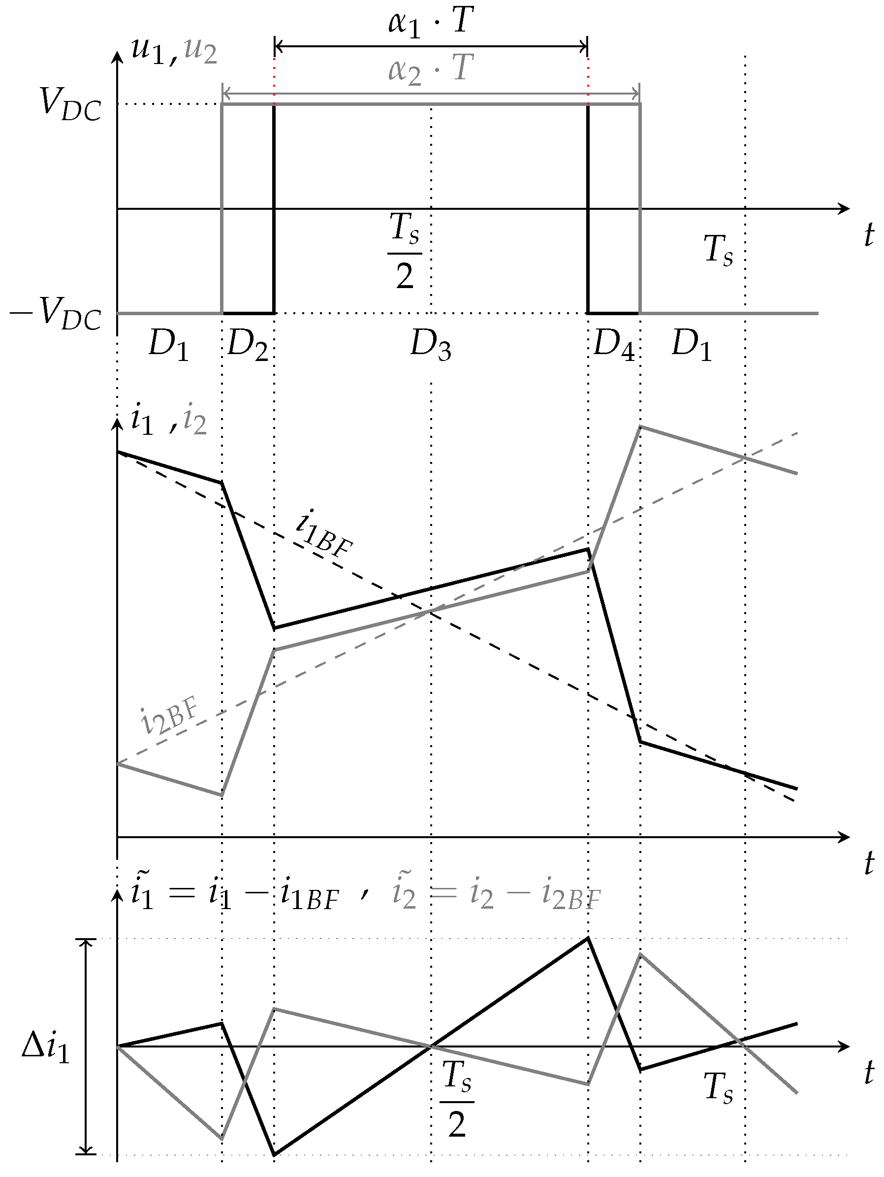
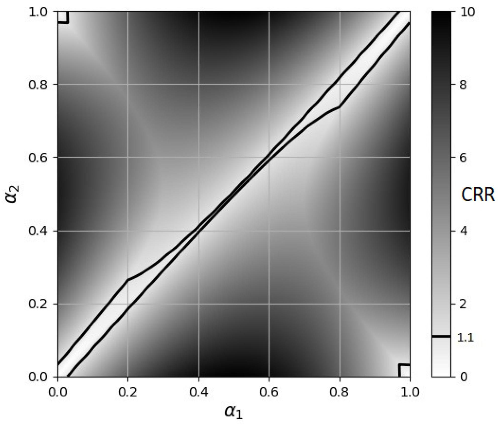
2.3. Duty-Cycle Difference

As current slaving in both coils may be different because of their electrical parameters disparities, it is now assumed that the duty-cycles applied to each converter may differ. Similarly to delay study, duty-cycles difference doesn’t occur in the standard case (Figure 4a). Purely inductive model also enables to investigate the impacts of duty-cycles difference on C R R (1) while supposing τ = 0 . Sub-coils voltages are depicted in Figure 6. In this case, four time domains { D 1 , D 2 , D 3 , D 4 } appear during one switching period. For each domain, the related current slope is computed using (3) and shown in Table 2.
This leads to i 1 and i 2 waveforms represented in Figure 6. Based on the purely inductive model, voltages may present non-zero average values causing sub-coils currents to diverge. As this section focuses on current ripple, low frequency current evolutions (11) are suppressed to exclusively capture high-frequency current component i 1 ˜ and i 2 ˜ . Technically, low frequency current component converges to a permanent value of current related to windings resistance and high-frequency component corresponds to steady state behaviour. This is experimentally verified in Section 2.3.
Using (3) and knowing that average voltages are u 1 B F = V D C · ( 2 α 1 1 ) and u 2 B F = V D C · ( 2 α 2 1 ) , low frequency currents waveforms can be derived as:
d i 1 B F d t = V D C ( 1 k 2 ) L · 2 ( α 1 k α 2 ) ( 1 k ) d i 2 B F d t = V D C ( 1 k 2 ) L · 2 ( α 2 k α 1 ) ( 1 k )
Subtracting the low frequency component (11) to the global current estimated from inductive model (Table 2) leads to extract high-frequency current ripple during each time domain { D 1 , D 2 , D 3 , D 4 } (12). As both windings are considered symmetrical, the current ripple is simply computed in the first winding. In α 1 < α 2 case specific phases D 1 and D 3 last ( 1 α 2 ) T s and α 1 T s , respectively. The related current ripple can be written as:
Δ i 1 D 1 = d i 1 d t d i 1 B F d t D 1 · ( 1 α 2 ) T s = 2 V D C L ( 1 + k ) · α 1 k α 2 1 k · ( 1 α 2 ) T s Δ i 1 D 3 = d i 1 d t d i 1 B F d t D 3 · α 1 T s = 2 V D C L ( 1 + k ) · 1 α 1 k α 2 1 k · α 1 T s
with f k ( α 1 , α 2 ) = α 1 k α 2 1 k et Δ i 0 = V D C T s 2 · L ( 1 + k )
Δ i 1 D 1 = Δ i 0 · f k ( α 1 , α 2 ) · 4 ( 1 α 2 ) Δ i 1 D 3 = Δ i 0 · 1 f k ( α 1 , α 2 ) · 4 α 1
Δ i 1 = m a x Δ i 1 | D 1 , Δ i 1 | D 3
Finally, in the α 1 < α 2 case, CRR in first winding is computed as
C R R = Δ i 1 Δ i 0 = m a x | f k ( α 1 , α 2 ) | · 4 ( 1 α 2 ) | 1 f k ( α 1 , α 2 ) | · 4 α 1
and when α 1 > α 2 , with
C R R = Δ i 1 Δ i 0 = m a x | f k ( α 1 , α 2 ) | · 4 ( 1 α 1 ) | 1 f k ( α 1 , α 2 ) | · 4 α 2
CRR in the first winding is easily calculated for any combination of duty-cycles and the results are shown as a color map in Figure 7 for k = 0.9 . Black dotted line shows a current ripple increase of +10%. The closer this line is from diagonal α 1 = α 2 the more the structure is constrained in terms of duty-cycle differences. Harsh constrains appear around α 1 = 0.50 (Figure 7). Current ripple rise is higher than 10% if duty-cycle difference reaches 0.005. The current controls have to manage to limit the duty-cycles difference between each inverter below this critical value. Ensuring that the duty-cycles difference remains below 0.005 enables to safely exploit the studied architecture degrees of freedom and limit the additional current ripple below the 10% chosen limit. This 0.005 value is consistent with an at least 8-bit duty-cycle quantification. Indeed, duty-cycle differences can be used to equalise both low-frequency currents components without inducing more than a 10% rise of high-frequency current ripple. Purely inductive model gives a pertinent estimation of delay and duty-cycle consequences. It also provides an analytical expression of the current ripple rise induced by winding subdivision concept. Technological delay does not induce more than 10% rise of current ripple. Under the same limit, duty-cycle can be used to balance average currents in subdivided windings as the duty-cycle quantum is under the maximum duty-cycle difference. Nonetheless, this model omits several phenomena, such as parasitic capacitance or losses in conductors and magnetic materials. In order to compute high-frequency losses and improve current estimation, another model has to be considered. As explained in Section 1, finite elements methods require high compute time consumption, therefore, frequency resolution is considered.

3. Current Ripple Estimation from Admittance Measurements

3.1. Current Harmonics Computation

In previous section, the basic inductive model represented in Figure 4b is employed through (3) in previous section but it can also be represented in a spectral way through its admittance matrix:
Y ̲ = 1 j ( 1 k 2 ) L ω k j ( 1 k 2 ) L ω k j ( 1 k 2 ) L ω 1 j ( 1 k 2 ) L ω
Technically, two autonomous inverters provide a PWM voltage to each subdivided windings. The voltages u 1 and u 2 represented in Figure 5b or Figure 6 are periodic with a switching frequency F s = 25 kHz. Considering each n order harmonic of these voltages U ̲ 1 n and U ̲ 2 n enables to compute a spectral estimation of each n order current harmonic I ^ ̲ 1 n and I ^ ̲ 2 n according to the admittance matrix (17). Indeed, the admittance matrix of the n order pulsation ω n permits to link directly the n order voltage harmonic to the n order current one:
I ^ ̲ 1 n I ^ ̲ 2 n = Y ̲ 11 ( ω n ) Y ̲ 12 ( ω n ) Y ̲ 21 ( ω n ) Y ̲ 22 ( ω n ) · U ̲ 1 n U ̲ 2 n
Finally, the subdivided windings currents can be estimated by adding each harmonic contribution. The admittance matrix in (17) corresponds to purely inductive model. This model neglects the resistive behaviour of conductors at switching frequency range, among other things. Therefore, it has to be supplemented by an electrical characterisation. The aim of the following subsection is to establish this matrix on admittance measurements conducted on a practical device in order to refine knowledge of actual windings electrical behaviour. The inductive model and the one based on the admittance measurements are compared through the same method detailed in (18).

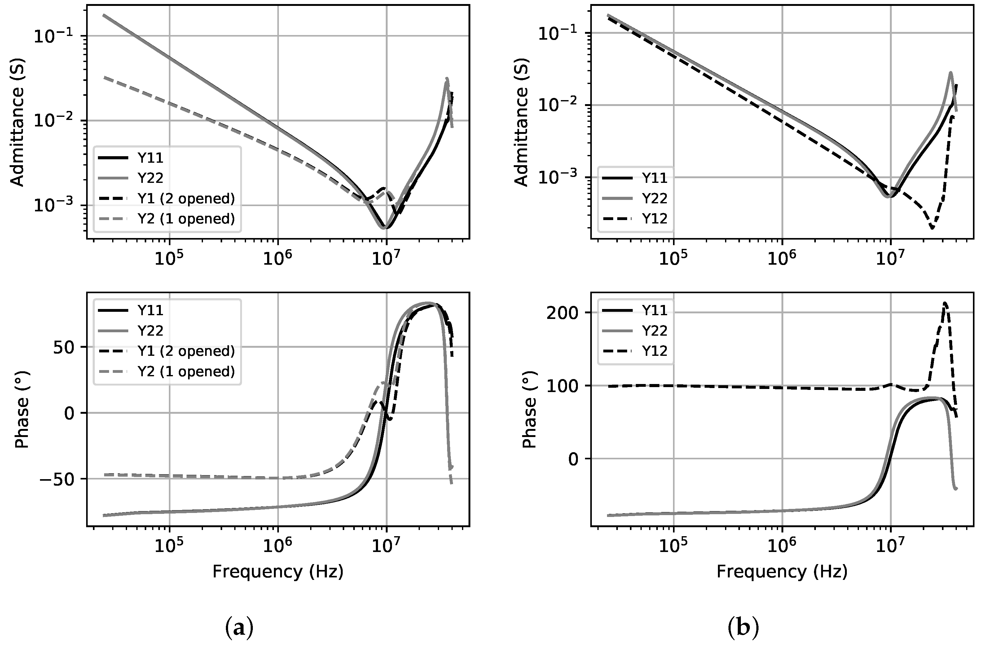
3.2. Admittance Matrix Measurements

In (18), two types of terms have to be detailed. The diagonal terms can be directly measured with a 1-port Impedance Analyser as, for example Y ̲ 11 = I ̲ 1 / U ̲ 1 U 2 = 0 requires current and voltage on the same winding. Nevertheless, trans-admittance terms like Y ̲ 12 = I ̲ 1 / U ̲ 2 U 1 = 0 cannot be provided by this measuring instrument as current and voltage are not measured in the same winding. In this part, possible measures are detailed and then, the derived computation of trans-admittance terms is also explained.
A practical device is built in order to test a proof of concept and validate subdivided windings modelling detailed in Section 2. This device is composed of two 20-turn windings wound around a laminated steel magnetic circuit without airgap as shown in Figure 8a. Lack of airgap moves away from the electric machine context but it provides two windings with similar electrical properties at switching frequency range enabling to exclusively focus on how voltages time delays and duty-cycles differences may impact sub-coils currents ripples. Once the practical device had been created, small signals impedance measurements are carried out using a Keysight E4990A Impedance analyser. These are convenient, harmless and provide information on the device electrical properties over a wide frequency range. For each winding p, while other winding q is opened Y ̲ p i q = 0 = I ̲ p / U ̲ p I q = 0 (dotted lines in Figure 9a) or short-circuited Y ̲ p p = I ̲ p / U ̲ p U q = 0 , 1600 admittance measures are performed from the switching frequency F s = 25 kHz up to 40 MHz corresponding to the one thousand six hundredth harmonic.
Figure 9a shows that both windings are nearly identical for frequency under 5 MHz. Thus, it appears that the symmetry hypothesis is verified for this practical device. Nonetheless, cross-coupling terms cannot be directly measured. Based on the real measurements (Figure 9a), only the product of Y ̲ 12 and Y ̲ 21 can be estimated with any of the following equivalent relations:
Y ̲ 12 · Y ̲ 21 1 = Y ̲ 11 Y ̲ 1 i 2 = 0 · Y ̲ 22 o r Y ̲ 12 · Y ̲ 21 2 = Y ̲ 22 Y ̲ 2 i 1 = 0 · Y ̲ 11
As admittance matrix is symmetrical, it derives
Y ̲ 12 = Y ̲ 21 = ± Y ̲ 12 · Y ̲ 21 1 , 2
Sign of Y ̲ 12 = Y ̲ 21 is chosen with respect to coupling sign convention represented in Figure 4b. Note that direct trans-admittance measurements using Network Analyser and current probe can also be considered as in [23] for non-symmetrical matrices.
Figure 9b shows the admittance matrix terms computated for coupled inductors sharing the same laminated circuit without any airgap as described in Figure 8a. This term contains information about inductance value dispersion on a wide frequency range. A resonance appears on both windings around 10 MHz indicating a parasitic capacitance of sub-coils. As this measurements are used for current ripple estimation and power loss computing, only values corresponding to harmonic of a lower order than 200 (i.e., 5 MHz) are selected in order to guarantee symmetry hypothesis and to simplify the computation. Indeed, main part of losses is due to current harmonic under 1 MHz with an uncertainty of 0.1%.

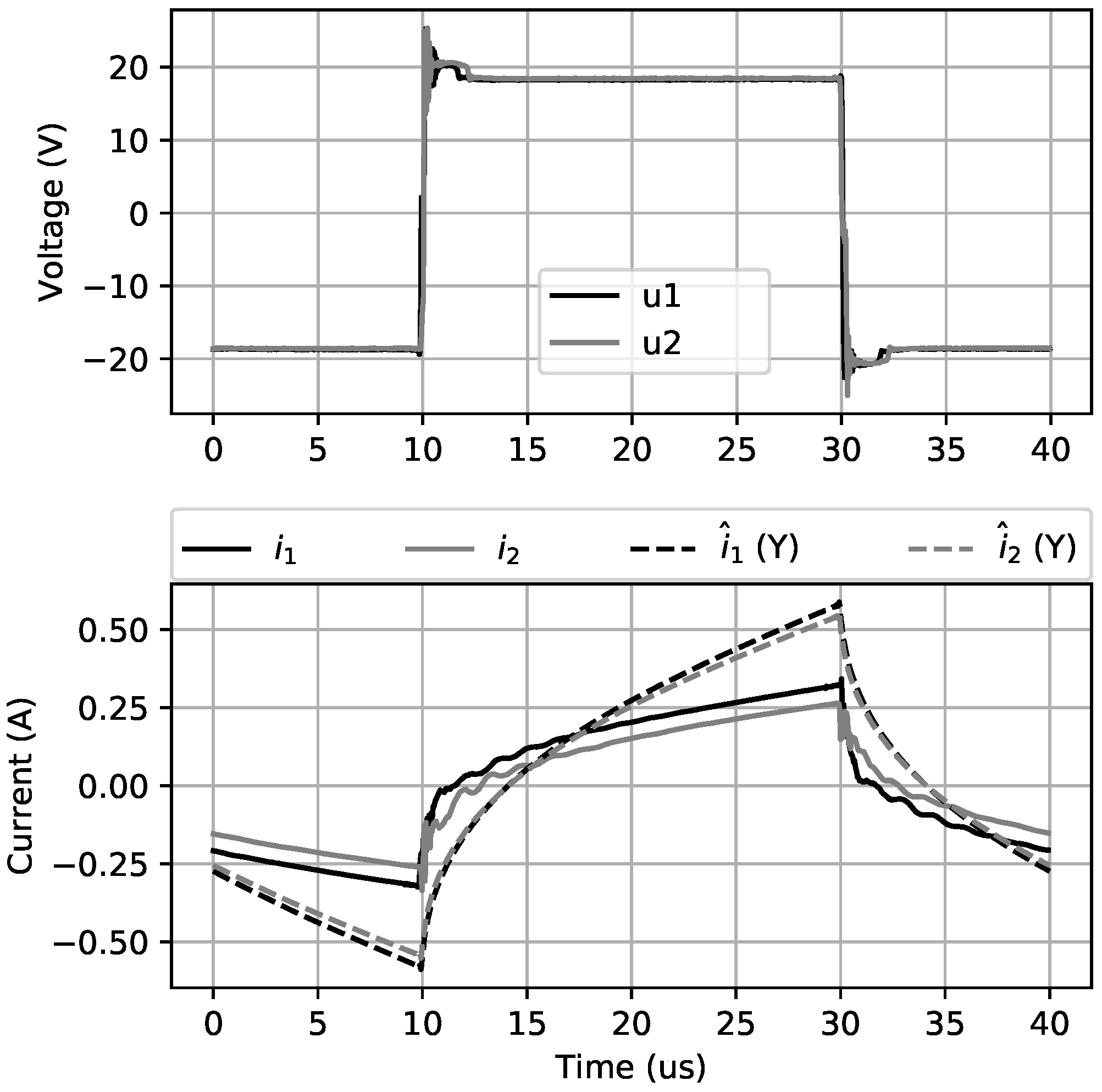
3.3. Comparison of Estimated Current Shape

The measurements presented above are now used to estimate the current ripple during a switching period. The related results are compared with the compared ones provided by the alternative basic inductive model. Figure 10 shows in dashed lines the current shapes obtained with the inductive model described in Figure 4b. The inductive model is based on inductance and coupling factor values measured at switching frequency F s = 25 kHz: L = 190 μ H and k = 0.91 . These current shapes are compared to the estimated ones using all harmonics contribution between 50 kHz to 1 MHz according to (18).
In both current shapes presented in Figure 10a, the chosen delay is not realistic compared to the practical desynchronisation that may occur using modern technologies (i.e., τ = 50 ns). Nevertheless, this delay shows significant impacts on the current ripple and permits to easily compare both models. Specifically, a power flow from the first to the second sub-windings illustrates useless high-frequency additional losses that the proposed architecture must face. It appears through the fact that i 2 is opposed to u 2 whereas u 1 and i 1 are in phase. This experimental result confirms the expected phenomenon presented in Figure 5b using the theoretical inductive model (Section 2.2). Figure 10b validates also currents waveforms predicted by inductive model in case of voltages duty-cycles differences among applied voltages. In both configurations, namely time delay or duty-cycles differences, the estimated current waveform based on admittance model is linear during differential mode, corresponding to u 1 = u 2 , and follows exponential branches during common mode, corresponding to u 1 = u 2 . Because of positive coupling between both sub-windings, the equivalent inductance is low during the differential mode phase leading to fast linear current evolution. On the other hand, during common mode phases, the current evolution is slower and follows exponential branches. In this common mode phases, sub-windings present a higher inductance than differential mode whereas conductor resistance is unchanged.
These comments support the findings described using the basic inductive model while offering more precise information on the actual current waveform. This current ripple estimation based on the admittance measurements also permits to compute extra-losses due to the voltages differences. The estimated losses are then interpreted in the next section through a comparison with measured losses.

4. PWM-Induced Current Ripple: Experimental Validation and Losses Estimation

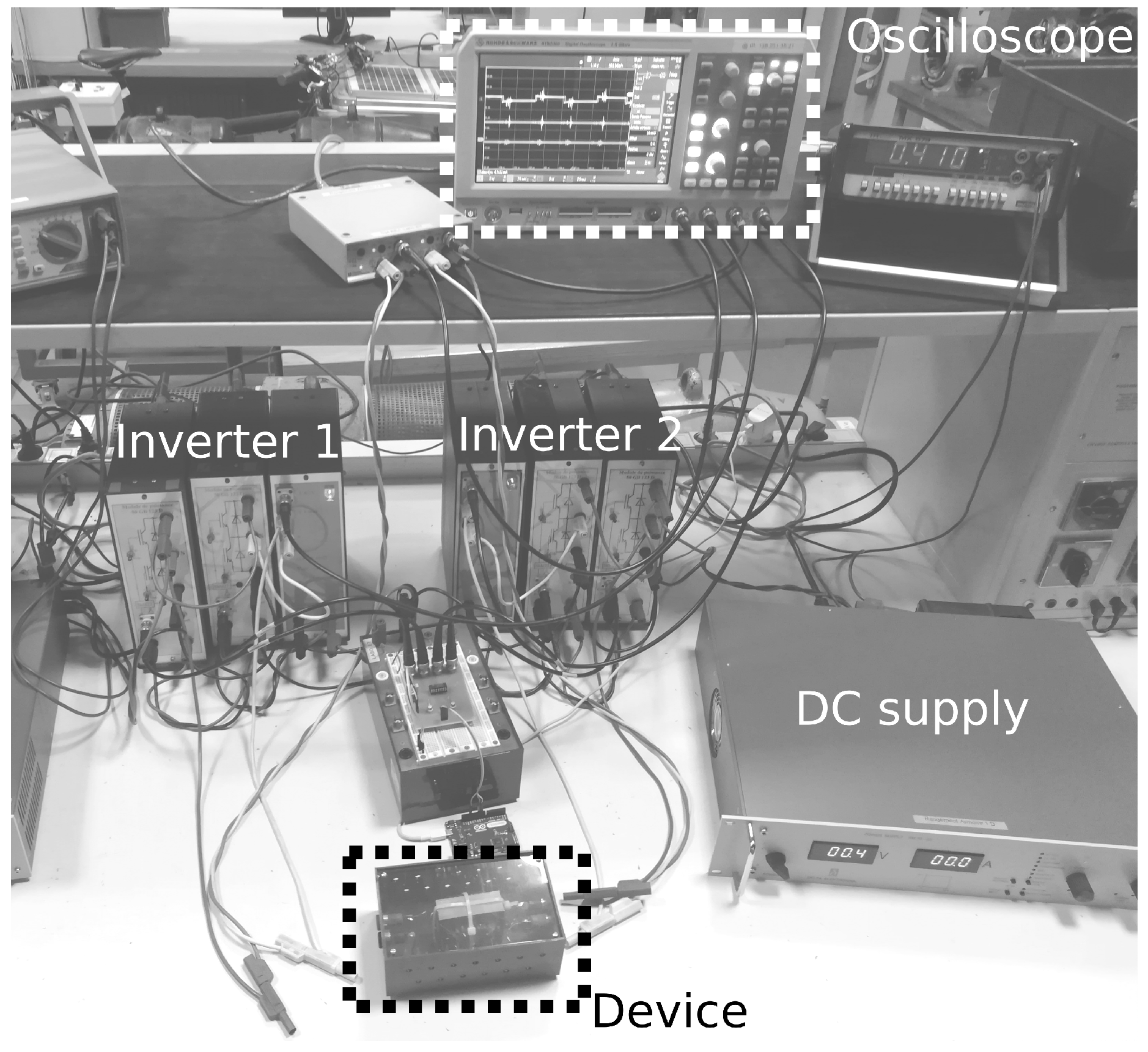
4.1. Experimental Setup

In order to validate the proposed current estimation method, an experimental system is set up. This experimental device (Figure 8b) consists in two four-quadrant fast switching IGBT inverters which independently supply two-coils wound around the same magnetic core. Both inverters are connected to the same DC low voltage bus (Figure 11). An Arduino card provides control signals for both inverters in order to supply the two sub-windings with voltages similar to the theoretical waveforms presented in Figure 5b or Figure 6. The switching frequency is set to 25 kHz and the time resolution of the delay between both control signals is 0.1 μ s. As far as voltages u 1 and u 2 are concerned, the microcontroller enables to control their time delay and their duty-cycles difference. The low DC-link voltage is provided by a stabilised power supply. Its value is chosen considering that, in electric machine context, a 1T induction varying at 500 Hz in the chosen magnetic core would induce a 20 V EMF in the 20-turn sub-windings. Therefore, the power supply regulates DC-link voltage to a 20 V value. Two current sensors measure each sub-winding current. The voltage is also measured at each winding terminal. The four resulting signals are sampled at 20 MHz by an oscilloscope and processed using a Python routine.
First, the inverters feeding both windings are synchronised. Voltages and currents measured on the device under test are shown in Figure 12. The harmonics of the measured voltages are used in (18) to estimate the sub-windings currents which requires a precise knowledge of the admittance matrix. This measured current waveforms have similar shapes than the ones predicted using the frequency model (Section 2) but with lower magnitude. This can be explained by the fact that the admittance measurements are carried out with a impedance meter and hence using low voltage values, namely a voltage magnitude forty times lower than the one generated by the PWM inverters. Non-linearity causes the admittance matrix to depend on the voltage magnitude and must explain observed deviations.

4.2. Delay Study

After having validated the contrast between estimated and measured currents in a synchronised case, time delay effect is investigated. Section 2.2 has shown a transfer from the winding whose voltage is in phase advance with respect to the other. This phenomenon is particularly noticeable in practical experiment since time delays are deliberately set to a much higher than the expected ones (Section 2). A symmetrical configuration represented by the practical device without airgap is tested. In case where u 2 presents a 2 μ s delay with u 1 , has shown in Figure 13a, power flowing from winding 1 to winding 2 is also visible on the magnitude of each voltage. Although, the DC-link voltage is regulated to 20 V, u 2 presents a higher continuous value (21–22 V) whereas u 1 maximum continuous value is slightly lower than 20 V. This imbalance in DC voltage inverters inputs values is a consequence of the described adverse power flow; it is a consequence of the actual unavoidable resistive connections of the DC-bus. The use of a symmetrical model proves that this imbalance is only due to the delay between voltages.
Figure 13a,b show that during the phase where u 1 = u 2 , voltages measured at the winding terminals drops by 5 V compared to the DC-bus voltage because connections impedances are no longer negligible compared to the device impedance. This is so because the coupled inductors have low inductance in differential mode as shown in Table 1. At 25 kHz, the device under test presents a 20 μ H inductance which is almost in same order of magnitude than connections parasitic inductance. This effect tends to minimise the impact of the delay on the current ripple rise compared to the theoretical predictions (1) but it is taken into account in the above estimation.

4.3. Duty-Cycle Discrepancies

Admitting that the control signals are now synchronised, the duty-cycles difference is henceforth investigated. The configuration for which α 2 is higher than α 1 is presented in Figure 13b. The average value of u 2 is positive, so i 2 evolves around a continuous average value of 3 A whereas i 1 is centred around 0 A. The average value of i 2 is suppressed in order to only visualise its current ripple. The estimated and measured currents are depicted in Figure 13b; they show some disparities but current shapes are similar in both differential and common modes. The windings currents average values induce a magnetic circuit polarisation that must change admittance matrix terms. A thermal drift also occurs when continuous average currents are maintained which subsequently also alter these terms. These phenomena are not taken into account in the present study. These aspects introduce some inconsistencies between estimations and measurements.

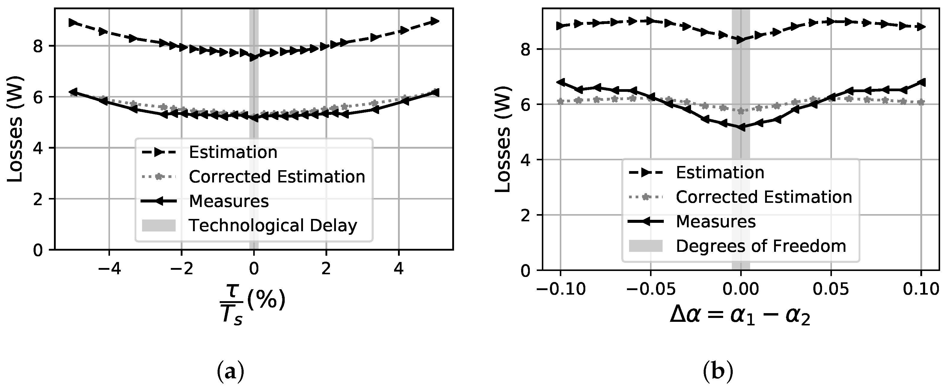
4.4. Losses Estimation

Based on the current and voltage measurements, losses P m e a s u r e occurring within experimental device are calculated as showed in (21).
P m e a s u r e = 1 T s 0 T s ( u 1 ( t ) · i 1 ( t ) + u 2 ( t ) · i 2 ( t ) ) d t
It can be compared to P e s t i m a t i o n (22) resulting by adding up all the individual harmonic losses estimated from the admittance measurements and the spectral decomposition of the measured voltages.
P e s t i m a t i o n = n = 1 U ̲ 1 n · I ^ ̲ 1 n * + U ̲ 2 n · I ^ ̲ 2 n *
where U ̲ p n is the n-order complex voltage harmonic from u p spectral decomposition measured at winding p terminals and I ^ ̲ p n is the n-order complex current harmonic estimation in the sub-coil p.
The losses based on the measured electrical variables are compared with the estimated losses computed by injecting the PWM voltage waveform in the frequency model. The comparative results are shown in Figure 14. In the same way as in Section 3.3, the chosen delay is not realistic compared to the practical desynchronisation that may occur using modern technologies. The expected technological delay is shown as a light grey area in Figure 14a, by using the value calculated in accordance with the methodology lai down in Section 2.2. In the case of duty-cycle differences, the comparison is made for duty-cycle differences values that are higher than the limit fixed in Section 2.3. This limit is represented by a light grey area in Figure 14b and corresponds to the degrees of freedom range that can be used to balance the low-frequency currents in each sub-windings. In any case, the estimated losses are roughly 25% higher than the measured ones. As previously explained, these inconsistencies must be related to non-inclusion of thermal aspect and magnetic circuit polarisation phenomenon in the proposed estimation method. System non-linearity causes low voltage admittance measurements to differ from its actual value. Finally, losses comparison shows that the estimation based on the admittance measurements can be corrected by a proper normalisation. By multiplying admittance magnitude by 0.7, the corrected estimation losses are close to measured losses. With this correction factor, the model based on the admittance measures provides a reliable and effective tool for current ripple estimation and high-frequency power losses assessment in the context of subdivided windings.

5. Discussion

The concept of subdividing stator winding [14] is presented in Section 1. On the basis of this innovative principle, the DC-link voltage can be significantly lowered and the combination of several inverters with their relative sub-windings provides a more even PWM voltage distribution than in the classic single-winding–single-inverter combination. Hence, the new configuration should largely reduce the ageing of machine dielectric insulating materials which are extremely impacted at the coil ends by even distribution of d v / d t in standard architectures. Moreover lower voltages throughout the electric drive enables safer maintenance operations and reduces integration constraints.
In addition to these positive effects, the novel studied architecture offers new degrees of freedom since each sub-winding can now be independently controlled. Considering two sub-coils located in the same stator slot, this degree of freedom has to be carefully managed since, by design, the two adjacent coils are highly magnetically coupled. The present study examines the new requirements for the inverter and its associated control system to ensure that they respect these physical constraints. A high degree of control precision is required, which is particularly difficult to achieve considering a single switching period. All other things being equal, the current study demonstrates that actual technological devices permit to follow the essential requirements and allow to operate the new architecture safely.
Obviously, the studied architecture distributes the global power to several small inverter-sub-coil combinations and consequently leads to consider wide-bandgap techology switches such as GaN transistors. They allow to use higher switching frequencies and generate higher d v / d t . Consequently, regarding these new parameters, the problem should be reconsidered on the basis of the present methodology. Addressing this more general issue will enable to tackle the global optimisation of the studied architecture, that is to determine the three optimal parameters, namely the number of fractionation n, the PWM frequency F s and the power switch technology.
This perspective clearly shows that the reported work is a necessary step to ensure the technological feasibility of this subdivided structure. It provides a good insight into the key parameters driving the magnetic interactions in the subdivided windings at the critical switching frequency range. To support the findings, a proof of concept is designed, implemented and extensively detailed. Some of the system parameters are deliberately fixed. To scale up to a prototype level and address the entire machine drive context, it is necessary to consider all possible parameters, which is the next step.

6. Conclusions

In the case of two subdivided windings, the sub-coil voltage constraints are studied using an inductive model. With respect to this specific sub-coil and sub-inverter combination, the main issue is related to any voltage disparities over a PWM switching period. In this case, the two key parameters are the time offset and the duty-cycle difference between the two sub-coil voltages. Both parameters greatly impact the currents in the sub-windings. Subsequently, the model is used to assess the currents waveforms and to evaluate the related current ripple which is compared to that of a standard winding-inverter topology. A theoretical approach enables to compute the maximum operating range of both parameters in order to analyse the technical viability of the studied structure compared to the classical one. The admissible range of the time delay between both sub-coils voltages is consistent with current technologies used to drive power switches. The permissible duty-cycles difference range is also compatible with the range of variation for balancing the low-frequency currents in the subdivided windings. To further reinforce these theoretical results, the understanding of electrical phenomena in sub-windings is improved through admittance measures providing information on its actual electrical behaviour. The resulting method provides an accurate estimate of the current ripple and also the related power losses. This estimation tool is validated by testing a proof of concept system combining two subdivided coils wound around the same magnetic core and supplied by two independent inverters with a common DC bus. The series of various voltage tests confirms the theoretical findings. In most cases, the proposed method of the current waveform estimation provides a reliable model to represent interaction between sub-windings and will help to give a good insight of the winding subdivision concept. However the symmetrical modelling of subdivided windings does not represent properly the effect of the air-gap in the context of an electrical machine. To take the analysis one step further, the ongoing work is to extend the present study to the case of asymmetrical windings.

7. Patents

Author Contributions

Conceptualization, E.L., J.O. and O.B.; methodology, all authors; software, A.C.; validation, all authors; formal analysis, A.C.; resources, J.O.; investigation, A.C.; visualisation, A.C.; writing–original draft preparation, A.C.; writing–review and editing, all authors; supervision, O.B., E.L. and J.O.; project administration, J.O. and O.B.; funding acquisition, O.B. and J.O.

Funding

This research was funded by Ministère de l’Enseignement Supérieur, de la Recherche et de l’Innovation of France. The patent is supported by Centre National de la Recherche Scientifique of France. A research project related to this patent is scientifically and financially supported by both laboratories GeePs and SATIE.

Acknowledgments

The authors would like to thank the members of the technical support team for their help in the realisation of practical models.

Conflicts of Interest

The authors declare no conflict of interest.

References

  1. Cissé, K.M.; Hlioui, S.; Cheng, Y.; Belhadi, M.H. Etat de l’art des topologies de machines électriques utilisées dans les véhicules électriques et hybrides. In Proceedings of the Symposium de Genie Electrique (Sge 2018), Nancy, France, 3–5 July 2018; pp. 3–5. [Google Scholar]
  2. Oswald, N.; Anthony, P.; McNeill, N.; Stark, B.H. An experimental investigation of the tradeoff between switching losses and EMI generation with hard-switched All-Si, Si-SiC, and All-SiC device combinations. IEEE Trans. Power Electron. 2014, 29, 2393–2407. [Google Scholar] [CrossRef]
  3. Han, D.; Li, S.; Lee, W.; Choi, W.; Sarlioglu, B. Trade-off between switching loss and common mode EMI generation of GaN devices-analysis and solution. In Proceedings of the Conference Proceedings—IEEE Applied Power Electronics Conference and Exposition—APEC, Tampa, FL, USA, 26–30 March 2017; pp. 843–847. [Google Scholar] [CrossRef]
  4. Concari, L.; Barater, D.; Toscani, A.; Concari, C.; Franceschini, G.; Buticchi, G.; Liserre, M.; Zhang, H. Assessment of efficiency and reliability of wide band-gap based H8 inverter in electric vehicle applications. Energies 2019, 12, 1922. [Google Scholar] [CrossRef]
  5. Zoeller, C.; Wolbank, T.M.; Vogelsberger, M.A. Inverter-fed drive stator insulation monitoring based on reflection phenomena stimulated by voltage step excitation. In Proceedings of the ECCE 2016 IEEE Energy Conversion Congress and Exposition, Milwaukee, WI, USA, 18–22 September 2016; pp. 1–8. [Google Scholar] [CrossRef]
  6. Florkowski, M.; Florkowska, B.; Zydron, P. Partial discharges in insulating systems of low voltage electric motors fed by power electronics—Twisted-pair samples evaluation. Energies 2019, 12, 768. [Google Scholar] [CrossRef]
  7. Erdman, J.M.; Kerkman, R.J.; Schlegel, D.W.; Skibinski, G.L. Effect of PWM Inverters on AC Motor Bearing Currents and. IEEE Trans. Ind. Appl. 1996, 32, 250–259. [Google Scholar] [CrossRef]
  8. Wang, J.; Li, Y.; Han, Y. Integrated Modular Motor Drive Design WithGaNPowerFETs. IEEE Trans. Ind. Appl. 2015, 51, 3198–3207. [Google Scholar] [CrossRef]
  9. Gerrits, T.; Wijnands, C.G.E.; Paulides, J.J.H.; Duarte, J.L. Electrical gearbox equivalent by means of dynamic machine operation. In Proceedings of the 2011 14th European Conference on Power Electronics and Applications, Birmingham, UK, 30 August–1 September 2011; pp. 1–10. [Google Scholar]
  10. Hoang, E.; Gaussens, B.; Lecrivain, M.; Gabsi, M. Proposition pour accroître la puissance convertible par un ensemble onduleur de tension—Machine synchrone à commutation de flux à double excitation dans une application motorisation de véhicule hybride ou électrique. In Proceedings of the Symposium de Genie Electrique (Sge”14), Cachan, France, 8–10 July 2014; pp. 8–10. [Google Scholar]
  11. Li, G.; Ojeda, J.; Hoang, E.; Gabsi, M. Double and single layers flux-switching permanent magnet motors: Fault tolerant model for critical applications. In Proceedings of the 2011 International Conference on Electrical Machines and Systems, ICEMS 2011, Beijing, China, 20–23 August 2011. [Google Scholar] [CrossRef]
  12. Li, W.; Cheng, M. Reliability analysis and evaluation for flux-switching permanent magnet machine. IEEE Trans. Ind. Electron. 2019, 66, 1760–1769. [Google Scholar] [CrossRef]
  13. Baumgardt, A.; Bachheibl, F.; Patzak, A.; Gerling, D.; Machine, A.E. 48V Traction: Innovative Drive Topology and Battery. In Proceedings of the 2016 IEEE International Conference on Power Electronics, Drives and Energy Systems (PEDES), Trivandrum, India, 14–17 December 2016. [Google Scholar] [CrossRef]
  14. Hoang, E.; Labouré, E. Electric Machine Powered at Low Voltage and Associated Multicellular Traction Chain. WO2018149996, 23 August 2018. [Google Scholar]
  15. Boxriker, M.; Kolb, J.; Doppelbauer, M. Expanding the operating range of permanent magnet synchronous motors by using the optimum number of phases. In Proceedings of the 2016 18th European Conference on Power Electronics and Applications, EPE 2016 ECCE Europe, Karlsruhe, Germany, 5–9 September 2016; pp. 1–8. [Google Scholar] [CrossRef]
  16. Ojeda, J.; Bouker, H.; Vido, L.; Ahmed, H.B.; Cachan, E.N.S. Comparison of 3-phase and 5-phase high speed synchronous motor for EV/HEV applications. In Proceedings of the 8th IET International Conference on Power Electronics, Machines and Drives (PEMD 2016), Glasgow, UK, 19–21 April 2016. [Google Scholar] [CrossRef]
  17. Wu, B.; Xu, D.; Ji, J.; Zhao, W.; Jiang, Q. Field-Oriented Control and Direct Torque Control for a Five-Phase Fault-Tolerant Flux-Switching Permanent-Magnet Motor. Chin. J. Electr. Eng. 2018, 4, 48–56. [Google Scholar] [CrossRef]
  18. Bojoi, R.; Rubino, S.; Tenconi, A.; Vaschetto, S. Multiphase electrical machines and drives: A viable solution for energy generation and transportation electrification. In Proceedings of the 2016 International Conference and Exposition on Electrical and Power Engineering, EPE 2016, Iasi, Romania, 20–22 October 2016; pp. 632–639. [Google Scholar] [CrossRef]
  19. Gubbala, L.; Von Jouanne, A.; Enjeti, P.; Singh, C.; Toliyat, H. Voltage distribution in the windings of an AC motor subjected to high dV/dt PWM voltages. In Proceedings of the PESC Record—IEEE Annual Power Electronics Specialists Conference, Atlanta, GA, USA, 18–22 June 1995; Volume 1, pp. 579–585. [Google Scholar] [CrossRef]
  20. Ghassemi, M. Accelerated insulation aging due to fast, repetitive voltages: A review identifying challenges and future research needs. IEEE Trans. Dielectr. Electr. Insul. 2019, 26, 1558–1568. [Google Scholar] [CrossRef]
  21. Chang, L.; Jahns, T.M. Prediction and Evaluation of PWM-Induced Current Ripple in IPM Machines Incorporating Slotting, Saturation, and Cross-Coupling Effects. IEEE Trans. Ind. Appl. 2018, 54, 6015–6026. [Google Scholar] [CrossRef]
  22. Tamizi, K.; Béthoux, O.; Labouré, E. An easy to implement and robust design control method dedicated to multi-cell converters using inter cell transformers. Math. Comput. Simul. 2019. [Google Scholar] [CrossRef]
  23. Gustavsen, B. Wide band modeling of power transformers. In Proceedings of the 2004 IEEE Power Engineering Society General Meeting, Denver, CO, USA, 6–10 June 2004; Volume 2, p. 1791. [Google Scholar]
Figure 1. 3-phase, 4 teeth per phase machine fractionation by n = 3 : (a) Ordinary case, (b) Subdivided case.
Energies 12 04418 g001
Figure 2. Phase A supply system subdivision by n = 3 . (a) Ordinary case, (b) Subdivided case.
Energies 12 04418 g002
Figure 3. Subdivision by n = 2 of a winding with N s number of turns around a stator tooth (a) Ordinary case, (b) Subdivided case.
Energies 12 04418 g003
Figure 4. Link between two inductive models (a) Ordinary case, (b) Subdivided case.
Energies 12 04418 g004
Figure 5. Voltage and Current Evolution under (a) synchronised control signals, (b) a delay between control signals.
Energies 12 04418 g005
Figure 6. Voltage and Current evolution under a duty-cycle difference α 1 < α 2 .
Energies 12 04418 g006
Figure 7. Color map of current ripple ratio C R R for different duty-cycle values α 1 and α 2 under k = 0.9 . Black line shows 10% current ripple rise limit.
Energies 12 04418 g007
Figure 8. Symmetrical model with 20-turns windings around magnetic circuit without airgap. (a) Theoretical model, (b) Practical device.
Energies 12 04418 g008
Figure 9. (a) Admittance measurements leading to (b) the terms of admittance matrix for 20-turns windings around magnetic circuit without airgap.
Energies 12 04418 g009
Figure 10. Comparison between purely inductive and admittance (Y) based models, F s = 25 kHz. (a) Delay case, (b) Duty-cycle difference case.
Energies 12 04418 g010
Figure 11. Experimental Setup.
Energies 12 04418 g011
Figure 12. Current and voltage measurements with synchronous control signals. The dotted line shows the estimate current waveforms.
Energies 12 04418 g012
Figure 13. Current and voltage measurements with (a) 2 μ s delayed control signals, (b) α 1 = 0.50 and α 2 = 0.60 .
Energies 12 04418 g013
Figure 14. Estimated, Estimated after correction and Measured Losses under (a) delay and (b) duty-cycle difference.
Energies 12 04418 g014
Table 1. Voltage and current slope under a delay.
D 1 D 2 D 3 D 4
u 1 + V D C + V D C V D C V D C
u 2 V D C + V D C + V D C V D C
d i 1 d t V D C L ( 1 k ) V D C L ( 1 + k ) V D C L ( 1 k ) V D C L ( 1 + k )
d i 2 d t V D C L ( 1 k ) V D C L ( 1 + k ) V D C L ( 1 k ) V D C L ( 1 + k )
Table 2. Voltage and current slope under a duty-cycle difference.
D 1 D 2 D 3 D 4
u 1 V D C V D C + V D C V D C
u 2 V D C + V D C + V D C + V D C
d i 1 d t V D C L ( 1 + k ) V D C L ( 1 k ) V D C L ( 1 + k ) V D C L ( 1 k )
d i 2 d t V D C L ( 1 + k ) V D C L ( 1 k ) V D C L ( 1 + k ) V D C L ( 1 k )

