Article

Design and Performance Comparison of Methanol Production Processes with Carbon Dioxide Utilization

1
Department of Chemical and Materials Engineering, Tamkang University, New Taipei City 25137, Taiwan
2
Department of Chemical Engineering, National Tsing Hua University, Hsinchu 30013, Taiwan
*
Author to whom correspondence should be addressed.
Energies 2019, 12(22), 4322; https://doi.org/10.3390/en12224322
Submission received: 12 October 2019 / Revised: 1 November 2019 / Accepted: 12 November 2019 / Published: 13 November 2019
(This article belongs to the Special Issue Carbon Dioxide (CO2) Utilization)

Abstract

:
Carbon dioxide recycling is one of the possible contributions to CO2 mitigation and provides an opportunity to use a low-cost carbon source. Methanol is a commodity chemical that serves as an important basic chemical and energy feedstock with growing demand. For each of the four types of industrial methanol production processes from natural gas (methane), i.e., steam reforming (SR), autothermal reforming (ATR), combined reforming (CR), and two-step reforming (TSR), CO2 utilization cases of (A) no utilization, (B) as reforming step feedstock, and (C) as methanol synthesis step feedstock were designed based on common industrial operation conditions and analyzed for energy consumption, exergy loss (EXloss), net CO2 reduction (NCR) and internal rate of return (IRR). The utilization of CO2 can reduce energy consumption. The processes with the lowest and the highest EXloss are SR and ATR, respectively. All SR processes give negative NCR. All the B-type processes are positive in NCR except B-SR. The highest NCR is obtained from the B-ATR process with a value of 0.23 kg CO2/kg methanol. All the processes are profitable with positive IRR results and the highest IRR of 41% can be obtained from B-ATR. The utilization of CO2 in the industrial methanol process can realize substantial carbon reduction and is beneficial to process economics.

1. Introduction

To meet the Paris 1.5 °C target, 3.75 gigatons per year of concentrated CO2 will be generated from carbon capture facilities [1]. As CO2 is a stable chemical, the utilization of this CO2 source as a raw material for the chemical industry is a challenging task [2]. There are many articles on the reaction pathways or techno-economic assessment of large-scale technologies for the conversion of CO2 into chemicals and fuels [2,3,4,5]. Some identified chemicals which can be produced from CO2 with existing mature or emerging technologies including urea, methanol, salicylic acid, formaldehyde, formic acid, cyclic carbonates, ethylene carbonates, di-methyl carbonate [5]. Among these chemicals, methanol is the feedstock for the production of formaldehyde, methyl tertiary-butyl ether and acetic acid. Methanol can also be used as a fuel or fuel blend. [6,7]. In addition, the methanol-to-olefins and methanol-to-propylene processes allow for the production of feedstock for consumer plastics. Methanol is a building-block commodity chemical with an annual production of over 100 million tons but the annul utilization of CO2 as its feedstock is only 2 million tons [8]. It is worthwhile to investigate the possibility to increase the use of CO2 for methanol production.
The process technology of methanol synthesis is very mature and can be classified into high-pressure, low-pressure, and liquid-phase technology [9]. Industrial production of methanol mainly uses the steam reforming of methane. A new development of methanol production technology is by direct hydrogenation of CO2 using green hydrogen obtained from renewable energy [10,11] and has been demonstrated in a capacity of 1 ton/day [12]. The technology still needs to overcome the hurdles of high cost of obtaining green hydrogen.
Two fundamental types of methane reforming processes are steam reforming (SR) and autothermal reforming (ATR) [9]. The reactions involved are:
CH 4 + H 2 O CO + 3 H 2         Δ H 298 K o = 206   kJ / mol     ( steam   reforming   reaction )
CH 4 + 1 / 2 O 2 CO + 2 H 2         Δ H 298 K o = 38   kJ / mol     ( partial   oxidation   reaction )
The SR reaction is endothermic and external heat supply is necessary. Thermal balance can be obtained in the ATR reactor via partial oxidation followed by the steam reformation of methane. The former reaction of partial combustion generates exothermic heat, which can be utilized by the endothermic reforming reaction; as such, an energy balance is achieved for the reactor. Two variations of integrating SR and ATR are the two-step reforming (TSR) and combined reforming (CR) [13]. TSR uses a steam reformer followed by an autothermal reformer, i.e., the two reformers are connected in series. On the other hand, in CR configuration, the two reformers are connected in a series-parallel way. Part of the methane feed is added to the steam reformer and the other part is sent directly to the autothermal reformer. The output from the steam reformer is sent to the autothermal reformer for further reaction. On methane reforming, much literature has reported the industrial operation conditions of various reforming processes [6,7,9,14].
The utilization of CO2 in natural gas reforming, by the dry reforming reaction, has been extensively studied.
CH 4 + CO 2 2 CO + 2 H 2         Δ H 298 K o = 247   kJ / mol     ( dry   reforming )
However, the carbonaceous deactivation of the catalyst due to high CO2 concentration is a critical problem [15,16]. The concept of combining steam reforming, dry reforming, and partial oxidation of methane, i.e., tri-reforming, was proposed for the production of syngas with desired H2/CO ratios [17]. The selection of appropriate reforming technologies has been conducted by an optimization study for maximum economic profit with the product H2/CO ratio constraint [18].
The reactions involved in methanol synthesis are [9]:
CO + 2 H 2 CH 3 OH    Δ H 298 K o = 90.7   kJ / mol
CO 2 + 3 H 2 CH 3 OH + H 2 O    Δ H 298 K o = 49.5   kJ / mol
In industrial practice, the syngas feedstock for the methanol process is specified to have a CO2/CO ratio of about 0.5 or lower and an M module value of 2.04–2.06, in order to limit H2O formation and carbon deposition [7]. The M module is defined as M = ( H 2 CO 2 ) / ( CO + CO 2 ) .
On the use of CO2 as a raw material for methanol synthesis, Wiseberg et al. [19] compared the direct methanol production process via the hydrogenation of CO2 and the bi-reforming (steam reforming plus dry reforming) of natural gas process. The study concluded that the direct hydrogenation process is economically viable if the hydrogen price is lower than 1000 USD/t but the bi-reforming process is not feasible. Direct hydrogenation can reduce 87% of emissions from the CO2 source but bi-reforming results in the increase of emissions. For the direct hydrogenation of CO2 process, compared to the conventional methanol process, Pérez-Fortes et al. [20] concluded that there is a net but small potential for CO2 emissions reduction. Luu et al. [21] compared different syngas production configurations, including steam reforming, dry reforming, bi-reforming, and tri-reforming, and concluded the dry reforming scheme with H2 addition configuration significantly outperformed others in CO2 emission intensity and methane reliance. A study reported that the methane uptake and the combined CO2 emissions of the power plant and methanol plant can be reduced by adding high-purity CO2 to the syngas feedstock for the methanol plant [22]. The exergy analysis of a similar integrated process, i.e., steam reforming with CO2 addition to the syngas for gas conditioning, with a steam cycle for energy recovery revealed that the major exergy losses come from the reformer, steam cycle, and methanol synthesis reactor [23]. Zhang et al. [24] focused on the methanol plant using tri-reforming syngas production, optimal reforming conditions in terms of reaction temperature, methane/flue gas ratio and pressure were determined by a simulation study. They concluded the plant is economic.
For the natural gas-based methanol processes, alternative process schemes can be evolved via the employment of (1) various methane reforming, i.e., SR, ATR, CR or TSR, which are applied in industry, and (2) different types of CO2 addition. The alternative processes are depicted in Figure 1. In addition to the major feedstock of methane and the CO2 input, the steam and oxygen inputs are shown. Three types of CO2 addition to the process can be identified. Type A processes use only methane as the carbonaceous feedstock of the plant, in other words, there is no utilization of CO2. Type B processes use CO2 as part of the feedstock of the reforming step. Type C processes add CO2 to condition the syngas fed to the methanol synthesis step. Note that the addition of CO2 to the SR reactor makes it involve not only steam reforming but also dry reforming. However, for easy identification, the process is referred to as B-SR in this paper.
The paper presents the comparison of various industrial natural gas-based methanol processes, each operated with different arrangements of CO2 utilization as feedstock, as shown in Figure 1, in terms of the KPIs (key performance indicators) of energy consumption, exergy loss, CO2 utilization, and economic profit. Adopting industrial common operation conditions and process/product constraints, heat integrated design of each process was determined. Rigorous process simulation results were used for the analysis of KPIs.

2. Process Design

The methanol process steps include feed purification, reforming, syngas compression, methanol synthesis, methanol distillation, and recycle and recovery. In this study, feed purification was not included in the process design and simulation. The process simulation employed Aspen Plus® V10 (Aspen Technology, Inc., Bedford, MA, USA) [25] with the Redlich-Kwong equation of state model for the gaseous processing units and NRTL model for the methanol-water distillation column. On the process simulation, the equilibrium rector model RGibbs was used for both reforming and methanol synthesis reactors; the RadFrac model with a tray efficiency of 0.7 was used for the distillation column.
All the alternative processes were designed for producing 99 wt%, 828,000 t/y methanol based on 8000 h/y operation. The raw materials fed into the processes include CH4, CO2, and O2 gases at 20 bar and 20 °C and saturated steam at 30 bar. The design constraints and the process variables adjusted to meet those constraints are listed in Appendix A for each process and the stream table of a representative process, B-ATR, is given in Appendix B. In this section, the description of four representative alternative processes, including the SR process of Type A (A-SR), the ATR process of Type B (B-ATR), the CR process of Type C (C-CR), and the TSR process of Type C (C-TSR), are presented.

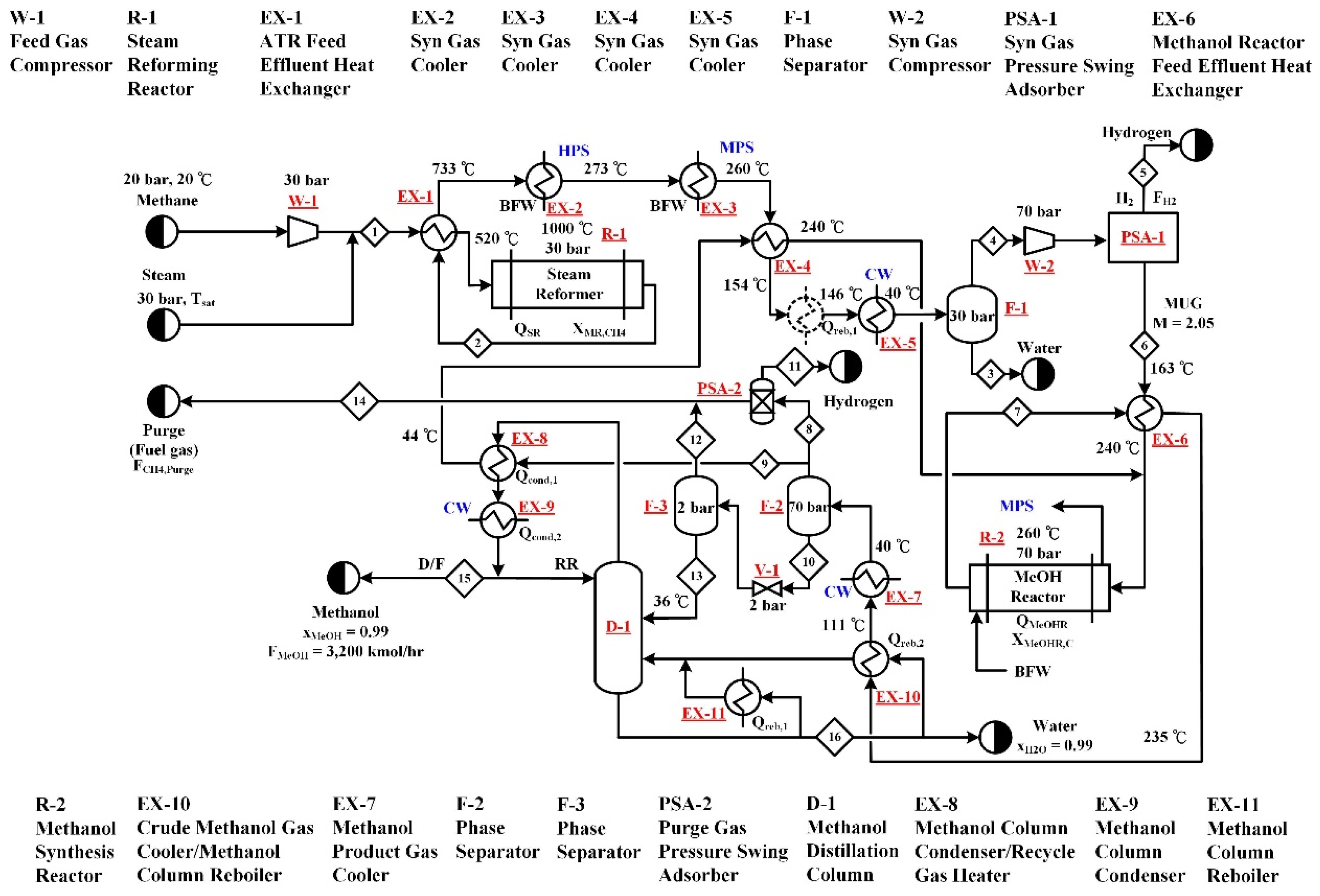
2.1. Type A—Steam Reforming (A-SR) Process

Type A processes are the conventional natural gas-based methanol processes, in which no CO2 is used as feedstock. The process flow diagram of the A-SR process is shown in Figure 2, where the feedstock includes only methane and steam. Based on common industrial operation conditions [6,7,9,14], the pressure and temperature of the steam reformer (R-1) were set to be 30 bar and 1000 °C. The methane and steam feed rates were adjusted to obtain the methanol production rate and the methane conversion specifications. The heat required for isothermal operation of the reactor is provided by natural gas combustion. In this study, the low-pressure methanol synthesis technology using Cu-based catalysts is adopted. The operation pressure and temperature of the methanol synthesis reactor (R-2) were chosen to be 70 bar and 260 °C and the reactor was designed to operate isothermally by releasing the reaction heat to boiler feed water for medium pressure steam generation. The methane feed is first compressed to the reformer pressure followed by being combined with steam and preheated together by the reformer effluent to 520 °C prior to entering the reformer, where 90% of the methane feed is converted. The reactor effluent is recovered for its thermal energy and separated for the water produced from reforming. The syngas is then compressed to serve as the feed gas to R-1. In order to meet the optimal M value of 2.05 of R-2 make-up-gas (MUG), a portion of the hydrogen in the syngas must be removed and a pressure swing adsorption unit (PSA-1) is used for the hydrogen separation. The MUG is then preheated by the methanol reactor effluent and mixed with the recycled unreacted syngas prior to being fed to the methanol reactor. After a series of heat exchanges, a high-pressure phase separator, and a low-pressure phase separator, the methanol reactor effluent is separated into several parts, including the recycle gas sent back to the methanol reactor, the hydrogen byproduct recovered from a PSA unit (PSA-2), a purge gas, and the methanol-water liquid mixture. A distillation column (D-1) is used to separate the liquid mixture into a high purity methanol product and a waste water stream. The heat exchange arrangements depicted in Figure 2 were determined using a pinch design method [26].

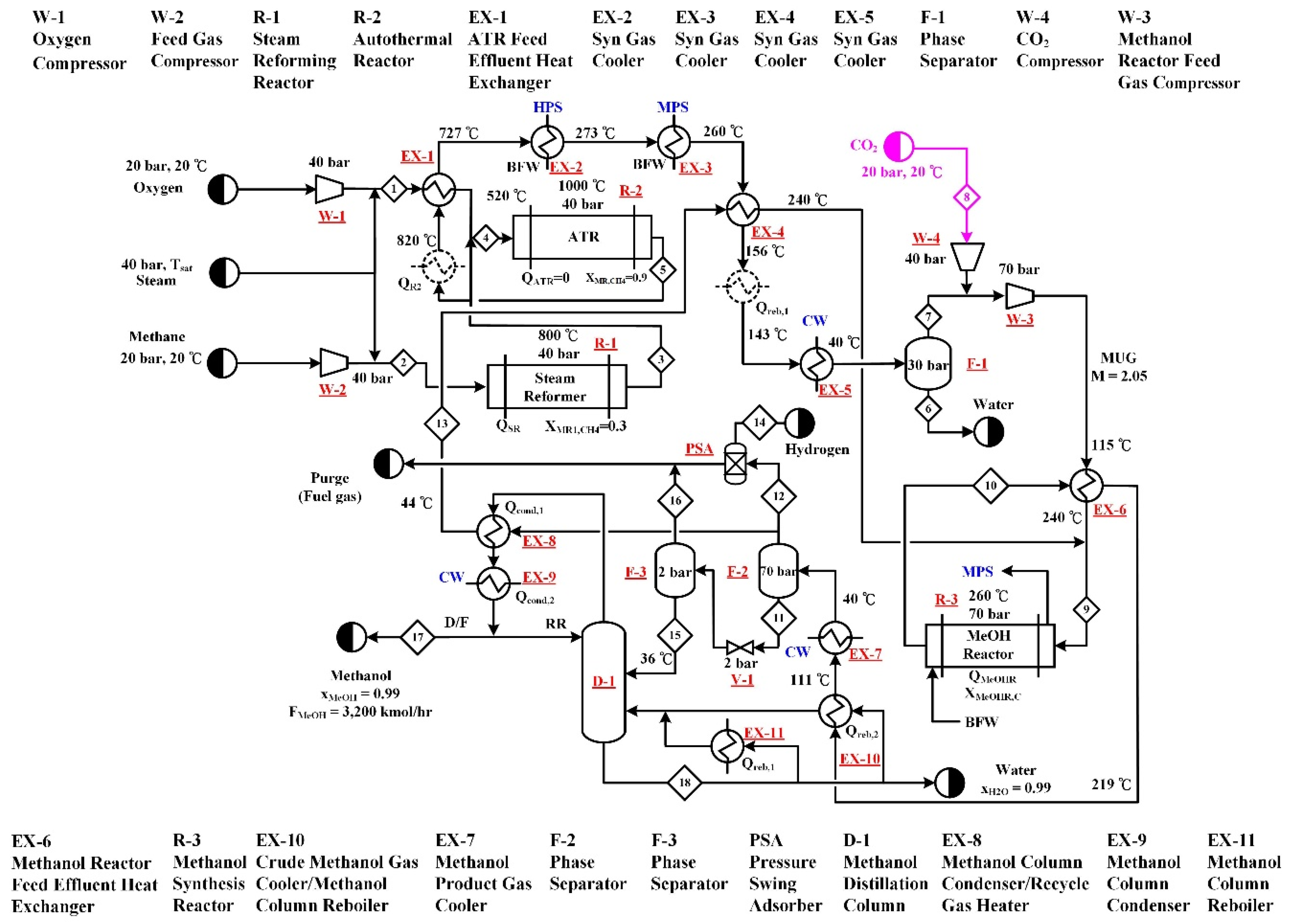
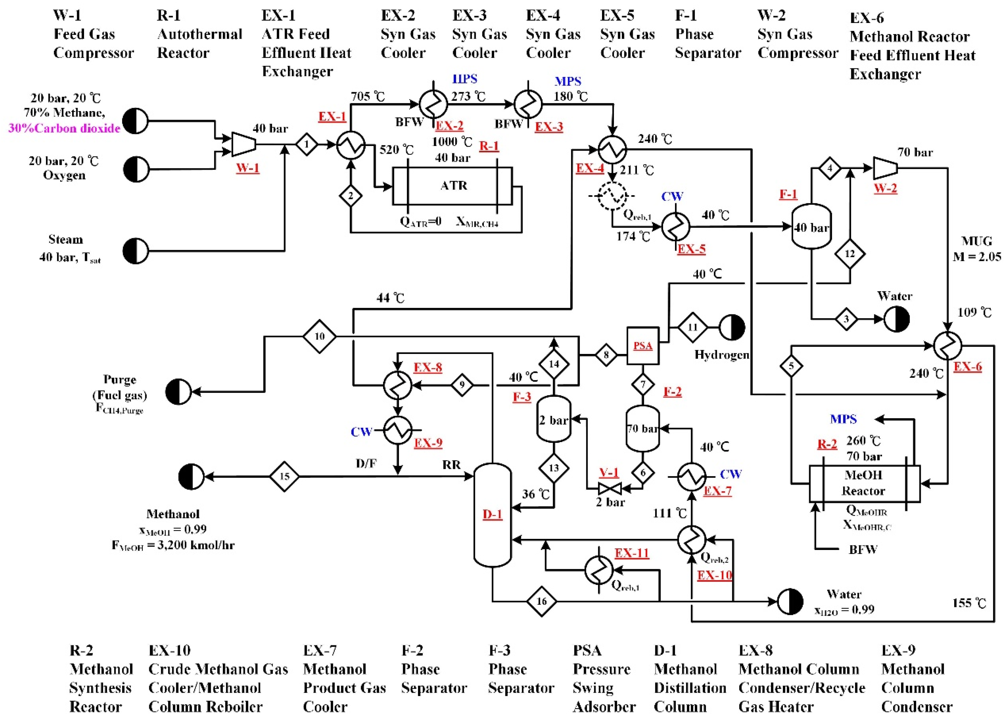
2.2. Type B—Autothermal Reforming (B-ATR) Process

Type B processes utilize CO2 as part of the carbon source for reforming. The process flow diagram of B-ATR process is shown in Figure 3, in addition to the feed stream composed of 70 mol% methane and 30 mol% CO2, the operation of the autothermal reformer requires steam and oxygen inputs. Based on common industrial operation conditions [6,7,9,14], the pressure and temperature of the autothermal reformer (R-1) are set to be 40 bar and 1000 °C. The steam and oxygen feed rates were adjusted to meet the constrains set for the methane conversion and adiabatic operation of ATR. The flowsheet is similar to that of A-SR presented in Section 2.1. Because the H2/CO ratio of the syngas generated from ATR is lower, it is not necessary to purge hydrogen before the syngas is sent to the methanol synthesis reactor (R-2). Hence, there is only one PSA unit, which is located downstream of R-2, in the B-ATR process. The M value of the MUG is controlled by the hydrogen purge rate. The stream table of the B-ATR process obtained from simulation is presented in Appendix B.

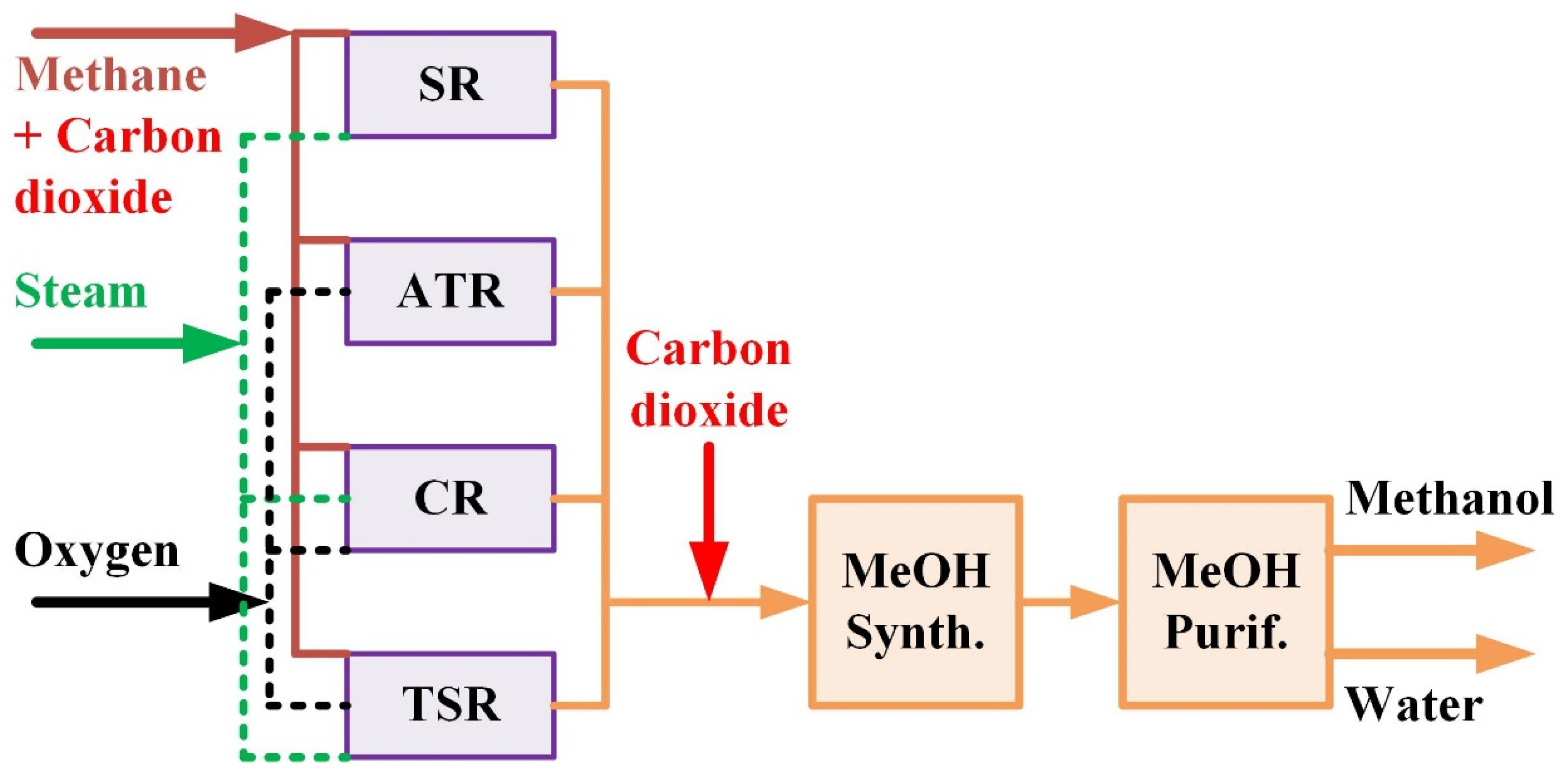
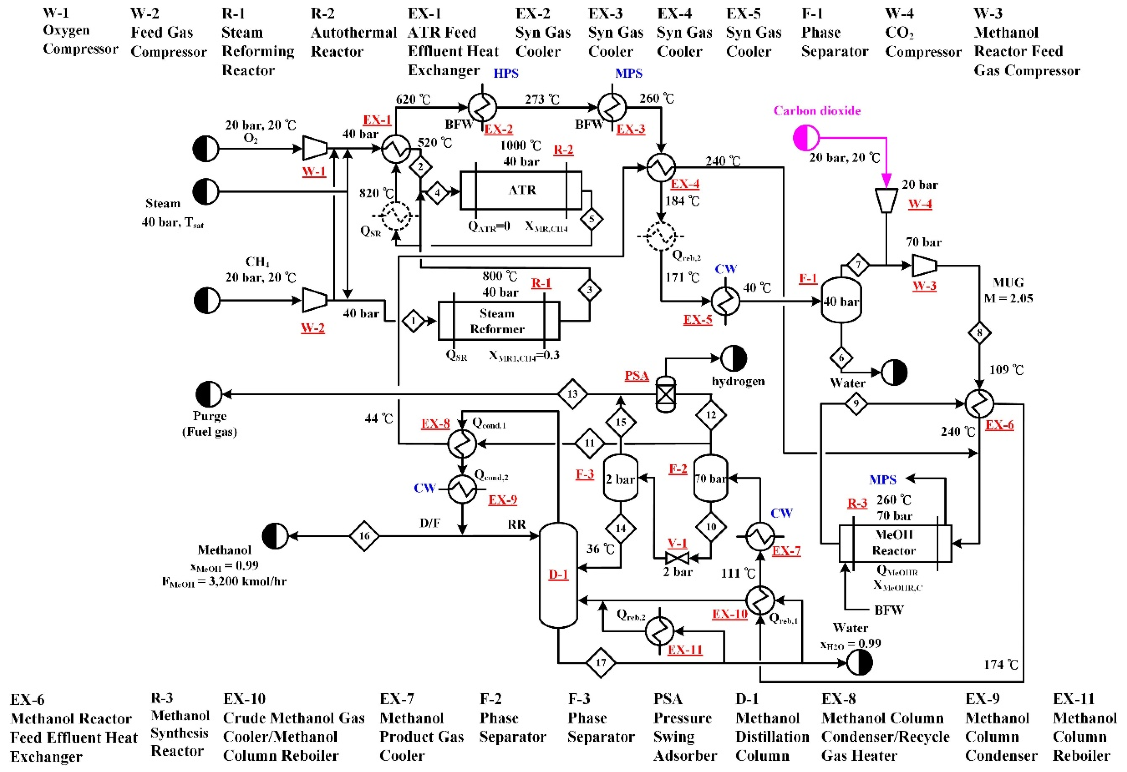
2.3. Type C—Combined Reforming (C-CR) and Two Step Reforming (C-TSR) Processes

Type C processes directly utilize CO2 at the methanol synthesis step. The process flow diagram of C-CR process is shown in Figure 4. The reforming step employs a SR (R-1) and an ATR (R-2) in series-parallel connection, that is the methane and steam are both fed into the SR and ATR, in addition, the product stream leaving the SR is sent to the ATR for further reaction. Hence, the connection is both in parallel and in series. The oxygen feed, which is needed for the ATR, is fed to the ATR only. The operation pressures and temperatures of the SR and the ATR are the same as that described in Section 2.1 and Section 2.2, respectively. The steam feed rates to the two reformers were adjusted to meet their methane conversion targets. The methane and oxygen feed rates were adjusted to meet the constrains of the methanol production rate and adiabatic operation of ATR. Note that an equal amount of methane is fed to the two reformers. Fresh CO2 is combined with the syngas generated from the reforming section to form the MUG sent to the methanol synthesis reactor (R-3). The CO2 feed rate was determined in order to meet the specified M value. The methanol synthesis and product separation section of the process is the same as that presented in Section 2.2. Similar to B-ATR, because the H2/CO ratio of the syngas generated from the CR reforming step is lower, it is not necessary to purge hydrogen before the syngas is sent to R-3. Hence, there is only one PSA unit, which is located downstream of R-3, in the C-CR process.
The process flow diagram of the C-TSR process is shown in Figure 5. The process is the same as C-CR, except that the two reformers, SR and ATR, are connected in series. The SR (R-1) is followed by the ATR (R-2). The total methane feed is fed to the SR, however, fresh steam is fed into both reformers in an appropriate amount to keep the methane conversions of R-1 and R-2 at 0.3 and 0.9, respectively. The part of process following the reforming step is the same as that of the C-CR process.

3. Evaluation and Comparison of Performance Indicators

This section presents the analysis results of the performance indicators, including energy consumption and exergy loss, net carbon dioxide reduction, and cost and economic profit.

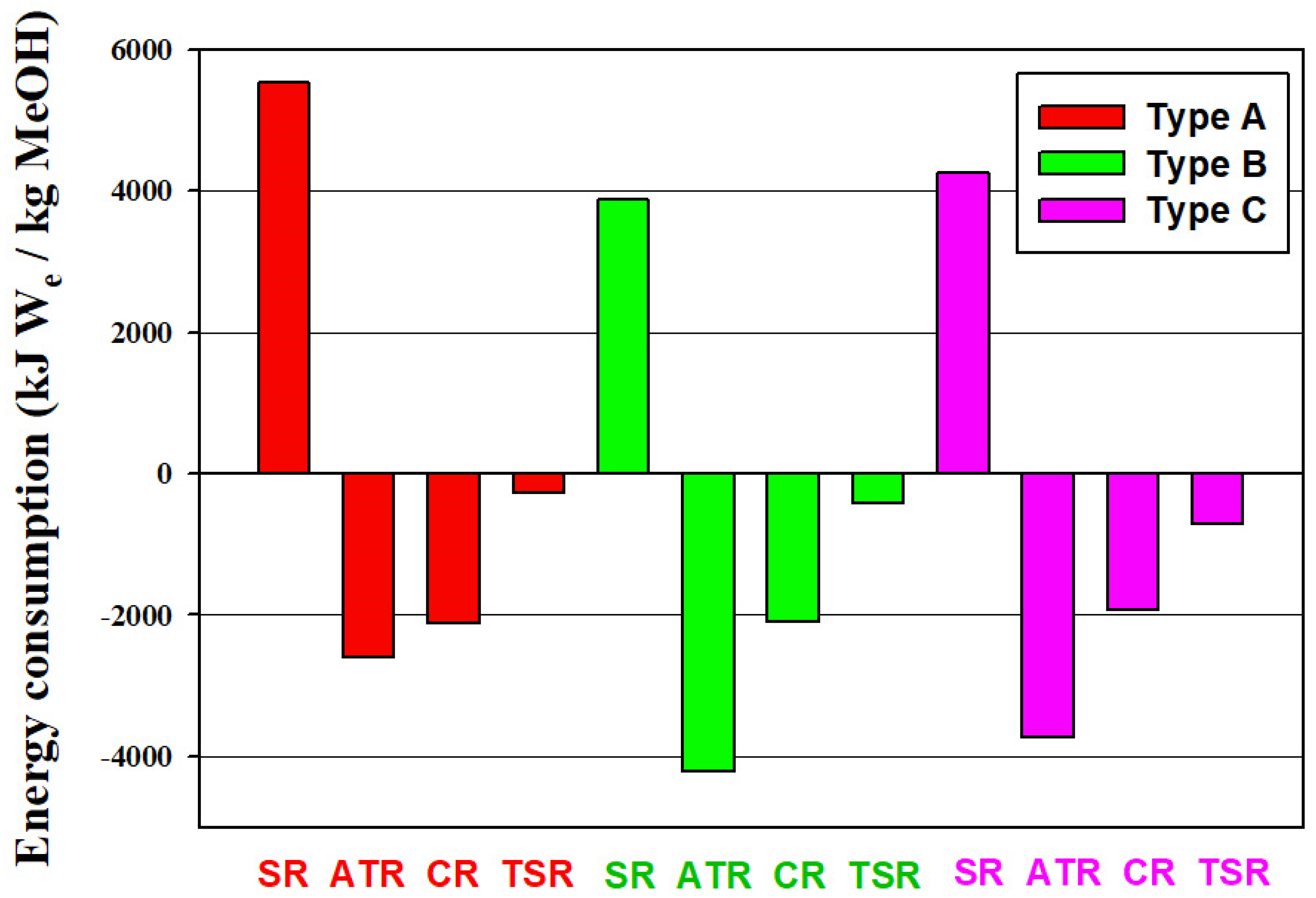
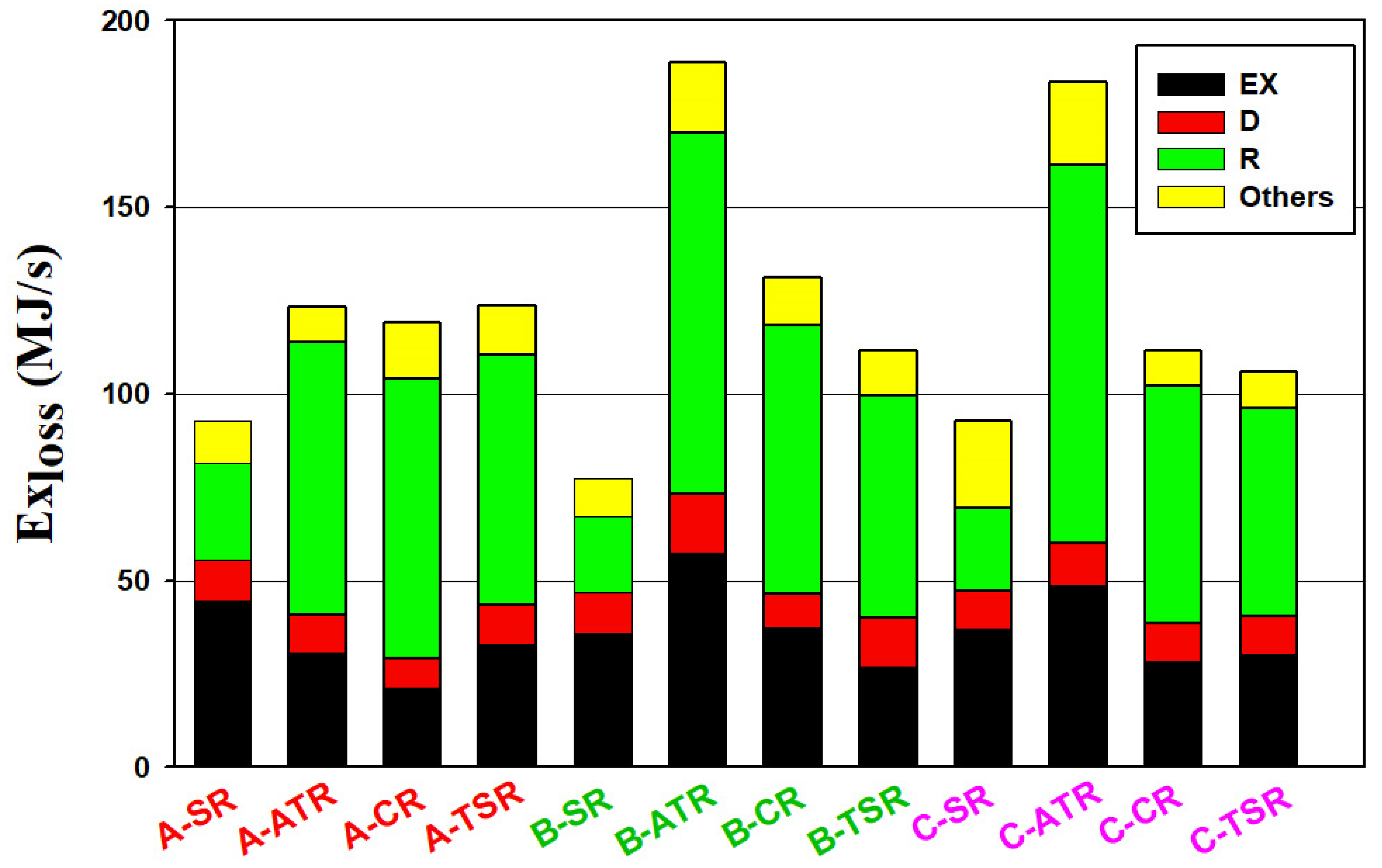
3.1. Energy Use and Exergy Loss

The reforming reactions are endothermic while the methanol synthesis reaction is exothermic. In the reforming part of the process, heat is supplied to the SR reactor by the combustion of natural gas and the ATR reactor is operated adiabatically by partial oxidation of the methane feed. In the methanol synthesis reactor, the reaction heat is recovered to generate medium pressure steam. For each process, heat integration was included in the design. The net energy consumptions of all alternative processes are summarized in Figure 6. In addition to the heat effects of reactors, the energy consumption calculation takes into account the energy requirements of heat exchangers, the power consumption of compressors and the energy recovery from purged fuel gas streams. Note that the hydrogen streams leaving the processes are not considered as energy streams, rather they are accounted for as byproduct streams. Energy consumption is presented as equivalent work (We), that means the thermal energy is converted to equivalent work by the Carnot factor ( 1 T o / T Q ) based on its temperature ( T Q ) and the environmental temperature ( T o ).
All the SR processes require net consumption of energy, while other processes can have net generation of energy because of the adoption of the thermally self-sufficient ATR. Compared to CR and TSR processes, both incorporate SR, more energy can be exported from pure ATR processes. Because the addition of CO2 feedstock reduces the excess hydrogen or the required syngas generation from the reforming step, less energy is exported from B-SR or C-SR than A-SR. Type B and Type C processes have a close net energy consumption.
The exergy balance for each equipment gives the exergy loss of the equipment.
Ex loss = ( H in H out ) T o ( S in S out ) + Q ( 1 T o T Q ) W
The results of exergy loss analysis for all the alternative processes are depicted in Figure 7, including the exergy losses from different types of equipment. For all the processes, the major sources of exergy loss are heat exchangers and reactors. The reason that the SR processes have a higher energy consumption but lower exergy loss is because the exergy loss associated with the natural gas combustion to supply heat to the steam reformer is excluded in the exergy analysis. However, for the processes employing the autothermal reformer, the exergy loss associated with the heat supply via partial oxidation of methane is included in the exergy analysis. These can also explain why the exergy loss of reactors is greater than other equipment for the processes using the autothermal reformer, i.e., ATR, CR, and TSR.
When utilizing CO2 in the reforming step or methanol synthesis step, the combined results of syngas composition and reaction heat effects lead to much higher feed rates required for the ATR reactor, as shown later in Table 1. The exergy losses of B-ATR and C-ATR are hence increased significantly compared to A-ATR. For the CR and TSR processes with CO2 utilization, the combined effects of SR and ATR result in a less significant change of exergy loss compared to the corresponding Type A processes.

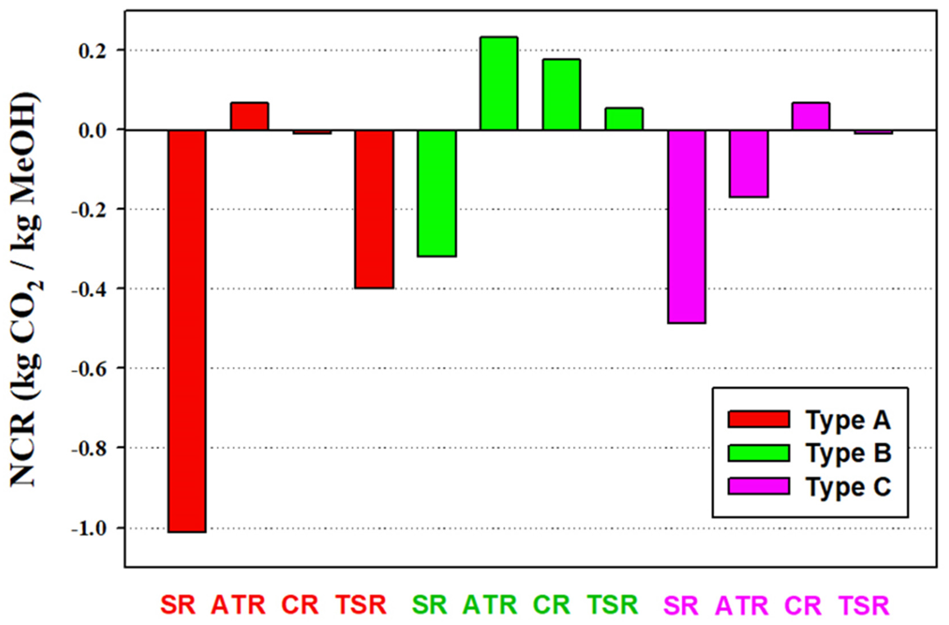
3.2. Carbon Dioxide Utilization

The feedstock flow rates of all alternative processes are listed in Table 1. Except for the SR processes, the CO2 feed rates of Type B processes are much higher than that of Type C processes. This result indicates that the capability of utilizing CO2 is higher in the reforming step than in the methanol synthesis step of the process. The process that uses the highest CO2 feed rate is B-ATR with a CO2/CH4 ratio of 3/7, which is fixed in this study for the Type B processes.
Table 1 also reveals the changes of feed rate of other feedstock relative to the Type A processes. Methane feed rate can be significantly reduced for SR process by utilizing CO2 via Type B or Type C processes. However, for the ATR processes, the utilization of CO2 results in higher methane and oxygen feed rates. For the CR and TSR processes, due to the combination of the SR and ATR configuration, mixed effects on feedstock flow rates are obtained.
Because the energy consumption of each process contributes to CO2 generation and the outlet streams from each process might carry with some CO2, the net carbon dioxide reduction for unit production of methanol (NCR) is determined by:
NCR ( ton   CO 2 / ton   methanol ) = ( CO 2   consumption   CO 2   generation ) / Methanol   production
CO 2   consumption = CO 2 , in CO 2 , out
CO 2   generation = EF ( W Q , in W Q , out + W comp +   W ASU )
where the net consumption of CO2 is determined by the difference between the total inlet flow of CO2 and the total outlet flow of CO2. CO2 generation is calculated using an emission factor, which is the amount of CO2 emission per unit work consumption. A value based on natural gas fueled power generation of 0.15 kg/MJ [27] was adopted. The total work effects taken into account include the equivalent work of total heat input ( W Q , in ), equivalent work of total heat output ( W Q , out ), total compression work ( W comp ), and the work consumption of the air separation unit (ASU) for oxygen feedstock production ( W ASU ). The power required for unit oxygen production is 0.42 kWh/kg [28].
The NCR results are shown in Figure 8. The excess hydrogen generation from the SR processes result in highly negative NCR values, in particular in the A-SR process. The addition of CO2 feedstock, via B-SR or C-SR, can reduce excess hydrogen generation and hence improve the NCR. Type B processes give better performance in terms of NCR than Type A and Type C processes. Except the ATR process, Type C processes have higher NCR than Type A process. Hence, one can make the remark that utilization of CO2 in both the reforming step and methanol synthesis step of the methanol process is beneficial to carbon dioxide reduction. The process with the highest NCR value is B-ATR process with a value of 0.23 kg CO2/kg methanol.

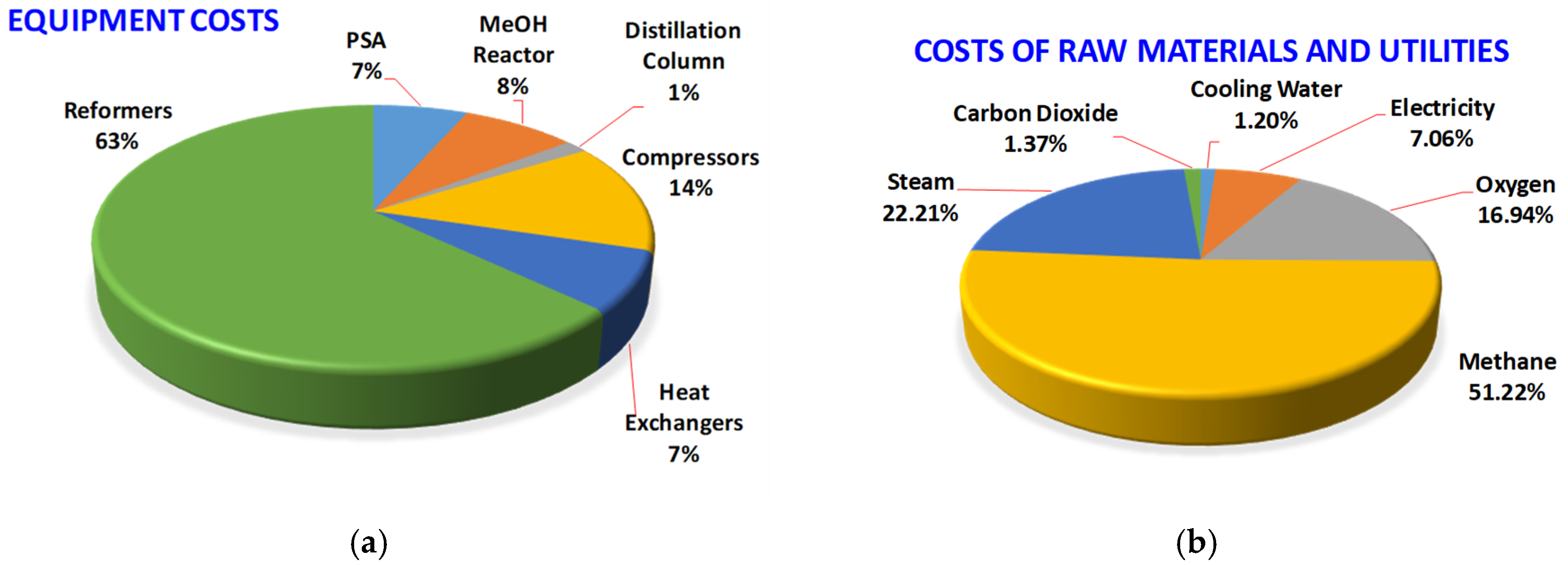
3.3. Cost Analysis and Economic Profit Evaluation

Cost analysis is based on the plant operation of 8000 h/y and the CEPCI of March 2017 [29]. The assumed unit prices of materials, including raw materials, byproducts, product, and utilities are listed in Table 2 based on the information obtained from [28,30,31,32,33,34,35]. For the SR, ATR, and methanol synthesis reactors and the PSA unit, capital investment costs were estimated using data available in the literature which include the scaling factors to account for the equipment capacity [36,37,38,39]. The equipment costs of all other process units were estimated using the correlations provided in [31].
The capital costs and annual manufacturing costs of all alternative processes are shown in Figure 9. The utilization of CO2 in methanol production, i.e., Type B and Type C processes, does not necessarily lead to the increase of capital cost or manufacturing cost. The processes with the highest and the lowest capital cost are B-TSR and B-ATR, respectively. The processes with the highest and the lowest manufacturing cost are A-SR and B-SR, respectively. Use B-ATR as a sample process, the distributions of the equipment cost and the raw material and utility cost are shown in Figure 10. The reformers constitute 63% of the total equipment cost. The costs of compressors and the methanol reactor counts for 14% and 8%, respectively. The costs of the PSA unit and heat exchangers are both 7% of the total equipment cost. With respective to the total operation cost, the proportions of the costs of raw materials, namely methane, steam, oxygen, and CO2 are 51%, 22%, 17%, and 1.37%, respectively. Because only the transportation cost of CO2 is considered, the share of CO2 cost is very small. Because B-ATR is net exporting in energy, as shown in Figure 6, the utility cost involves only the electricity cost and contributes to 7.06% of the total operation cost.
Internal rate of return (IRR) of the alternative processes is analyzed to compare the economic profit. The IRR results, based on the plant life of 20 years and tax rate of 35%, are presented in Figure 11. The same remark as for the Figure 9 can be made. The utilization of CO2 in methanol production, i.e., Type B and Type C processes, does not necessarily lead to a reduction of the profit. For SR processes, the IRRs are B-SR > C-SR > A-SR. For the ATR processes, the IRRs are B-ATR > C-ATR > A-ATR. For the CR processes, the IRRs are A-CR > C-CR > B-CR. For the TSR processes, the IRRs are A-TSR > C-TSR > B-TSR. B-ATR process has the highest IRR with a value of 41%. The lowest IRR process is B-TSR and the value is 12.5%.

4. Conclusions

As methanol is a key building-block commodity chemical and energy feedstock, the utilization of CO2 in the production of methanol is an important research topic. For the industrial low-pressure methanol production process with different synthesis gas generation reactors, i.e., SR, ATR, CR, and TSR, employing two CO2 utilization approaches, i.e., to serve as feedstock to reforming or methanol synthesis, this paper presents a comprehensive and in-depth study. The study accomplishes the process design with energy integration and the performance index analysis, including the energy consumption and exergy loss, net CO2 utilization, and cost and profit.
The results of this study show that:
  • With the utilization of CO2 in the methanol process, the major energy effects are on the SR and ATR processes. Less energy input to the process is needed (SR) or more energy output from the process (ATR) can be obtained.
  • With the utilization of CO2 in the methanol process, the total exergy loss is increased significantly for the ATR processes, in particular from the reactors.
  • The use of CO2 as part of the reforming feedstock (Type B processes) can utilize more CO2 than the direct use of CO2 as the methanol synthesis feedstock (Type C processes). The process uses the highest CO2 feed rate is B-ATR.
  • The utilization of CO2 in both the reforming step and methanol synthesis step of the methanol process is beneficial to the carbon dioxide reduction. The process with the highest NCR value is the B-ATR process with a value of 0.23 kg CO2/kg methanol.
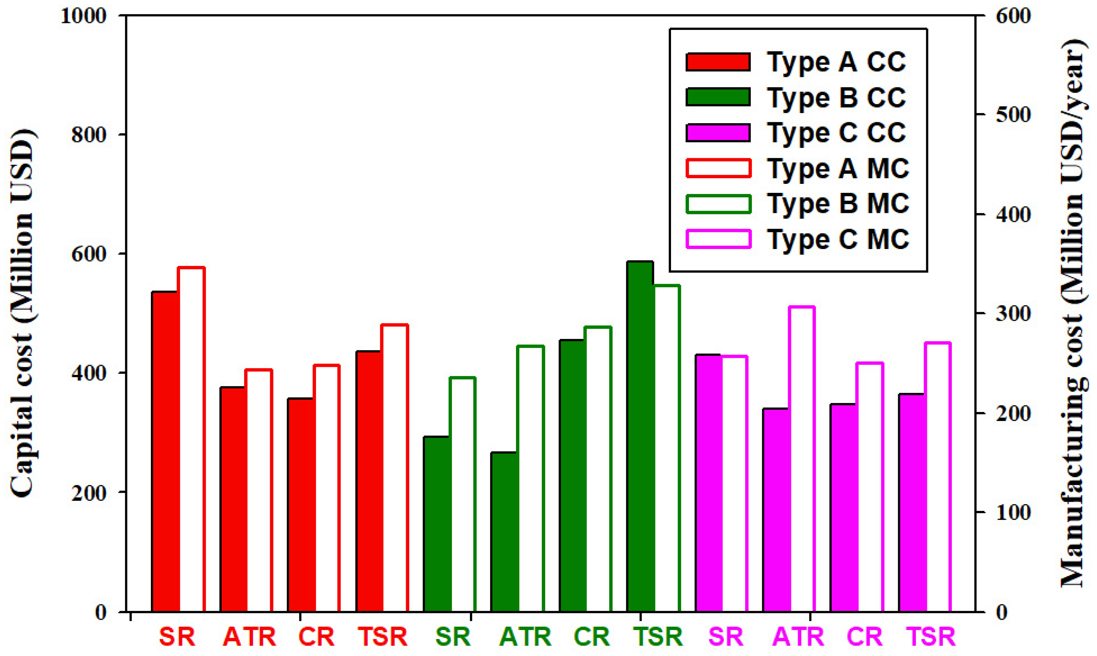
  • The utilization of CO2 in methanol production does not necessarily lead to the increase of capital cost or manufacturing cost.
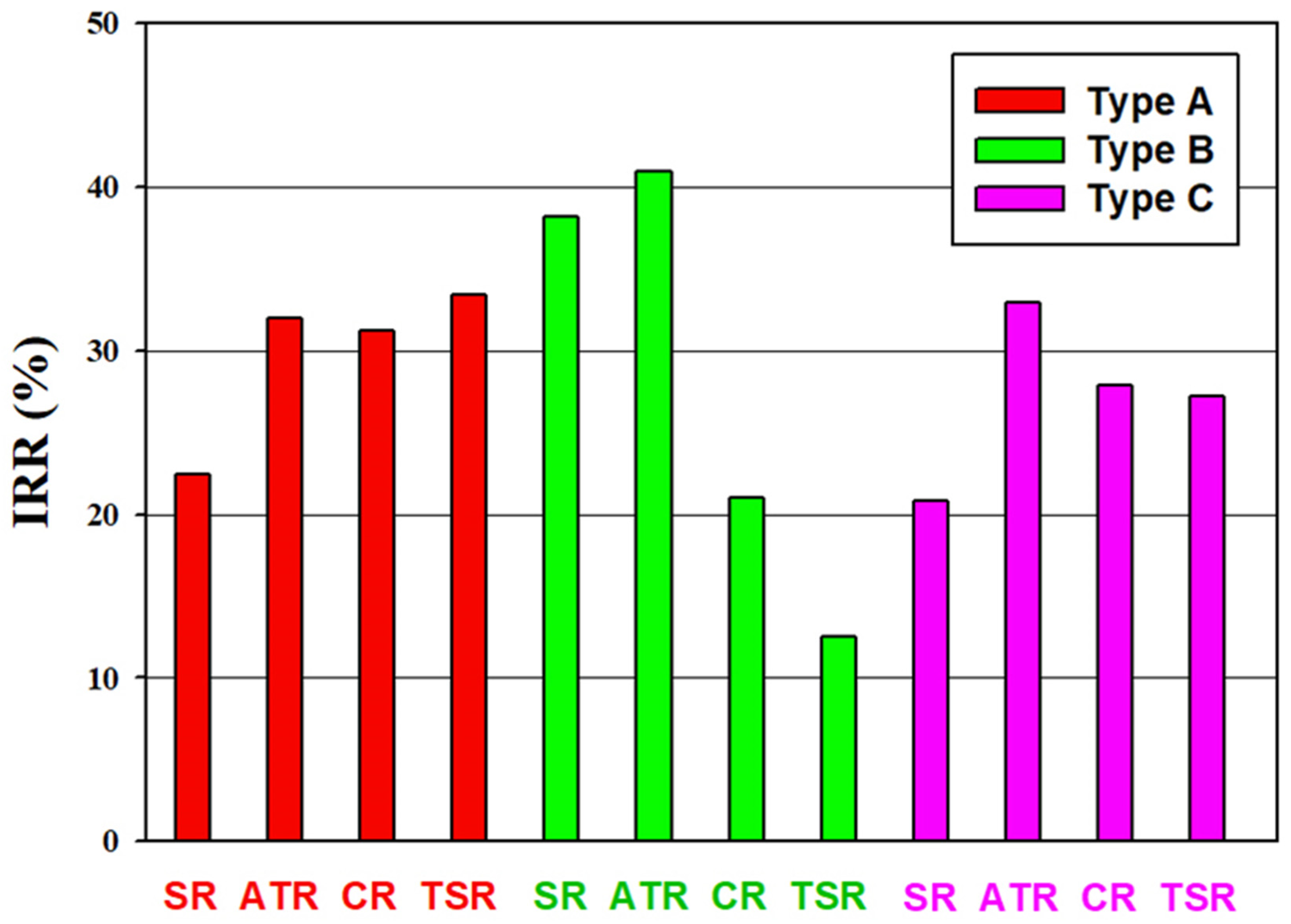
  • The utilization of CO2 in methanol production does not necessarily lead to a reduction of the profit. The B-ATR process has the highest IRR with a value of 41%. The process with the lowest IRR is B-TSR with a value of 12.5%.
The use of CO2 as the feedstock to the autothermal reforming in the methanol production process gives the best performance index, including the highest amount of CO2 usage, the highest net carbon dioxide reduction (0.23 kg CO2/kg methanol) as well as the highest internal rate of return (41%). This study concludes that the utilization of CO2 in the industrial methanol process can realize substantial carbon reduction and is beneficial to process economics.

Author Contributions

Proposed the concept, H.C. and D.S.-H.W.; developed the process flowsheet and the methodology for analysis, Y.-H.C. and H.C.; conducted the simulation and data analysis, Y.-C.C. and C.-M.C. All authors contributed to the results, discussion, and conclusions. Y.-H.C. and H.C. prepared the manuscript.

Funding

This research was funded by the Ministry of Economic Affairs of Taiwan, grant number 109-EC-17-A-22-1466.

Conflicts of Interest

The authors declare no conflicts of interest.

Appendix A

The design constraints of each alternative process with the corresponding process variables adjusted to meet the constraints are listed in Table A1.
Table A1. Design constraints and adjusted variables of Type A processes.
Design SpecificationAdjusted Variable
A-SR
SR-methane conversion = 90%Steam feed rate
Methanol production rateMethane feed rate
M value of make-up-gas to methanol synthesis = 2.05Hydrogen purge rate from PSA-1
Overall process mass balance of methaneSplit fraction of F-2 vapor outlet
A-ATR
Adiabatic operation of ATROxygen feed rate
Methanol production rateMethane feed rate
ATR-methane conversion = 90%Steam feed rate
M value of make-up-gas to methanol synthesis = 2.05Hydrogen purge rate from PSA
Overall process mass balance of methaneSplit fraction of F-2 vapor outlet
A-CR
Adiabatic operation of ATROxygen feed rate
Methanol production rateMethane feed rate
ATR-methane conversion = 90%Steam feed rate
SMR-methane conversion = 30%Steam feed split ratio
M value of make-up-gas to methanol synthesis = 2.05Methane feed split ratio
Overall process mass balance of methaneSplit fraction of F-2 vapor outlet
A-TSR
Adiabatic operation of ATROxygen feed rate
Methanol production rateMethane feed rate
ATR-methane conversion = 90%Steam feed rate
SMR-methane conversion = 30%Steam feed split ratio
M value of make-up-gas to methanol synthesis = 2.05Hydrogen purge rate from PSA-1
Overall process mass balance of methaneSplit fraction of F-2 vapor outlet
Table A2. Design constraints and adjusted variables of Type B processes.
Design SpecificationAdjusted Variable
B-SR
SR-methane conversion = 90%Steam feed rate
Methanol production rateMethane feed rate
M value of make-up-gas to methanol synthesis = 2.05Hydrogen purge rate from PSA-1
Overall process mass balance of methaneSplit fraction of F-2 vapor outlet
B-ATR
Adiabatic operation of ATROxygen feed rate
Methanol production rateMethane feed rate
ATR-methane conversion = 90%Steam feed rate
M value of make-up-gas to methanol synthesis = 2.05Hydrogen purge rate from PSA
Overall process mass balance of methaneSplit fraction of F-2 vapor outlet
B-CR 1
Adiabatic operation of ATROxygen feed rate
Methanol production rateMethane feed rate
ATR-methane conversion = 90%Steam feed rate
SMR-methane conversion = 30%Steam feed split ratio
M value of make-up-gas to methanol synthesis = 2.05Hydrogen purge rate from PSA-1
Overall process mass balance of methaneSplit fraction of F-2 vapor outlet
B-TSR
Adiabatic operation of ATROxygen feed rate
Methanol production rateMethane feed rate
ATR-methane conversion = 90%Steam feed rate
SMR-methane conversion = 30%Steam feed split ratio
M value of make-up-gas to methanol synthesis = 2.05Hydrogen purge rate of PSA-1
Overall process mass balance of methaneSplit fraction of F-2 vapor outlet
1 Methane feed split ratio to the SR was fixed at 0.5.
Table A3. Design constraints and adjusted variables of Type C processes.
Design SpecificationAdjusted Variable
C-SR
SR-methane conversion = 90%Steam feed rate
Methanol production rateMethane feed rate
M value of make-up-gas to methanol synthesis = 2.05CO2 feed rate
Overall process mass balance of methaneSplit fraction of F-2 vapor outlet
C-ATR
Adiabatic operation of ATROxygen feed rate
Methanol production rateMethane feed rate
ATR-methane conversion = 90%Steam feed rate
M value of make-up-gas to methanol synthesis = 2.05CO2 feed rate
Overall process mass balance of methaneSplit fraction of F-2 vapor outlet
C-CR 1
Adiabatic operation of ATROxygen feed rate
Methanol production rateMethane feed rate
ATR-methane conversion = 90%Steam feed rate
SMR-methane conversion = 30%Steam feed split ratio
M value of make-up-gas to methanol synthesis = 2.05CO2 feed rate
Overall process mass balance of methaneSplit fraction of F-2 vapor outlet
C-TSR
Adiabatic operation of ATROxygen feed rate
Methanol production rateMethane feed rate
ATR-methane conversion = 90%Steam feed rate
SMR-methane conversion = 30%Steam feed split ratio
M value of make-up-gas to methanol synthesis = 2.05CO2 feed rate
Overall process mass balance of methaneSplit fraction of F-2 vapor outlet
1 Methane feed split ratio to the SR was fixed at 0.5.

Appendix B

Table A4. Stream data of B-ATR process.
Stream Number.12345678
Temp (°C)20210004040260404040
Press (bar)4040404070707070
Mole flow (kmol/h)16,18817,846344214,46015,719357812,1404290
Mass flow (t/h)265.46265.4673.5191315111204188
Mole Flow (kmol/h)
CH44641.8464.249.45465.7467.78.4461.9461.9
H2O2012.43053.73025.927.9181.143.091.451.45
CO04901.379.14822.41244.814.891236.51236.5
CO21989.31090.4283.4807.71770.880.91638.41638.4
H208336.90.00038336.98750.126.598721.7872.17
O22902.90000000
CH3OH00003304.53220.780.480.4
Stream Number910111213141516
Temp (°C)3737409837376498
Press (bar)70707002211
Mole flow (kmol/h)4155269383740123260134323228
Mass flow (t/h)115747.78.1104.94.1103.50.5
Mole Flow (kmol/h)
CH4447.322.7000.38.10.30
H2O1.40.140043.00.0915.127.9
CO1197.453.73000.2614.630.260
CO21586.58116.20016.564.416.50
H2844.5853.973837.034012.50.2126.380.210
O200000000
CH3OH77.8622.94003200.320.432000.3

References

  1. The Global Status of CCS. 2018. Available online: https://www.globalccsinstitute.com/resources/global-status-report/ (accessed on 16 September 2019).
  2. Centi, G.; Iaquaniello, G.; Perathoner, S. Can we afford to waste carbon dioxide? Carbon dioxide as a valuable source of carbon for the production of light olefins. ChemSusChem 2011, 4, 1265–1273. [Google Scholar] [CrossRef] [PubMed]
  3. Quadrelli, E.A.; Centi, G.; Duplan, J.-L.; Perathoner, S. Carbon dioxide recycling: Emerging large-scale technologies with industrial potential. ChemSusChem 2011, 4, 1194–1215. [Google Scholar] [CrossRef] [PubMed]
  4. Cuéllar-Franca, R.M.; Azapagic, A. Carbon capture, storage and utilization technologies: A critical analysis and comparison of their life cycle environmental impacts. J. CO2 Util. 2015, 9, 82–102. [Google Scholar] [CrossRef]
  5. Alper, E.; Orhan, O.Y. CO2 utilization: Developments in conversion processes. Petroleum 2017, 3, 109–126. [Google Scholar] [CrossRef]
  6. Wurzel, T. Lurgi MegaMethanol Technology—Delivering the building blocks for future fuel and monomer demand. In Proceedings of the DGMK International Conference Synthesis Gas Chemistry, Dresden, Germany, 4–6 October 2006. [Google Scholar]
  7. Bertau, M.; Offermanns, H.; Plass, L.; Schmidt, F.; Wernicke, H.-J. Methanol: The Basic Chemical and Energy Feedstock of the Future; Springer: Berlin/Heidelberg, Germany, 2014. [Google Scholar]
  8. Aresta, M. Carbon Dioxide as Chemical Feedstock; Wiley-VCH: Weinheim, Germany, 2010. [Google Scholar]
  9. Lee, S. Methanol synthesis from syngas. In Handbook of Alternative Fuel Technologies; Lee, S., Speight, J.G., Loyalka, S.K., Eds.; CRC Press: Boca Raton, FL, USA, 2007. [Google Scholar]
  10. König, P.; Göhna, H. Process of Producing Methanol. U.S. Patent 5,631,302, 20 May 1997. [Google Scholar]
  11. Joo, O.-S.; Jung, K.-D.; Moon, I.; Rozovskii, A.Y.; Lin, G.I.; Han, S.-H.; Uhm, S.-J. Carbon dioxide hydrogenation to form methanol via a reverse-water-gas-shift reaction (the CAMERE Process). Ind. Eng. Chem. Res. 1999, 38, 1808–1812. [Google Scholar] [CrossRef]
  12. Carbon Recycling International, CO2-to-Methanol Plant Erected in Germany. Available online: https://www.carbonrecycling.is/news/2018/11/1/cri-co2-to-methanol-plant-erected-in-germany-ck6nx (accessed on 16 September 2019).
  13. Aasberg-Petersen, K.; Dybkjær, I.; Ovesen, C.V.; Schjødt, N.C.; Sehested, J.; Thomsen, S.G. Natural gas to synthesis gas—catalysts and catalytic processes. J. Nat. Gas. Sci. Eng. 2011, 3, 423–459. [Google Scholar] [CrossRef]
  14. Ulber, D. A guide to: Methane reforming. Chem. Eng. 2015, 122, 40–46. [Google Scholar]
  15. Usman, M.; Wan Daud, W.M.A.; Abbas, H.F. Dry reforming of methane: Influence of process parameters—A review. Renew. Sust. Energ. Rev. 2015, 45, 710–744. [Google Scholar] [CrossRef]
  16. Arora, S.; Prasad, R. An overview on dry reforming of methane: Strategies to reduce carbonaceous deactivation of catalysts. RSC Adv. 2016, 6, 108668–108688. [Google Scholar] [CrossRef]
  17. Song, C.; Pan, W. Tri-reforming of methane: A novel concept for catalytic production of industrially useful synthesis gas with desired H2/CO ratios. Catal. Today 2004, 98, 463–484. [Google Scholar] [CrossRef]
  18. Noureldin, M.M.B.; Elbashir, N.O.; El-Halwagi, M.M. Optimization and selection of reforming approach for syngas generation from natural/shale gas. Ind. Eng. Chem. Res. 2014, 53, 1841–1855. [Google Scholar] [CrossRef]
  19. Wiesberg, I.L.; de Medeiros, J.L.; Alves, R.M.B.; Coutinho, P.L.A.; Araújo, O.Q.F. Carbon dioxide management by chemical conversion to methanol: Hydrogenation and bi-reforming. Energy Convers. Mgmt. 2016, 125, 320–335. [Google Scholar] [CrossRef]
  20. Pérez-Fortes, M.; Schöneberger, J.C.; Boulamanti, A.; Tzimas, E. Methanol synthesis using captured CO2 as raw material: Techno-economic and environmental assessment. Appl. Energy 2016, 161, 718–732. [Google Scholar] [CrossRef]
  21. Luu, M.T.; Milani, D.; Bahadori, A.; Abbas, A. A comparative study of CO2 utilization in methanol synthesis with various syngas production technologies. J. CO2 Util. 2015, 12, 62–76. [Google Scholar] [CrossRef]
  22. Milani, D.; Khalilpour, R.; Zahedi, G.; Abbas, A. A model-based analysis of CO2 utilization in methanol synthesis plant. J. CO2 Util. 2015, 10, 12–22. [Google Scholar] [CrossRef]
  23. Blumberg, T.; Morosuk, T.; Tsatsaronis, G. Exergy-based evaluation of methanol production from natural gas with CO2 utilization. Energy 2017, 141, 2528–2539. [Google Scholar] [CrossRef]
  24. Zhang, Y.; Cruz, J.; Zhang, S.; Lou, H.H.; Benzon, T.J. Process simulation and optimization of methanol production coupled to tri-reforming process. Int. J. Hydrogen Energy 2013, 38, 13617–13630. [Google Scholar] [CrossRef]
  25. Aspen Technology, Inc. Aspen Plus® V10; Aspen Technology, Inc.: Bedford, MA, USA, 2018. [Google Scholar]
  26. Linnhoff, B.; Mason, D.R.; Wardle, I. Understanding heat exchanger networks. Comput. Chem. Eng. 1979, 3, 295–302. [Google Scholar] [CrossRef]
  27. United States Energy Information Administration. How Much Carbon Dioxide Is Produced Per Kilowatthour of U.S. Electricity Generation? Available online: https://www.eia.gov/tools/faqs/faq.php?id=74&t=11 (accessed on 31 August 2019).
  28. Bolland, O.; Sæther, S. New concepts for natural gas fired power plants which simplify the recovery of carbon dioxide. Energy Convers. Mgmt. 1992, 33, 467–475. [Google Scholar] [CrossRef]
  29. Economic indicators. Chem. Eng. 2017, 124, 64.
  30. United States Energy Information Administration. Henry Hub Natural Gas Spot Price. Available online: https://www.eia.gov/dnav/ng/hist/rngwhhdm.htm (accessed on 31 August 2019).
  31. Turton, R.; Bailie, R.C.; Whiting, W.B.; Shaeiwitz, L.A.; Bhattacharyya, D. Analysis, Synthesis, and Design of Chemical Processes, 4th ed.; Prentice Hall: New York, NY, USA, 2012. [Google Scholar]
  32. Choi, S.; Park, J.; Han, C.; Yoon, E.S. Optimal design of synthesis gas production process with recycled carbon dioxide utilization. Ind. Eng. Chem. Res. 2008, 47, 323–331. [Google Scholar] [CrossRef]
  33. Basye, L.; Swaminathan, S. Hydrogen Production Costs—A Survey; DOE/GO/10170-T18; USDOE: Washington, DC, USA, 1997.
  34. Bonner, B. Current Hydrogen Cost. DOE Hydrogen and Fuel Cell Technical Advisory Committee; 30 October 2013. Available online: https://www.hydrogen.energy.gov/pdfs/htac_oct13_10_bonner.pdf (accessed on 16 September 2018).
  35. Methanex Methanol Price Sheet. Available online: https://www.methanex.com/our-business/pricing (accessed on 31 July 2018).
  36. Onel, O.; Niziolek, A.M.; Floudas, C.A. Optimal production of light olefins from natural gas via the methanol intermediate. Ind. Eng. Chem. Res. 2016, 55, 3043–3063. [Google Scholar] [CrossRef]
  37. National Energy Technology Laboratory. Analysis of Natural Gas-to-Liquid Transportation Fuels via Fischer–Tropsch; DOE/NETL-2013/1597; USDOE: Washington, DC, USA, 2013.
  38. Phillips, S.; Tarud, J.K.; Biddy, M.J.; Dutta, A. Gasoline from Wood via Integrated Gasification, Synthesis, and Methanol-to-Gasoline Technologies; USDOE Contract DE-AC36-08GO28308; National Renewable Energy Laboratory: Golden, CO, USA, 2011.
  39. Larson, E.D.; Jin, H.; Celik, F.E. Large-scale gasification-based coproduction of fuels and electricity from switchgrass. Biofuel. Bioprod. Biorefin. 2009, 3, 174–194. [Google Scholar] [CrossRef]
Figure 1. Alternative natural gas-based methanol process schemes employing different types of reforming and different locations of CO2 input. The four types of reforming are steam reforming (SR), autothermal reforming (ATR), combined reforming (CR), and two-step reforming (TSR). The three types of CO2 utilization are Type A—no use of CO2, Type B—CO2 input to the reformer, and Type C—CO2 input to the methanol synthesis reactor.
Energies 12 04322 g001
Figure 2. Process flow diagram of the A-SR process. The process does not utilize CO2 as a raw material and steam reforming is employed for the generation of syngas.
Energies 12 04322 g002
Figure 3. Process flow diagram of the B-ATR process. The process utilizes CO2 as a reforming step raw material and autothermal reforming is employed for the generation of syngas.
Energies 12 04322 g003
Figure 4. Process flow diagram of the C-CR process. The process utilizes CO2 as a methanol step raw material and employs combined reforming, where a steam reformer and autothermal reformer are connected in series-parallel configuration, for the generation of syngas.
Energies 12 04322 g004
Figure 5. Process flow diagram of the C-TSR process. The process utilizes CO2 as a methanol step raw material and employs two step reforming, where a steam reformer and autothermal reformer are connected in series configuration, for the generation of syngas.
Energies 12 04322 g005
Figure 6. Net energy consumption of alternative processes. Energy consumption is presented as equivalent work (We). Positive or negative results represent energy, which must be provided to or generated from the process, respectively. The three types of CO2 utilization are Type A—no use of CO2, Type B—CO2 input to the reformer, and Type C—CO2 input to the methanol synthesis reactor.
Energies 12 04322 g006
Figure 7. Exergy analysis results of alternative processes. Exergy losses from different types of equipment are shown in different colors with EX, D and R stand for heat exchange operations, distillation columns and reactors, respectively. The three types of CO2 utilization are Type A—no use of CO2, Type B—CO2 input to the reformer, and Type C—CO2 input to the methanol synthesis reactor.
Energies 12 04322 g007
Figure 8. Net CO2 reduction (NCR) of alternative processes. The NCR takes into account the CO2 emission due to CO2 flows via process inlet and outlet streams as well as the heat and work transfers.
Energies 12 04322 g008
Figure 9. Capital cost and manufacturing cost of alternative processes. CC: capital cost, MC: annual manufacturing cost.
Energies 12 04322 g009
Figure 10. Cost distributions of the B-ATR process. (a) Equipment costs, (b) raw material and utility costs. The reformers constitute the major part of the total equipment cost. The methane feedstock cost contributes about half and the CO2 cost contributes a very small portion of the total operation cost.
Energies 12 04322 g010
Figure 11. Internal rate of return of alternative processes. All the alternative processes are profitable in terms of IRR.
Energies 12 04322 g011
Table 1. Feed rates of feedstock to alternative processes (kmol/h).
ProcessCH4SteamOxygenCO2
A-SR4270787500
B-SR3085505601322
C-SR3275844801224
A-ATR4052280120870
B-ATR4642201229032233
C-ATR542767283020246
A-CR3936431017340
B-CR4381260019841717
C-CR368456811737402
A-TSR4684456814780
B-TSR3732559714611594
C-TSR353154031294523
Table 2. Prices assumed for methanol production.
MaterialPriceUnitReference
Methane132$/t[30]
Steam (30 bar)28.85$/t[31]
Oxygen 125$/t[28,31]
Carbon dioxide 23$/t[32]
Hydrogen750$/t[33,34]
Methanol480$/t[35]
Fuel gas 32.65$/GJ[30]
UtilityPriceUnitReference
Electricity0.06$/kWh[31]
Steam (LP/MP/HP)14.05/14.83/17.7$/GJ[31]
Natural gas2.65$/GJ 4[30]
Cooling water0.354$/GJ[31]
1 Estimated by the required power for unit oxygen production is 0.42 kWh/kg [28] and the price of electricity. 2 Transportation cost from a nearby CO2 capture plant. 3 Based on the heating value price of natural gas. 4 Lower heating value.

