Article

Modeling of Light Pipes for the Optimal Disposition in Buildings

by
Cristina Baglivo
1,*,
Marina Bonomolo
2 and
Paolo Maria Congedo
1
1
Dipartimento di Ingegneria dell’Innovazione, Università of Salento, 73100 Lecce, Italy
2
Dipartimento di Ingegneria, Università di Palermo, Viale delle Scienze Ed. 9, 90128 Palermo, Italy
*
Author to whom correspondence should be addressed.
Energies 2019, 12(22), 4323; https://doi.org/10.3390/en12224323
Submission received: 1 October 2019 / Revised: 6 November 2019 / Accepted: 12 November 2019 / Published: 13 November 2019

Abstract

:
A light pipe is an excellent solution to transport and distribute daylight into environments without or with little lighting, guaranteeing comfort inside the rooms. As stated in the literature, the evaluation of the performances of light pipes presents numerous complexities, making the work very difficult for technicians and designers. This study is aimed to present a methodology that is able to identify the potential of light pipes using indices such as daylight autonomy (DA), continuous daylight autonomy (DAc), and useful daylight illuminance (UDI). This paper presents an analysis of daylight obtained by several configurations of simple models of light pipes installed into a 5 × 5 m plant area room. All simulations are carried out in a DAYSIM environment, which allows calculating the annual availability of daylight based on a RADIANCE raytracer backward. Several daylight conditions were analyzed for different light pipe configurations, considering different pipe lengths and a variable number of light pipes. The light pipes are tested also in the horizontal position, for different orientations. The results of all the combinations were compared with the performances of a window with dimensions equal to 1/8 of the internal surface, which was in accordance with the minimum value to be guaranteed by the Italian Regulation (D.M. 5 July 1975 n. 190) for different orientations. The results indicated a difference in daylight distribution, showing a strong correlation between the percentage levels of DA and DAc with the length and number of pipes, during different periods of the year. The simulated model is strongly influenced by the aspect ratio (R = diameter/length). The results show that the illuminance levels decrease drastically, increasing the length.

Graphical Abstract

1. Introduction

Nowadays, climate change is considered one of the main challenges to be overcome globally [1]. In recent years, numerous strategies have been developed around the world to reduce the negative effects of climate changes and tackle global warming due to greenhouse gas emissions, especially from the building sector. It is well known that the identification of the optimal configuration of building components can significantly reduce the excessive energy consumption in buildings [2]. For this reason, several studies have examined the implementation of new methodologies to guarantee high-energy performance in the buildings [3,4,5].
The most critical elements of buildings are the glazed openings in terms of solar gains, heat losses, and thermal bridges [6]. The need to reduce energy consumption and at the same time guarantee comfortable vision has led to the development of new components, systems, and technologies. Daylighting techniques are widely used in building lighting to ensure energy savings and visual comfort [7]. The visual ability is the result of an adaptation of the human eyes to the light over time, hence the important role of the psychophysical levels of the daylight for many activities. Indeed, the daylight condition can influence the occupants both psychologically and physically (in terms of problems of the visual system). In this last case, the user can have problems with the visual system according to the sensitivity of the human eye (e.g., caused by the glare condition [8,9] and other non-visual effects (e.g., the melatonin [10]).
Today, the role played by daylight on the state of mind, on physiology, and on the well-being of human beings seems to be certain, especially after the discoveries presented in [11,12]. These studies [13,14] demonstrate the role of biological lighting, as well as its effects on the circadian system and productivity. Indeed, lighting can influence many aspects and functions of the body such as the suppression of the hormone melatonin, sensitivity to different wavelengths according to the photoreceptor cells from the eye to the brain, the regulation of some important hormones through regular light–dark rhythms, etc. There are still no simple rules to guarantee, for any type of activity, good daylight in a small space [15]. The openings should be designed in relation to the overall volume, the distribution of the spaces, and the characteristics of the façade. On the other hand, they should be proportionate and placed in such a way as to ensure, at different times of the day, a comfortable distribution of daylight, while avoiding dazzling phenomena [16].
During the design phase to ensure an optimal exploitation of light, it is important to satisfy the visual and architectural needs, which influence the functional distribution of spaces and visual well-being. It is also necessary to consider the building energy behavior, the use of artificial light, and the integration of related control systems [17]. Firstly, the availability of daylight cannot be controlled and fixed by the designer; its distribution and intensity are functions of the considered season and latitude. It is also necessary to consider the architectural features of the structure, its orientation, the optical characteristics of the room surfaces, the furniture, and all the boundary conditions [18]. The cited advantages of daylight have led to the development of new systems for daylight. In this paper, the use of light pipes has been studied.
Light pipes are technological systems that allow the introduction of daylight from the exterior of a building into indoor environments, which is useful for spaces with or without glazing openings that are often closed and dark.
Light pipes consist of three components, each of which is important for the introduction, transmission, and diffusion of light into the environment. The collector is positioned in the upper and external part of the light pipe; its function is to intercept and introduce the light rays coming from the outside. The pipe allows light to be transported to the interior space; usually, reflective films are applied to the inner surface to improve its function. The third component is the diffuser, which is positioned inside the interior spaces and has the function of diffusing light into the environment.
The aim of this paper is to describe with a reliable simulation approach the potential and performance of light pipes that are able to transport light through vertical or horizontal paths into rooms that cannot receive daylight directly. The spatial and temporal variability of different lighting factors has been analyzed for different geometric configurations, pipe lengths, and numbers of pipes. The methodology is based on the use of two programs: DAYSIM [19] and Google Sketchup [20], which were used synergistically in a parametric study to evaluate the lighting performance. DAYSIM allows calculating the annual availability of daylight based on RADIANCE raytracer backward, and it has been chosen to perform daylighting analysis as it accurately estimates climate-based daylight metrics.

2. An Overview on Light Pipes

Light pipes have the main advantage of providing daylight as well in spaces where it is not possible to install traditional daylight systems such as windows. So, for this reason, they provide all the daylight advantages such as the visual comfort and, as demonstrated in the energy analysis, the reduction of the use of the electricity absorbed by the artificial lighting systems.
They can be applied in residential, commercial [21], school buildings [22], offices [23], and industrial buildings [24]. The advantages of light pipes are the exploitation of solar gains in the winter, the protection against glare, the possibility of bringing daylight into environments without windows, the uniform distribution of daylight, the increasing of the overall availability of daylight, the absence of the chromatic alteration of daylight, the possibility of applying, even in existing buildings, energy savings on artificial light, the improvement of visibility in relation to the best quality of light (sunlight), and the well-being of the occupants [25]. The disadvantages are the non-constant behavior of collection systems during the year, the reduced availability of daylight (in case of a partially covered sky), the lack of visual contact with the outside, and the higher costs.
The light pipes consist of three components: the external collector, the pipe, and the diffuser. Each component of tubular light tubes plays an important role in the overall efficiency and quality of the light received within the environment [26].
The study [27] has focused on the influence of two different typologies of diffuser with prismatic and radial geometry. The experimental analysis showed the uniform spatial light distribution of the first one, and the less uniform distribution of light of the second.
In [28], the light and energy performances of a tubular light guide system have been improved thanks to the presence of a Lambertian diffuser and a clear glass positioned at its base.
The study [21] shows that the best performances are obtained with pipes that are straight and short, with low aspect ratios and with larger diameter.
Several applications are developed to simulate the behavior of the light pipes [29]. Different models permit describing the behavior of light pipes, based on theoretical or semi-empirical models. The first are based on geometrical optics analysis, while the second is based on a combination of theoretical and experimental analysis. The study [30] provides support to a problem discussed in the literature concerning the accuracy of semi-empirical models in the reproduction of the performance of light tubes, proposing the use of a model generator called HEMERA. The approach was based on a Galilean sequence; after the observation of the experimental case, they better understand the phenomena and validate the developed method.
Ciugudeanu et al. [31] used DIALux for the analysis of a passive tubular daytime driving system of a case study placed in Cluji-Napoca, Romania.
One type of software that is widely used in the literature is HOLIGILM. In [32], HOLIGIM was used to reproduce the isolux models of tubular light guides in order to analyze several daylight conditions in tropical interiors. The study [33] used HOLIGILM for the reproduction of a physical model of cylindrical skylights for the evaluation of the influences of the optical properties of a dome, tube, and diffuser on the indoor daylight illuminance distribution.
Photopia and Radiance are used by [34] for the simulation of a light tube and fiber optic dish concentrator in a lecture room characterized by north-facing windows.
The algorithms implemented in EnergyPlus are analyzed by [35], it permits evaluating the daylighting and energy performances of a building.
Numerous studies are based both on measurements carried out on real cases and numerical simulations performed using different software.
In [36], the theoretical description of light transported inside the tubular light guide and its outgoing distribution based on the level of the ceiling was investigated. The results provided information that is useful for the implementation of the design requirements of these systems. They conducted a comparison with light measurements.
The study [37] compares with numerical and experimental analysis the performances of light pipes with and without bends, mathematically modeling the bend as a section of torus.
The study [38] presents a comparison between the light pipes modeled in EnergyPlus and ECOTECT environments with the real case reproduced in scale (1:5). The boundary conditions make the comparison very difficult, especially for the internal reflections. Data from EnergyPlus are underestimated near the pipes and overvalued away from them; data resulting from Ecotect are undervalued in all positions.
Several studies have contributed to the knowledge on tubular daylight transport.
The study [39] reports surveys on 13 working buildings, including commercial, healthcare, or academic buildings. The authors have affirmed that although there are adequate metrics for the quantitative analysis of systems available to designers, robust design criteria have yet to be developed. The daylight autonomy is considered by [40] in accordance with the specific requirements of different building uses. The study is focused on an office, a classroom, and a store. The office and classroom need at least 500 lx to guarantee an adequate visual comfort, while for the store, the limit is 300 lx. The analysis of the light distribution at different times permits investigating the behavior of light in an environment. The results demonstrate evidence that under sunny sky conditions, in the area under the diffuser, 300 lx is guaranteed for 5 h.
This paper aims to overcome the complexity in the simulation of light pipes, allowing the technicians and designers of a simple and versatile method to analyze the performances of light pipes.
The potential and performances of light pipes are investigated considering the daylight autonomy (DA), continuous daylight autonomy (DAc), and useful daylight illuminance (UDI). To reduce the complexity of the variables involved in the problem, the daylight analyses are conducted on a simple model of light pipes installed into a 5 × 5 m plant area room. All simulations are carried out in a DAYSIM environment, which allows calculating the annual availability of daylight based on RADIANCE raytracer backward.

3. Methodology

In this section, the applied methodology is presented. The following subsection describes the software used for the simulation, the calculated indices, and the analyzed case study.

3.1. The Simulation Software

This study focuses on the daylight analysis of a room modeled in a DAYSIM environment by using a standard overcast CIE (Commission Internationale de l’Éclairage) sky. It must be reminded that DAYSIM does not consider many important aspects of the light analysis of real light pipes (e.g., the diffuser part). DAYSIM is a validated daylight analysis software [41,42,43,44,45,46,47] that calculates the annual availability of daylight in buildings based on RADIANCE raytracer backward, and it is able to calculate the mentioned daylight indices. The simulated case study is described in Section 3.3. For detailed design, the software calculates a series of measures based on climate daytime lighting, including autonomy and useful daylighting.

3.2. Calculated Indices to Evaluate the Daylight Contribution

The simulation software was used to calculate a series of indices to evaluate daylighting. The most common is the daylight factor (DF), a static parameter, as the only valid criterion. This parameter does not consider the influence of extreme variability of the weather conditions and the surrounding environment. In 1975, Longmore [48] proposed the concept of average daylight factor (DFavg), which globally considers daylight in an environment and not in a timely manner. DFavg can be very useful in the early stages of design and can be linked directly to the size and position of the glazed surfaces. The daylight factor has many criticalities and limitations. For this reason, the literature proposed other parameters such as daylight autonomy (DA), made by the Association Suisse des Electriciens in 1989, continuous daylight autonomy (DAc), maximum daylight autonomy (DAmax), useful daylight illuminance (UDI), daylight saturation percentage (DSP), the annual light exposure (ALE), spatial daylight autonomy (sDA), and annual sunlight exposure (ASE).

3.3. Case Study Description

The case study is in Lecce, a city in the South of Italy with the following geographical coordinates: 40° north latitude, 18° east longitude, and 49 m of elevation from the sea. In order to carry out the lighting simulation used for the analysis presented in this study, a virtual model has been developed.
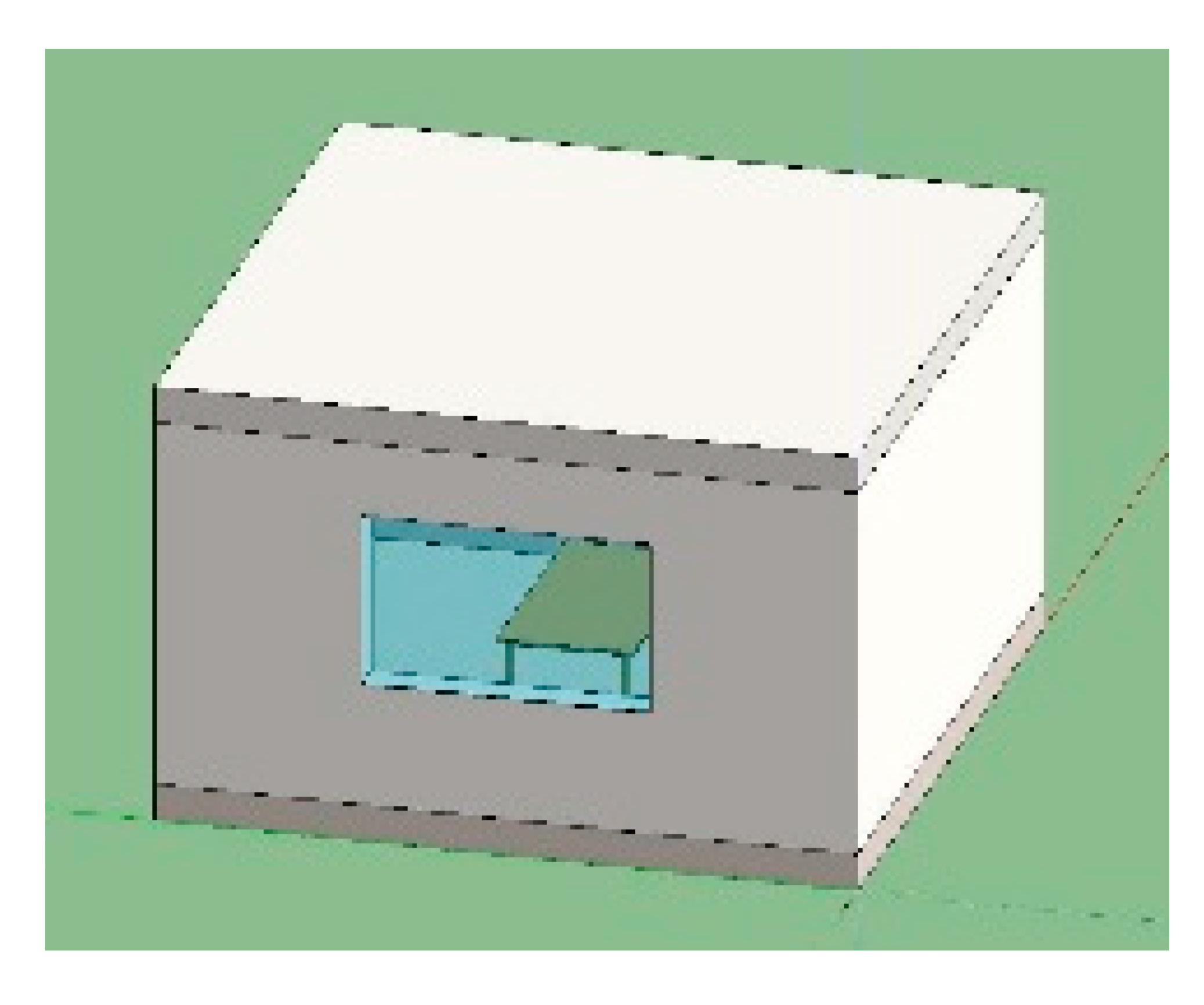
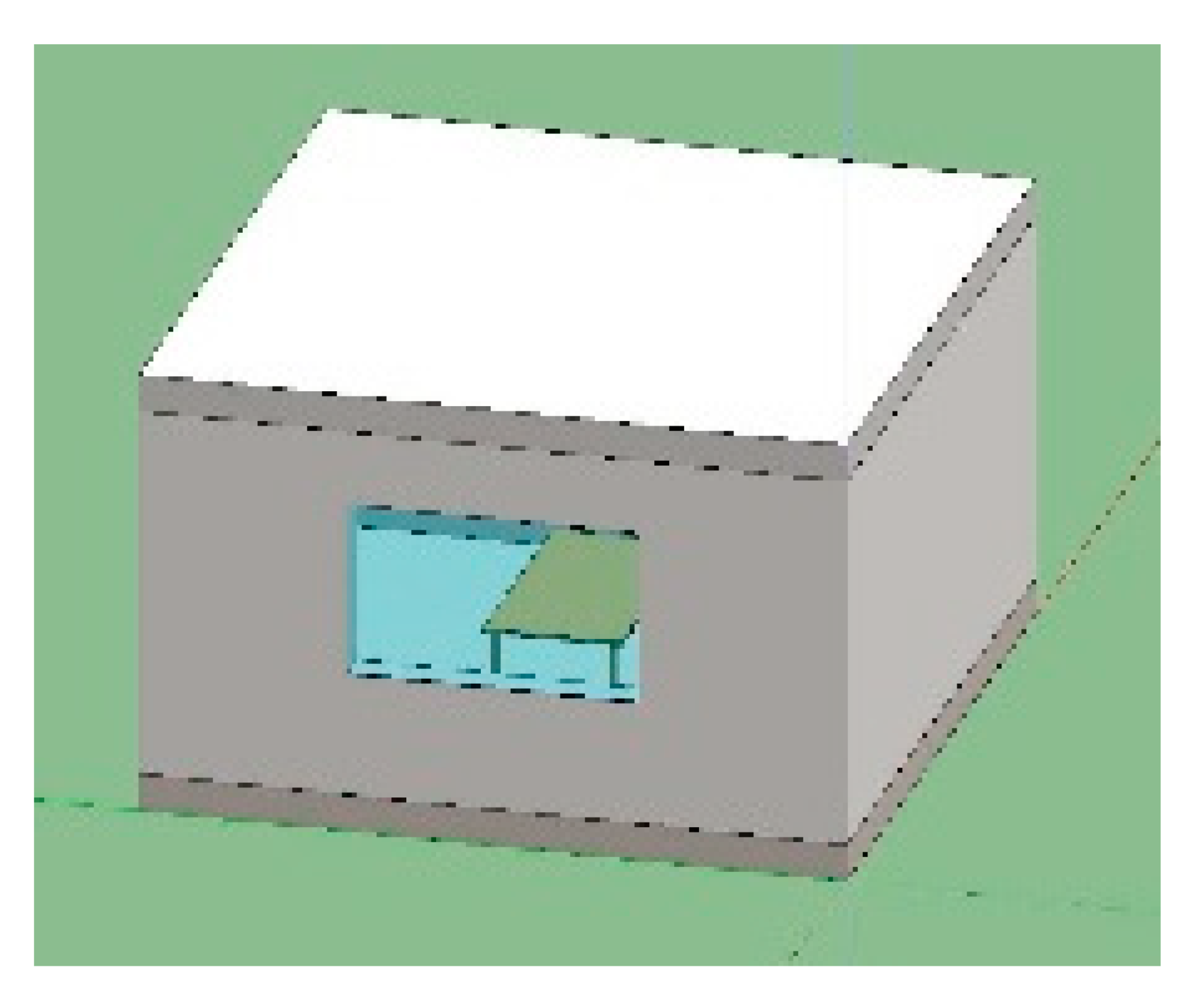
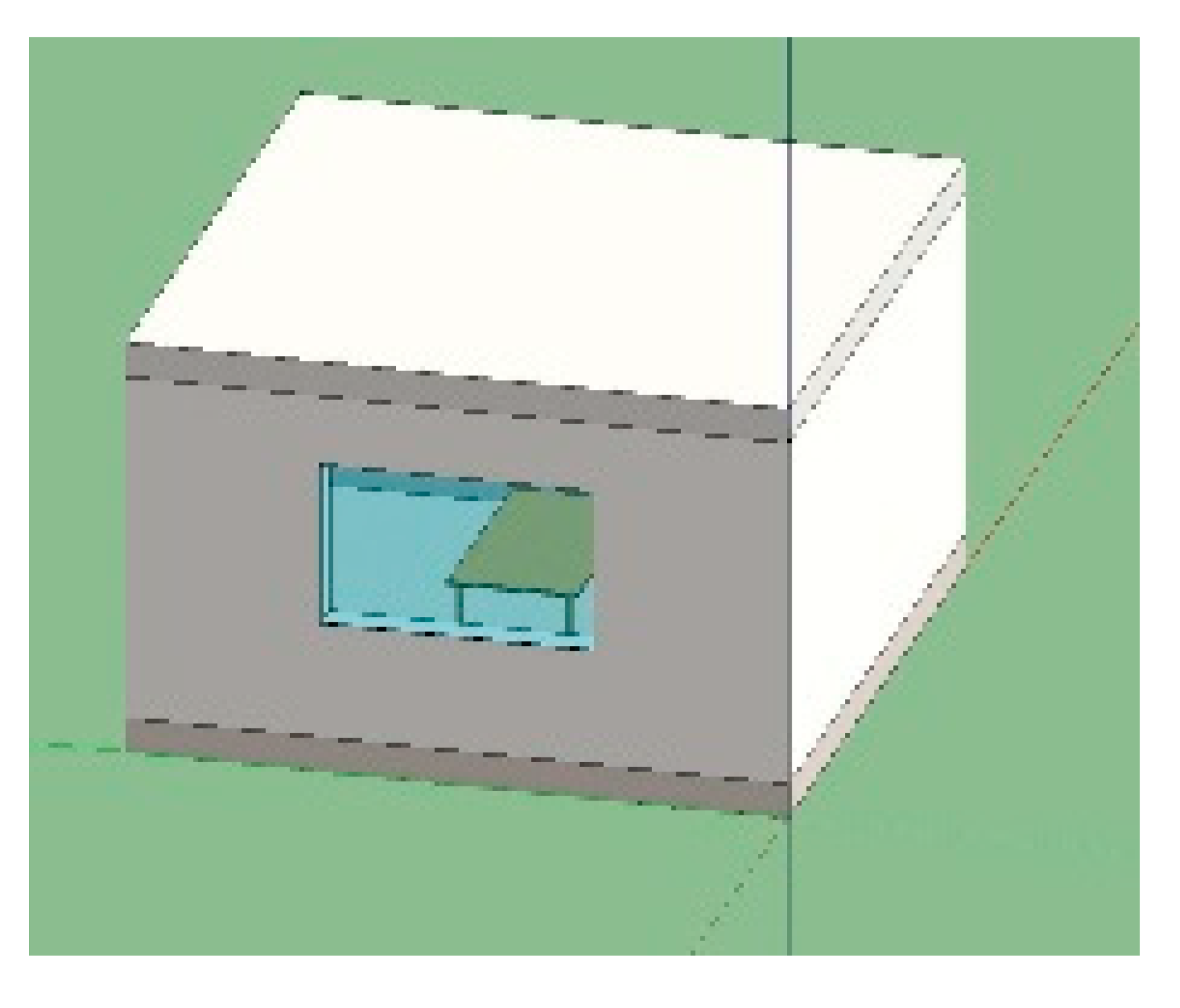
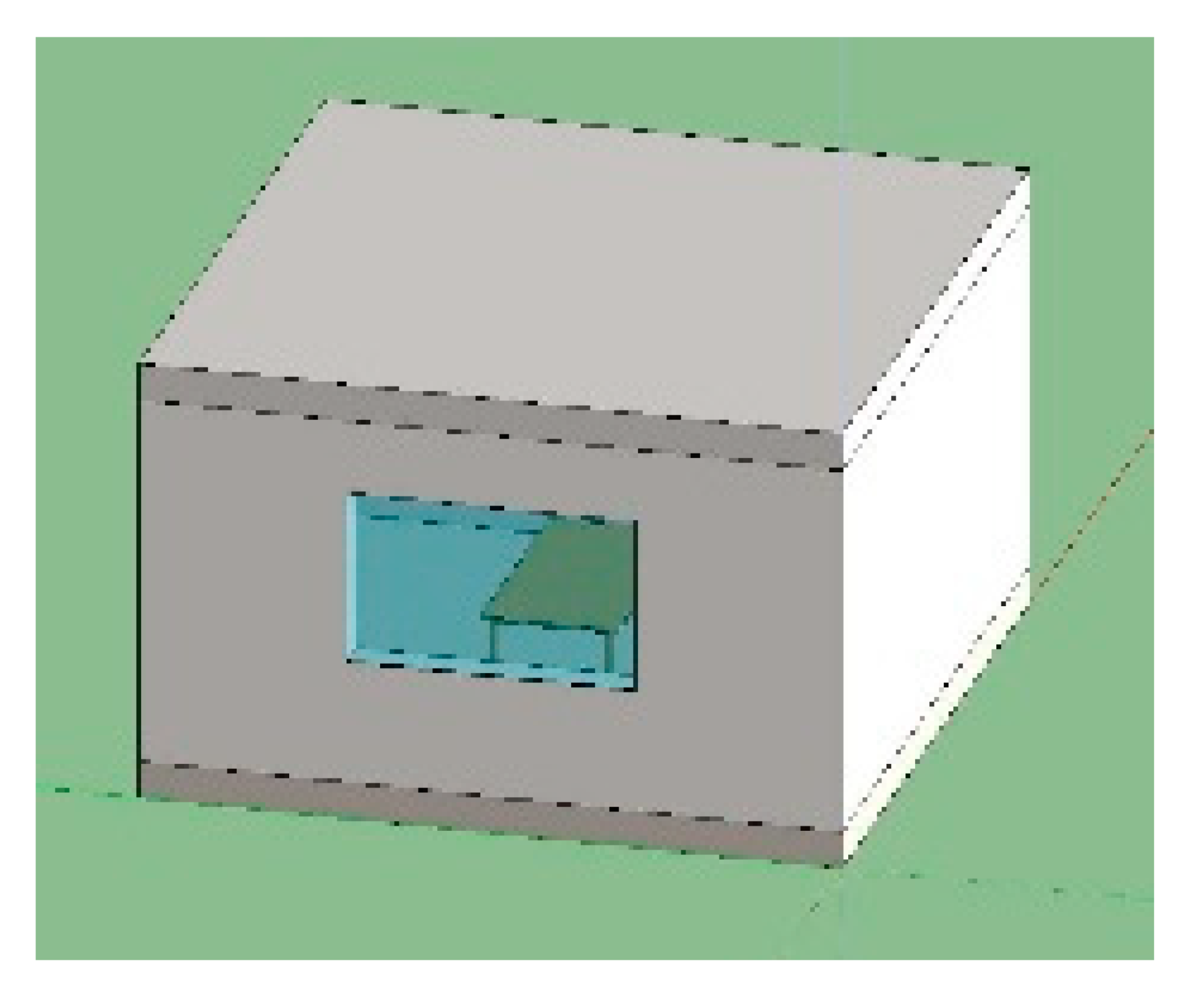
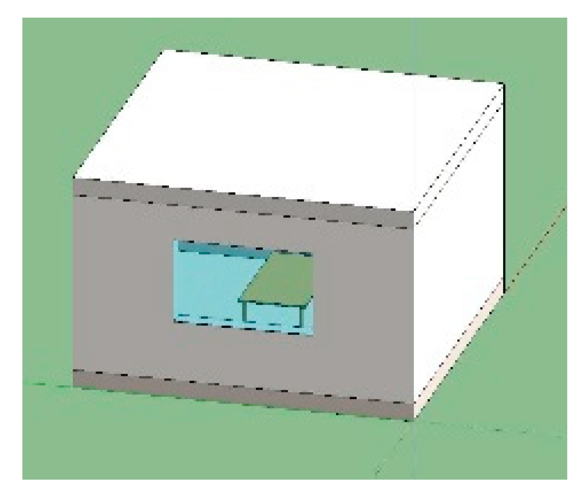
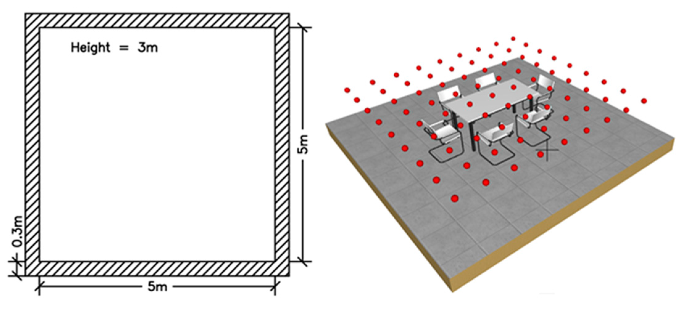
As shown in Figure 1, the room size is 5 × 5 m and 3 m height. The room has been simulated with and without windows and with light pipes.
The envelope consists of an inner coating of plaster with 90% reflectance and a tile floor with 70% reflectance. As reported in Figure 1, a total number of 81 sensors are placed every 0.50 m and 0.8 m from the floor.
Starting from this case study, the daylight performances of a window is evaluated. As reported in Table 1, combinations 1–4 are relative to the four window orientations analyzed. The window is positioned 1.1 m from the floor, and it has a dimension of 2.3 × 1.4 m, corresponding to 1/8 of the internal surface.
Table 2 shows 24 combinations of vertical light pipes, which consist of a Plexiglas outer dome, a diffuser with 90% light transmittance, and an aluminum pipe with 98% reflectance. A diameter of 0.55 m and three different lengths have been evaluated. The letters “D” and “G” define two configurations; “D” indicates the pipes in a diffused position, and “G” indicates the pipes in a grouped position.
To extend the analysis, some pipes have been positioned horizontally on the walls; the combinations are reported in Table 3.
The parameters analyzed were mainly the DA (daylight autonomy) and the DAc (daylight autonomy continuous). DA represents the percentage of hours during the year when the illuminance values overcome a predefined threshold [49]. The DAc provides more information. Indeed, DA does not evaluate lighting values below the established threshold. Rogers [50] developed continuous daylight autonomy (cDA), which further defines thresholds to specific visual tasks (e.g., below 500 lx). In this study, these two indices have been calculated by considering thresholds of both 200 lx and 500 lx.
The UDI2000 factor was considered to evaluate visual discomfort. This index represents the percentage of occupied time period when the plane illuminance level, due to the daylight contribution, is equal to or more than 2000 lx.
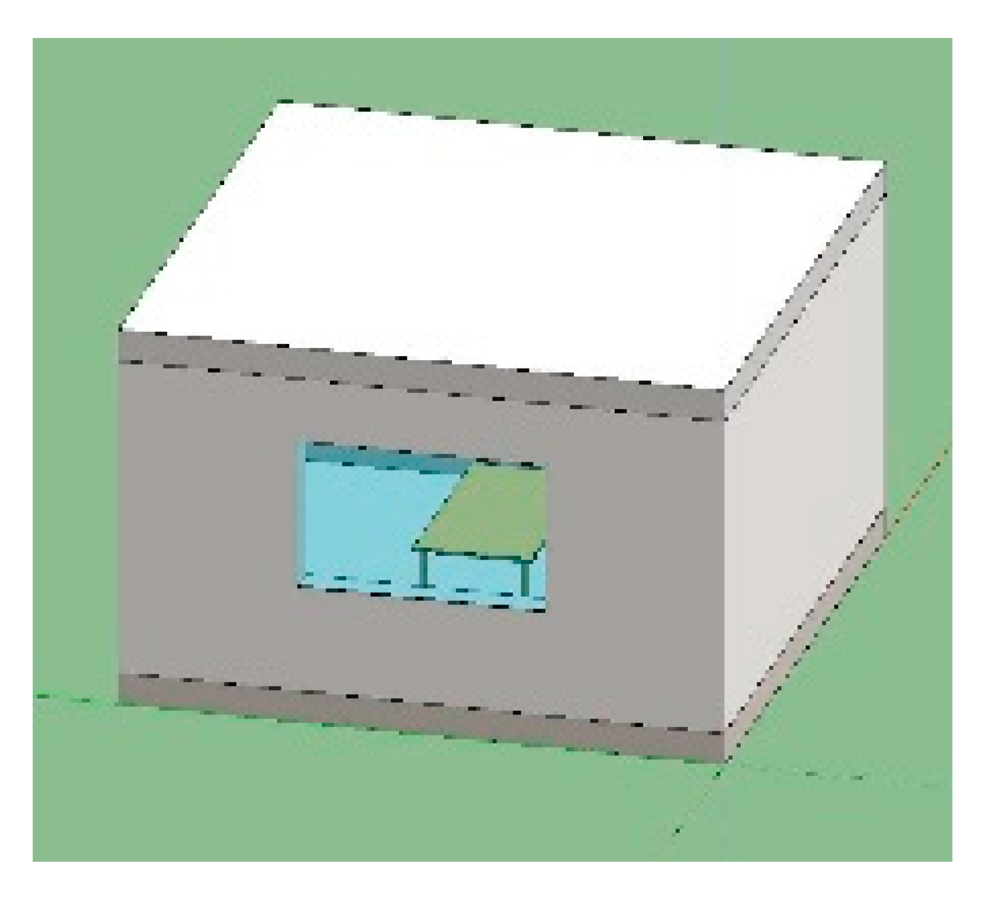
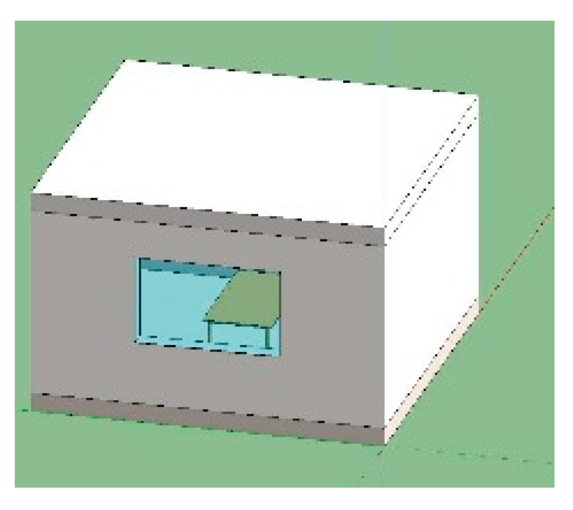
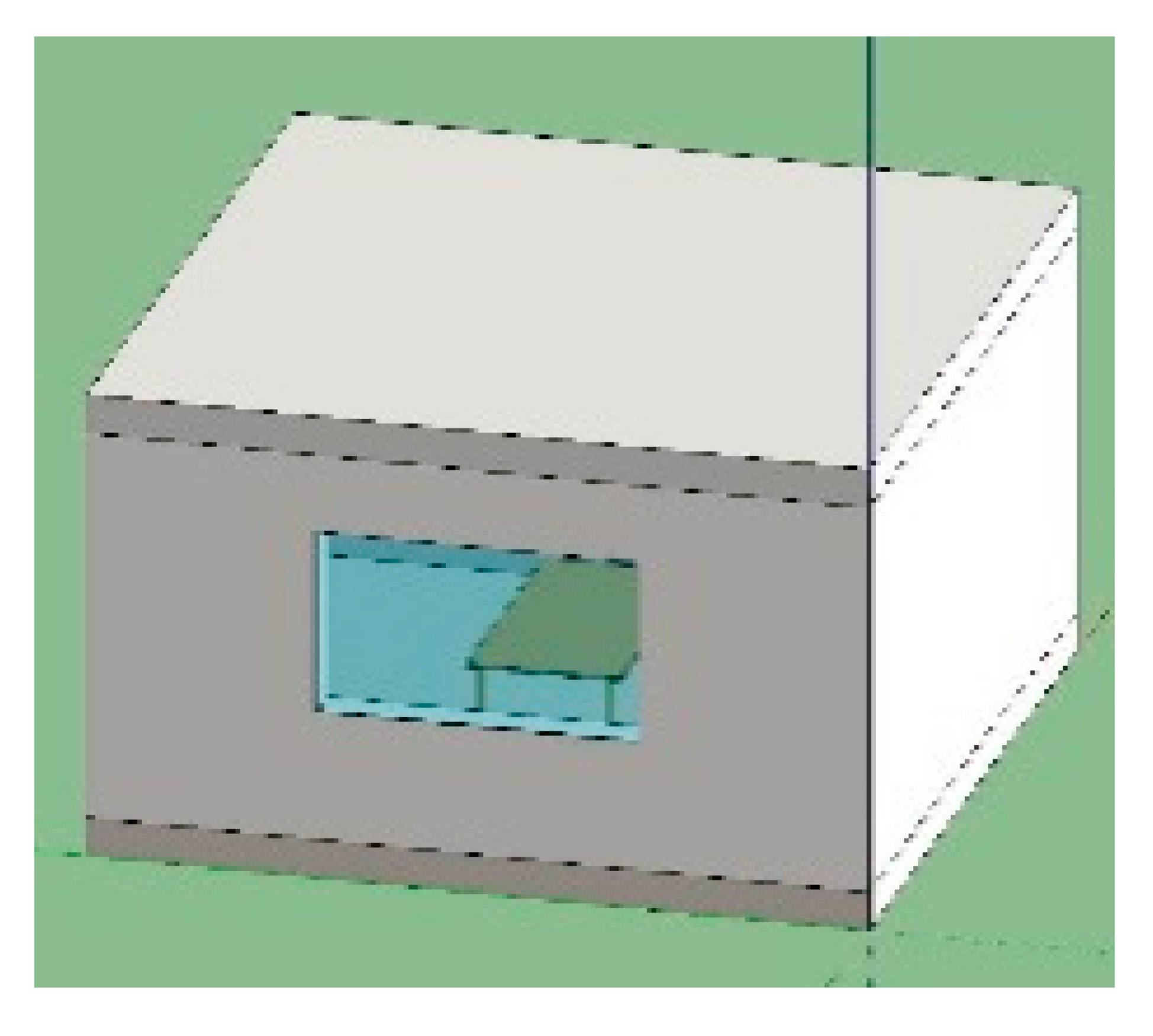
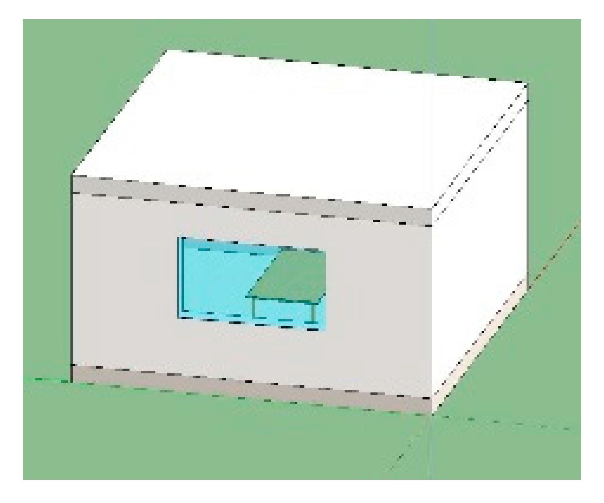
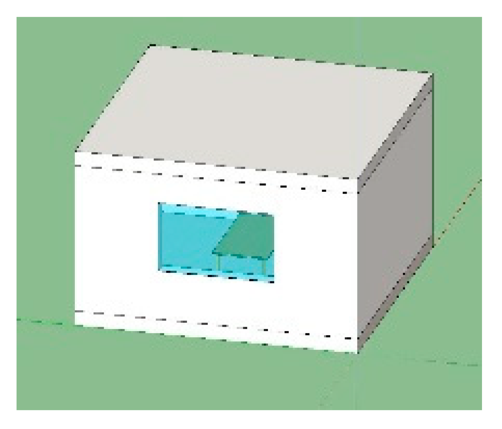
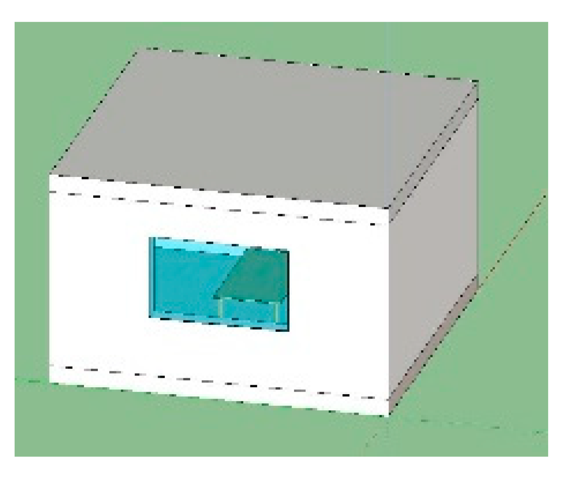
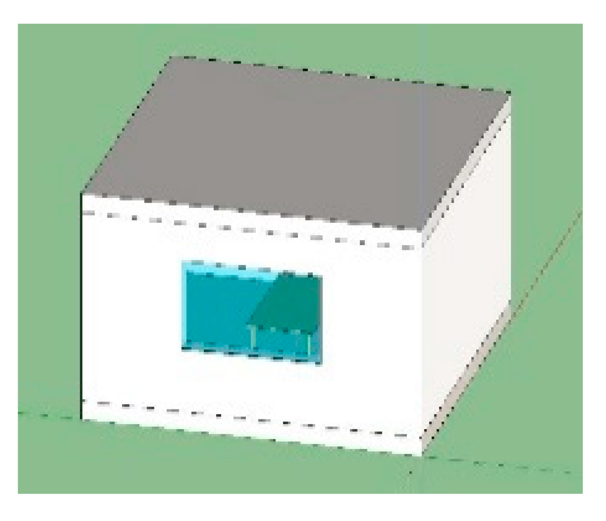
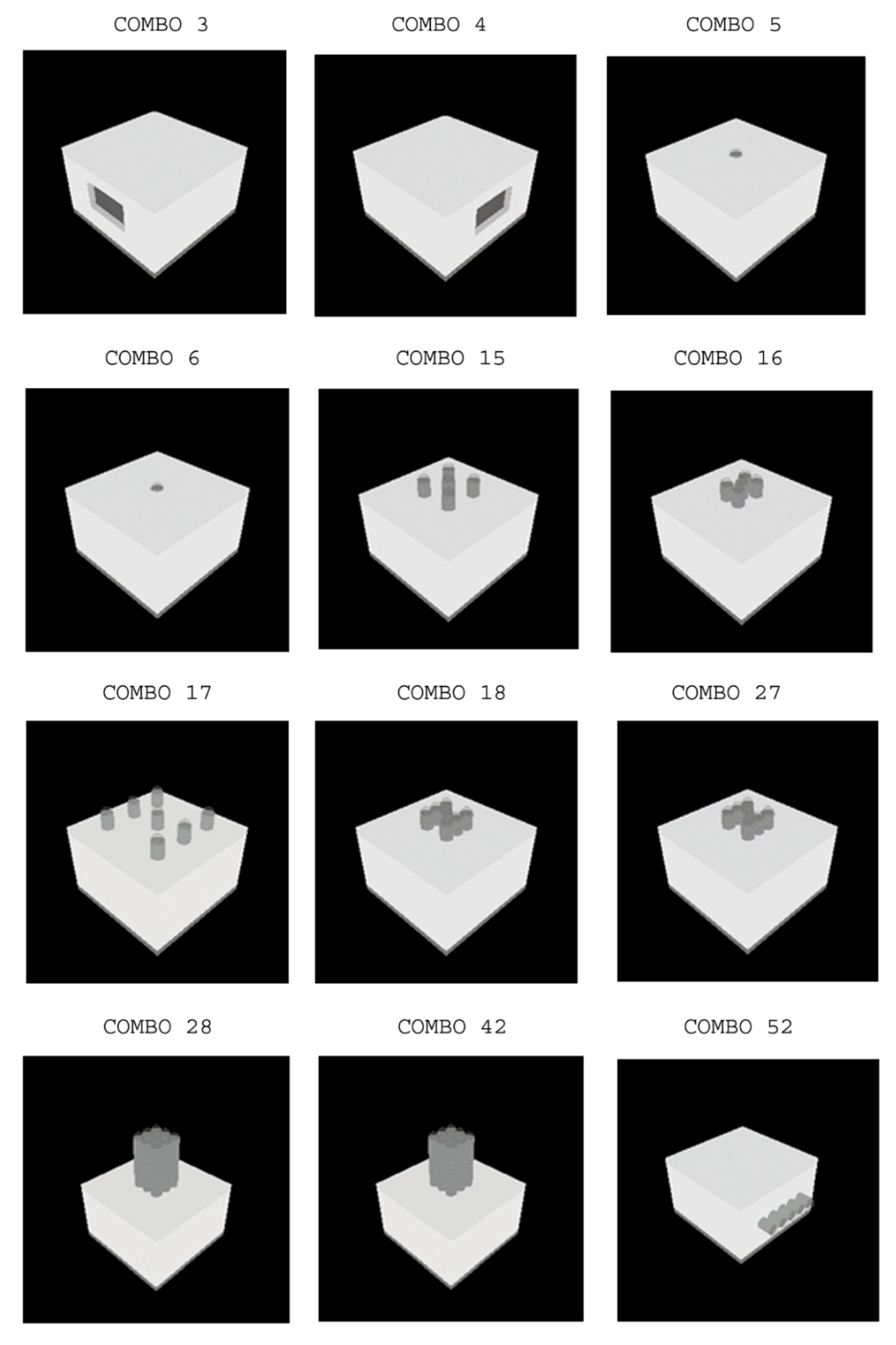
Figure 2 shows some examples of combinations.

3.4. Data Output

As shown in Figure 3, the analyses are carried out for three work areas (whole room, central table, and lateral table). A total number of 81 sensors were considered for the whole room; 15 sensors are positioned on a central table (2 × 1 m), and 15 side sensors are positioned on a lateral table (the table has the same size, and it is positioned near the west wall). The zone is occupied from Monday to Sunday from 8:00 to 20:00. The total time of occupancy of the work place is 4380 h.

4. Results and Discussions

In this section, the results are presented. The following subsection describes the results of the simulations of the room with windows, vertical light pipes, and horizontal light pipes. A study of the different performances of the vertical and horizontal pipes has been carried out by varying the length of the pipes. Furthermore, there is a subsection in which the DA is evaluated for different work areas. In addition, the probability of dazzle, the yearly global illuminance analysis, and the energy analysis are presented at the end of this section.

4.1. DAc and DA of Windows, Vertical Pipes, and Horizontal Pipes

The first step of this study is the evaluation of the DAc and DA for all configurations. The analyses were conducted considering the whole room and for two different dispositions of the table inside the room.

4.1.1. Reference Room with Windows

Table 4 shows the minimum, maximum, average, and standard deviation of the DAc and DA for two different lighting levels: 500 and 200 lx. These values have been suggested by the technical standard [51] for the most common tasks. The values are reported considering all the window orientations for the whole room.
High DAc and DA average values lead to reducing the integration with the artificial lighting, while low values for the DAc and DA standard deviations guarantee a uniform distribution of daylight.
In the following tables, all the values are highlighted with a scale of colors, the best values of each column are presented in green, and the worst ones are presented in red.
Analyzing the whole room, the west orientation (Combo 3) permits reaching both the maximum value of the average and the minimum value of standard deviation for both DAc and DA, showing the best performances, followed by the south orientation (Combo 4).
Table 5 shows the behaviour of the outdoor and indoor daylight of the west window case within four hours of four different days (each one characteristic of different seasons). It gives an idea of the evolution that the lighting can have during the year.
Table 6 and Table 7 show the minimum, maximum, average, and standard deviation of the DAc and DA for two different lighting levels—500 lx and 200 lx—for the central and lateral positions of table, respectively. The results confirm the previous analysis, the West orientation (Combo 3), followed by the South one (Combo 4), is the best one.

4.1.2. Room with Vertical Pipes

Table A1 (see the Appendix A) shows the minimum, maximum, average, and standard deviation of the DAc and DA for two different lighting levels: 500 lx and 200 lx. The values are reported considering the vertical pipe configurations for the whole room. The table is divided into three groups according to the length of the pipe (L):
-
Combos 5–12 with 0.3-m pipe length;
-
Combos 13–20 with 1-m pipe length;
-
Combos 21–28 with 3-m pipe length.
Starting from the configuration with five pipes, configurations D and G represent a diffused and a grouped distribution of pipes, respectively. As in the previous cases, the best values are presented in green, and the worst are presented in red. As expected, the best configurations are those with the lowest pipe length and the highest number of pipes. The best configurations, in terms of high DAc and DA average value and the lowest value of DAc and DA standard deviations, are Combos 11, 12, 17, and 19, where 11 and 19 show the highest values of the average and 12 and 17 show the lowest values of the standard deviations for both DAc and DA. Table A2 and Table A3 (see the Appendix A) show the minimum, maximum, average, and standard deviation of the DAc and DA for two different lighting levels: 500 lx and 200 lx for the central and lateral table configurations, respectively. The results confirm the previous analysis; Combos 11, 12, 17, and 19 show the best performances.

4.1.3. Room with Horizontal Pipes

Table A4, Table A5 and Table A6 show the results for the light pipe configurations in the horizontal position. The analyses of DAc and DA show that good results are obtained with horizontal pipes placed on the south and then on the west side. The position on the south side prevails analyzing the whole room, while the position on the west side prevails with the lateral position of the table on the same side. In detail, positioning the pipes at a lower height from the floor improved their performances.

4.2. DAc and DA Trends for Different Vertical Pipe Lengths

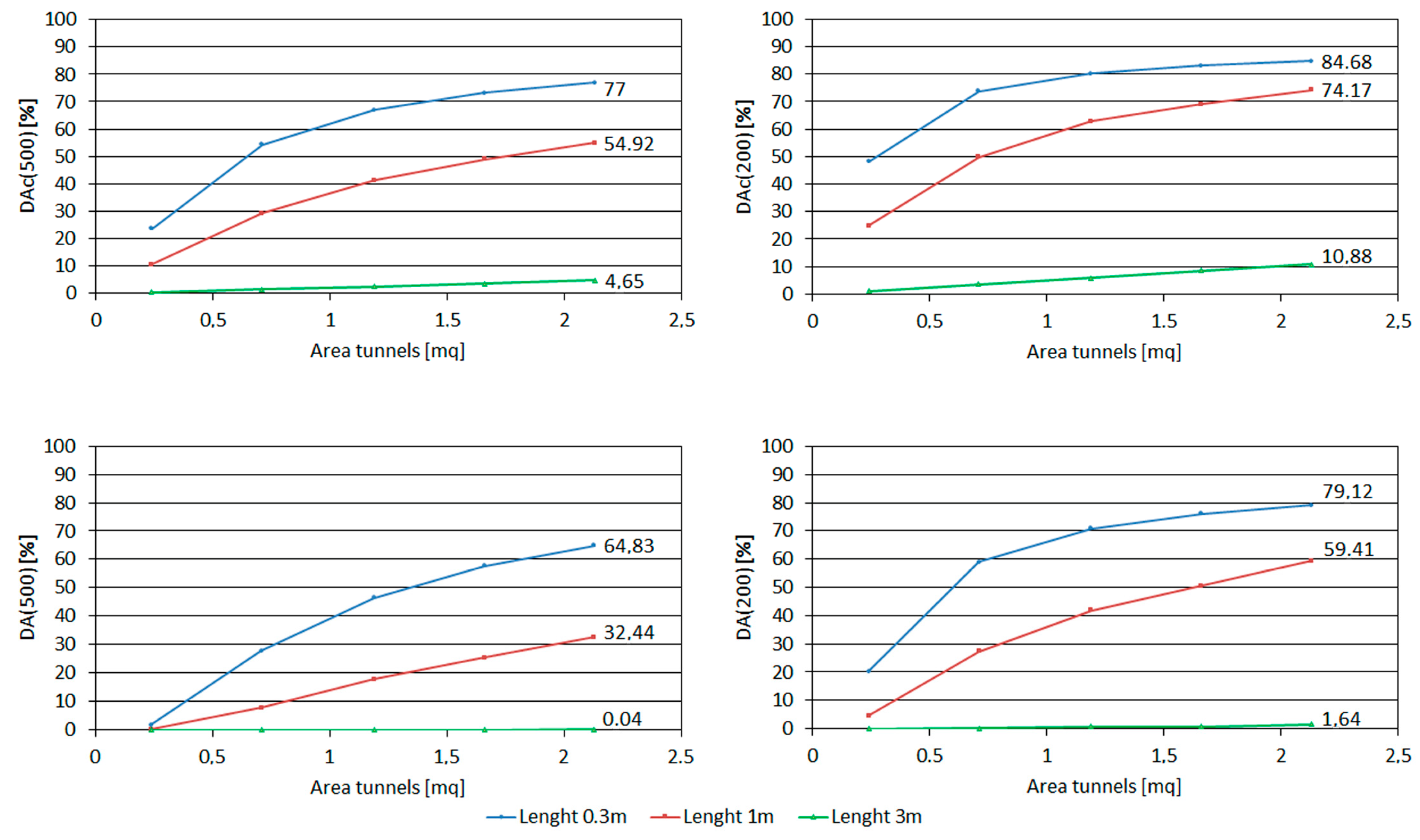
The values of DAc and DA are strongly influenced by the number of pipes and their length. Figure 4 shows the trends of DAc and DA averages of the whole room configuration, for lighting levels of 500 lx and 200 lx. On the horizontal axis, the total cross-sectional area of the pipes is shown, while on the vertical axis, there are the percentage values of the DAc. The three curves display the trend for the different analyzed lengths (0.3, 1, and 3 m).
It can be observed that the maximum values of DAc and DA, for illuminance level of 500 lx, are reached for an area of about 2.13 m2, corresponding to nine pipes. Of course, maximum performance is achieved with pipes that are 0.3 m in length. The decay of performance is notable by a length of 3 m, which guarantee values of only 4.65% and 0.04% for DAc and DA, respectively.
For an illuminance level equal to 200 lx, the pipes reach a maximum value of DAc equal to 84.68% for 0.3-m pipes and 10.88% for 3-m pipes, confirming a drastic reduction of their performances.
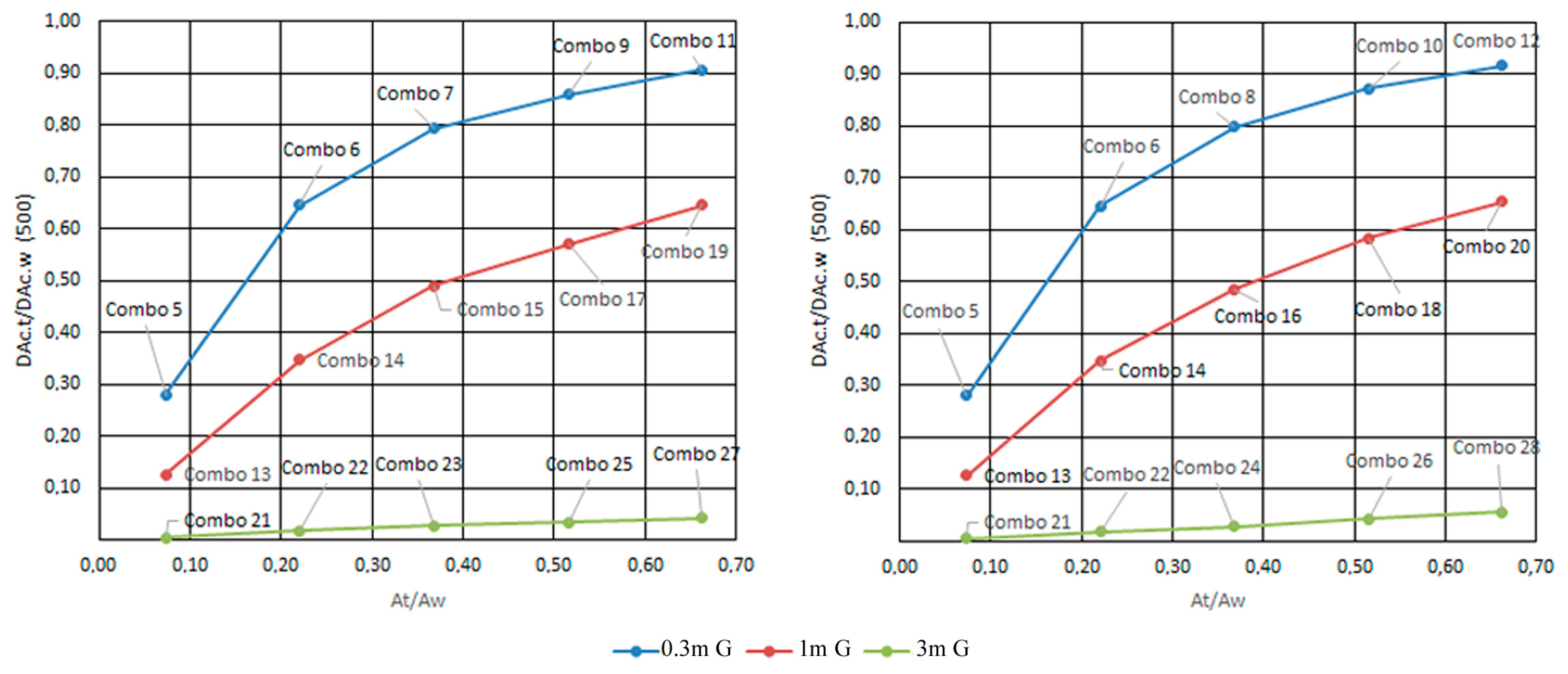
In Figure 5, for the whole room, a comparison between the reference room with a window placed on the west side (Combo 3) and the configurations with vertical pipes, by varying number and lengths of them, are shown. The choice of Combo 3 was determined because it showed the best results in comparison with the other window orientations.
On the horizontal axis, there is a ratio between the transversal area of the vertical pipes and the window area (At/Aw), while on the vertical axis, there is a ratio between the corresponding values of the DAc.
It is interesting to note that, with a surface ratio close to 0.7 and a length of 0.3 m, the use of pipes allows obtaining a DAc ratio close to one, showing a behavior like that of a simple window.

4.3. DAc and DA Trends for Different Horizontal Pipe Lengths

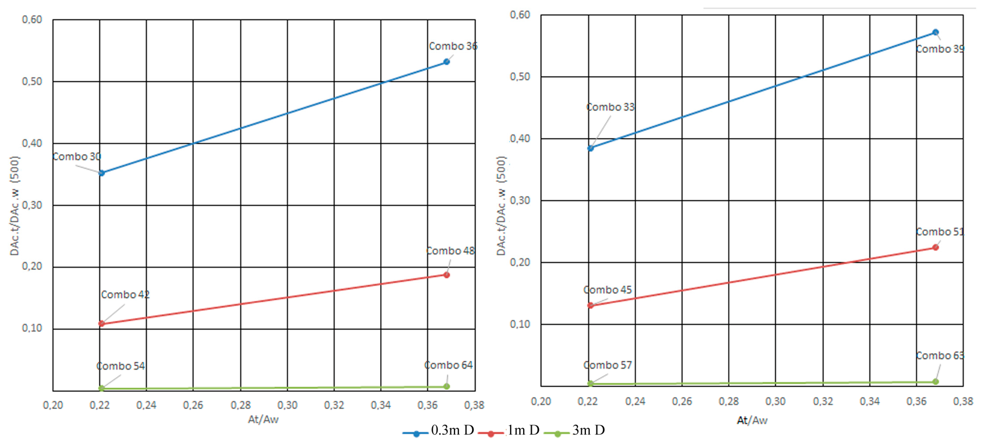
In Figure 6, again for the whole room, the comparison has been done again with the window positioned on the west side (Combo 3), but with horizontal pipes also placed on the same orientation (west).
Comparing the two graphs in Figure 7, a pipe height of 1.5 m shows the best values for a working plane 0.8 m from the floor.

4.4. DA Evaluation for Different Work Areas

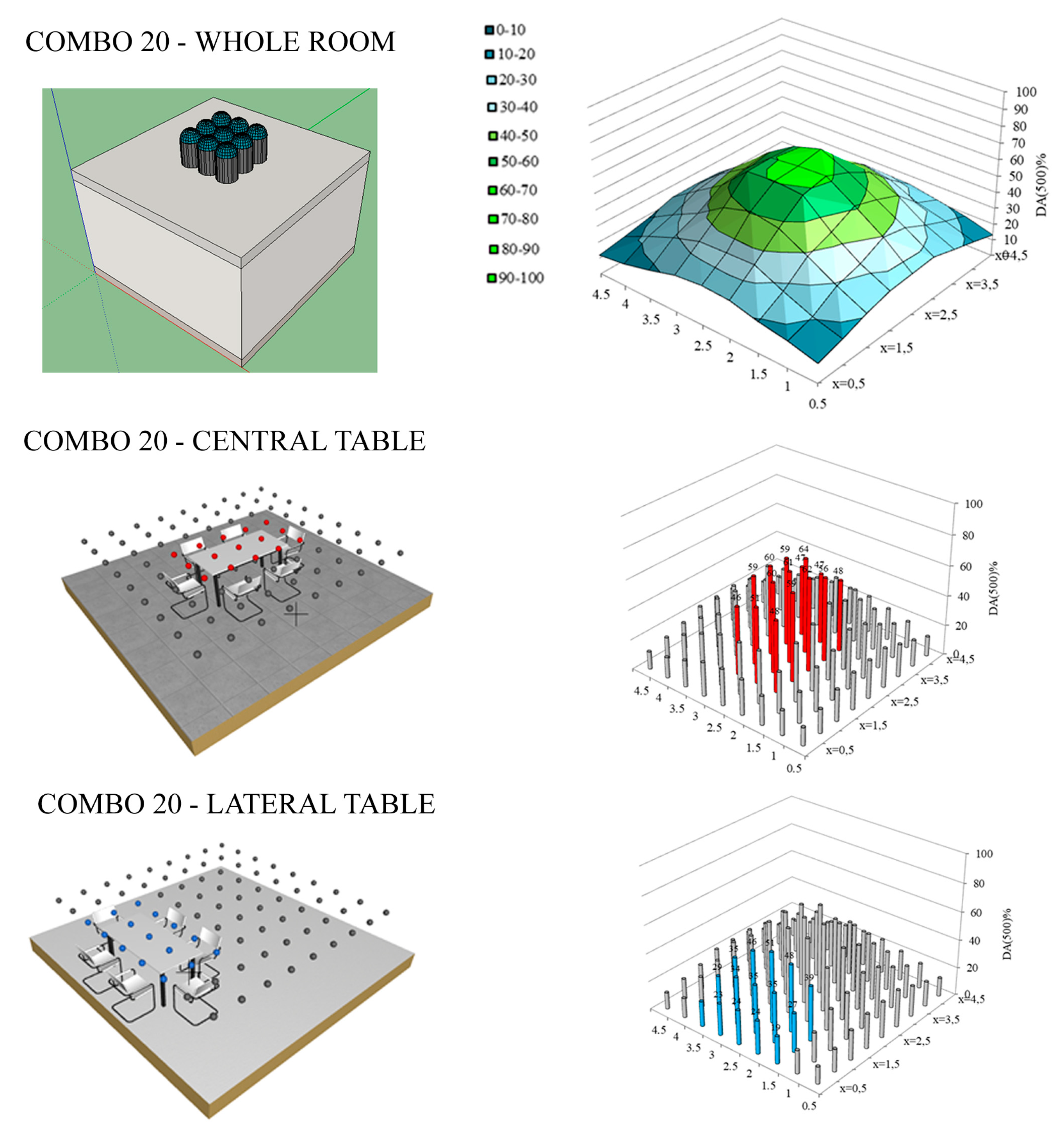
This section estimates the spatial variability of DA for Combo 20, which is characterized by nine pipes in grouped disposition (Typology G) and with a length of 1 m. The work plan chosen is 0.8 m from the floor. As shown in Figure 7, three cases were analyzed:
(1)
Extended work area for the whole room;
(2)
Work area on a centrally positioned table with dimensions of 2 × 1 m;
(3)
Work area on the same table but positioned laterally near the west wall.
The first diagram shows the DA (500) spatial trend; the graph shape is due to the arrangement of the pipes, so greater levels of illuminance are achieved in the central part of the room. The minimum value is 11.80%, the maximum value is about 63.58%, the average value is 32.44%, and the standard deviation 14.22. The second diagram shows the case with the work area on a centrally positioned table. About the central table, the sensor values on the table are shown in red. The minimum value is 46%, the maximum value is 64.00%, the average value is 55%, and the standard deviation is 6.23. The last diagram shows the case with the table positioned laterally near the west wall. The sensor values on the table are shown in blue. The minimum value is 17.88%, the maximum value is 50.62%, the average value is 32.39%, and the standard deviation is 9.9.
Analyzing the results, it is possible to note that the best configuration is with the table placed centrally; the highest DA (500) levels are reached, and the standard deviation has also reached the lowest value of the three cases, ensuring better uniformity.
This short example makes it possible to understand the importance of defining a specific region for the achievement of a certain level of illuminance. This aspect is amplified for environments with a shape (for example elongated shape) where it is necessary to achieve precise values of illuminance in order to perform specific tasks.

4.5. Probability of Dazzle—UDI (2000)

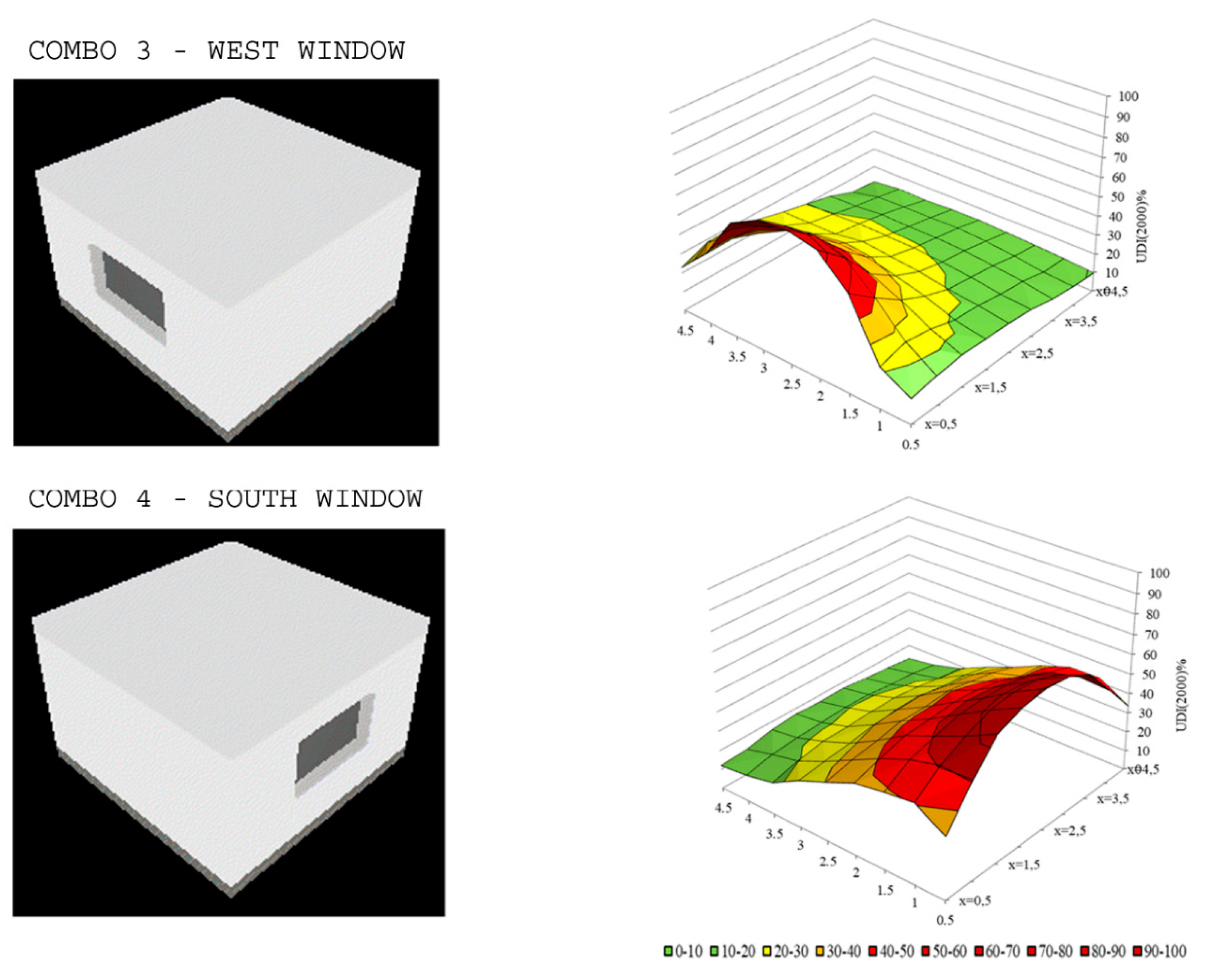
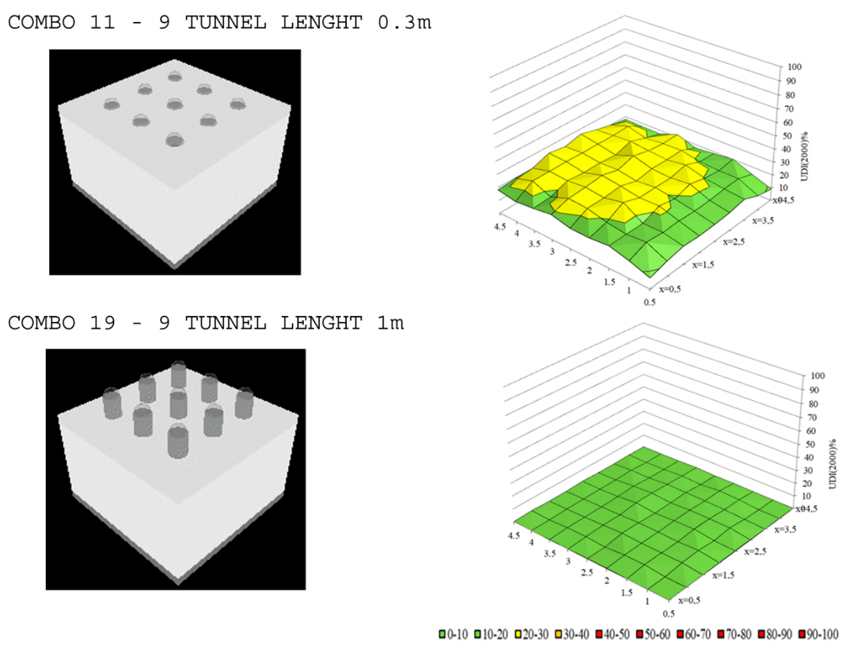
The analyses carried out up to this point have been quantitative; the achievement of high daylight values is not always linked to the achievement of high standards of visual comfort. Excess light can also be a problem; it can generate glare and excessive thermal load, especially during the summer and the central hours of the day. The qualitative study turns out to be of fundamental importance for correct planning. The parameter UDI (2000) defines the percentage of time in which the level of 2000 lx is reached or exceeded, with a consequent potential dazzle risk. Two simulations with windows facing west (Combo 3) and south (Combo 4), and two with nine vertical pipes (length 0.3 m for Combo 11 and 1 m for Combo 19) will be compared.
The surface diagrams shown in Figure 8 express the different percentages achieved through a chromatic map for Combos 3 and 4, with the windows on the west and south, respectively. The medium dazzle risk is defined in yellow, while the values in green are lower than 20%, corresponding to a low risk.
It should be noted that all the configurations with windows have values of UDI (2000) higher than 50%. The only difference is related to the orientation, so the color map will take different positions depending on this orientation.
The positioning of the window to the south (Combo 4) is the worst condition, since most of the environment is exposed to medium and high dazzle risk, and only the area to the north has levels below 20%. Figure 9 represents the configurations with nine pipes (lengths 0.3 m and 1 m). The configuration with nine pipes (length 0.3 m) is considerably better than those with windows, as the UDI (2000) reaches maximum values 20–30%, there is a medium-low risk, and no area of the environment is exposed to a high probability of dazzle. By increasing the length of the pipes up to one meter, the risk is practically null; the whole room surface is colored green.

4.6. Global Illuminance Analysis during the Year

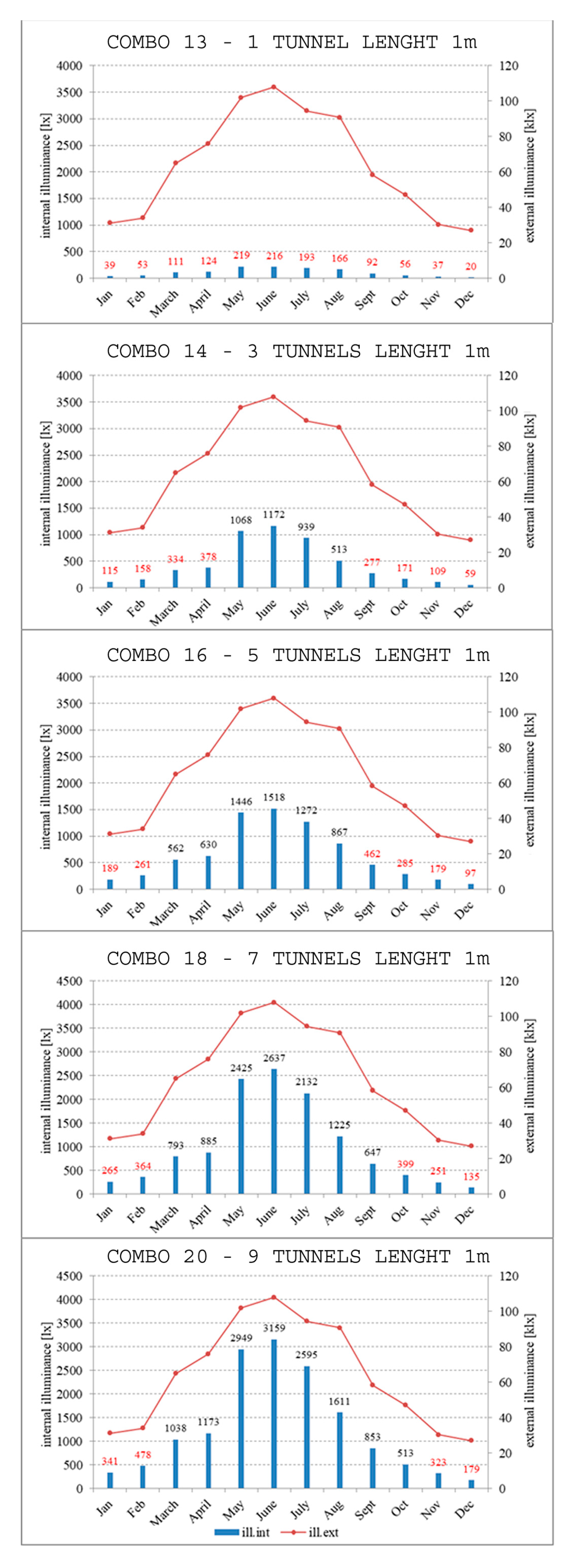
The last part of this research consists of evaluating the overall performance of light pipes (only 1 m long) during the whole year. The blue histograms in Figure 10, for the whole room, represent the internal average illuminance assessed on the 21st of each month at 13:00, which is represented on the left vertical axis in lux. The histogram value is reported in red if it is lower than 500 lx, and in black if it is higher. On the right vertical axis, the outdoor illuminance values are shown in klx.
As shown with Combo 13, the levels reached by a single pipe are not enough; all the values (in red) are below the 500 lx threshold.
The performances of light pipes are strongly influenced by the amount of solar radiation, as can be seen from the trend of the diagrams; the highest levels are obtained during summer when the level of outdoor illuminance reaches its peak. During winter and autumn, it is difficult to reach satisfactory illuminance levels. A single pipe of 0.55 m in diameter and 1 m in length is not enough; the trend increases with the number of pipes up to a maximum of 3159 lx with nine pipes.
It is possible to calculate the daylight penetration factor (DPF), which is equal to the ratio between the indoor and outdoor lighting level and evaluate the potential of the devices during the year. Considering the case with nine pipes, the following results are obtained, with a recommended value of 2%, as shown in Table 8. The DPF higher than 2% is highlighted in red.

4.7. Energy Analysis

As before said, the daylighting has many advantages such as energy savings. Moreover, it must be reminded that the light pipes can provide daylight also in spaces where it is not possible to install traditional windows. In order to demonstrate this, an energy analysis has been carried out. Using the DA and the DAc, the potential energy savings by applying 1-m and 3-m pipes have been calculated. The DA has been used to identify the moment when it should be necessary to switch on the artificial lighting; therefore, in this case, it has been supposed that the lighting system has an on–off control system. The DAc has been used with a lighting system with dimming control. The analysis has been performed including 50 W of absorbed power of the lighting system and 4380 h/y of occupancy schedules. Moreover, in order to perform this analysis, only the sensors on the workplane have been considered. In Table 9 and Table 10, the calculation of the nine pipes of 1-m case are shown as an example. The tables show the analysis conducted for 12 sensors; the first one reports the energy savings estimation using the DA values, and the second reports the energy savings estimation using the DAc values.
Obviously, it is possible to see that the energy savings are higher by using the DAc.
Table 11 shows the estimation of the energy savings carried out for 1-m long pipe configurations. It is possible to see that it is possible to obtain good energy savings mainly for the combinations with five and nine pipes.
The table shows that it is possible to achieve high energy savings mainly for the combinations with five and nine light pipes.

5. Conclusions

The present paper is concerned with the lighting study of a test room located in southern Italy, in the city of Lecce. Using the DAYSIM simulation software, daylight conditions were compared for different light vertical pipe configurations. The length and layout of the pipes have been varied: lengths were 0.3 m, 1 m, and 3 m, and the number of pipes was either 1, 3, 5, 7, or 9. For configurations with 5, 7, and 9 pipes, the distribution was investigated, assuming grouped and diffused configurations.
Pipes in horizontal position have been investigated by varying the number of pipes from three to five, as well as the orientation. The results were compared with those of a test room in which there was a window with a surface of 1/8 of the floor surface and the same pipe orientation.
The parameters analyzed were: DA, DAc, and UDI (2000). The DA and DAc were calculated for two different lighting levels equal to 200 lx and 500 lx as a function of possible different uses.
The results showed a strong correlation between the percentage levels of DA and DAc with the length and number of pipes. The best performances were obtained with nine pipes with a length of 0.3 m. It can be noticed that the illuminance levels decrease, drastically increasing the length; in the cases with 3-m pipes, the percentages of these two parameters are not enough for good vision. Therefore, the simulated model is strongly influenced by the aspect ratio (R = diameter/length).
The spatial distribution of the DA was analyzed, assuming a working area extended to the entire room, and two smaller work areas of the size of a table (2 × 1 m) placed in a central position and in a lateral position, near the west wall.
The second part of the paper is concerned with the study of the UDI (2000) parameter, which is an indicator of potential glare risk. From the comparison with the window simulations, it can be noted that the presence of pipes improves the situation, passing from glare values above 50% for windows facing south, to values below 10% for pipes with a length of 1 m. In this case, the length is beneficial to avoid visual discomfort caused by lighting levels above 2000 lx. No considerations of an energetic nature have been made, but the presence of pipes reduces the risk of entry of excessive thermal energy caused by solar irradiation, especially during summer.
From a global analysis evaluated on the available climatic data, a strong variability of the illuminance levels in the different months of the year has emerged; the best performing period is summer, where the levels of outdoor illuminance are greater.
Light pipes are systems that allow making the most of daylight and make it possible to illuminate environments without openings. The excessive variability of the levels of light reached, under different sky conditions, does not permit their use in an autonomous way. These devices need to be placed side by side with artificial lighting systems to guarantee sufficient light levels in the absence of daylight.
Research has shown that proper design is essential to achieve high levels of visual comfort. There are no totally reliable numerical models due to the complexity of the phenomenon. Many results are influenced by the sky conditions and the characteristics of the pipes.
The objective of this study is to provide technicians and designers with a simple and versatile method to analyze the performances of light pipes, and the results are very complex if considered with a high level of detail.
The method presented can be used not only in the design phase but can also be useful to address an initial economic evaluation in the choice of light pipes considering the number of pipes, the different geometric characteristics, and their disposition within the space considered.
In order to investigate the effectiveness of the data obtained, validation with experimental analyses is expected among the future developments of this study.
Author Contributions

Conceptualization, P.M.C.; Methodology, C.B., M.B. and P.M.C.; Software, M.B.; Validation, C.B. and M.B.; Formal Analysis, C.B. and M.B.; Investigation, C.B., M.B. and P.M.C.; Resources, C.B., M.B. and P.M.C.; Data Curation, C.B. and M.B.; Writing—Original Draft Preparation, C.B.; Writing—Review & Editing, C.B., M.B. and P.M.C.; Visualization, P.M.C.; Supervision, C.B., M.B. and P.M.C.

Funding

This research received no external funding.

Acknowledgments

The authors thank Lorenzo Merenda for his support regarding the calculations.

Conflicts of Interest

The authors declare no conflict of interest.

Nomenclature

ALEAnnual Light Exposure
ASEAnnual Sunlight Exposure
DADaylight Autonomy
DAcContinuous Daylight Autonomy
DAc.tContinuous Daylight Autonomy of tunnel
DAc.wContinuous Daylight Autonomy of window
DPFDaylight Penetration Factor
DSPDaylight Saturation Percentage
LLength of light pipes
LxLux
NNumber of light pipes
SdaSpatial Daylight Autonomy
TOTTotal
UDIUseful Daylight Illuminance

Appendix A

Table A1. DAc and DA vertical pipes for the whole room.
WHOLE ROOM
ComboLTypNAtot TDAc.t (500)DAc.t (200)DAt (500)DAt (200)
m m2min %max %average %st. devmin %max %average %st. devmin %max %average %st. devmin %max %average %st. dev
50.3-10.2411.2737.2923.506.5327.9764.9048.188.610.009.611.482.702.2639.2520.388.66
60.3-30.7137.3267.9354.287.8761.3081.2173.835.169.4743.7027.628.4637.4972.1058.939.39
70.3D51.1952.9375.0766.725.0672.6183.9780.192.4028.0460.5045.178.0457.4077.9570.824.35
80.3G51.1953.5576.8067.065.9373.0684.7580.272.8128.7464.0046.379.4157.7279.5070.945.20
90.3D71.6666.3975.3872.242.0080.0984.0382.580.8843.7961.5555.314.1270.4678.0175.291.61
100.3G71.6661.5280.1373.254.2477.8586.1783.011.9337.5870.3257.647.9966.3581.6476.133.60
110.3D92.1371.6578.7176.231.5382.2585.4184.330.6954.1368.2963.522.9774.7780.6478.651.34
120.3G92.1368.9582.6677.003.3481.0687.3584.681.5548.6175.3064.836.1672.1983.5879.122.70
131-10.242.6725.9510.505.796.6852.5424.7911.980.000.620.010.080.0022.904.556.46
141-30.7110.8755.8629.1111.6024.8476.6649.9313.890.0027.037.627.316.3063.5827.3014.55
151D51.1919.1560.2141.1410.5236.6177.9562.8410.132.6734.3816.958.4014.6866.6041.8414.07
161G51.1920.5965.7940.7212.4837.9080.2061.3311.793.2940.9617.5810.0516.2870.5040.9016.18
171D71.6637.4156.0146.964.8259.3975.6469.134.1413.8429.3821.424.2635.2162.3549.527.44
181G71.6627.4672.7348.9912.1047.3882.8668.509.307.4755.5725.3711.9023.2675.7550.6115.06
191D92.1343.0760.7254.274.3765.6677.5074.172.6819.0635.8728.764.5643.0166.1259.415.54
201G92.1332.7976.2554.9212.3153.6084.3472.648.1811.8063.5832.4414.2229.7378.8157.2414.27
213-10.240.033.100.400.640.077.761.001.600.000.000.000.000.000.000.000.00
223-30.710.2215.811.432.260.5437.803.555.500.000.000.000.000.007.970.100.88
233D51.190.398.822.261.960.9722.055.654.900.000.000.000.000.000.000.660.02
243G51.190.3813.322.343.020.9631.105.747.220.000.000.000.000.007.170.381.38
253D71.660.906.262.801.262.2515.666.993.160.000.000.000.000.000.000.000.00
263G71.660.5715.943.493.941.4335.798.489.190.000.000.000.000.009.730.782.09
273D92.131.885.993.541.014.6914.998.852.520.000.000.000.000.000.000.000.00
283G92.130.7523.144.655.471.8846.5910.8811.860.002.420.040.280.0017.761.643.96
Table A2. DAc and DA vertical pipes for the central table configuration.
CENTRAL TABLE
ComboLTypNAtot TDAc.t (500)DAc.t (200)DAt (500)DAt (200)
m m2min %max %average %st. devmin %max %average %st. devmin %max %average %st. devmin %max %average %st. dev
50.3-10.2426.4037.2932.243.6151.4464.9058.993.860.009.613.833.1123.2239.2531.624.40
60.3-30.7162.0767.9364.631.8778.9581.2179.840.7934.2043.7038.752.6268.4072.1069.971.10
70.3D51.1970.7375.0773.321.3982.1683.9783.190.6150.5760.5056.853.0974.3677.9576.361.19
80.3G51.1972.9076.8074.911.1183.0384.7583.880.4955.7364.0060.232.4075.9479.5077.731.01
90.3D71.6672.6075.3873.900.7682.7084.0383.320.3755.6661.5558.741.5475.5378.0176.580.70
100.3G71.6676.9580.1378.460.9684.7186.1785.390.4564.7370.3267.661.8079.3881.6480.530.66
110.3D92.1377.2078.7177.990.3884.8085.4185.120.1665.1468.2966.850.8379.6380.6480.180.26
120.3G92.1379.9482.6681.240.7486.0687.3586.670.3570.1675.3072.301.4381.4883.5882.410.57
131-10.2413.7825.9520.043.8733.4452.5443.986.020.000.620.080.177.3522.9015.574.96
141-30.7141.4155.8647.083.9565.1476.6670.283.2614.8927.0319.513.5440.9863.5850.616.35
151D51.1950.0960.2156.213.4072.1077.9575.731.8323.4734.3829.773.7155.2566.6062.433.62
161G51.1952.4665.7959.714.2373.5780.2077.402.0625.8940.9633.824.6958.1170.5065.603.74
171D71.6646.3954.4150.562.3169.1274.8671.911.8320.6627.9024.971.9748.7260.6654.913.67
181G71.6660.5572.7366.364.0177.7882.8680.151.7434.5755.5743.726.7166.6275.7570.733.04
191D92.1354.9360.7259.171.4274.5977.5076.880.7729.9135.8733.941.3660.6866.1264.911.36
201G92.1368.4076.2572.372.8480.9384.3482.691.2545.7163.5855.096.2371.9978.8175.402.53
213-10.240.353.101.341.020.877.763.352.560.000.000.000.000.000.000.000.00
223-30.711.4315.814.913.433.5837.8012.168.220.000.000.000.000.007.970.541.98
233D51.192.668.825.121.476.6622.0512.803.660.000.000.000.000.000.660.090.20
243G51.194.4613.327.902.9911.1531.1019.206.740.000.000.000.000.007.172.072.60
253D71.661.325.062.351.003.3112.645.882.500.000.000.000.000.000.000.000.00
263G71.663.3115.949.924.018.2635.7923.508.720.000.000.000.000.009.733.723.43
273D92.132.635.943.690.976.5714.859.222.430.000.000.000.000.000.000.000.00
283G92.136.5523.1414.255.3016.2746.5931.7910.100.002.420.230.610.8417.768.055.67
Table A3. DAc and DA vertical pipes for the lateral table configuration.
LATERAL TABLE
ComboLTypNAtot TDAc.t (500)DAc.t (200)DAt (500)DAt (200)
m m2min %max %average %st. dev.min %max %average %st. dev.min %max %average %st. devmin %max %average %st. dev
50.3-10.2416.1333.3523.414.7039.0360.5448.905.730.005.210.811.548.9334.2020.806.64
60.3-30.7143.8665.0956.135.4167.3380.0975.323.1914.9139.1629.656.0046.2870.2361.486.11
70.3D51.1961.3972.0067.263.1978.0882.5580.601.3936.6054.1645.075.2266.6475.3071.522.68
80.3G51.1963.1274.2268.783.5078.4683.5581.211.5138.7459.0048.176.3467.5876.9972.702.87
90.3D71.6668.7573.6871.741.4781.0583.1982.370.6548.2058.4254.252.9472.6576.4674.981.09
100.3G71.6668.7677.6174.012.4881.1885.0083.361.1147.9266.1058.765.0373.1179.9376.871.98
110.3D92.1374.7278.3076.631.1583.6085.2784.510.5460.7367.4964.292.1677.4080.3978.961.03
120.3G92.1373.6480.7577.722.0683.1286.4485.010.9658.4271.4466.053.8276.4282.0879.731.69
131-10.245.6116.419.873.4314.0238.7624.167.870.000.000.000.000.0010.873.063.78
141-30.7118.0445.3029.658.2135.8869.0951.3510.160.4117.997.325.1913.5247.4927.409.95
151D51.1930.8251.5741.567.0352.7373.5964.257.068.8424.2716.425.5228.7257.8142.479.91
161G51.1930.0356.9342.338.4251.0176.0664.028.058.7731.7618.166.9827.0863.1342.9411.49
171D71.6637.4151.3544.774.4059.3972.6767.054.1114.4725.1819.823.5935.2156.6746.006.86
181G71.6637.7362.5949.578.8959.6478.5569.646.7814.2537.4925.338.0635.5967.9051.6412.00
191D92.1350.9559.4755.183.0172.2177.1974.811.6523.7933.9729.523.4555.3965.3460.783.37
201G92.1341.3370.4256.129.2363.4581.8474.115.9117.8850.6232.399.9040.1673.7959.5010.96
213-10.240.090.520.210.120.211.300.530.300.000.000.000.000.000.000.000.00
223-30.710.342.450.890.660.866.122.211.660.000.000.000.000.000.000.000.00
233D51.190.725.762.311.811.8014.405.784.520.000.000.000.000.000.000.000.00
243G51.190.615.431.861.621.5313.574.644.050.000.000.000.000.000.000.000.00
253D71.660.903.571.710.812.258.924.272.020.000.000.000.000.000.000.000.00
263G71.660.857.192.501.972.1317.986.254.920.000.000.000.000.000.000.000.00
273D92.132.424.833.430.756.0412.068.581.870.000.000.000.000.000.000.000.00
283G92.131.1310.253.693.012.8324.389.137.320.000.000.000.000.004.430.491.17
Table A4. DAc and DA horizontal pipes for the whole room.
WHOLE ROOM
ComboLNdOr.Atot TDAc.t (500)DAc.t (200)DAt (500)DAt (200)
m m m2min %max %average %st. dev. min %max %average %st. dev.min %max %average %st. dev.min %max %average %st. dev.
290.332.5East0.7115.1539.0026.985.9935.5565.9651.727.520.0012.693.463.456.6440.7322.458.01
320.331.5East0.7113.0959.6429.4312.8932.0478.3653.6313.430.0029.866.098.514.9566.3926.5217.85
350.352.5East1.1928.9354.1341.416.0556.4375.5567.454.653.3324.0613.484.8122.1761.3943.5310.01
380.351.5East1.1925.3469.8443.6113.3651.8682.5667.889.410.1846.8715.7813.2119.8274.3845.2817.96
41132.5East0.714.6013.298.081.9911.4931.7919.984.800.001.510.050.280.006.350.921.73
44131.5East0.714.4324.7910.105.5211.0748.8423.5310.820.002.170.150.430.0019.663.575.92
47152.5East1.198.4420.4713.882.9221.1043.4932.405.340.001.800.080.360.0014.776.764.01
50151.5East1.198.3832.7416.907.1720.9558.5936.7110.750.008.291.162.240.0028.429.558.83
53332.5East0.710.140.640.280.070.351.600.690.180.000.000.000.000.000.000.000.00
56331.5East0.710.160.790.350.140.391.990.880.350.000.000.000.000.000.000.000.00
59352.5East1.190.271.110.510.120.692.781.260.310.000.000.000.000.000.000.000.00
62351.5East1.190.341.140.580.170.862.851.460.440.000.000.000.000.000.000.000.00
300.332.5West0.7120.3541.6729.625.4443.2869.6856.026.810.0012.724.363.6112.8144.6125.237.64
330.331.5West0.7117.1062.3032.3713.3540.6081.4158.0113.210.0029.847.419.309.3870.9429.9118.64
360.352.5West1.1933.2856.7644.685.7761.7479.1371.724.406.8024.2714.964.1927.9965.3047.289.89
390.351.5West1.1930.2172.6248.0512.9259.3284.8673.167.930.6649.7018.4813.6626.8078.6550.9717.70
42132.5West0.715.5613.959.122.0213.8933.3422.424.730.003.290.120.620.007.511.222.14
45131.5West0.715.2327.4610.995.7313.0852.9725.5511.000.003.740.230.740.0022.633.846.25
48152.5West1.1910.4722.3315.772.8526.0346.7736.334.870.003.950.190.811.4617.568.854.15
51151.5West1.199.9235.8418.877.4624.8063.1840.5710.640.008.611.422.590.0231.5511.489.35
54332.5West0.710.150.810.310.090.382.030.780.220.000.000.000.000.000.000.000.00
57331.5West0.710.170.940.420.150.422.361.040.380.000.000.000.000.000.000.000.00
60352.5West1.190.282.570.580.250.716.431.460.630.000.000.000.000.000.000.000.00
63351.5West1.190.381.090.700.170.952.731.740.430.000.000.000.000.000.000.000.00
310.332.5South0.7121.4050.2535.357.7347.9371.3961.795.850.0018.725.595.2315.1454.3837.7310.91
340.331.5South0.7118.8867.7437.5515.5044.9780.6362.5710.990.0047.9710.7215.5410.0572.2838.7919.58
370.352.5South1.1937.7164.4852.546.7365.6378.8573.053.145.8243.9023.3810.4743.4968.4057.506.02
400.351.5South1.1933.5274.4653.6312.8963.1783.5973.736.291.1259.5925.4619.7639.5076.9258.7711.63
43132.5South0.715.8415.9310.212.7214.5938.1525.116.370.003.770.140.700.007.311.272.01
46131.5South0.715.6131.8012.457.0214.0159.5529.0513.500.002.260.080.330.0035.055.319.72
49152.5South1.1911.1625.4617.623.7827.8952.9941.146.570.004.020.080.450.1623.409.236.72
52151.5South1.1910.6342.5921.169.6326.5866.8544.5712.430.0010.251.262.740.0047.5315.1916.20
55332.5South0.710.131.350.320.160.323.380.810.410.000.000.000.000.000.000.000.00
58331.5South0.710.160.980.440.150.412.451.090.370.000.000.000.000.000.000.000.00
61352.5South1.190.271.240.560.140.683.091.390.340.000.000.000.000.000.000.000.00
64351.5South1.190.391.520.740.210.973.791.850.520.000.000.000.000.000.000.000.00
Table A5. DAc and DA horizontal pipes for the central table configuration.
CENTRAL TABLE
ComboLNdOr.Atot TDAc.t (500)DAc.t (200)DAt (500)DAt (200)
m m m2min %max %average %st. dev.min %max %average %st. dev.min %max %average %st. dev.min %max %average %st. dev.
290.332.5East0.7121.8538.6031.675.3745.2365.1157.616.490.2312.696.583.5414.4539.7028.237.84
320.331.5East0.7120.4445.6631.098.9343.7872.5956.9910.080.0015.785.875.8313.7052.5828.4113.71
350.352.5East1.1938.3554.1346.165.1965.8975.5571.383.1310.7124.0617.063.9938.5261.3951.537.41
380.351.5East1.1932.8460.3244.859.2059.8979.4670.226.645.3728.1315.447.3829.0667.6548.7713.48
41132.5East0.716.2813.299.692.0715.7131.7923.914.790.000.000.000.000.006.352.032.44
44131.5East0.716.1219.8711.104.1915.3041.9426.198.790.002.170.300.560.0013.063.884.49
47152.5East1.1912.1520.4716.282.8230.0543.4936.954.500.000.000.000.003.6314.779.913.46
50151.5East1.1911.8826.5917.314.8728.6551.6438.197.580.003.040.610.902.4720.4810.376.08
53332.5East0.710.300.640.340.080.761.600.850.200.000.000.000.000.000.000.000.00
56331.5East0.710.270.430.340.050.671.060.850.130.000.000.000.000.000.000.000.00
59352.5East1.190.531.110.630.161.332.781.570.390.000.000.000.000.000.000.000.00
62351.5East1.190.431.140.600.171.072.851.500.420.000.000.000.000.000.000.000.00
300.332.5West0.7126.7641.6734.544.8053.1469.6861.805.750.8412.728.143.4020.5744.6131.567.90
330.331.5West0.7120.7150.5135.199.6945.7277.3462.3710.560.0020.238.637.0815.7558.4933.0513.96
360.352.5West1.1942.2456.7649.634.8570.8379.1375.592.7613.0624.2718.583.7344.0065.3055.617.10
390.351.5West1.1937.8964.4849.588.9466.7882.9775.555.469.1332.7418.858.2535.4674.3255.0313.31
42132.5West0.718.5113.9510.941.7021.2733.3426.983.800.000.000.000.000.007.512.542.74
45131.5West0.716.8618.9211.523.6817.1638.3627.207.760.003.560.430.890.0012.693.674.02
48152.5West1.1914.7722.3318.262.7435.4846.7740.944.030.000.000.000.007.6917.5612.463.78
51151.5West1.1914.8229.6119.494.7635.5154.3042.326.320.006.031.041.805.9123.3612.825.82
54332.5West0.710.330.810.390.110.832.030.970.290.000.000.000.000.000.000.000.00
57331.5West0.710.320.550.420.070.801.381.040.180.000.000.000.000.000.000.000.00
60352.5West1.190.570.870.670.081.432.181.670.190.000.000.000.000.000.000.000.00
63351.5West1.190.611.090.730.151.532.731.820.370.000.000.000.000.000.000.000.00
310.332.5South0.7133.2049.5841.255.0560.8870.5666.442.994.0018.729.424.6736.9253.1345.994.93
340.331.5South0.7126.0551.2637.757.7255.2973.6464.635.460.0018.015.995.8425.0957.3742.279.37
370.352.5South1.1949.4662.4357.223.4471.7177.9175.431.5416.2340.3030.077.0354.2766.8061.903.19
400.351.5South1.1945.4664.0054.396.1569.6178.9774.273.1411.4441.9924.6210.2950.8067.9259.335.86
43132.5South0.719.3915.4612.741.5223.4637.6330.384.180.003.770.741.490.005.592.581.84
46131.5South0.717.6417.8711.903.4019.1042.9929.377.930.000.000.000.000.009.162.303.50
49152.5South1.1916.3524.8820.532.5439.3952.9946.504.000.004.020.281.007.2622.7614.294.83
52151.5South1.1914.7325.9519.663.4336.2854.5045.245.610.000.050.000.013.8124.1612.616.47
55332.5South0.710.291.350.400.250.723.381.000.640.000.000.000.000.000.000.000.00
58331.5South0.710.340.980.480.150.852.451.210.370.000.000.000.000.000.000.000.00
61352.5South1.190.550.830.640.061.382.071.590.150.000.000.000.000.000.000.000.00
64351.5South1.190.581.260.720.161.443.141.800.410.000.000.000.000.000.000.000.00
Table A6. DAc and DA horizontal pipes for the lateral table configuration.
LATERAL TABLE ON WEST SIDE
ComboLNdOr.Atot TDAc.t (500)DAc.t (200)DAt (500)DAt (200)
m m m2min %max %average %st. dev.min %max %average %st. dev.min %max %average %st. dev.min %max %average %st. dev.
290.332.5East0.7118.6725.2521.942.1540.2651.0245.383.180.006.321.461.8412.2619.5715.292.22
320.331.5East0.7114.5723.9818.082.2334.9549.7341.003.510.001.000.130.346.4218.4911.722.54
350.352.5East1.1931.7041.1936.282.9658.3768.6464.253.215.8013.939.112.3225.7344.6635.095.99
380.351.5East1.1927.4433.6231.031.8554.0961.8458.572.100.946.624.041.8621.9931.7127.002.77
41132.5East0.715.638.636.920.8214.0720.2816.691.430.001.510.290.590.002.850.551.09
44131.5East0.714.967.466.240.6412.3918.6515.601.590.000.000.000.000.000.000.000.00
47152.5East1.1910.9413.6112.270.7425.8233.3729.791.980.001.800.230.592.085.823.841.14
50151.5East1.199.8613.7811.470.9824.6532.4028.412.020..000..680..050..170..115..711..601..71
53332..5East0..710..290..400..340..030..731..010..850..070..000..000..000..000..000..000..000..00
56331..5East0..710..240..790..450..170..591..991..120..410..000..000..000..000..000..000..000..00
59352..5East1..190..540..660..590..031..351.651.480.080.000.000.000.000.000.000.000.00
62351.5East1.190.430.930.670.171.092.321.670.420.000.000.000.000.000.000.000.00
300.332.5West0.7128.4241.6735.304.1554.6469.6862.984.723.6512.727.732.9023.7044.6134.086.80
330.331.5West0.7145.6762.3055.005.4373.2381.4178.622.5617.1729.8424.124.3248.6170.9462.777.18
360.352.5West1.1942.7456.7650.124.8469.9579.1375.023.2813.0124.2719.073.9945.7865.3056.226.77
390.351.5West1.1960.5072.6268.044.0981.9284.8683.620.9128.2949.7040.527.3571.4278.6575.882.22
42132.5West0.718.2713.9511.341.9220.6933.3427.774.290.000.000.000.000.007.513.752.76
45131.5West0.7116.1227.4621.583.0837.8652.9744.914.840.003.740.981.459.0022.6315.793.74
48152.5West1.1913.5222.3318.453.0732.0446.7740.344.970.000.000.000.007.2117.5613.123.80
51151.5West1.1924.0335.8431.473.5149.6263.1857.834.220.008.615.762.9118.9031.5526.393.86
54332.5West0.710.200.360.280.050.510.890.710.120.000.000.000.000.000.000.000.00
57331.5West0.710.450.640.540.051.121.611.340.120.000.000.000.000.000.000.000.00
60352.5West1.190.370.590.490.080.911.491.220.210.000.000.000.000.000.000.000.00
63351.5West1.190.630.870.800.071.582.191.990.170.000.000.000.000.000.000.000.00
310.332.5South0.7128.2648.3136.245.6955.2970.4763.033.940.3915.375.774.3224.6152.7239.997.57
340.331.5South0.7122.1055.0534.049.9350.4375.2161.327.650.0024.115.077.0516.6761.3736.1313.90
370.352.5South1.1943.5762.1753.955.9368.5877.6373.732.7911.5139.6125.229.5949.2066.4258.935.39
400.351.5South1.1940.1268.0952.338.5866.7781.0773.224.255.4847.4021.9213.2446.5372.4957.637.73
43132.5South0.717.6114.0510.252.0919.0334.5925.124.940.003.630.240.910.004.501.051.55
46131.5South0.716.4020.9410.103.6316.0048.0424.938.210.000.000.000.000.0014.701.343.65
49152.5South1.1912.6823.4616.932.9531.5750.2340.055.280.000.210.010.051.4419.778.235.12
52151.5South1.1911.5230.8117.935.5528.7559.8841.279.320.000.530.040.130.4635.0210.2910.05
55332.5South0.710.200.360.270.040.500.900.680.100.000.000.000.000.000.000.000.00
58331.5South0.710.230.570.360.100.571.420.900.250.000.000.000.000.000.000.000.00
61352.5South1.190.420.630.520.061.041.571.300.150.000.000.000.000.000.000.000.00
64351.5South1.190.430.870.630.141.072.171.580.340.000.000.000.000.000.000.000.00

References

  1. Ruamsuke, K.; Dhakal, S.; Marpaung, C.O.P. Energy and economic impacts of the global climate change policy on Southeast Asian countries: A general equilibrium analysis. Energy 2015, 81, 446–461. [Google Scholar] [CrossRef]
  2. Bonomolo, M.; Baglivo, C.; Bianco, G.; Congedo, P.M.; Beccali, M. Cost optimal analysis of lighting retrofit scenarios in educational buildings in Italy. Energy Procedia 2017, 126, 171–178. [Google Scholar] [CrossRef]
  3. Congedo, P.M.; D’Agostino, D.; Baglivo, C.; Tornese, G.; Zacà, I. Efficient solutions and cost-optimal analysis for existing school buildings. Energies 2016, 9, 851. [Google Scholar] [CrossRef]
  4. Desideri, U.; Arcioni, L.; Leonardi, D.; Cesaretti, L.; Perugini, P.; Agabitini, E.; Evangelisti, N. Design of a multipurpose “zero energy consumption” building according to European Directive 2010/31/EU: Architectural and technical plants solutions. Energy 2013, 58, 157–167. [Google Scholar] [CrossRef]
  5. Baglivo, C.; Congedo, P.M.; di Cataldo, M.; Coluccia, L.D.; D’Agostino, D. Envelope design optimization by thermal modeling of a building in a warm climate. Energies 2017, 10, 1808. [Google Scholar] [CrossRef]
  6. Malvoni, M.; Baglivo, C.; Congedo, P.M.; Laforgia, D. CFD modelling to evaluate the thermal performances of window frames in accordance with the ISO 10077. Energy 2016, 111, 430–438. [Google Scholar] [CrossRef]
  7. Figueiro, M.G.; Rea, M.S.; Rea, A.C.; Stevens, R.G. Daylight and productivity: A field study. In ACEEE Summer Study; ACEEE: Washington, WA, USA, 2002. [Google Scholar]
  8. Suk, J.Y. Luminance and vertical eye illuminance thresholds for occupants’ visual comfort in daylit office environments. Build. Environ. 2019, 148, 107–115. [Google Scholar] [CrossRef]
  9. Rodriguez, R.G.; Garretón, J.A.Y.; Pattini, A.E. An epidemiological approach to daylight discomfort glare. Build. Environ. 2017, 113, 39–48. [Google Scholar] [CrossRef]
  10. Krüger, E.L.; Tamura, C.; Trento, T.W. Identifying relationships between daylight variables and human preferences in a climate chamber. Sci. Total Environ. 2018, 642, 1292–1302. [Google Scholar] [CrossRef]
  11. van Bommel, W. Visual, biological and emotional aspects of lighting: Recent new findings and their meaning for lighting practice. Leukos 2005, 2, 7–11. [Google Scholar] [CrossRef]
  12. Veitch, J. Principles of healthy lighting: A role for daylight. Int. Daylighting RD&A 2003, 5, 5–6. [Google Scholar]
  13. Boyce, P.; Hunter, C.; Howlett, O. The Benefits of Daylight through Windows; Rensselaer Polytechnic Institute: Troy, NY, USA, 2003. [Google Scholar]
  14. Veitch, J.; Galasiu, A. The Physiological and Psychological Effects of Windows, Daylight, and View at Home; National Research Council of Canada: Ottawa, ON, Canada, 2011; pp. 1–6. [Google Scholar]
  15. Konis, K. A circadian design assist tool to evaluate daylight access in buildings for human biological lighting needs. Sol. Energy 2019, 191, 449–458. [Google Scholar] [CrossRef]
  16. Fakra, A.H.; Miranville, F.; Boyer, H.; Guichard, S. Development of a new model to predict indoor daylighting: Integration in CODYRUN software and validation. Energy Convers. Manag. 2011, 52, 2724–2734. [Google Scholar] [CrossRef]
  17. Zizzo, G.; Beccali, M.; Bonomolo, M.; di Pietra, B.; Ippolito, M.G.; la Cascia, D.; Leone, G.; lo Brano, V.; Monteleone, F. A feasibility study of some DSM enabling solutions in small islands: The case of Lampedusa. Energy 2017, 140, 1030–1046. [Google Scholar] [CrossRef]
  18. Wong, L. A review of daylighting design and implementation in buildings. Renew. Sustain. Energy Rev. 2017, 74, 959–968. [Google Scholar] [CrossRef]
  19. Daysim Software. Available online: https://daysim.ning.com (accessed on 13 May 2019).
  20. Skecthup Sowftare. Available online: https://www.sketchup.com/ (accessed on 13 May 2019).
  21. Oakley, G.; Riffat, S.B.; Shao, L. Daylight performance of lightpipes. Sol. Energy 2000, 69, 89–98. [Google Scholar] [CrossRef]
  22. Brembilla, E.; Pool, D.C.; Hopfe, C.J.; Mardaljevic, J. Evaluation of climate-based daylighting techniques for complex fenestration and shading systems. Energy Build. 2019, 203, 109454. [Google Scholar] [CrossRef]
  23. Mayhoub, M.S.; Carter, D.J. The costs and benefits of using daylight guidance to light office buildings. Build. Environ. 2011, 46, 698–710. [Google Scholar] [CrossRef]
  24. Dulawat, M.S. Study on forced convection type solar tunnel dryer for industrial applications. Agric. Eng. Int. CIGR J. 2012, 14, 75–79. [Google Scholar]
  25. Sharma, L.; Ali, S.F.; Rakshit, D. Performance evaluation of a top lighting light-pipe in buildings and estimating energy saving potential. Energy Build. 2018, 179, 57–72. [Google Scholar] [CrossRef]
  26. lo Verso, V.R.M.; Pellegrino, A.; Serra, V. Light transmission efficiency of daylight guidance systems: An assessment approach based on simulations and measurements in a sun/sky simulator. Sol. Energy 2011, 85, 2789–2801. [Google Scholar] [CrossRef]
  27. Baroncini, C.; Chella, F.; Zazzini, P. Experimental analysis of tubular light pipes performances: Influence of the diffuser on inside distribution of light. In Proceedings of the 5th International Conference on Sustainable Energy Technologies, Vicenza, Italy, 30 August–1 September 2006; pp. 1–6. [Google Scholar]
  28. Kocifaj, M. Efficient tubular light guide with two-component glazing with Lambertian diffuser and clear glass. Appl. Energy 2009, 86, 7–8. [Google Scholar] [CrossRef]
  29. Malet-Damour, B.; Boyer, H.; Fakra, A.H.; Bojic, M. Light pipes performance prediction: Inter model and experimental confrontation on vertical circular light-guides. Energy Procedia 2014, 57, 1977–1986. [Google Scholar] [CrossRef]
  30. Malet-Damour, B.; Guichard, S.; Bigot, D.; Boyer, H. Study of tubular daylight guide systems in buildings: Experimentation, modelling and validation. Energy Build. 2016, 129, 308–321. [Google Scholar] [CrossRef]
  31. Ciugudeanu, C.; Beu, D. Passive tubular daylight guidance system survey. Procedia Technol. 2016, 22, 690–696. [Google Scholar] [CrossRef]
  32. Darula, S.; Kittler, R.; Kocifaj, M. Luminous effectiveness of tubular light-guides in tropics. Appl. Energy 2010, 87, 3460–3466. [Google Scholar] [CrossRef]
  33. Kocifaj, M.; Darula, S.; Kittler, R. HOLIGILM: Hollow light guide interior illumination method—An analytic calculation approach for cylindrical light-tubes. Sol. Energy 2008, 82, 247–259. [Google Scholar] [CrossRef]
  34. Oh, S.J.; Chun, W.; Riffat, S.B.; Jeon, Y.I.; Dutton, S.; Han, H.J. Computational analysis on the enhancement of daylight penetration into dimly lit spaces: Light tube vs. fiber optic dish concentrator. Build. Environ. 2013, 59, 261–274. [Google Scholar] [CrossRef]
  35. Ellis, P.G.; Strand, R.K.; Baumgartner, K.T. Simulation of tubular daylighting devices and daylighting shelves in energy plus. In Proceedings of the IBPSA-USA National Conference, Boulder, CO, USA, 4–6 August 2004; pp. 1–8. [Google Scholar]
  36. Mohelnikova, J. Tubular light guide evaluation. Build. Environ. 2009, 44, 2193–2200. [Google Scholar] [CrossRef]
  37. Samuhatananon, S.; Chirarattananon, S.; Chirarattananon, S.; Chirarattananon, P. An experimental and analytical study of transmission of daylight through circular light pipes. Leukos 2011, 7, 203–219. [Google Scholar] [CrossRef]
  38. Zazzini, P.; Chella, F.; Scarduzio, A. Numerical and experimental analysis of light pipes’ performances: Comparison of the obtained results. In Proceedings of the PLEA 2006—23rd International Conference on Passive and Low Energy Architecture, Geneva, Switzerland, 6–8 September 2006; pp. 219–224. [Google Scholar]
  39. Al-Marwaee, M.; Carter, D. Tubular guidance systems for daylight: Achieved and predicted installation performances. Appl. Energy 2006, 83, 774–788. [Google Scholar] [CrossRef]
  40. Malet-Damour, B.; Boyer, H.; Guichard, S.; Miranville, F. Performance testing of light pipes in real weather conditions for a confrontation with hemera. J. Clean Energy Technol. 2017, 5, 73–76. [Google Scholar] [CrossRef]
  41. Bellia, L.; Pedace, A.; Fragliasso, F. The impact of the software’s choice on dynamic daylight simulations’ results: A comparison between daysim and 3ds max design®. Sol. Energy 2015, 122, 249–263. [Google Scholar] [CrossRef]
  42. Hiyama, K.; Wen, L. Rapid response surface creation method to optimize window geometry using dynamic daylighting simulation and energy simulation. Energy Build. 2015, 107, 417–423. [Google Scholar] [CrossRef]
  43. Cheng, Y.; Gao, M.; Dong, J.; Jia, J.; Zhao, X.; Li, G. Investigation on the daylight and overall energy performance of semi-transparent photovoltaic facades in cold climatic regions of China. Appl. Energy 2018, 232, 517–526. [Google Scholar] [CrossRef]
  44. Gunay, H.B.; O’Brien, W.; Beausoleil-Morrison, I.; Gilani, S. Development and implementation of an adaptive lighting and blinds control algorithm. Build. Environ. 2017, 113, 185–199. [Google Scholar] [CrossRef]
  45. Yun, G.; Kim, K.S. An empirical validation of lighting energy consumption using the integrated simulation method. Energy Build. 2013, 57, 144–154. [Google Scholar] [CrossRef]
  46. Pagliolico, S.L.; Verso, V.R.L.; Bosco, F.; Mollea, C.; la Forgia, C. A novel photo-bioreactor application for microalgae production as a shading system in buildings. Energy Procedia 2017, 111, 151–160. [Google Scholar] [CrossRef] [Green Version]
  47. Handina, A.; Mukarromah, N.; Mangkuto, R.A.; Atmodipoero, R.T. Prediction of daylight availability in a large hall with multiple facades using computer simulation and subjective perception. Procedia Eng. 2017, 170, 313–319. [Google Scholar] [CrossRef]
  48. Longmore, J. Daylighting: A current view. Light Lighting 1975, 68, 113–119. [Google Scholar]
  49. Reinhart, C.F.; Mardaljevic, J.; Rogers, Z. Dynamic daylight performance metrics for sustainable building design. Leukos 2006, 3, 7–31. [Google Scholar] [CrossRef] [Green Version]
  50. Rogers, Z.; Goldman, D. Daylighting Metric Development Using Daylight Autonomy Calculations in the Sensor Placement Optimization Tool; Architectural Energy Corporation: Boulder, CO, USA, 2006; Available online: http://www.archenergy.com/SPOT/SPOT_Daylight%20Autonomy%20Report.pdf (accessed on 25 September 2019).
  51. European Standard. In EN 12464-1:2011-Light and Lighting—Lighting of Work Places—Part 1: Indoor Work Places; ISO: Geneva, Switzerland, 2002.
Figure 1. The case study.
Energies 12 04323 g001
Figure 2. Model combinations of some significant examples.
Energies 12 04323 g002
Figure 3. Different work areas.
Energies 12 04323 g003
Figure 4. DAc and DA trends for vertical pipes.
Energies 12 04323 g004
Figure 5. DAc.t/DAc.w trends of vertical pipes for different pipe dispositions (diffused in left graph, grouped on right one).
Energies 12 04323 g005
Figure 6. DAc.t/DAc.w trends of horizontal pipes at different heights from the floor (2.5 m on the left graph, 1.5 m on the right graph).
Energies 12 04323 g006
Figure 7. DA (500) of Combo 20 of whole room, central, and lateral table configurations.
Energies 12 04323 g007
Figure 8. Useful daylight illuminance (UDI) (2000) of Combo 3 (west window) and Combo 4 (south window).
Energies 12 04323 g008
Figure 9. UDI (2000) of Combo 11 (nine pipes, length 0.3 m) and Combo 19 (nine pipes, length 1 m).
Energies 12 04323 g009
Figure 10. Illuminance level.
Energies 12 04323 g010
Table 1. Window combinations.
Windows
ComboDimensions Orientation
[m]
12.3 × 1.4East
22.3 × 1.4North
32.3 × 1.4West
42.3 × 1.4South
Table 2. Light pipe combinations in the vertical position.
ComboLength of Pipes (L)Number of Pipes (N)
[m]
50.31
60.33
70.35.D
80.35.G
90.37.D
100.37.G
110.39.D
120.39.G
1311
1413
1515.D
1615.G
1717.D
1817.G
1919.D
2019.G
2131
2233
2335.D
2435.G
2537.D
2637.G
2739.D
2839.G
Table 3. Light pipe combinations in the horizontal position.
ComboLength Pipes Number of Pipes (N)Height from the Floor (D)Orientation
[m] [m]
290.332.5East
300.332.5West
310.332.5South
320.331.5East
330.331.5West
340.331.5South
350.352.5East
360.352.5West
370.352.5South
380.351.5East
390.351.5West
400.351.5South
41132.5East
42132.5West
43132.5South
44131.5East
45131.5West
46131.5South
47152.5East
48152.5West
49152.5South
50151.5East
51151.5West
52151.5South
53332.5East
54332.5West
55332.5South
56331.5East
57331.5West
58331.5South
59352.5East
60352.5West
61352.5South
62351.5East
63351.5West
64351.5South
Table 4. Continuous daylight autonomy (DAc) and daylight autonomy (DA) windows for the whole room.
WHOLE ROOM
ComboOrientationAwDAc.w (500lux)DAc.w (200lux)DA.w (500lux)DA.w (200lux)
m2min %max %average %st. devmin %max %average %st. devmin %max %average %st. devmin %max %average %st. dev
1East3.22758880.623.29859086.721.47608470.566.50788882.412.72
2North3.22748880.483.68859087.001.43518468.678.44788882.792.72
3West3.22818984.002.13879188.310.97698676.394.75838985.271.69
4South3.22788882.262.64859087.261.35678574.594.77808983.402.39
Table 5. Outdoor and indoor daylight of Combo 4, with windows on the west side.
21 March21 June21 September21 December
09:00 Energies 12 04323 i001 Energies 12 04323 i002 Energies 12 04323 i003 Energies 12 04323 i004
11:00 Energies 12 04323 i005 Energies 12 04323 i006 Energies 12 04323 i007 Energies 12 04323 i008
13:00 Energies 12 04323 i009 Energies 12 04323 i010 Energies 12 04323 i011 Energies 12 04323 i012
15:00 Energies 12 04323 i013 Energies 12 04323 i014 Energies 12 04323 i015 Energies 12 04323 i016
17:00 Energies 12 04323 i017 Energies 12 04323 i018 Energies 12 04323 i019 Energies 12 04323 i020
Table 6. DAc and DA windows for the central table configuration.
CENTRAL TABLE
ComboOrientationAwDAc.w (500lux)DAc.w (200lux)DA.w (500lux)DA.w (200lux)
m2min %max %average %st. devmin %max %average %st. devmin %max %average %st. devmin %max %average %st. dev
1East3.22788581.542.31868987.121.02667972.394.50808683.231.99
2North3.22798381.181.49868887.210.57667670.823.12828583.301.05
3West3.22838784.851.49889088.650.70748378.573.17848885.861.30
4South3.22818482.561.08878887.430.57727875.321.84828583.701.04
Table 7. DAc and DA windows for the lateral table configuration.
LATERAL TABLE
ComboOrientationAwDAc.w (500lux)DAc.w (200lux)DA.w (500lux)DA.w (200lux)
m2min %max %average %st. devmin %max %average %st. devmin %max %average %dev. st.min %max %average %st. dev
1East3.22777877.470.5885.0286850.25626664.261.23798179.720.43
2North3.22768479.762.1885.4488870.83597667.605.14808582.201.68
3West3.22868987.480.7089.3491900.36828683.791.13878988.230.61
4South3.22798581.691.5985.5788870.78687973.523.00818682.891.42
Table 8. Daylight penetration factor (DPF) of Combo 20.
MonthDPF%
January1.1
February1.4
March1.4
April1.8
May2.7
June3.1
July2.8
August1.8
September1.5
October1.1
November1.1
December1.7
Table 9. Example of energy savings estimation using the DA values.
DA [%]Percentage of Hours of Switched on Artificial Lighting [%]Hours of Only Daylight [h]Hours of Switched on Artificial Light [h]Consumption [Wh]Consumption No Daylight [kWh/h]Energy Savings [kWh/h] TOT
40%60%17522628131,40021987.6
40%60%17522628131,400 87.6
39%61%1708.22671.8133,590 85.41
38%62%1664.42715.6135,780 83.22
41%59%1795.82584.2129,210 89.79
36%64%1576.82803.2140,160 78.84
42%58%1839.62540.4127,020 91.98
40%60%17522628131,400 87.6
42%58%1839.62540.4127,020 91.98
41%59%1795.82584.2129,210 89.79
43%57%1883.42496.6124,830 94.17
41%59%1795.82584.2129,210 89.79
Table 10. Energy savings estimation using the DAc values.
DAc [%]Percentage of Hours of Switched on Artificial Lighting [%]Hours of Only Daylight [h]Hours of Switched on Artificial Light [h]Consumption [Wh]Consumption No Daylight [kWh/h]Energy Savings [kWh/h]
70.00%30%3066131465,700219153.3
71.00%29%3109.81270.263,510 155.49
70.00%30%3066131465,700 153.3
67.00%33%2934.61445.472,270 146.73
72.00%28%3153.61226.461,320 157.68
66.00%34%2890.81489.274,460 144.54
72.00%28%3153.61226.461,320 157.68
69.00%31%3022.21357.867,890 151.11
72.00%28%3153.61226.461,320 157.68
71.00%29%3109.81270.263,510 155.49
73.00%27%3197.41182.659,130 159.87
70.00%30%3066131465,700 153.3
Table 11. Estimation of the energy savings calculated for the 1-m long light pipes.
N. of PipesEnergy Savings with On-Off [Wh]Energy Savings with Dimming [Wh]Energy Savings with On-Off [kWh/h]Energy Savings with Dimmer [kWh/h]
1219063,5101%29%
361,320135,78028%62%
587,600155,49040%71%
770,080142,35032%65%
991,980157,68042%72%