Abstract
Heat dissipation of high-power lasers needs a cold storage and supply system to provide sufficient cooling power. A compact coil-plate heat exchange device has been proposed and applied in the phase-change cold storage system with ice as the cold-storage medium and glycol aqueous solution as the coolant. The heat exchanger consists of several stacked coil-plate units and each unit is constructed with a flat plate and serpentine coils welded on the plate. A simulation model on the cold achieving process of a coil-plate unit was built and verified by the corresponding experiment. The influences of the structural parameters (tube diameter, tube pitch, and plate spacing) of the unit and the inlet temperature and volume flow rate of the coolant on the heat exchange power density were analyzed to obtain the maximal cooling effect in a limited time period. It was found that the heat exchange power density is limited when the tube pitch and plate spacing are large, otherwise, the effective cooling time period is limited. A small plate spacing can make the power density decrease rapidly in the later stage. The inlet coolant temperature can significantly affect the heat exchange power density while the coolant volume flow rate in tube has a small effect on the power density when the coolant is in turbulent state. In a time period of 900 s, for a coil-plate heat exchanger with a plate size of 940 mm ×770 mm and a tube pitch of 78 mm, when the plate spacing is 20 mm, the average heat exchange power density is 5.1 kW/m2 when the inlet temperature and volume flow rate of the coolant are 20 °C and 0.5 m3/h, respectively. The total cooling power of several stacked coil-plate units in the limited time period can match the high requirement of laser heat dissipation.
1. Introduction
Semiconductor lasers are widely used in the fields of materials, medicine, and communications because of the advantages of high transformation efficiency, small volume, and superior integration performance. After development of more than half a century, the output powers of the lasers have reached a level of kilowatts [1], by improving the output power of a single-tube laser and optimizing the laser beam combining technology. Due to the limit of the electro-optical transformation efficiency of the laser chip, the waste heat is almost equal to its output power [2]. If the waste heat cannot be dissipated in time, the temperature of the laser chip will increase, leading to adverse effects on the laser operating parameters such as the threshold current, slope efficiency, and luminous power, greatly shortening the service life of the laser chips and even burning it. Therefore, an effective thermal management system is necessary for the high-power semiconductor lasers.
The heat dissipation resistance of a laser chip consists of two parts: The conduction resistance inside the chip and the convection resistance on the interface. The key of the dissipation is to strengthen the convection heat transfer on the interface, which can be achieved by several methods [3,4,5,6,7] such as large or micro-channel liquid cooling, heat pipe cooling, etc. The working mode of a high-power laser is usually intermittent with a short-time high-power mode between low-power steady-state modes [8]. In this case, it is necessary to design a high-power cold-storage cooling system to match the heat dissipation demand for the intermittent operation mode of the laser.
According to kinds of the cold storage medium, there are mainly three types of cold-storage systems [9]: Eutectic salt storage, chilled water storage, and ice storage system. Because of the high cold energy storage in a limited volume and the high cooling power with the phase-change latent heat, the ice storage system [10,11,12] is chosen to fit the short-time high-power cooling requirements of the laser system. A compact heat exchanger with coil-plate units in parallel has been designed and applied in the cooling system. The coil-plate unit is composed of two structures: A flat plate and serpentine coils welded on the plate. Ethylene glycol solution is used as the coolant in the tube to take out the cold energy from ice outside the plate through the heat exchanger.
Based on the cyclic ice-melting and cold-achieving experimental system, a simulation model for the cooling process of the heat exchange unit was established. The influences of the coolant and the structural and arrangement parameters of the unit on heat exchange power density were discussed to obtain the maximum cooling effect in a limited time period.
2. Materials and Methods
2.1. Experiment Apparatus
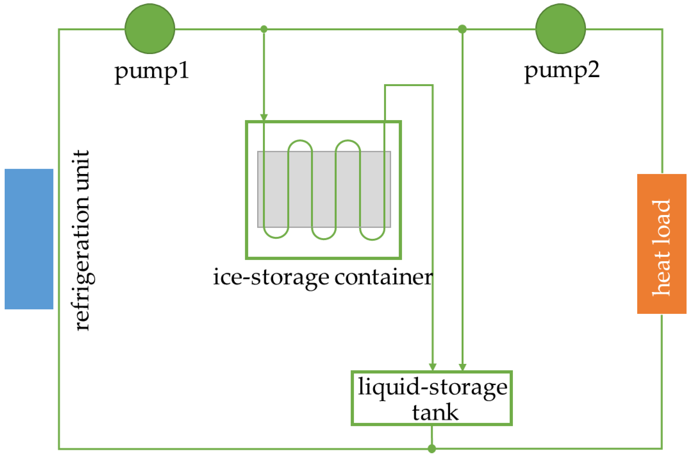
As shown in Figure 1, the cyclic experimental system consists of an ice-storage container, a liquid-storage tank, a refrigerator, a heat load, and two pumps, which are connected by pipes. A coil-plate heat exchanger is placed in the ice-storage container. The refrigerator unit provides cold energy to the coolant in ice-storage mode. The refrigeration unit is self-made with a Copeland scroll ZP83KCE-TFD type compressor. The refrigeration fluid is R410A. The heat load consumes the cold energy and provides the coolant a constant temperature in the melting mode. The coolant is a 30 wt% ethylene glycol solution with a freezing point of approximately −13 °C. The physical properties of the ethylene glycol are obtained from ASHRAE handbook-Fundamental 2017 and are listed in Table 1. The dynamic viscosity decreases when its temperature increases.

Figure 1.
Schematic of the cyclic experimental system.

Table 1.
Physical properties of the ethylene glycol [13].
When the system is in ice storage mode, water in the container is cooled down to solidification by heat exchanging with the cold coolant flowing through the refrigerator. When the ice melting mode is on, the cold energy stored in ice transfers to the coolant and is consumed in the heat load with the coolant heated to 20 °C. The coolant temperatures at the inlets and outlets of the coil-plate units are measured by T-type thermocouples on the outer walls of the inlets and outlets of the coil tubes, and the accuracy of temperature measurements was calibrated to be 1 °C. The coolant volume flow rate is measured by liquid turbine flow meters with an accuracy class 1.0, which means that in the measurement range, the deviation between the actual value and the measured one is not great than 1%.
The photographs of the ice-storage container and the coil-plate heat exchanger are shown in Figure 2. The ice-storage container is in an internal size of 1000 mm × 900 mm × 200 mm, and its walls are made of stainless steel with insulation material covered. As shown in Figure 3a, several pieces of coil-plate units are vertically inserted in the ice-storage container and the inlets and outlets of the coils are connected to the respective main pipes. The number and spacing of the units can be decided according to the demand. In this case, there are 10 pieces of the units and the spacing between the adjacent coil-plate units fixed by buckles is 20 mm. The thermocouples are located on the outer walls of inlets and outlets of the coil tubes, above the water.
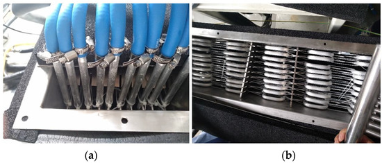
Figure 2.
Photographs of the ice storage container (a) and coil-plate heat exchanger (b).
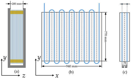
Figure 3.
Schematic of ice storage container (a), coil-plate unit (b), and tube-sheet units (c).
As shown in Figure 3b, the coil-plate unit is spliced by 12 tube-sheet units, and the serpentine coil is formed by connecting the adjacent tubes with curved ones. The plane dimension of the unit is designed as 940 mm × 770 mm because of the limit of the container volume. The tube-sheet unit is detachable and its width or the tube pitch is 78 mm, as shown in Figure 3c. The tube inner diameter is 10 mm with a wall of 1.5 mm and the plate thickness is 3 mm. All the complete coil-plate heat exchanger is made of aluminum alloy.
2.2. Simulation Model
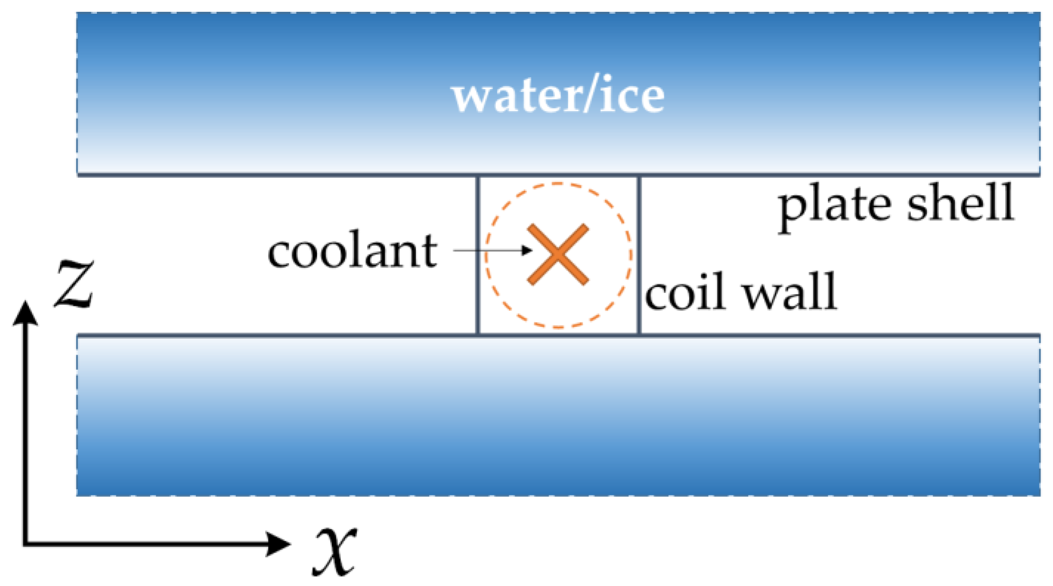
A simulation model for the cooling process of a single coil-plate unit has been built to obtain the heat exchange power density. Because of the stack arrangement of the units in the container, the ices outside the shell are assumed to be in the same thickness and with the adiabatic external surfaces. As shown in Figure 4, a coil-plate unit is simplified into a thin shell with a circular section coil inside.

Figure 4.
Simulation model for cooling process of the coil-plate unit (x–z section).
The software NX I-DEAS, a finite element method (FEM) simulation software, is adopted to build the model. Three main heat transfer processes are considered, namely the convection between the coolant and the coil walls, the heat conduction in the coil walls and plate shells, and the conduction and convention between the plate shells and the ice or water.
The coolant flow in the coil is simplified as a 1-D flow and meshed by beam elements. For the convection between the coolant and the coil wall, it follows Newton’s law of the convection below:
where q′′ is the heat transfer density of convection, and Tw and Tl are the temperature of the coil wall and coolant, respectively. The heat transfer coefficient hl can be calculated as follows:
where kl is the thermal conductivity of the coolant and d is the hydraulic diameter of the coil tube. Nud is the Nusselt number and can be calculated by the following equations:
where Red and Prl are the Reynolds number of the flow in the coil and Prandtl number of the coolant respectively, and A is the cross-sectional area of the coil tube. When Red is larger than 2300, the flow in the coil is turbulent, and when Red is smaller than 2000, the flow is laminar. When Red is in the range of 2000–2300, Nud is a smooth function related to turbulence and laminar flow.
In the coil-plate wall and the ice/water, only heat conduction is considered, and the thermal diffusion equation is
where k, ρ, and cp are the thermal conductivity, density, and specific heat capacity of the materials of coil-plate wall or the ice/water, respectively. Particularly, because the coil wall and plate shell are quite thin, the conduction in the coil-plate unit can be assumed as 2-D. The thermal diffusion equation is solved in a finite difference method.
To simplify the heat transfer process in the model, the convection between the plate and the water is ignored. There are some assumptions about the physical properties of the ice and water, which are listed in Table 2. The density of ice/water is consistently assumed as 920 kg/m3 of ice, not 1000 kg/m3 of water. The phase-change latent heat is substituted with the high specific heat in the range of ± 0.5 °C around the phase-change temperature by equivalent specific heat method, and the maximum of the specific heat is 668,000 J/(kg·K) at 0 °C. The ambient temperature is set as 20 °C and the initial temperature of the system is −2 °C
Table 2.
Physical properties of the ice and water in simulation.
3. Results and Discussion
3.1. Model Verification
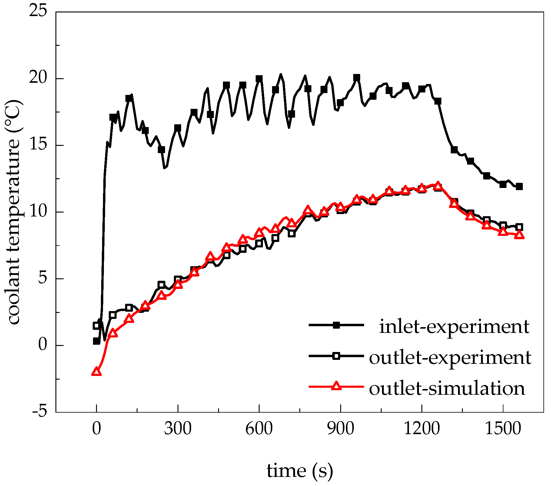
In the experiment, the ice melting mode lasted 20 min and average coolant volume flow rate was measured as 2.57 m3/h. The change of the coolant temperatures at the inlet and outlet in this time period are shown in Figure 5. The inlet temperature fluctuated around 18 °C and the outlet temperature increased with time and was always below the inlet temperature. At 900 s, the temperature difference between the inlet and outlet was approximately 8 °C. The average heat exchange power calculated from the experimental results was 30.0 kW, and the power density was approximately 4.1 kW/m2.
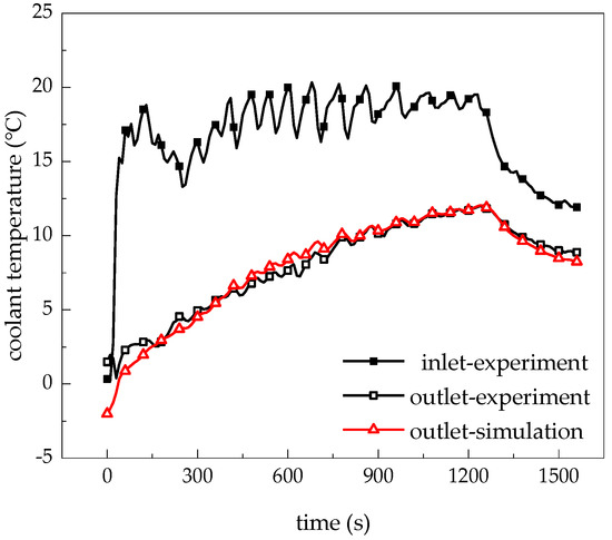
Figure 5.
Coolant temperatures at inlet and outlet in experiment and simulation.
The outlet temperatures can be calculated by taking the inlet temperature and volume flow rate values of one unit as the conditions of the simulation model and are added in Figure 5. Comparing the simulated outlet temperatures with the experimental ones, it is shown that the maximum deviation is less than 1 °C. The experimental results can be well predicted by the simulation model.
3.2. Effects of Unit Structural Parameters
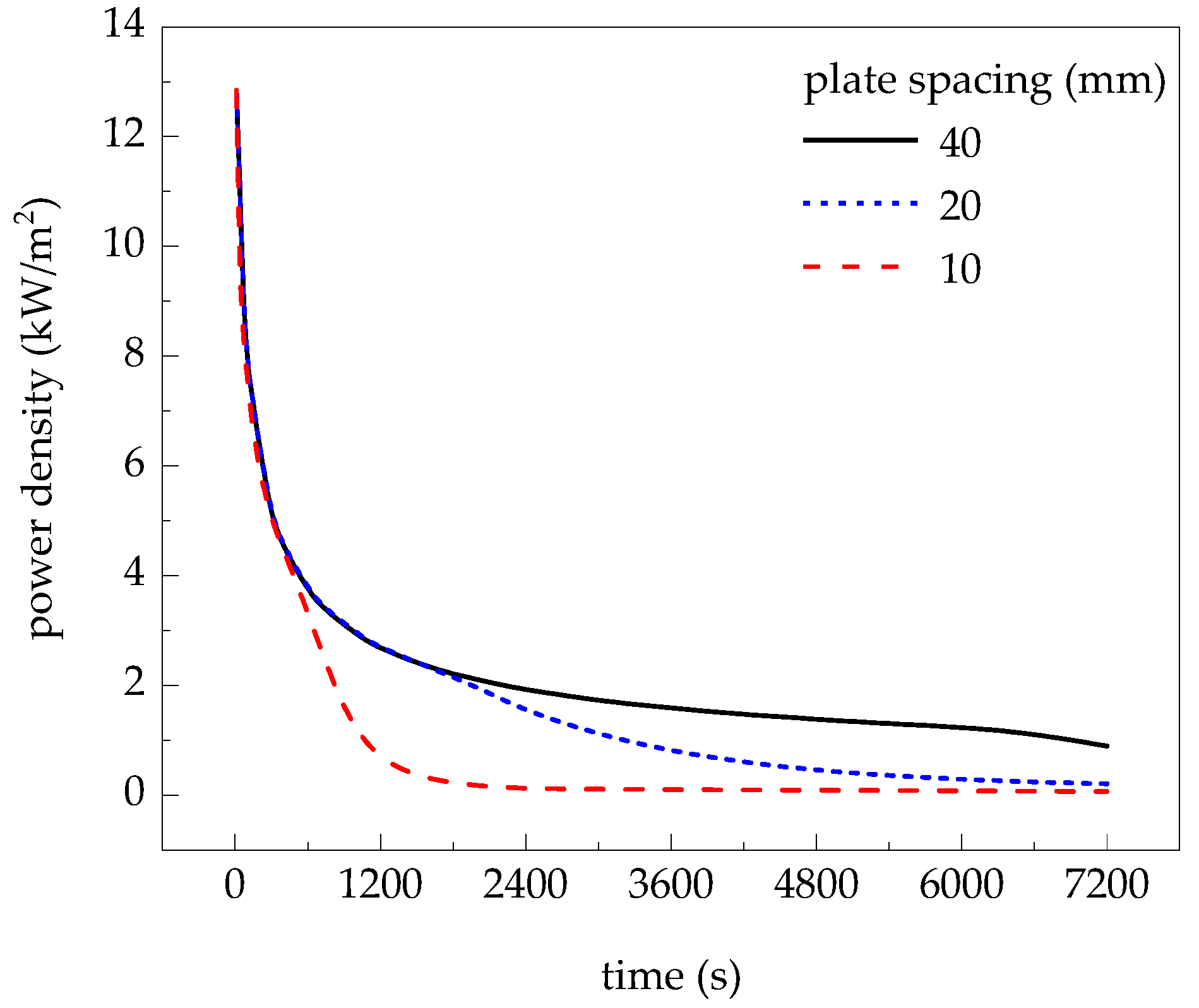
Under the coolant condition with the inlet temperature of 20 °C and the volume flow rate of 0.5 m3/h, the heat exchange power densities of the coil-plate unit in different plate spacing cases are shown in Figure 6. When the plate spacing is smaller, the heat exchange power density decreases earlier and more rapidly because of the limit of the ice storage capacity. The time when the power density begins the abnormal decrease is 600 s for 10 mm plate spacing case, and is 2000 s for 20 mm plate spacing case. When the first 900 s is considered, for the case of 20 mm plate spacing, the minimum heat exchange power density is 3.1 kW/m2 and the average can be as high as 5.1 kW/m2.
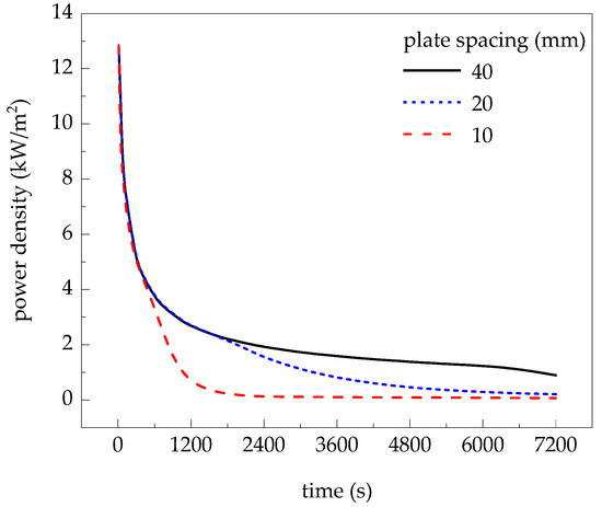
Figure 6.
Effect of plate spacing on heat exchange power density of coil-plate unit.
Because the coil-plate unit is spliced by periodic tube-sheet units, a simple model of a single tube-sheet unit is built. Outside both sides of the unit, there are water layers covered by the unmelted ice layers, and the temperature of water/ice interface is 0 °C. In the cooling process, the water/ice interfaces move outward, and the water thickness increases from 0 to the plate spacing. It is found that the time of the ice melting to a fixed position is hardly affected by the ice layer thickness according to the simulation results of the transient process, and the steady-state heat transfer process in the tube-sheet unit is calculated.
According to the analysis of the temperature field of the flat solar collector [14,15], the influences of the coolant and the structure of the tube-sheet unit on the heat exchange power are obtained. The equation of the power density is as follows:
where and . is the heat exchange power density of the unit, W/m2. Tf and T0 are the coolant temperature in the tube and the interface between water and ice, respectively, °C. dw, W, D, L, and δ are the water thickness, sheet width (i.e., tube pitch), tube diameter, sheet length, and sheet thickness, respectively, m. kw and k are the thermal conductivities of water and plate material, respectively, W/(m·K). h is the convective heat transfer coefficient between the coolant and the tube wall, W/(m2·K).
The calculated power densities were compared with the simulated ones, and the differences are within 5% when the water layer is thicker than 4 mm and the coolant volume flow rate is larger than 0.125 m3/s. It is a simplified method to analyze the influences of the structural parameters of the tube-sheet unit on its heat exchange power based on Equation (5).
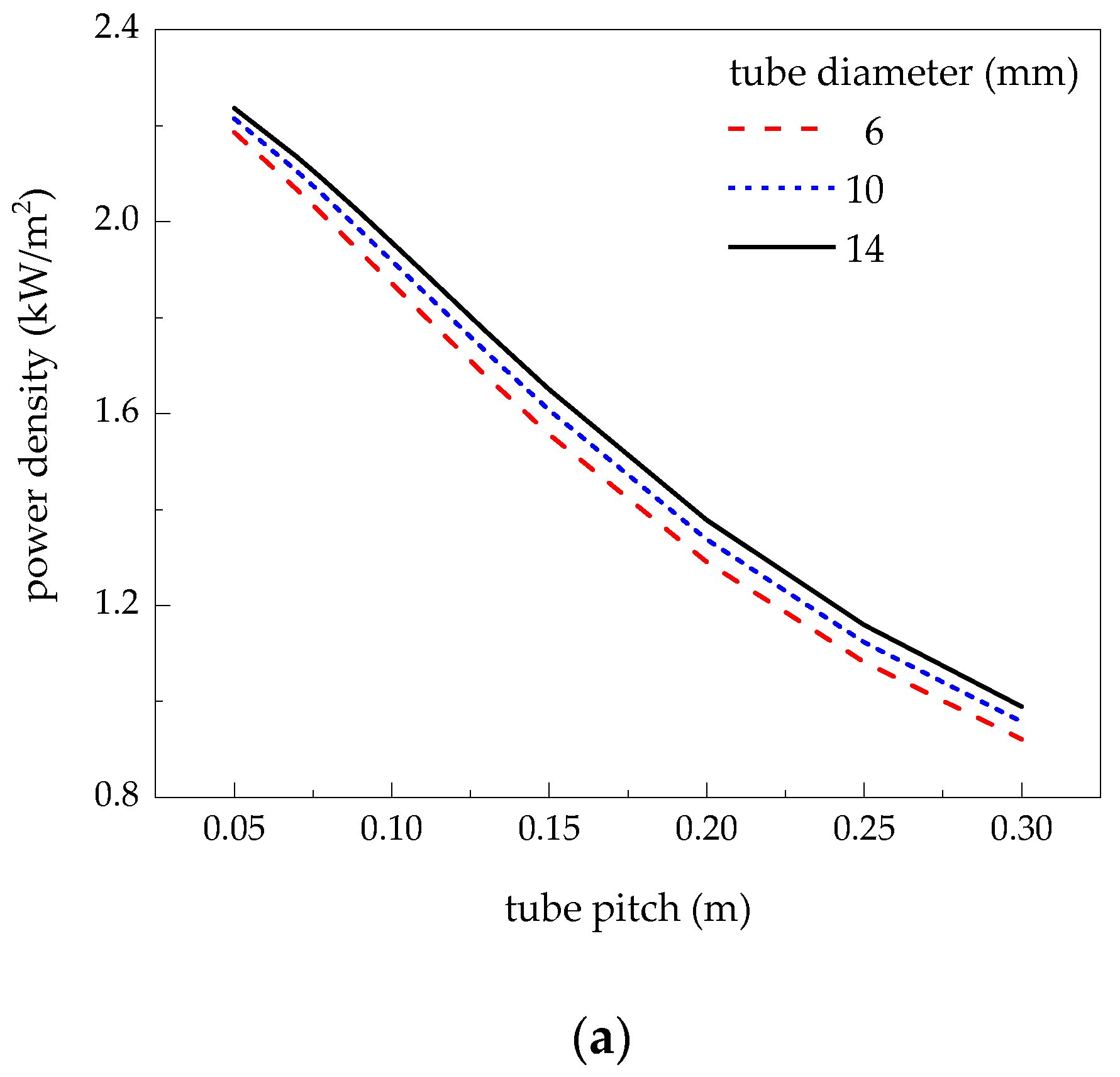
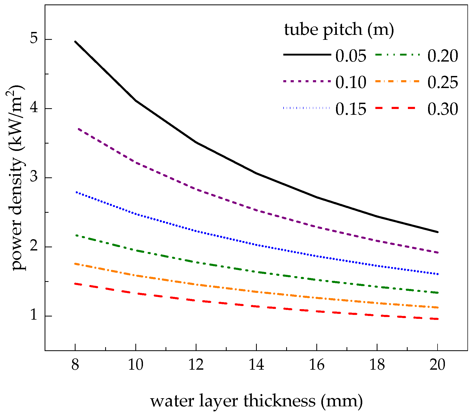
When the inlet coolant condition is 20 °C and 0.5 m3/h, the effects of unit structural parameters on the heat exchange power density are shown in Figure 7 and Figure 8. Figure 7a shows that the power density decreases with the increase of the tube pitch and the tube diameter has small effect on the heat exchange power density when it is around 10 mm because of the small thermal resistance between the coolant flow and the tube wall. In Figure 7b it can be seen that the decrease of the power density slows down with the increase of the water layer thickness. In Figure 8, it is shown that the heat exchange power density decrease with the increase of the water layer thickness. The power density can reach its maximum when the tube pitch and the water layer thickness are both smaller.

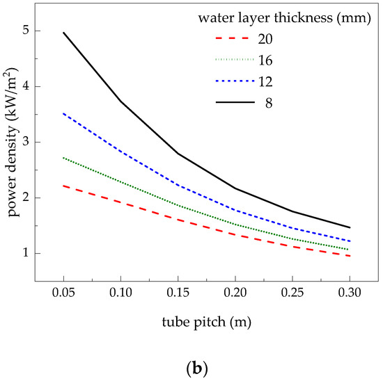
Figure 7.
Effect of tube pitch on heat exchange power density. (a) water layer thickness = 20 mm. (b) tube diameter = 10 mm.
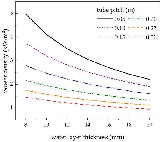
Figure 8.
Effect of water layer thickness on heat exchange power density. (tube diameter = 10 mm).
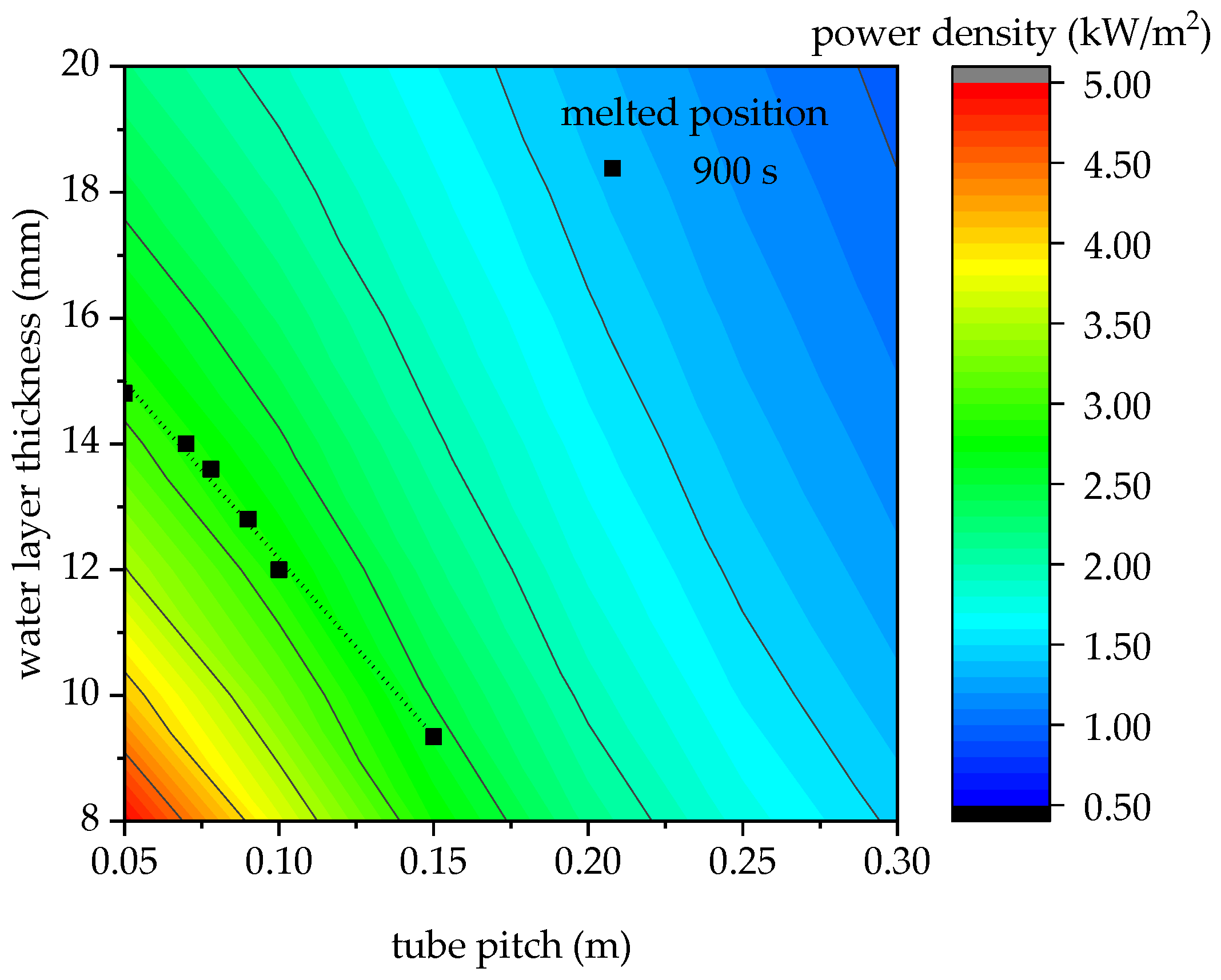
In order to visually analyze the effects of the tube pitch and water layer thickness on the heat exchange power density of the tube-sheet unit, the power densities are expressed in a contour map as shown in Figure 9, and the average melting positions at a fixed time of 900 s are added in the map. It is shown that the angle between the ice melting position line and the contour line of the power density is small, which means that in the fixed time period, the final power densities of units with different structural sizes tend to be the same. When the tube pitch is smaller than 0.10 m, the power density corresponding to the 900-s line is close to 2.9 kW/m2, then it decreases to 2.6 kW/m2 when the tube pitch is 0.15 m. On the line with a fixed time, the smaller tube pitch corresponds to a larger water layer thickness, namely a larger volume of the ice, which also means a higher average heat exchange power density in the effective time period.
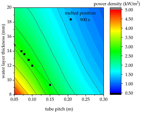
Figure 9.
Heat exchange power density with tube pitch and water layer thickness.
When the tube pitch is small, the ice melts quickly because of the relatively high power density. In order to ensure a sufficient cooling time period, a larger ice storage capacity is needed, leading to a larger water/ice layer thickness or plate spacing. When the tube pitch is large, a smaller ice storage capacity and ice layer thickness can meet the demand of the cooling time period because of the low power density and the slow rate of ice melt. In other words, a large tube pitch and plate spacing are required to ensure adequate cooling time period, and a small tube pitch and plate spacing are required to ensure the lower bound of the heat exchange power density. For a single tube-sheet unit, to ensure the lower bound of the heat exchange power, a large tube pitch and a small plate spacing are needed.
3.3. Effects of Coolant Temperature and Volume Flow Rate
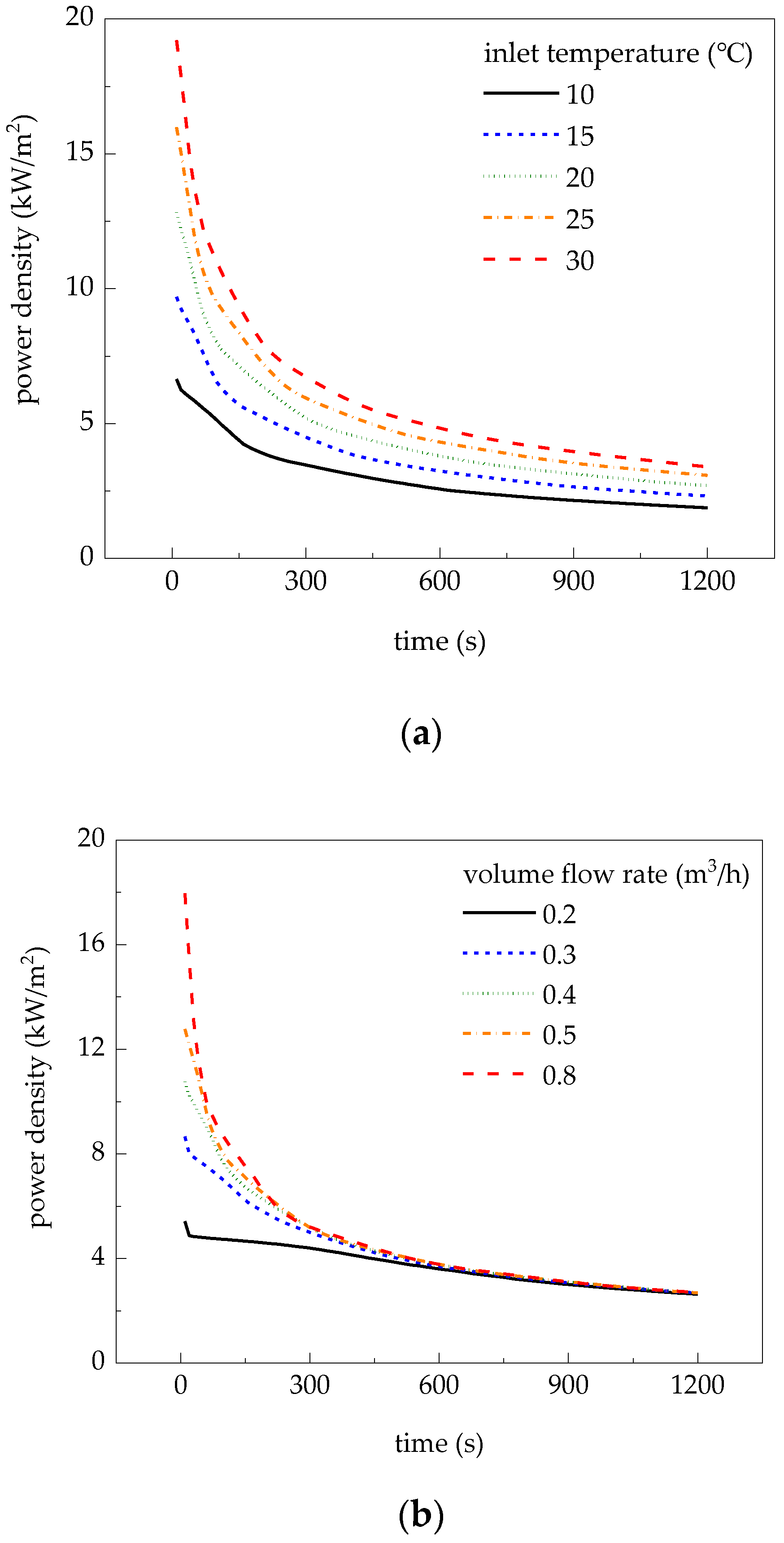
The numerical results of the coil-plate unit with a 20 mm plate spacing are shown in Figure 10. Figure 10a shows that the heat exchange power density increases with the increase of the coolant inlet temperature. Figure 10b shows that the effect of the coolant volume flow rate on the power density is small when the volume flow rate is larger than 0.3 m3/h. While the coolant volume flow rate increases, the difference between the temperature at the coil inlet and outlet decreases, resulting in a small change in the heat exchange power by offsetting the advantage of the large volume flow rate. For the small coolant volume flow rate such as 0.2 m3/h, the heat exchange power is much lower than that for a larger volume flow rate, because of the weak convection heat transfer in the coil. When the coolant temperature is lower than 10 °C, the larger viscosity of the coolant causes the flow in the coil tube to be laminar, leading to lower convective heat transfer coefficient h, as shown in Figure 11.
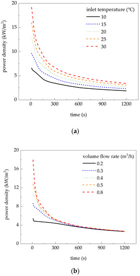
Figure 10.
Effects of coolant conditions on heat exchange power density. (a) volume flow rate = 0.5m3/h. (b) inlet temperature = 20 °C.
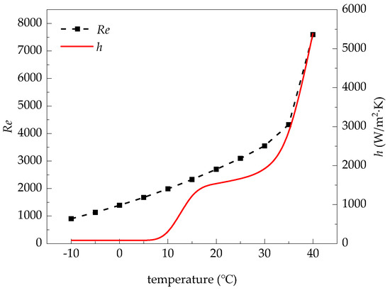
Figure 11.
Re number and convection coefficient of coolant with temperature.
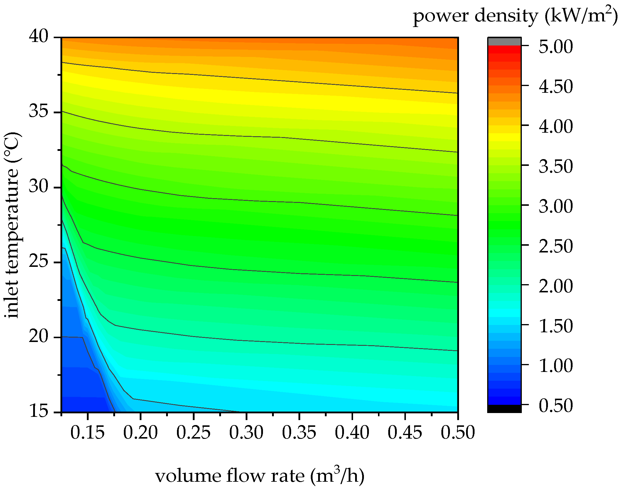
Figure 12 shows the numerical results of the tube-sheet unit with a 20 mm plate spacing. The heat exchange power is at a higher level when the volume flow rate or the inlet temperature is high. In the triangular region with the volume flow rate less than 0.2 m3/h and the inlet temperature below 30 °C, the power is much lower than the values under other conditions. When the inlet temperature is low, the viscosity of the coolant will be large, and if the volume flow rate is small at the same time, the coolant is in a laminar state in the tube with a Re number less than 2000. The convective heat transfer power between the coolant and the tube wall is limited, resulting in a low heat exchange power. When the temperature is high or the volume flow rate is large, the coolant is in a turbulent state in the tube with a Re number more than 2300. The thermal resistance between the coolant and the wall is smaller than that between the sheet and the water outside.
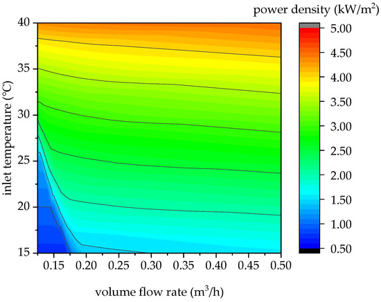
Figure 12.
Heat exchange power density with different inlet temperature and. Volume flow rate of coolant.
4. Conclusions
In order to obtain the maximal cooling effect in a limited time period, the influences of the unit structural parameters and the coolant temperature and volume flow rate on the heat exchange power density of the coil-plate unit have been analyzed. It is found that when the sizes of the tube pitch and plate spacing are both large, the heat exchange power density is limited, and when the sizes are small, the cooling time period is limited. The small plate spacing can make the power density decrease rapidly in the later stage. The inlet coolant temperature can affect the heat exchange power density significantly, and the coolant volume flow rate in the tube has a small effect on the power density when the coolant is in turbulent state. In a time period of 900 s, for a coil-plate heat exchanger with a plate size of 940 mm ×770 mm and the tube pitch of 78 mm, when the plate spacing is 20 mm, the average heat exchange power density is 5.1 kW/m2 under the condition of the coolant in 20 °C and 0.5 m3/h.
Author Contributions
All authors contributed equally to this work. Detailed contribution is described as follows: Conceptualization, H.Y.; simulation, experiment, and writing, L.G.
Funding
This research was funded by the National Natural Science Foundation (No. 51576188).
Conflicts of Interest
The authors declare no conflict of interest.
References
- Wallace, J. Keep your laser-diode system cool, whatever the power. Laser Focus World 2018, 54, 75–77. [Google Scholar]
- Guan, C.; Li, L.; Ji, H.M.; Luo, S.; Xu, P.; Gao, Q.; Lv, H.; Liu, W. Fabrication and Characterization of a High-Power Assembly With a 20-Junction Monolithically Stacked Laser Power Converter. IEEE J. Photovolt. 2018, 8, 1355–1362. [Google Scholar] [CrossRef]
- Smyth, C.J.C.; Mirkhanov, S.; Quarterman, A.H.; Wilcox, K.G. Thermal management of VECSELs by front surface direct liquid cooling. In Vertical External Cavity Surface Emitting Lasers; Wilcox, K.G., Ed.; SPIE-INT SOC OPTICAL ENGINEERING: Bellingham, WA, USA, 2016. [Google Scholar]
- Cheng, X.; Shang, J. Thermal behavior of micro-channel cooled thin-slab Fe:ZnSe lasers. Optik 2017, 143, 66–70. [Google Scholar] [CrossRef]
- Beni, S.B.; Bahrami, A.; Salimpour, M.R. Design of novel geometries for microchannel heat sinks used for cooling diode lasers. Int. J. Heat Mass Transf. 2017, 112, 689–698. [Google Scholar] [CrossRef]
- Seo, M.J.; Lee, J.H.; Park, S.R.; Park, S.Y.; Kim, S.M. Effects of the Various Cooling Conditions on 1,064-nm nd:Yag Laser Treatment for Selective Photothermolysis. Exp. Heat Transf. 2014, 27, 488–500. [Google Scholar] [CrossRef]
- Shu, S.; Hou, G.; Wang, L.; Tian, S.; Vassiliev, L.L.; Tong, C. Heat dissipation in high-power semiconductor lasers with heat pipe cooling system. J. Mech. Sci. Technol. 2017, 31, 2607–2612. [Google Scholar] [CrossRef]
- Novak, V.; Podobnik, B.; Možina, J. Analysis of the thermal management system for a pump laser. Appl. Therm. Eng. 2013, 57, 99–106. [Google Scholar] [CrossRef]
- Hasnain, S.M. Review on sustainable thermal energy storage technologies, Part II: Cool thermal storage. Energy Convers. Manag. 1998, 39, 1139–1153. [Google Scholar] [CrossRef]
- Wang, C.; He, Z.; Li, H.; Wennerstern, R.; Sun, Q. Evaluation on performance of a phase change material based cold storage house. In Proceedings of the 8th International Conference on Applied Energy, Beijing, China, 8–11 October 2016; Yan, J., Sun, F.C., Desideri, U., Li, H., Campana, P., Xiong, R., Eds.; ELSEVIER SCIENCE BV: Amsterdam, The Netherlands, 2017. [Google Scholar]
- Oró, E.; De Gracia, A.; Castell, A.; Farid, M.M.; Cabeza, L.F. Review on phase change materials (PCMs) for cold thermal energy storage applications. Appl. Energy 2012, 99, 513–533. [Google Scholar] [CrossRef]
- Maiorino, A.; Del Duca, M.G.; Mota-Babiloni, A.; Greco, A.; Aprea, C. The thermal performances of a refrigerator incorporating a Phase Change Material. Int. J. Refrig. 2019, 100, 255–264. [Google Scholar] [CrossRef]
- ASHRAE. Physical Properties of Secondary Coolants (Brines). In ASHRAE Handbook: Fundamentals; American Society of Heating, Air-Conditioning and Refrigeration Engineers: Atlanta, GA, USA, 2017. [Google Scholar]
- Zhou, F.; Ji, J.; Cai, J.; Yu, B. Experimental and numerical study of the freezing process of flat-plate solar collector. Appl. Therm. Eng. 2017, 118, 773–784. [Google Scholar] [CrossRef]
- Duffie, J.A.; Beckman, W.A. Solar Engineering of Thermal Processes, 4th ed.; John Wiley & Sons: New York, NY, USA, 2013. [Google Scholar]


© 2019 by the authors. Licensee MDPI, Basel, Switzerland. This article is an open access article distributed under the terms and conditions of the Creative Commons Attribution (CC BY) license (http://creativecommons.org/licenses/by/4.0/).