1. Introduction
The integration of distributed renewable energies (DREs) into power systems has been increasing rapidly in recent years [
1,
2]. Such a trend is transforming the conventional passive distribution networks into active networks with advanced control systems [
3,
4]. As a new pattern of the active distribution networks, multiple microgrids (MMGs) which are composed of a cluster of interconnected microgrids have been proposed and studied. They organize and manage a certain number of microgrids in a systematic way to integrate and utilize a large number of DREs [
5,
6]. Currently, MMGs have broad application prospects due to their complementarity and coordination. Therefore it is necessary to investigate the control schemes for MMGs to fully explore their complementarity, their potential of optimized operation, and make them coordinated and friendly systems both to the utility grid and the sub-microgrids.
Grid-connected operation is an important operation mode of MMGs. Many studies on control schemes for grid-connected MMGs have been done for the purpose of economic and optimized operation. Reference [
7] proposes a distributed economic model predictive control scheme for multi-microgrids to maintain the system-wide supply and demand balance in an economical manner. Reference [
8] presents a coordinated operation approach based on a two-stage adaptive robust optimization to mitigate the influence of the uncertainty in intermittent renewable energies and minimize the daily operation cost of the system. Economic dispatch strategies for multiple networked microgrids considering privacy preservation are investigated in [
9,
10]. A model predictive control for the optimal power exchange in MMGs to maximize the global benefits of the system is introduced in [
11]. Reference [
12] presents a novel interface control strategy for desirable load sharing among the interconnected microgrids and assesses the system stability under such a control framework. The studies introduced above put forward different control schemes for grid-connected MMGs to achieve economic and optimized operation. However, the studied AC interconnected microgrids might lead to negative operation problems including electromagnetic loop networks, mutual electromagnetic influence under faults, inconvenient multi-voltage-level interconnection, and lack of high controllability [
13]. Hence, limited potential of friendly and coordinated operation among the sub-microgrids and the utility grid is explored by current control schemes. Furthermore, due to the AC coupling among the microgrids, the control system is strongly coupled and the advantages of the clustering of microgrids especially the high controllability and coordination cannot be fully exploited.
With the advancement of power electronic technologies, DC interconnected MMGs are anticipated to be an advanced MMGs configuration due to the favorable controllability and operation characteristics of the DC connection interfaces [
14]. The DC interconnection among the microgrids is able to promote the flexible and optimized operation of the MMGs via the advanced control system. Hence, research on the grid-connected control schemes for DC interconnected MMGs needs in-depth investigation.
Reference [
15] proposes a coordination strategy for the optimal scheduling of MMGs based on a hierarchical system. It enables the microgrids that are interconnected with back-to-back converters to directly share power with each other so as to minimize the operation cost of the MMGs. Reference [
16] utilizes multi-terminal low-voltage direct current in distribution network to connect multiple feeders or transformers. A corresponding adaptive droop control strategy is proposed to improve the integration capacity of plug-in electric vehicles in the distribution system. Reference [
17] presents an efficient control strategy for MMGs to preserve power quality of the system and improve system reliability through the interconnection converters. In the authors’ previous work, a novel MMGs architecture based on a hybrid AC/DC connection interface is designed and a coordinated control framework for different operation conditions is proposed. The control framework enables the flexible and coordinated operation of the MMGs and enhances the integration capacity of a large number of DREs in the system [
13]. Since the concept of DC interconnected MMGs is relatively new, research on the grid-connected control schemes for DC interconnected MMGs is not sufficient and comprehensive. In addition, the coordinated operation of DC interconnected MMGs and its operation friendliness should be investigated in depth in order to eliminate the technical obstacles to the grid-connected operation of MMGs and promote its practical application [
18]. It is worth mentioning that the concept of operation friendliness for the MMGs includes the operation friendliness to the utility grid and the operation friendliness to the sub-microgrids. It describes the ability of the MMGs to exchange optimized power with the utility grid as well as the ancillary services provided to the utility grid by the MMGs. It also describes the ability of the MMGs to coordinate and optimize the operation of the sub-microgrids.
The hybrid-connection-interface-based MMGs introduced in [
13] is studied in this paper and a multi-layer coordinated control scheme for its grid-connected operation is proposed accordingly. The multi-layer coordinated control scheme is designed to adequately exploit the complementarity and coordination of the MMGs, as well as improve its operation friendliness so as to eventually promote the integration and utilization of a large number of DREs. An adaptive droop control method is designed for the DC connection interfaces of the MMGs to properly share power among the sub-microgrids and improve the sub-microgrids’ coordination. Meanwhile, the hybrid energy storage system (HESS), which is composed of batteries and a superconducting magnetic energy storage (SMES) device, is utilized in the MMGs and the strategy of power fluctuation suppression is developed for the HESS. Then, the proposed multi-layer coordinated control scheme clarifies the coordination among the sub-microgrids and the HESS so as to optimize the AC tie-line power as flat as possible and make the MMGs a highly coordinated collective.
Compared with previous related studies, the main contributions of this paper are: (1) A multi-layer control architecture is specifically designed for the DC interconnected MMGs and the coordination among the sub-microgrids and the HESS is clarified; (2) The control and coordination characteristics of the DC interconnected MMGs are fully utilized and the advantages of the clustering of microgrids are fully exploited; (3) The operation friendliness of the DC interconnected MMGs is improved and the integration and utilization of a large number of DREs is enhanced.
The rest of the paper is organized as follows:
Section 2 briefly introduces the configuration of the MMGs and the system control architecture.
Section 3 presents the multi-layer coordinated control scheme in detail. Simulation results are shown and analyzed in
Section 4. Conclusions are drawn in
Section 5.
3. Proposed Multi-Layer Coordinated Control Scheme
The grid-connected MMGs has the potential of integrating a large number of DREs, which makes it undesirable to the utility grid due to the intermittence and uncertainty of DREs. To facilitate the integration and utilization of a large number of DREs, the coordinated operation of the MMGs needs investigation and the operation friendliness of the MMGs needs improving. From the perspective of the utility grid, optimized power is expected to be provided or absorbed by the MMGs. Therefore the control of the AC tie-line power is very important. Reference [
27] proposes a concept called flat tie-line power scheduling to maintain the tie-line power flow of the grid-connected microgrids as flat as possible during a determined period of time. This concept solves the problems of low-frequency power flow fluctuation and lack of controllability that exist in other tie-line power flow control methods. In this study, the flat AC tie-line power of the MMGs is also anticipated to improve the MMGs’ operation friendliness to the utility grid. In the meantime, the coordinated operation among the sub-microgrids and the HESS is studied and clarified to enhance the MMGs’ operation friendliness to the sub-microgrids. In general, the overall control objective of the proposed multi-layer coordinated control scheme is to fully exploit the complementarity of the MMGs, make the MMGs a highly coordinated collective, and improve the operation friendliness of the MMGs so as to eventually enhance the integration and utilization of a large number of DREs. Three specific control objectives to achieve the overall control objective are listed as follows:
- (1)
To optimize the AC tie-line power of the MMGs as flat as possible during every dispatch period;
- (2)
To properly manage the power exchange among the sub-microgrids via the MMCs in order to enhance the coordinated operation of the sub-microgrids;
- (3)
To effectively suppress the power fluctuation of the MMGs via the coordination within the HESS.
3.1. AC Tie-Line Power References Assignment
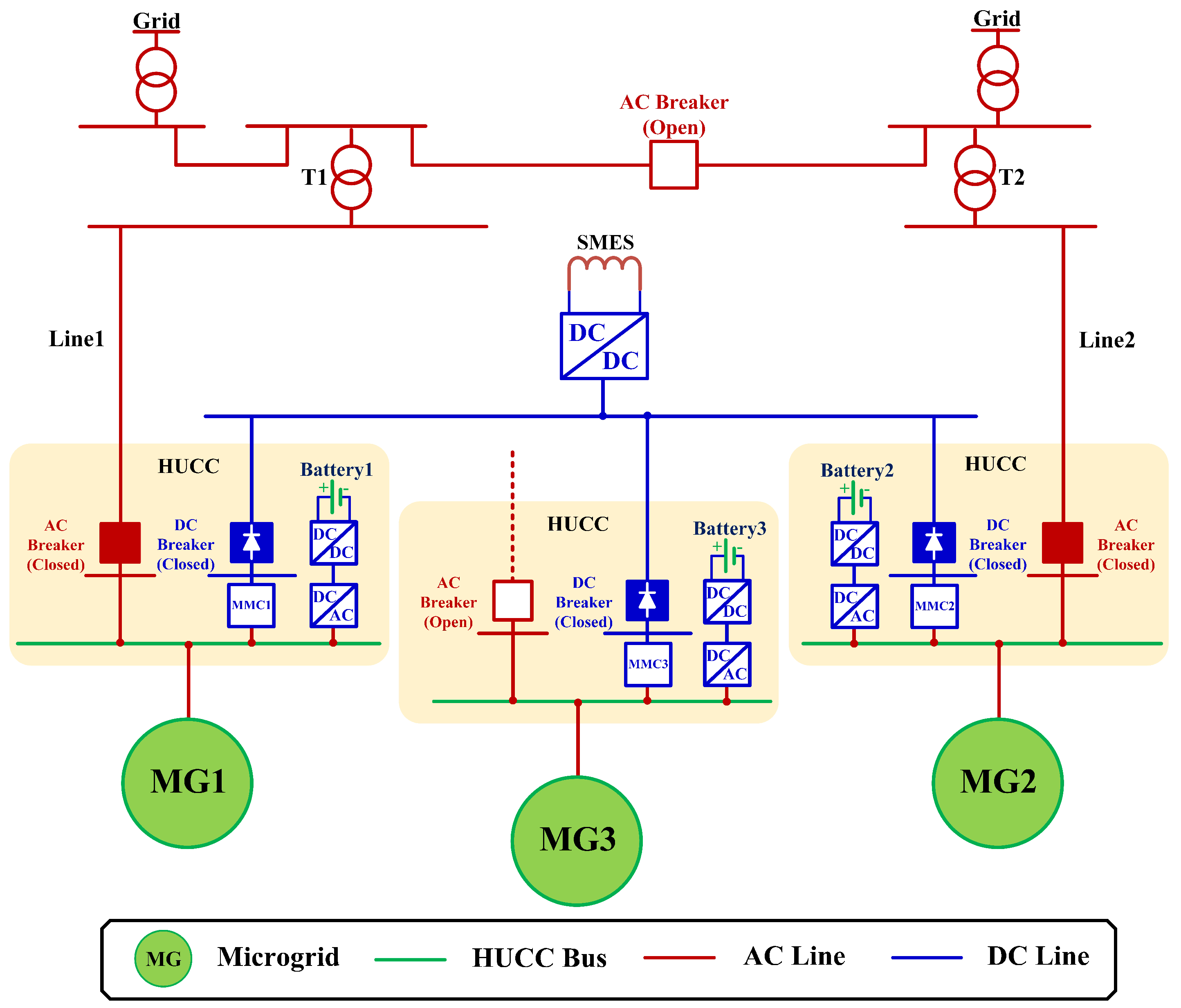
PV modules, wind turbines (WTs), and diesel generators are common DGs in microgrids. They are implemented in every sub-microgrid of the MMGs in this study. The PV modules and WTs are controlled to work at the maximum power points to utilize the DREs as much as possible while the diesel generators control the voltage and frequency of islanded sub-microgrids. As is shown in
Figure 1, the utility grid provides voltage and frequency support for MG1 and MG2 via the AC tie-lines. Hence the operation of the diesel generators in MG1 and MG2 is not necessary. However, the diesel generator in MG3 has to work on Vf control to maintain the microgrid voltage and frequency since MG3 is not directly connected to the utility grid and the MMCs work on adaptive droop control which will be introduced in
Section 3.3.
Take T as the dispatch period. The proposed multi-layer coordinated control scheme re-calculates the control signals at the beginning of every dispatch period. The value of T could be altered from a few minutes to tens of minutes depending on the variation tendency of the DG output power. T is set to 10 min in this study.
During a dispatch period, the predicted total output energy of the sub-microgrids is calculated based on the prediction curves of the PV power, wind power, and loads. The calculation is as follows:
where
is the beginning time of the dispatch period,
is the predicted total output energy of MG
,
is the predicted PV power of MG
,
is the predicted wind power of MG
,
is the predicted load of MG
, and
is the output power of the diesel generator in MG3. Usually the output power of the diesel generator is regulated within a normal working range, for instance
. Since the grid-connected MMGs aims to maximize the utilization of DREs, the minimal value should be selected for
, that is
. It should be mentioned that the positive direction of power is designated from the DG to the sub-microgrid or from the sub-microgrid to the utility grid and the other sub-microgrids in this paper.
Based on Equation (1), the predicted average output power of the sub-microgrids can be derived as:
where
is the predicted average output power of MG
.
As
Figure 1 shows, MG1 and MG2 are connected to two different feeder transformers. Hence the rated capacity of the feeder transformers should be considered before the excess power of the MMGs is transmitted to the utility grid to optimize power distribution and avoid transformer overload. The predicted average output power calculated in Equation (2) is distributed according to the rated capacity of the feeder transformers and the ideal AC tie-line power references are calculated as:
where
and
are the rated capacity of feeder transformer T1 and T2, respectively, and
is the ideal power reference of AC tie-line
.
According to Equation (3), the predicted excess power of the MMGs is distributed to the two AC tie-lines based on the capacity ratio of the feeder transformers. Such an assignment not only reduces the possibility of transformer overload, but also explores the potential of the feeder transformers to transmit more power to the utility grid, which eventually improves the DRE integration and utilization in the MMGs. It is possible that the economic operation of the MMGs will be impaired due to the power loss under extreme conditions by using the proposed power distribution method. But this issue will be investigated in future work since power loss is not the main focus of this paper. With Equations (2) and (3), the ideal power exchange among the sub-microgrids can be derived as:
where
is the ideal DC output power of MG
.
3.2. Control Strategy of Power Fluctuation Suppression
Section 3.1 introduces the calculation method of the ideal AC and DC output power of the MMGs based on DG power prediction. Nevertheless the intermittence and uncertainty of the DGs may cause the actual DG power deviate from the predicted DG power and lead to system power fluctuation. The HESS is utilized in the MMGs to suppress the power fluctuation and maintain the AC tie-line power flat. It should be noted that the HESS could be used to achieve other control objectives in addition to power fluctuation suppression. But that would require larger capacity configuration, which increases the economic cost of the system. In this work, the HESS with small capacity is adopted to reduce the economic cost since the HESS is only used to suppress the power fluctuation.
During a dispatch period, the fluctuating power of the MMGs is calculated according to the real-time DG power and loads as:
where
is the fluctuating power of MG
,
is the real-time PV power of MG
,
is the real-time wind power of MG
, and
is the real-time load of MG
.
As is introduced in
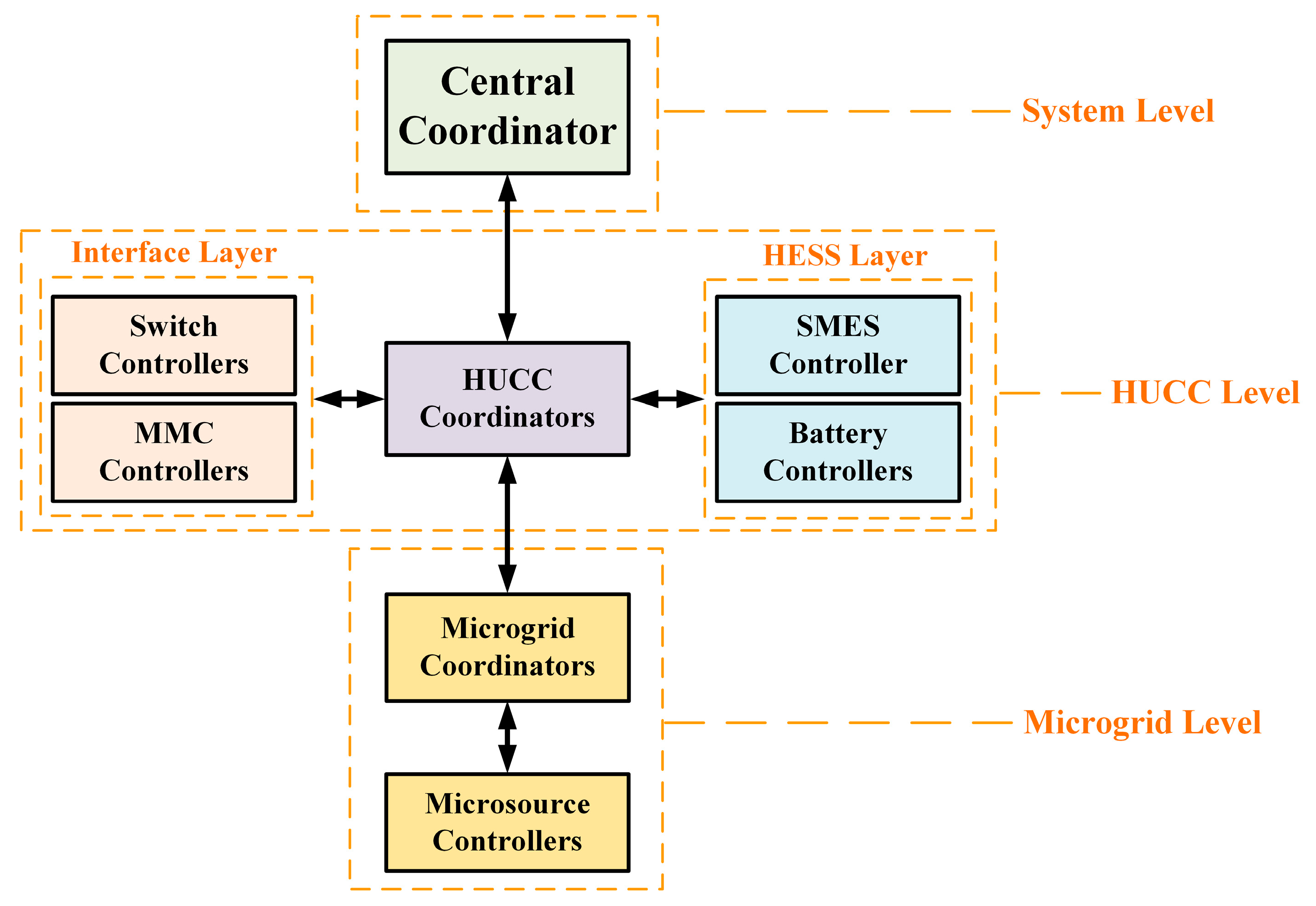
Section 2.1, the batteries are distributedly implemented in the HUCCs of the microgrids and the SMES is centrally implemented to the DC network of the MMGs. Given the architecture of the HESS and the characteristics of the two types of energy storage devices, the control principles for the HESS to suppress power fluctuation are established as follows:
- (1)
The low frequency fluctuating power is suppressed locally in the sub-microgrid by the corresponding battery;
- (2)
The high frequency fluctuating power is transmitted to the DC network via the MMC and suppressed centrally by the SMES.
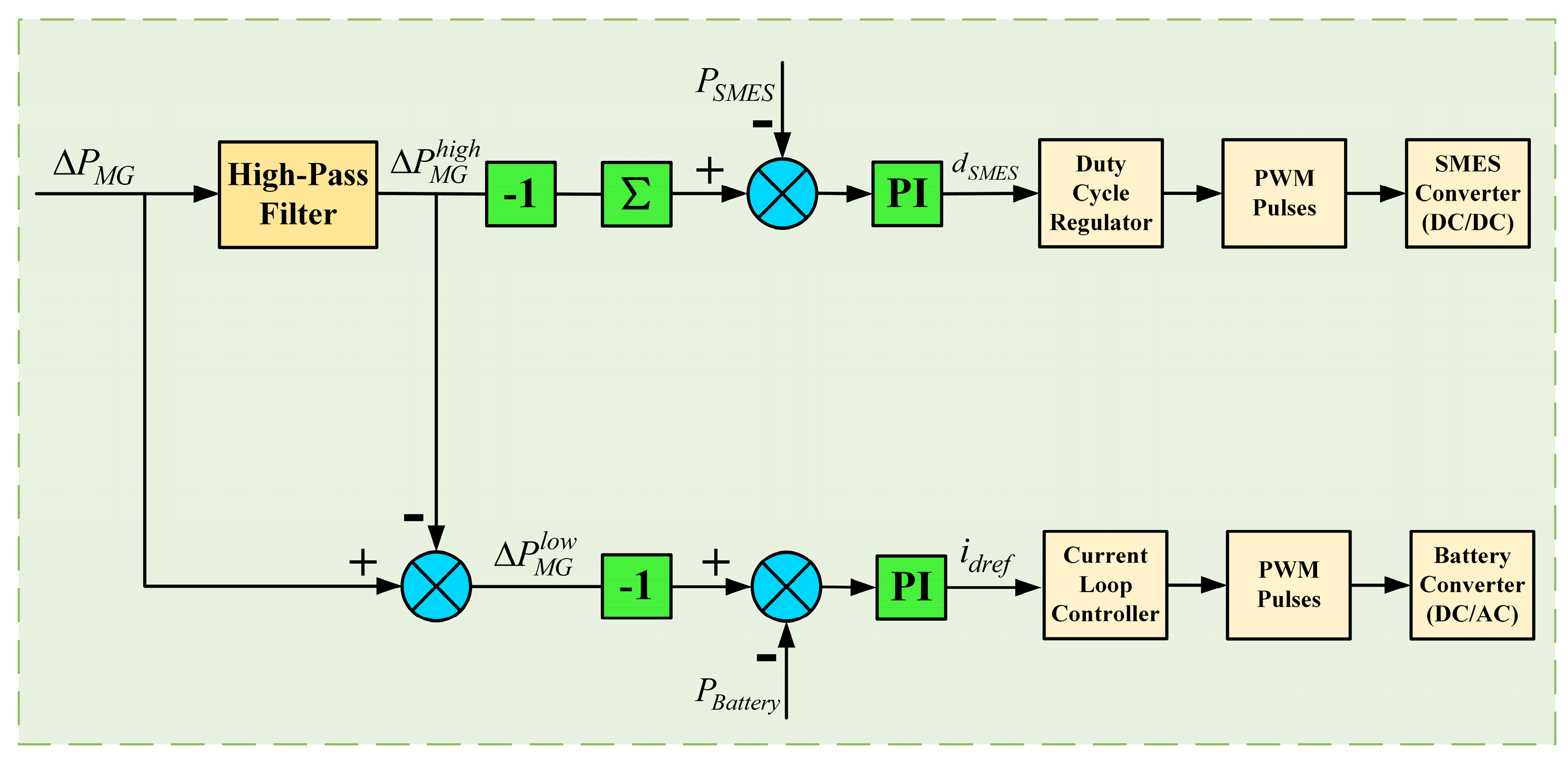
The above control principles specify the coordination within the HESS considering the operating characteristics of the batteries and the SMES. At the same time, the fast response and favorable control characteristics of the MMC are made full use of to transmit the high frequency fluctuating power to the DC network of the MMGs for central suppression. Since the fluctuating power is suppressed both locally and centrally, the AC tie-line power is maintained flat during the dispatch period. The control strategy for the HESS is illustrated in
Figure 3.
As is shown in
Figure 3, the fluctuating power of the microgrids calculated by Equation (5) is first processed by a high-pass filter. As a result, the low frequency and high frequency components of the fluctuating power are obtained. According to the aforementioned control principles for the HESS, the sum of the low frequency fluctuating power (
) should be compensated by the battery. Hence the power reference of the battery is set to (
). Next the real-time power of the battery is subtracted from the power reference and the power error is sent to the PI controller. The PI controller generates the current reference signal (
) for the battery converter under d-q coordinate system. The current reference signal is then sent to the current loop controller to generate PWM pulse control signals and the desired battery power is achieved by the adjustment of the PWM pulses for the battery converter. The control procedure of the SMES is similar to the control procedure of the battery except that the duty cycle reference (
) is generated by the PI controller to generate corresponding PWM pulse control signals.
It is worthwhile noting that the centralized implementation of the SMES has several advantages. The high frequency fluctuating power of the microgrids may cancel each other out in the DC network of the MMGs, hence reducing the capacity configuration and output power of the SMES. As a result, the life span and economy of the SMES are enhanced.
According to the control strategy for the HESS, the real-time power reference of every component in the MMGs is calculated as follows:
where
is the actual power reference of AC tie-line
,
is the real-time DC power reference of MG
,
is the real-time power reference of the battery in MG
, and
is the real-time power reference of the SMES.
3.3. Adaptive Droop Control of MMC
MMC has the advantages of high controllability and fast dynamic response. In the grid-connected MMGs, power is exchanged among the sub-microgrids via the MMCs to coordinate the operation of the sub-microgrids and keep the AC tie-line power at the desired level. Besides, in order to optimize the AC tie-line power as flat as possible, the high frequency fluctuating power of the microgrids is transmitted to the DC network of the MMGs via the MMCs for central suppression. Therefore, the real-time power control of the MMCs is of great importance for the proposed multi-layer coordinated control scheme.
Compared with master-slave control method, droop control method is preferable for the MMCs in the MMGs due to higher reliability. In this paper, an adaptive droop control method is proposed for the MMCs to fastly and adaptively track the variation of the power references of the MMCs. The conventional droop control for multi-terminal MMCs is expressed as follows:
where
is the droop coefficient,
and
are the reference values of the DC voltage and active power, respectively, and
and
are the actual values of the DC voltage and active power, respectively.
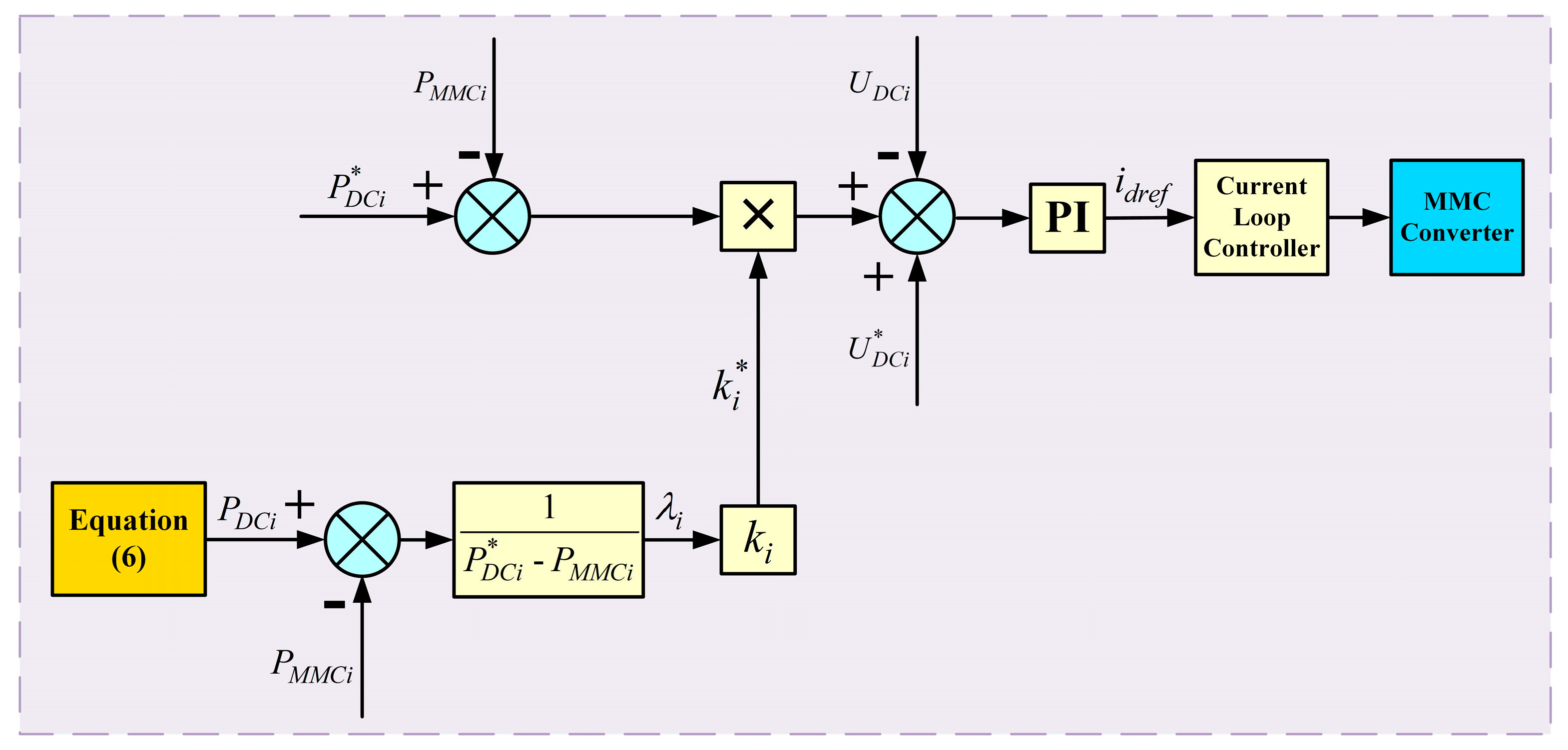
According to Equation (6), the power references of the MMCs vary during the operation of the MMGs. Thus the droop coefficients of the MMCs should be modified to track the variation of the power references. By multiplying the modification factor and the inherent droop coefficient, the modified droop coefficients are calculated as:
where
is the inherent droop coefficient of MMC
,
is the modification factor for
,
is the modified droop coefficient of MMC
,
is the inherent reference value of the active power of MMC
,
is the real-time DC power reference of MMC
, and
is the actual value of the active power of MMC
. Thus the proposed adaptive droop control is expressed as:
where
is the inherent reference value of the DC voltage of MMC
, and
is the actual value of the DC voltage of MMC
.
Based on Equations (8) and (9), the block diagram of the adaptive droop control is illustrated in
Figure 4.
As is shown in the block diagram, the modification factor () is first calculated according to Equation (8). Then it is sent to the droop control to modify the droop coefficient of the MMC by multiplying the inherent droop coefficient (). In this way, the real-time active power reference of the MMC is adaptively tracked.
3.4. Limited Condition of the HESS
The above analysis is based on the assumption that the HESS has enough capacity configuration to release or absorb any amount of energy that is assigned by the multi-layer coordinated control scheme. However, the actual operation of the HESS might not be the case. In this subsection, the “limited condition” of the HESS is taken into account. As for the batteries and the SMES, the “limited condition” is defined as: lack of energy when required to release more energy (over-discharge state) or full of energy when required to absorb more energy (over-charge state). The criteria for the “limited condition” are listed in
Table 1.
As
Table 1 shows, the “limited condition” of the HESS is judged by its energy status as well as the sign of the power assigned by the multi-layer coordinated control scheme. Meanwhile, the energy status of the batteries and the SMES is judged by the SOC and the coil current, respectively. Once the over-charge state or the over-discharge state is detected, the corresponding energy storage device will quit operation for self-protection. Since the capacity configuration of the HESS is not the major concern of this paper, extreme conditions where more than one energy storage device is under the “limited condition” is not considered. When the “limited condition” is detected and the energy storage device quits operation, the deficit/surplus power will be compensated by other energy storage devices in the HESS. The compensation principles are listed as follows:
- (1)
If the SMES is under the “limited condition”, the high frequency fluctuating power of the sub-microgrids will be suppressed locally by the corresponding batteries;
- (2)
If a battery is under the “limited condition”, its assigned power will be supplied by the other two batteries in the HESS according to the rated capacity of the batteries.
Following the compensation principles, the real-time power references of the MMGs calculated in (6) should be modified to cope with the “limited condition” of the HESS. When the SMES is under the “limited condition”, the real-time power references of the MMGs are modified as:
where the variables are the same as those in Equation (6).
As Equation (10) shows, the SMES quits operation and the high frequency fluctuating power assigned for the SMES is suppressed locally by the corresponding batteries and the DC network of the MMGs will not endure any high frequency fluctuating power.
When a battery is under the “limited condition”, its assigned power should be supplied by the other two batteries in the HESS. Take MG1 as an example. Battery2 and Battery3 compensate the assigned power of Battery1 based on their rated capacity. The assigned power of Battery1 is distributed to Battery2 and Battery3 as:
where
and
are the power compensated by Battery2 and Battery3, respectively, and
and
are the rated capacity of Battery2 and Battery3, respectively.
With Equation (11), the real-time power references of the MMGs are modified as:
where the variables are the same as those in Equations (6) and (11).
As Equation (12) shows, the power compensated by Battery2 and Battery3 is transmitted to MG1 via the MMCs to suppress the low frequency fluctuating power of MG1 when Battery1 quits operation. In the meantime, the high frequency fluctuating power of the MMGs is still suppressed centrally by the SMES.
On the basis of Equations (10)–(12), the real-time power references of the MMGs are modified properly during the “limited condition” of the HESS. As a result, the power fluctuation suppression of the MMGs and the flat AC tie-line power can still be ensured.
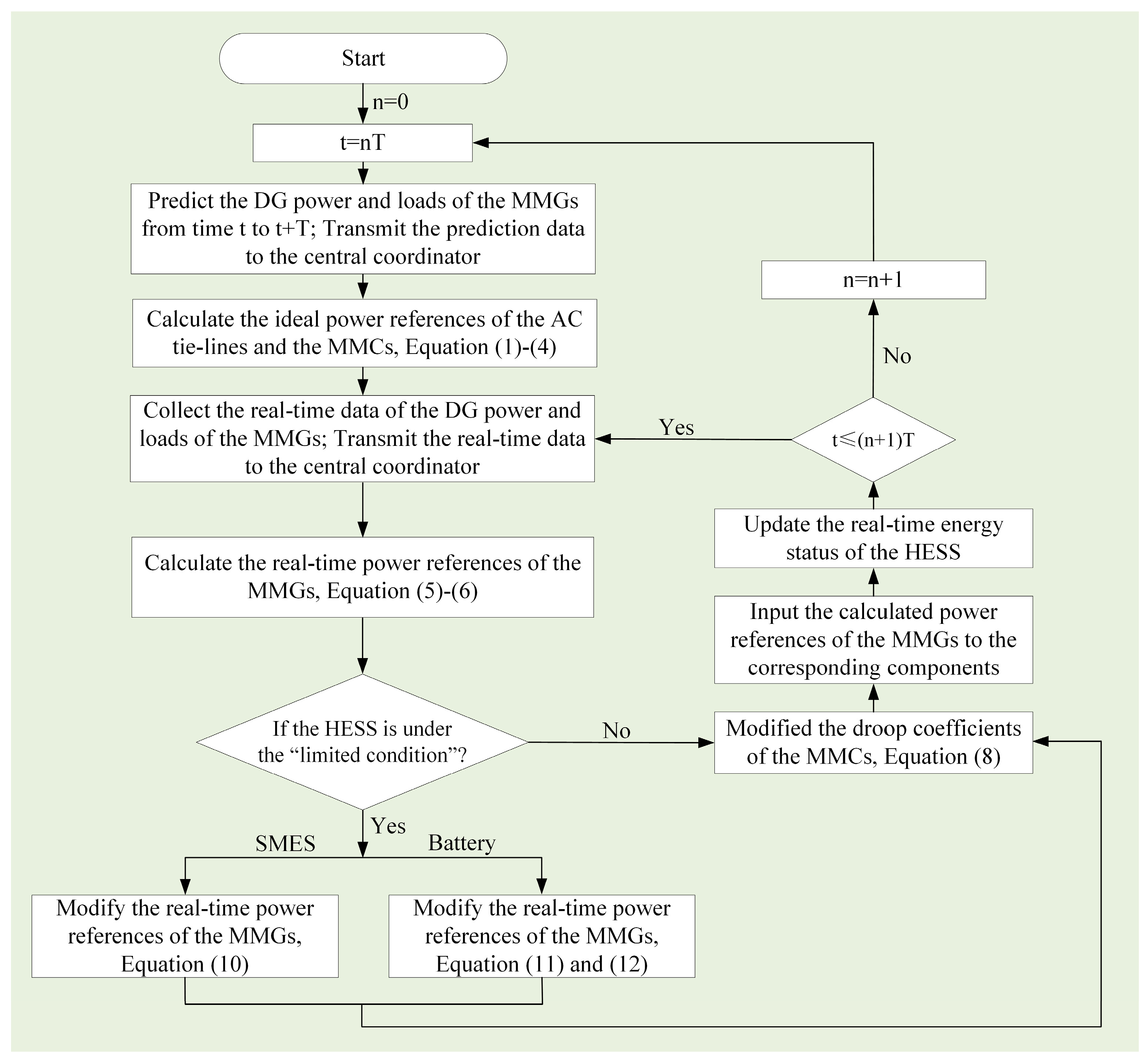
3.5. Algorithm of the Multi-Layer Coordinated Control Scheme
In
Section 3, the proposed multi-layer coordinated control scheme for the grid-connected MMGs is introduced. The control scheme consists of several procedures including the assignment of the AC tie-line power references, suppression of the power fluctuation, modification of the droop coefficients of the MMCs, and the adjustment of the power references during the “limited condition” of the HESS. The algorithm of the proposed multi-layer coordinated control scheme is illustrated in
Figure 5.
As is shown in
Figure 5, the ideal power references of the AC tie-lines and the MMCs are first calculated during every dispatch period based on the prediction of the DG power and loads. Then, the fluctuating power of the MMGs is calculated based on the real-time DG power and loads. The fluctuating power is compensated by the batteries and the SMES. Hence, the real-time power references of the MMGs are derived. Next, the status of the HESS is examined. If the HESS is under the “limited condition”, modification to the real-time power references of the MMGs is made. After that, the modified droop coefficients of the MMCs are calculated and the generated power references are transmitted to the corresponding components in the MMGs to eventually realize the function of the multi-layer coordinated control scheme.
4. Case Studies
The simulation model of a grid-connected MMGs is built in PSCAD/EMTDC. It is based on the demonstration project of MMGs in Sanli No.1 Junior High School (Guangxi, China) [
13]. Its architecture and configuration is as shown in
Figure 1. The simulation model is composed of three HUCC-based microgrids which are geographically close to each other. MG1 and MG2 are directly connected to the utility grid while the three microgrids are DC interconnected. Every sub-microgrid consists of a PV array, a WT, a battery, and local loads. MG3 also has a diesel generator to regulate its voltage and frequency. A SMES is centrally implemented to the DC network of the MMGs. The components of the sub-microgrids including the SMES and their nominal active power are listed in
Table 2.
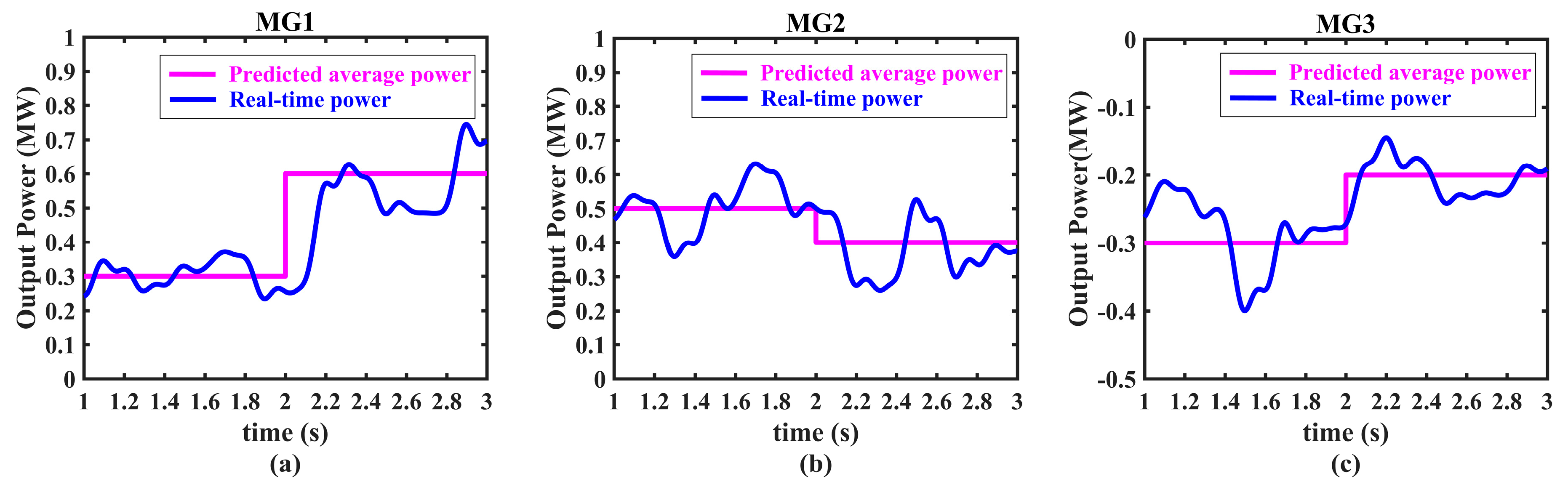
In order to highlight the effectiveness of the proposed multi-layer coordination control scheme while simplifying the simulation, the PV array and the WT in every sub-microgrid are controlled to work at the maximum power point, and they are considered as a whole along with the local loads. Their total power is referred to as the sub-microgrid output power. In the meantime, the power data is time-scaled considering that 10 min, which is the dispatch period, corresponds to 1 s of simulation and two consecutive dispatch periods are demonstrated in the simulation. The predicted average output power of the sub-microgrids and the real-time output power of the sub-microgrids that are adopted in the simulation are shown in
Figure 6.
The predicted average output power of MG1, MG2, and MG3 are calculated by Equations (1) and (2). During the first dispatch period, the predicted average output power of the three sub-microgrids are 0.3 MW, 0.5 MW, and −0.3 MW, respectively; during the second dispatch period, the predicted average output power of the three sub-microgrids change to 0.6 MW, 0.4 MW, and −0.2 MW, respectively. Meanwhile, the real-time output power of the sub-microgrids fluctuates around the predicted average output power. Since the proposed control scheme focuses on the optimized management and distribution of active power, the reactive power of the sub-microgrids are set to zero in the simulation. The main parameters of the simulation model are listed in
Table 3.
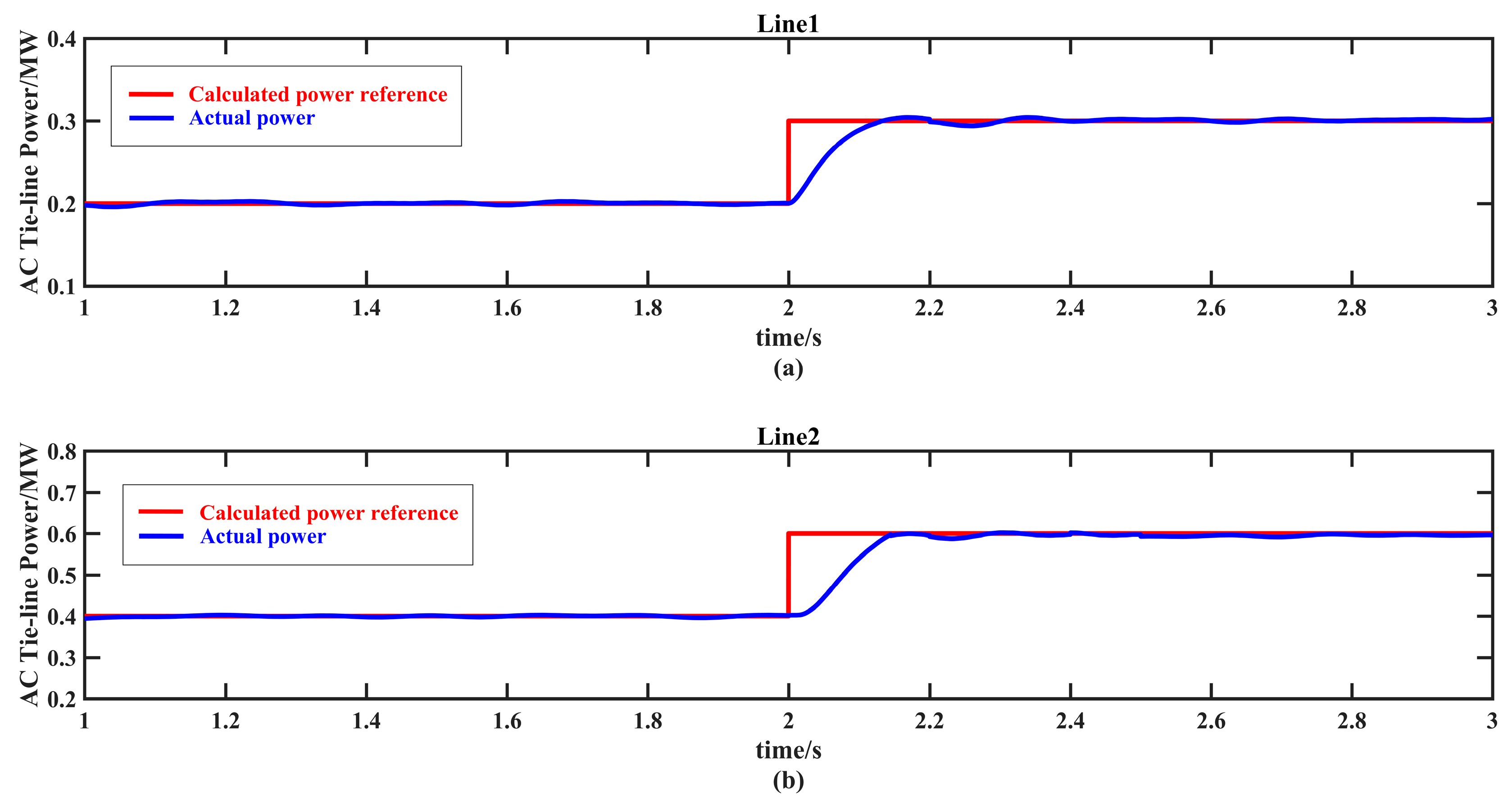
4.1. Normal Operation of the HESS
During the normal operation of the HESS, the batteries and the SMES suppress the power fluctuation of the MMGs coordinately as
Section 3.2 introduces and the real-time power references of the MMGs need no modification according to the algorithm in
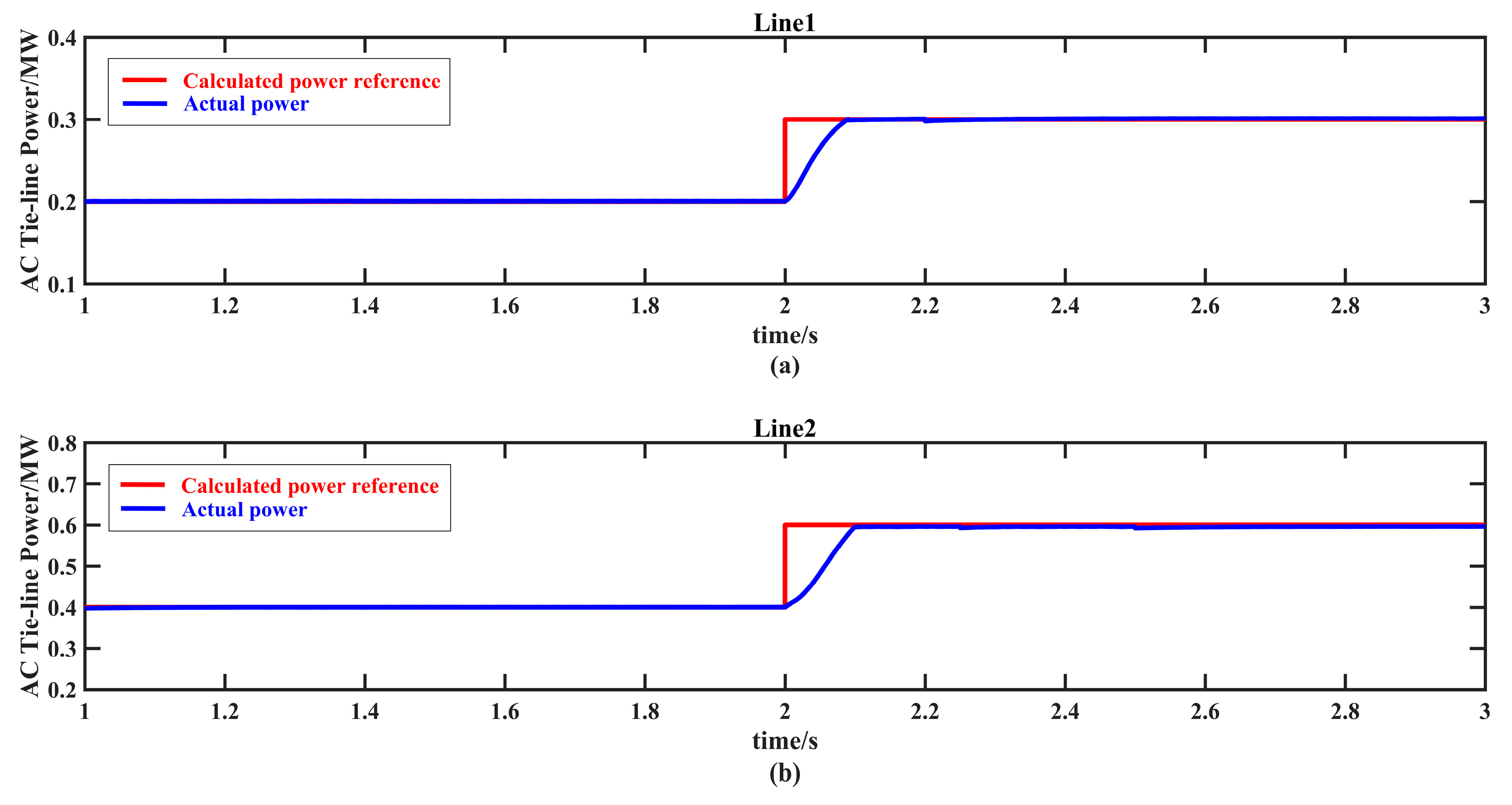
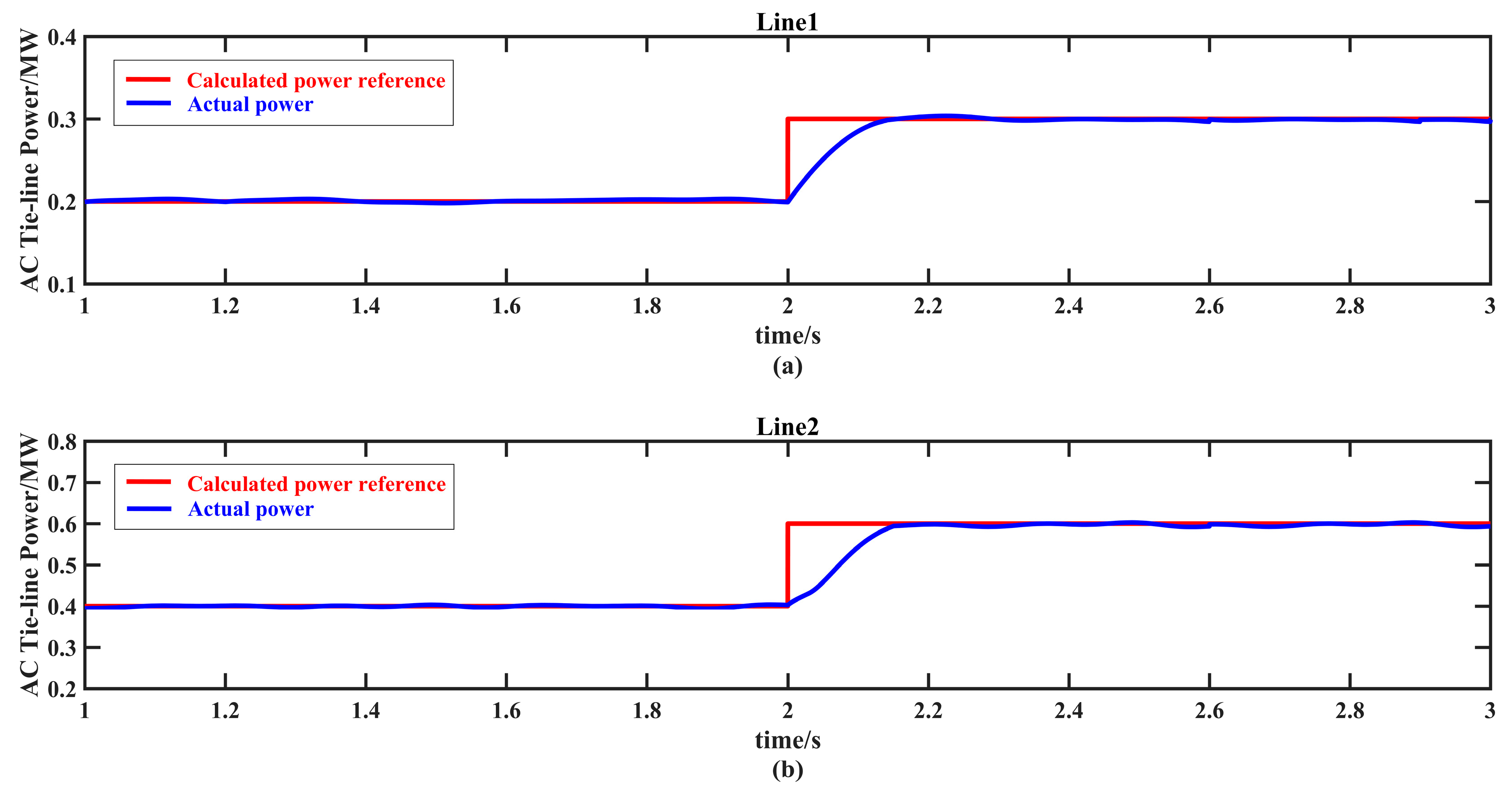
Figure 5. Since the ratio of the rated capacity of the two feeder transformers is 1/2, the ideal AC tie-line power references, which are also the real-time AC tie-line power references, are calculated according to Equation (3). During the first dispatch period, the calculated AC tie-line power references of Line1 and Line2 are 0.2 MW and 0.4 MW, respectively; during the second dispatch period, the calculated AC tie-line power references of Line1 and Line2 are 0.3 MW and 0.6 MW, respectively. The calculated AC tie-line power references and the actual AC tie-line power are both shown in
Figure 7.
As
Figure 7 shows, the actual power of the AC tie-lines track the calculated power references well during different dispatch periods. The control objective of optimizing the AC tie-line power as flat as possible is achieved. However, it should be noted that the actual power of the AC tie-lines deviate slightly from the calculated power references during the transition of different dispatch periods. This is due to the dynamic response characteristics of the MMC. Since there are relatively large variations in the calculated power references of the MMGs during different dispatch periods, it takes some time for the MMCs to dynamically track the new power references so as to re-distribute the power of the MMGs. According to the simulation, the actual AC tie-line power tracks the new power references quickly and smoothly during the transition of different dispatch periods owing to the fast dynamic response of the MMCs.
Table 4 presents the power deviations of the AC tie-lines, the load rates of the feeder transformers during different dispatch periods, and the power settling times of the AC tie-lines. The data validate the above analysis.
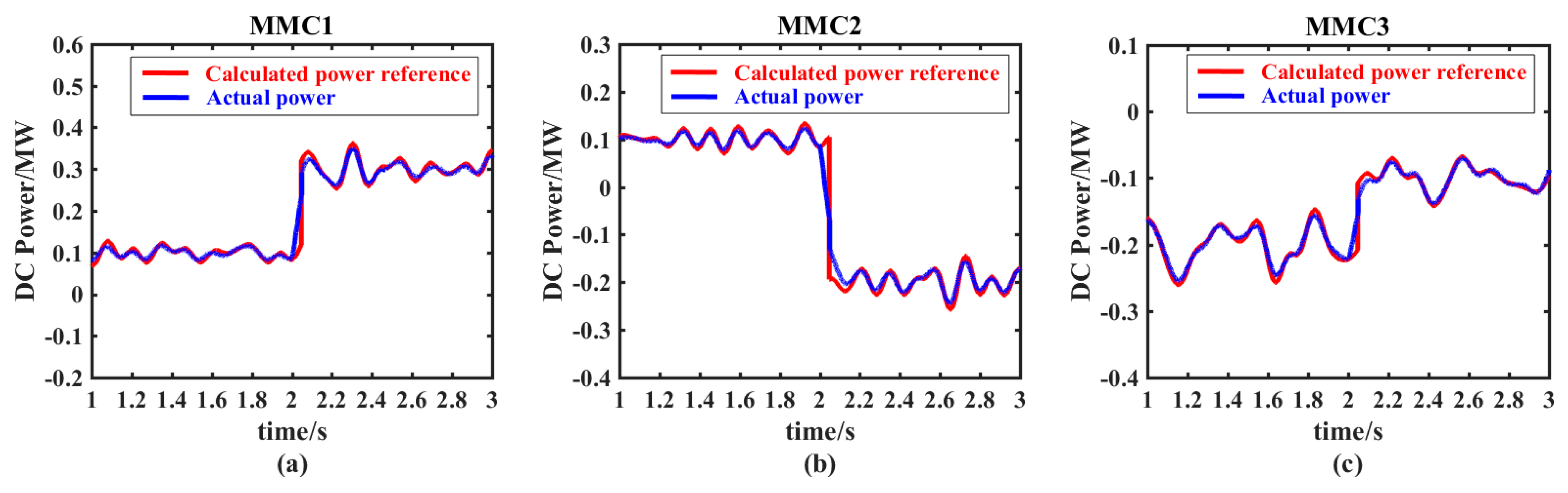
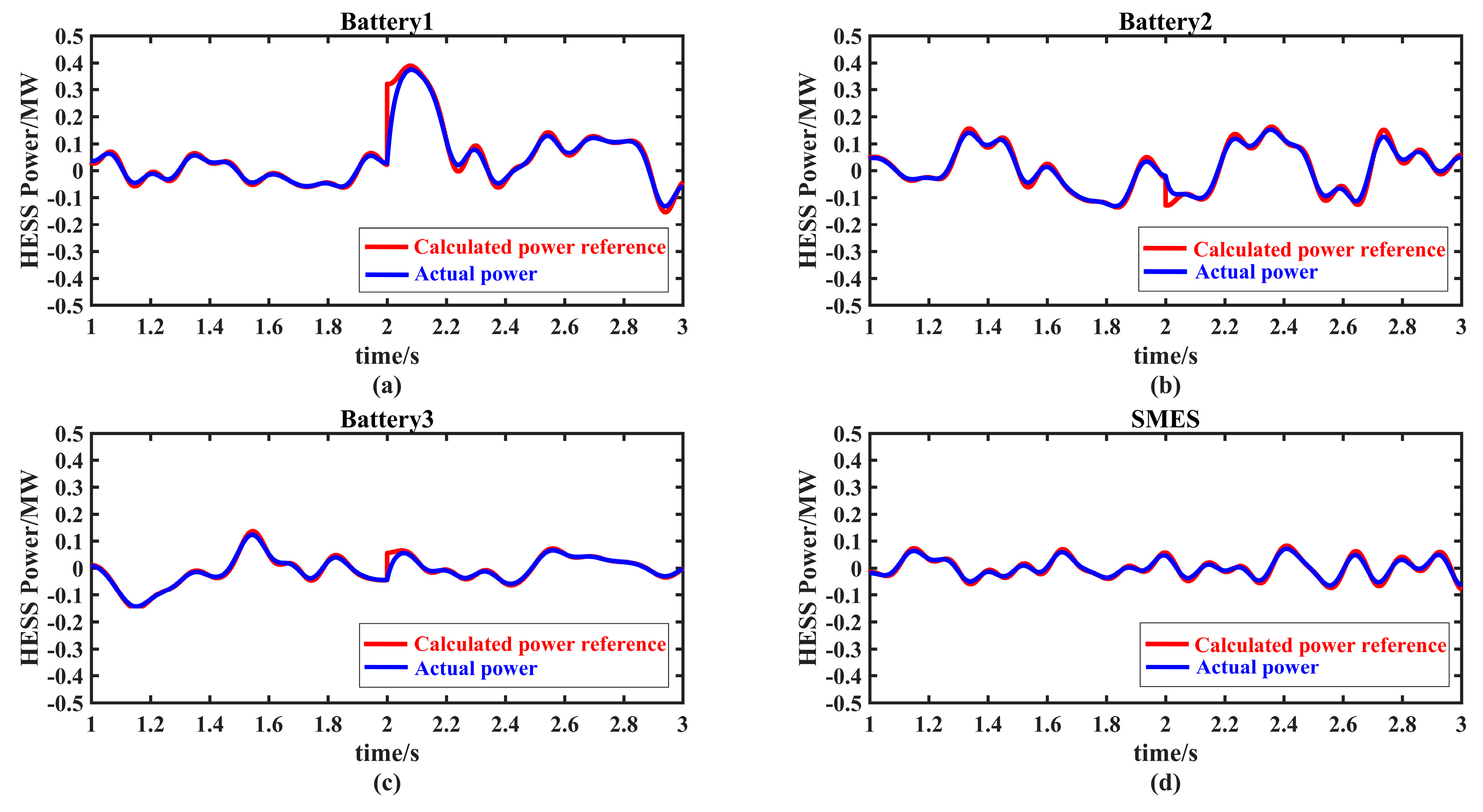
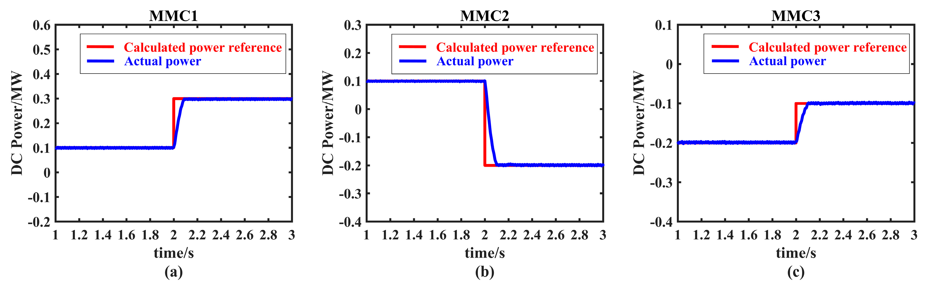
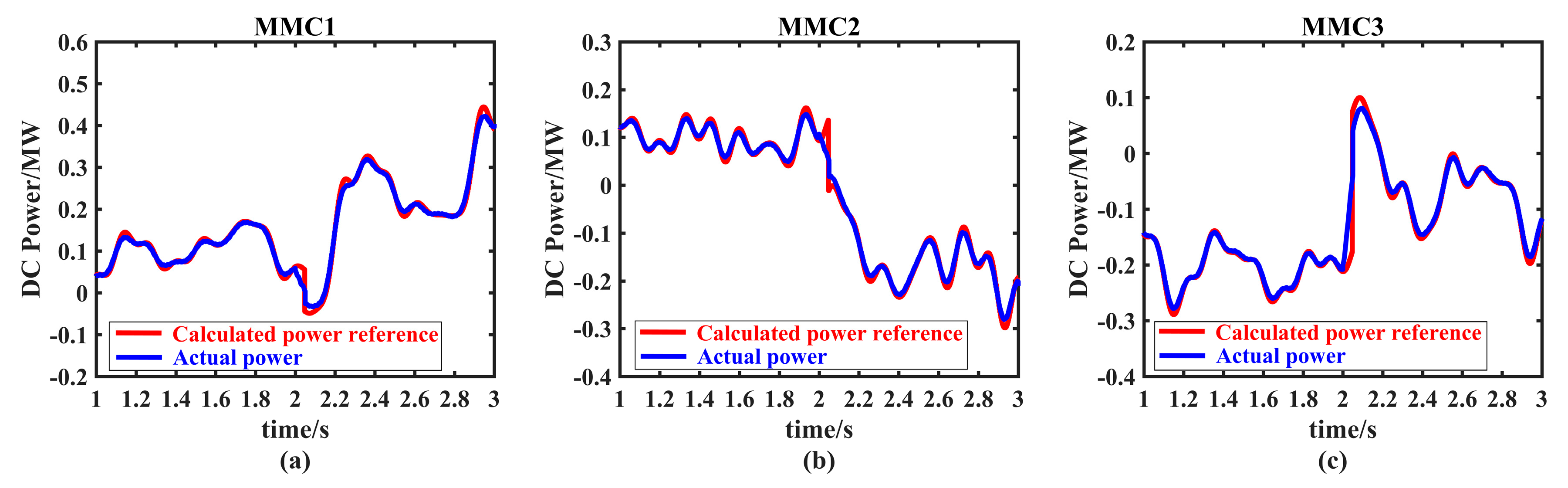
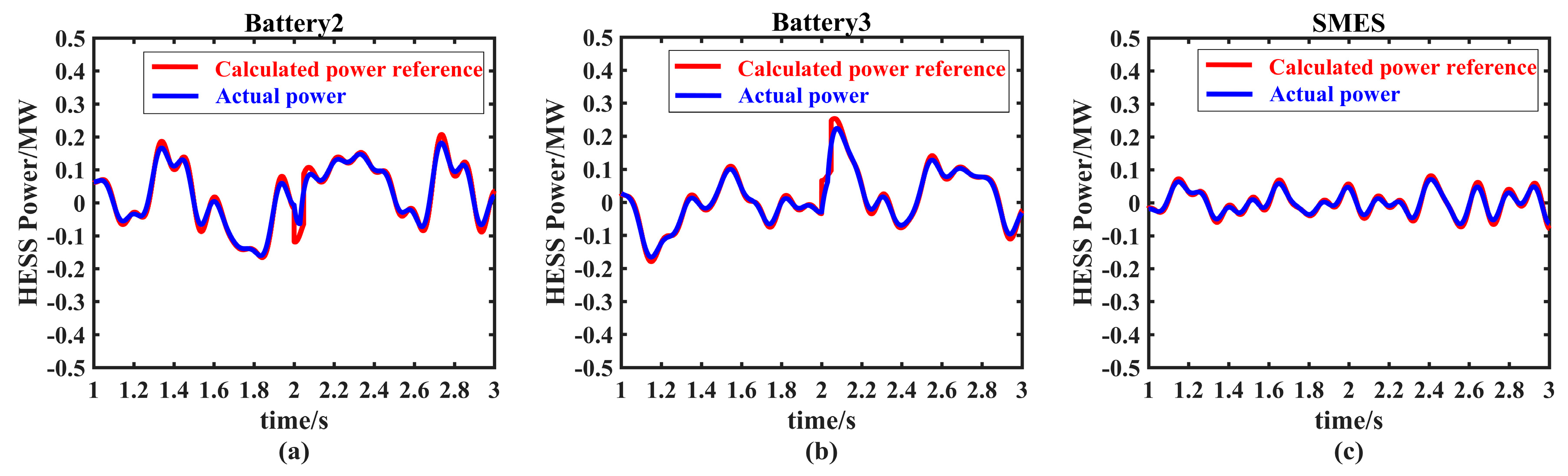
The proposed multi-layer coordinated control scheme relies on the coordination among the MMCs and the HESS. The calculated power references and the actual power of the MMCs and the HESS are shown in
Figure 8 and
Figure 9, respectively.
According to the proposed control scheme, the MMCs not only exchange power among the microgrids, but also transmit the high frequency fluctuating power of the sub-microgrids to the SMES for central suppression. At the same time, the batteries suppress the low frequency fluctuating power of the sub-microgrids locally. As
Figure 8 and
Figure 9 show, even though the power oscillates frequently and fast during the dispatch periods, the MMCs adaptively track the calculated power references via the adaptive droop control and the calculated power references of the batteries and the SMES are also well tracked in the simulation. It indicates that both the MMCs and the HESS work appropriately and effectively as the proposed control scheme requires. This is also verified by the power deviations of the MMCs and the HESS listed in
Table 4. As a result, flat AC tie-line power is achieved and the power fluctuation is suppressed owing to the effective coordination among the MMCs and the HESS.
4.2. Limited Condition of the HESS
4.2.1. Limited Condition of the SMES
When the SMES is under the “limited condition”, the SMES quits operation for self-protection and the high frequency fluctuating power of the sub-microgrids is suppressed locally by the batteries according to the compensation principles of the HESS introduced in
Section 3.4. The actual power of the AC tie-lines during the “limited condition” of the SMES is shown in
Figure 10. The calculated power references and the actual power of the MMCs and the HESS are shown in
Figure 11 and
Figure 12, respectively.
As
Figure 10,
Figure 11 and
Figure 12 show, the batteries suppress both the high frequency and the low frequency fluctuating power when the SMES quits operation. Hence the MMCs are only responsible for the power exchange among the sub-microgrids without having to deal with the high frequency fluctuating power. The MMCs and the batteries track the modified power references well so that the flat optimized AC tie-line power is maintained during the “limited condition” of the SMES.
Table 5 presents the operation indexes of the MMGs during the limited condition of the SMES. The above analysis is validated by the data.
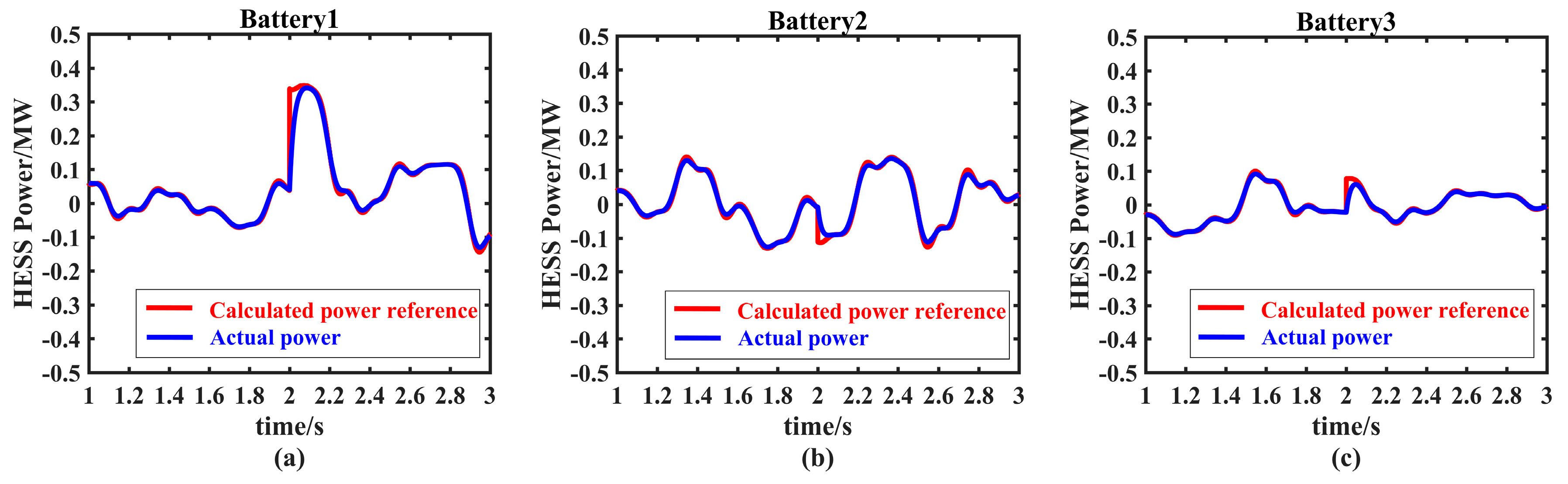
4.2.2. Limited Condition of the Battery
When the battery is under the “limited condition”, the battery quits operation for self-protection and its assigned power is compensated by the other two batteries according to their rated capacity, as is introduced in
Section 3.4. Take Battery1 for instance. Since Battery2 and Battery3 have the same rated capacity according to
Table 3, the assigned power of Battery1 is compensated equally by the two batteries. Accordingly, the power references of the MMCs are modified to facilitate the compensation process while the power reference of the SMES remains the same. The actual power of the AC tie-lines during the “limited condition” of Battery1 is shown in
Figure 13.
The calculated power references and the actual power of the MMCs and the HESS are shown in
Figure 14 and
Figure 15, respectively. As
Figure 13,
Figure 14 and
Figure 15 show, the modified power references of the MMCs and the HESS oscillate significantly during each dispatch period when Battery1 quits operation. But they are still tracked well by the MMCs and the HESS as the proposed control scheme requires. Consequently, the flat optimized AC tie-line power is maintained.
Table 6 presents the operation indexes of the MMGs during the limited condition of Battery1, which validates the above analysis. In addition, more simulations have been done regarding different batteries that are under the “limited condition” and batteries of different rated capacity ratio. The validity of the proposed control scheme is still verified.
Besides the simulation presented in
Section 4, numerous simulations with varied parameters have been done and the effectiveness of the proposed multi-layer coordinated control scheme has been proved. The MMCs and the HESS coordinate well with each other to distribute power among the sub-microgrids as required and suppress the power fluctuation. As a result, the coordination mechanism among the sub-microgrids and the HESS is established and the AC tie-line power of the MMGs is optimized as flat as possible, which eventually improves the operation friendliness of the MMGs both to the utility gird and the sub-microgrids.


