Article

Optimization Strategy of SVC for Eliminating Electromagnetic Oscillation in Weak Networking Power Systems

1
State Grid Sichuan Electric Power Research Institute, Chengdu 610041, China
2
School of Electrical Engineering, Beijing Jiaotong University, Beijing 100044, China
*
Author to whom correspondence should be addressed.
Energies 2019, 12(18), 3489; https://doi.org/10.3390/en12183489
Submission received: 9 August 2019 / Revised: 6 September 2019 / Accepted: 6 September 2019 / Published: 10 September 2019

Abstract

:
The central Tibet AC interconnection project (CTAIP), which connects the Tibet power grid and the Sichuan power grid through a long distance transmission line of more than 1400 km, has a significant problem of voltage regulation. In order to improve the voltage regulation performance, six sets of ±60 Mvar static VAR compensators (SVC) were installed in the CTAIP. However, the SVCs may lead to electromagnetic oscillation below 50 Hz while improving voltage regulation capability. In this paper, the electromagnetic oscillation modes and the sensitivity of control parameters of SVC are analyzed. Then, the characteristics and influencing factors of the oscillation are discussed. It was found that there is an inherent electromagnetic oscillation mode below 50 Hz in the ultra-long distance transmission system. The employ of SVCs weaken the damping of this mode. Large proportional gain and integral gain (PI) parameters of SVCs can improve the voltage regulation performance, but weaken the electromagnetic oscillation mode damping. Therefore, a suppression method based on SVC PI parameters optimization is proposed to damp the oscillation. The essential of this method is to use the rising time of voltage response and setting time of SVCs as performance indicators of voltage regulation, and take the damping level of the electromagnetic oscillation mode as the performance index of SVC electromagnetic oscillation suppression ability. Combining the two indicators to form a comprehensive optimization index function, an intelligent optimization algorithm is applied. The process of SVC parameter optimization and the steps of multi-SVC parameter optimization in large power grids is proposed. Finally, PSCAD and real-time digital simulation (RTDS) simulation results verified the correctness of the proposed method. The optimization strategy was applied to CTAIP. The artificial grounding short circuit experimental results proved the effectiveness of the proposed strategy.

1. Introduction

The central Tibet AC interconnection project (CTAIP) connects the central Tibet, Changdu, and Sichuan power grids of China. It has a long tie-line of more than 1400 km. Due to the long tie-line and its weak connection, the short circuit current of 500 kV buses is only 3–5 kA, and the reactive power and voltage regulation ability is extremely weak. In order to improve the voltage regulation performance of the interconnected system, six sets of ±60 Mvar static VAR compensators (SVC) were installed in the CTAIP. Due to the special network structure and the large capacity of SVCs, a kind of electromagnetic oscillation phenomenon with an oscillation frequency less than 50 Hz, which is similar to the subsynchronous oscillation, was observed through electromagnetic transient simulation.
In fact, the electromagnetic oscillation is one of the typical problems in power electronized power systems [1,2]. In the point view of oscillation frequency, the oscillation phenomenon in CTAIP is similar to the oscillation caused by subsynchronous control interaction (SSCI) [3,4]. There has been a large number of studies focused on SSCI. It has been pointed out in [5] that a power system stabilizer may deteriorate the subsynchronous oscillation mode damping of power systems. Reference [6] shows the subsynchronous oscillation of turbo-generators caused by HVDC. Subsynchronous resonance with VSC-based HVDC transmission systems was studied in [7]. Subsynchronous torsional interaction with power electronic converters was studied in [8]. Constant power load based on power electronics causing an oscillation was found in [9]. Subsynchronous oscillation caused by a wind farm was discussed in [10,11]. Reference [12] pointed out that the control interaction between a D-PMSGs-based wind farm and SVCs leads to sub-synchronous oscillation. However, there are very few reports of electromagnetic oscillation caused by SVCs. In [13], the phenomenon of 14 Hz oscillation in the central Tibet power grid caused by SVCs was introduced. However, the mechanism of oscillation is not clear yet. In [14], a ultra-low frequency oscillation and suppression method in the Central Tibet and Sichuan power grids was introduced, but it did not involve electromagnetic oscillation. To suppress the oscillation, additional damping controllers are often used for low frequency oscillation, while less research has been carried out on the suppression of electromagnetic oscillation. PSSs and SVC damping controllers were employed for suppressing local and inter-area low frequency oscillation in [15]. In [16], an adaptive neuro-fuzzy inference system-based controller was proposed for controlling the reactive power provided by static var compensator to damp inter-area oscillations. Reference [17] proposed a new time delayed controller to damp inter-area oscillations. Reference [18] studied the location and optimal capacity of SVCs. However, the location of SVC installation in this paper was fixed, and this method is not applicable to the problem to be studied in this paper. In [19], coordinated control of SVCs and TCSCs for voltage profile improvement employing particle swarm optimization was proposed, but oscillation suppression was not discussed. A novel modified fruit fly optimization algorithm combined with probabilistic sensitivity indices was proposed to coordinate and optimize SVC damping controller parameters to enhance the power system stability of the wind farm cluster in [20], but the PI control parameters of SVCs were not involved. In practice, the PI parameters of SVCs are decreased to eliminate the oscillation. It should be noted that although the reduction of the PI parameters increases the damping and suppresses the oscillation, the voltage regulation ability is weakened, which is very important in a weak networking power system such as CTAIP. However, there is no systematic method to optimize the PI parameters of SVCs considering both the electromagnetic oscillation suppression and voltage regulation capability.
In this paper, the characteristic and influencing factors of the electromagnetic oscillation are discussed. Based on it, an optimization strategy of SVC is proposed, considering both the suppressing of oscillation and voltage regulation capability. Firstly, the main oscillation modes are computed. Then the reactive power regulation performance of SVC is computed. After that, the optimization of PI parameters for SVC is implemented with an objective function considering both damping ratio improvement and the dynamic performance of the SVC. The features of this strategy are summarized as follows:
(1)
A quantitative method is provided for evaluating the influence of SVC on electromagnetic oscillation modes.
(2)
The contradiction between reactive power regulation ability and electromagnetic oscillation suppression ability of the SVC is revealed, which provides a basis for the definition of a comprehensive optimization objective function.
(3)
The performance criteria considering the damping characteristic and reactive performance of the SVC provides a new way to optimize PI parameters aiming at minimizing the negative effects of the SVC.
(4)
The process of SVC parameter optimization and the steps of multi-SVC parameter optimization in large power grid are proposed.
Finally, the proposed systematic strategies were applied to CTAIP. Numerical simulations under different typical faults with PSCAD and real-time digital simulation (RTDS) verified the correctness of the proposed method. The proposed strategy has been applied in practical engineering. The effectiveness of the proposed strategy was proved by the artificial grounding short experimental results of CTAIP.
This paper is structured as follows. The basic characteristics of CTAIP and electromagnetic oscillation below 50 Hz are presented in Section 2. Section 3 discusses the key influencing factors of electromagnetic oscillation mode, and the contradiction between oscillation suppression and reactive power regulation is pointed out. A systematic optimization strategy of SVC PI parameters, considering both the electromagnetic oscillation suppression and reactive power regulation, is proposed in Section 4. In Section 5 and Section 6, the effectiveness of the proposed strategy is verified by the simplified system and the CTAIP, respectively. Finally, conclusions are drawn in Section 7.

2. Problem Formulation

In this section, the CTAIP and the risk of electromagnetic oscillation caused by SVCs are introduced.

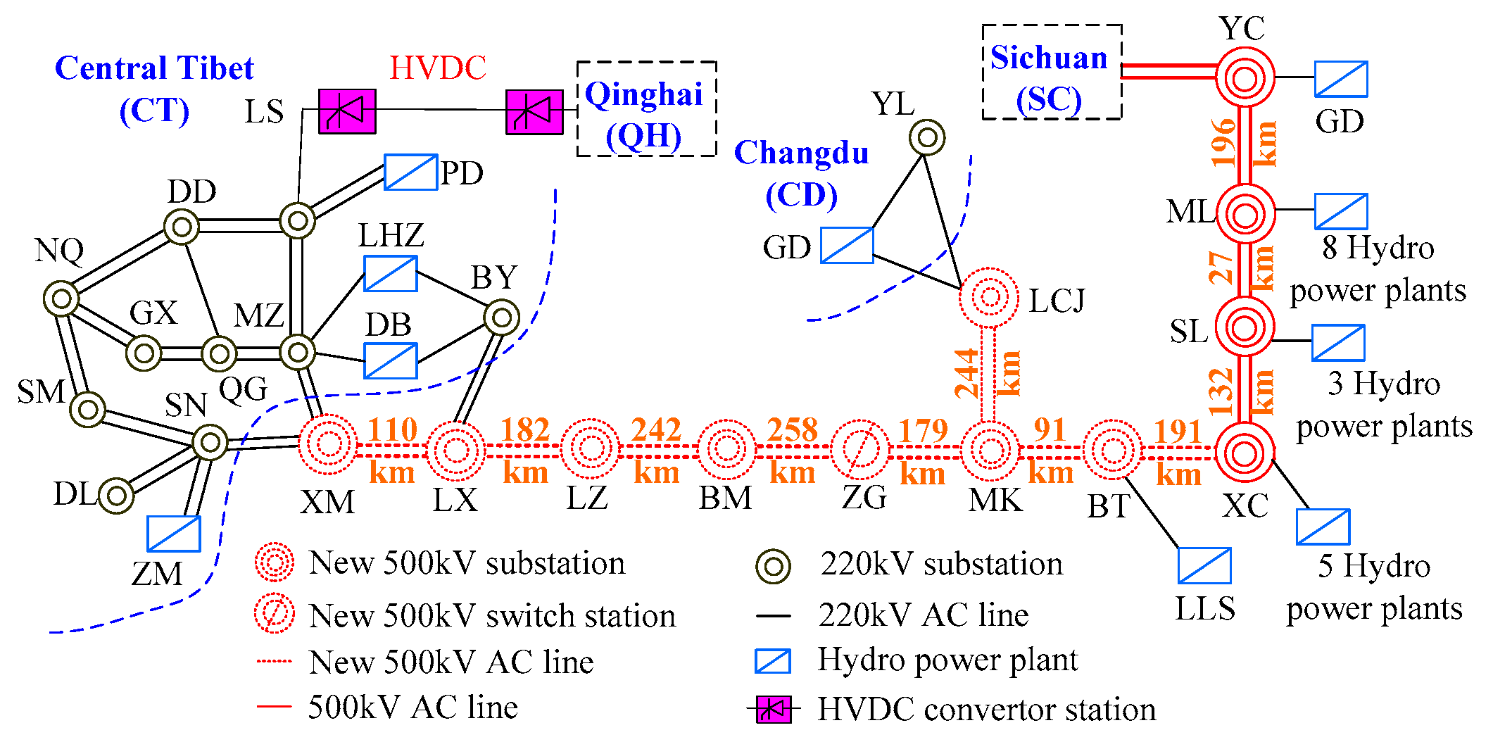
2.1. A Brief Introduction of CTAIP

As shown in Figure 1, there are seven 500 kV substations, and one 500 kV switch station in the CTAIP. The central Tibet, Changd, u and Sichuan power grids form a synchronous interconnected grid through this project.
The major features of the project are summarized as follows:
(1)
The length of the tie-line reaches 1497 km, and there is no power supply on the transmission lines.
(2)
The maximum short circuit current of 500 kV bus is only 5 kA. In substation LZ, it is only 3–4 kA.
The reactive power and voltage regulation capability of the project is very poor due to the above characteristics. As shown in Figure 2, the voltage fluctuation of the 500 kV system caused by the switching on and off of a single set of low-voltage reactor (60 Mvar) reaches 23 kV during the system charging start-up process.
In order to control the voltage of the interconnected system, two ±60 Mvar TCR+FC type SVCs are installed in LX, BM, and MK substations, respectively.

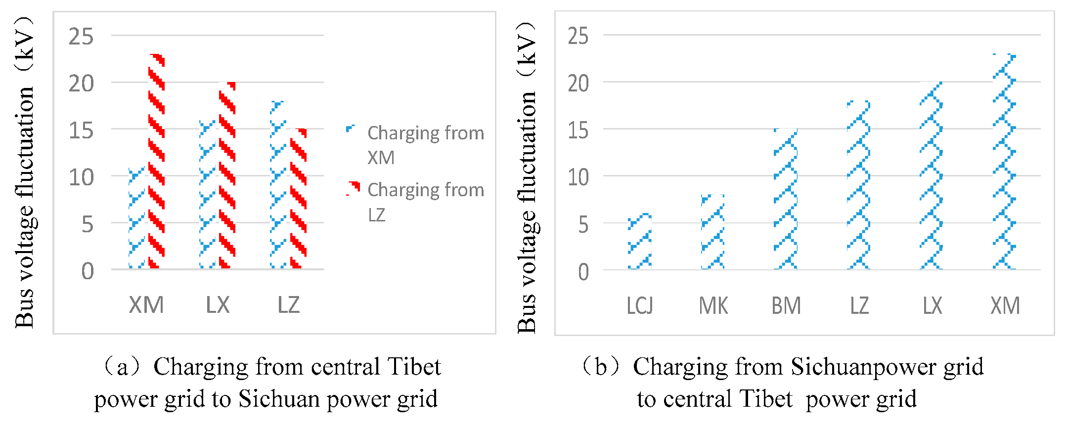
2.2. Electromagnetic Oscillation of CTAIP

SVCs are required to provide fast support of reactive power with relatively large PI parameters. However, excessive or inappropriate SVC PI parameters may cause electromagnetic oscillations below 50 Hz. Or in the case of failure resulting in the system short-circuit capacity reduction, SVCs may cause instable electromagnetic oscillation. A typical oscillating waveform is shown in Figure 3.

3. Characteristics of Electromagnetic Oscillation Induced by SVCs

In order to explain the principle and key influence factors of the electromagnetic oscillation phenomenon in the CTAIP, a simplified system is used. The eigenvalue of electromagnetic oscillation is calculated. The influence of line length, system equivalent impedance, capacity of SVCs and SVC control parameters on the electromagnetic oscillation mode is discussed.

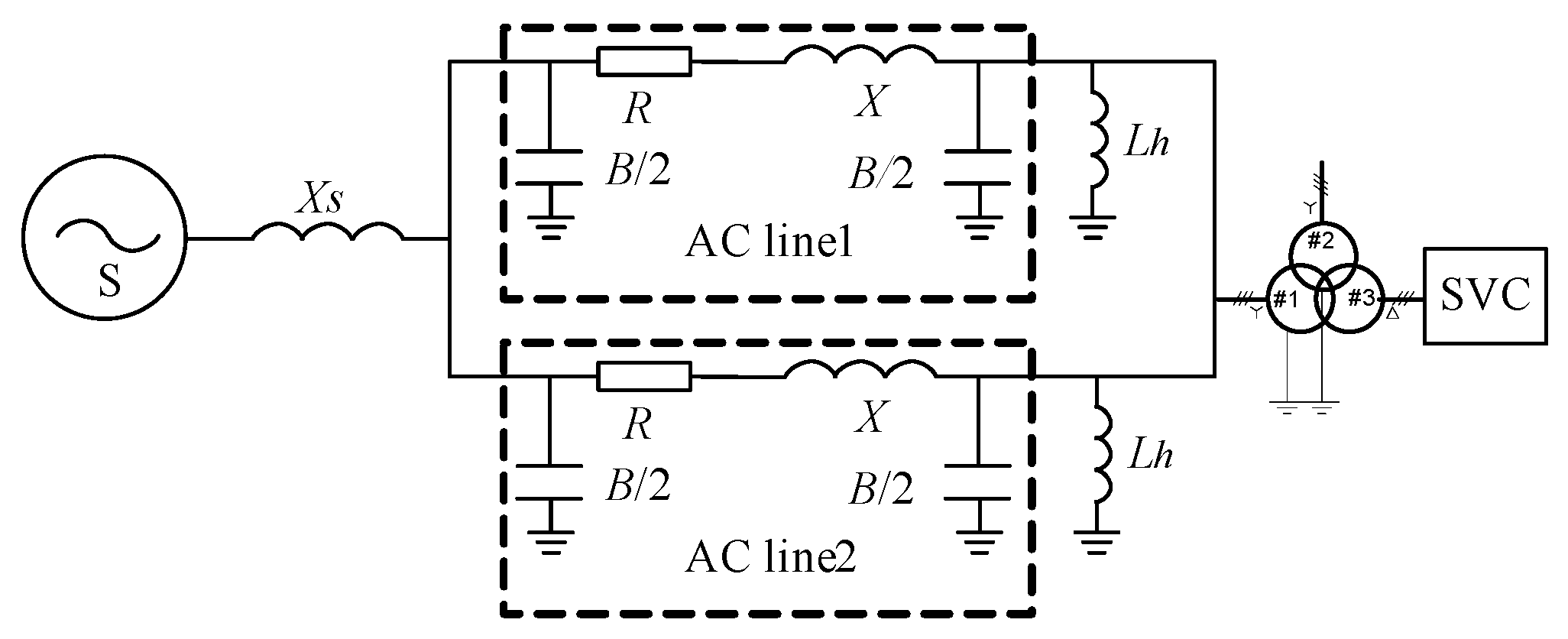
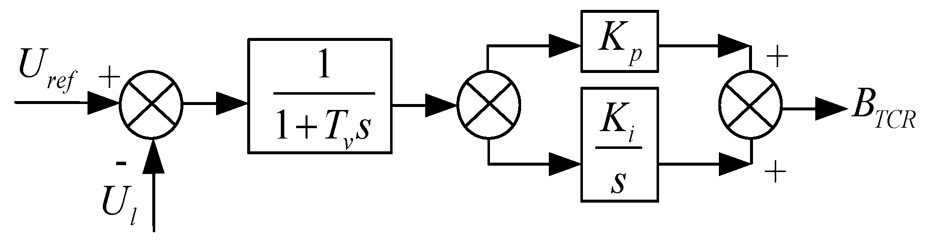
3.1. Simplified Model

Single power series two lines, with the SVC system model is shown in Figure 4. Xs is the impedance of power supply. R, X and B are line resistance, reactance and admittance, respectively. Lh is the high voltage shunt reactor, of which the compensation is considered within 70%. Transformer capacity is 750 MVA with rated voltage of 550/242/36 kV. The primary device parameters are shown in Table 1.

3.2. Electromagnetic Oscillation Mode Calculation

The equation of inductance and capacitance under Park’s transformation can be expressed as
{ X ω 0 s i d q = X [ 0 1 1 0 ] i d q + u d q B ω 0 s u d q = B [ 0 1 1 0 ] u d q + i d q
where, i d q = [ i d i q ] T ,   u d q = [ u d u q ] T , s is the differential operator. id, iq are the d axis and q axis components of the current, respectively. ud, uq are the d axis and q axis components of the voltage, respectively. ω0 is reference frequency. X is inductance, B is admittance.
The primary circuit and simplified circuit of a TCR+FC type SVC is shown in Figure 5. TCR can be equivalent to a variable reactor and the filter is equivalent to a series branch of inductor and capacitor.
A simplified control block diagram of SVC is shown in Figure 6.
State space model of the control block diagram is as follows:
{ s x = k i ( U r e f U l ) s B T C R = 1 T v x 1 T v B T C R + k p T v ( U r e f U l )
where, BTCR is the admittance of TCR. Tv is time constant of inertial link. kp is proportional gain, ki is integral gain. Uref, Ul are reference voltage and actual voltage of the SVC, respectively. s is the differential operator, x is the state variable.
Since the filter can be decomposed into inductor and capacitor, it can be modeled by the method shown in Equation (1). The TCR model under simplified circuit can be expressed as
{ s x = k i ( U r e f U l ) s B T C R = 1 T v x 1 T v B T C R + k p T v ( U r e f U l ) 1 ω 0 s I T C R = [ 0 1 1 0 ] I T C R B T C R U l d q
where, I T C R = [ I T C R d I T C R q ] T , U l d q = [ U l d U l q ] T , U l = U l d 2 + U l q 2 . ω0 is reference frequency. ITCRd, ITCRq are the d axis and q axis components of the TCR current respectively. Uld, Ulq are the d axis and q axis components of the SVC voltage, respectively.
Let all state variables constitute the phasor y, the linearized model of the system including inductors, capacitors and SVC is
M Δ y = λ N Δ y
where, M is coefficient matrix of the linearized model of the system. N is a diagonal matrix, of which the diagonal element is 1 or 0. The diagonal element of N corresponds to a differential equation is 1, and corresponds to an algebraic equation is 0. λ is a complex number, which is also known as the generalized eigenvalue of matrix pair (M, N). The electromagnetic oscillation mode of the power system furnishing with SVC can be calculated by solving this generalized eigenvalue problem. The eigenvalues can be expressed as
λ = σ ± j ω
where, σ is attenuation factor. ω is the frequency of electromagnetic oscillation mode. The oscillation frequency f and damping ratio ζ are
{ f = ω 2 π ξ = σ σ 2 + ω 2
It is difficult to obtain an analytical solution because of the high order of the equation of the equivalent system, so numerical solutions are chosen.

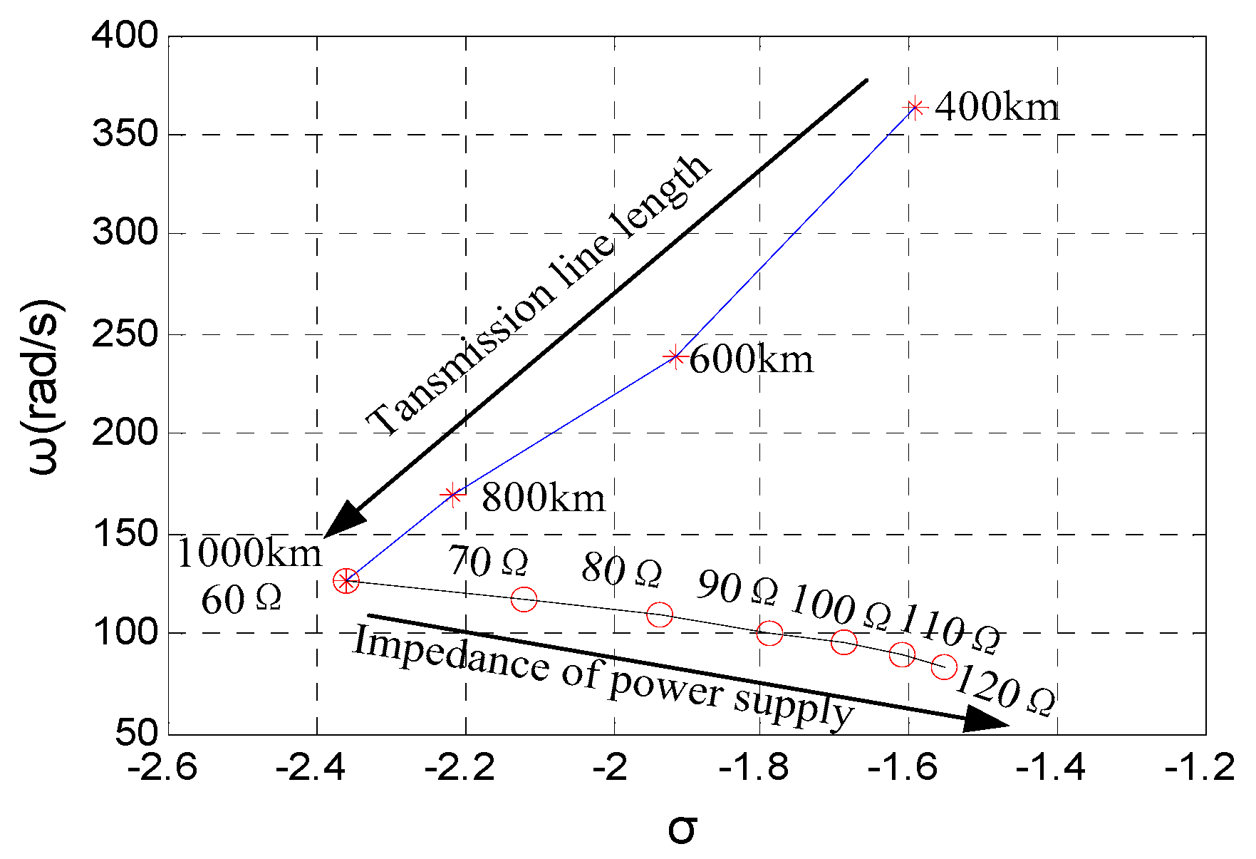
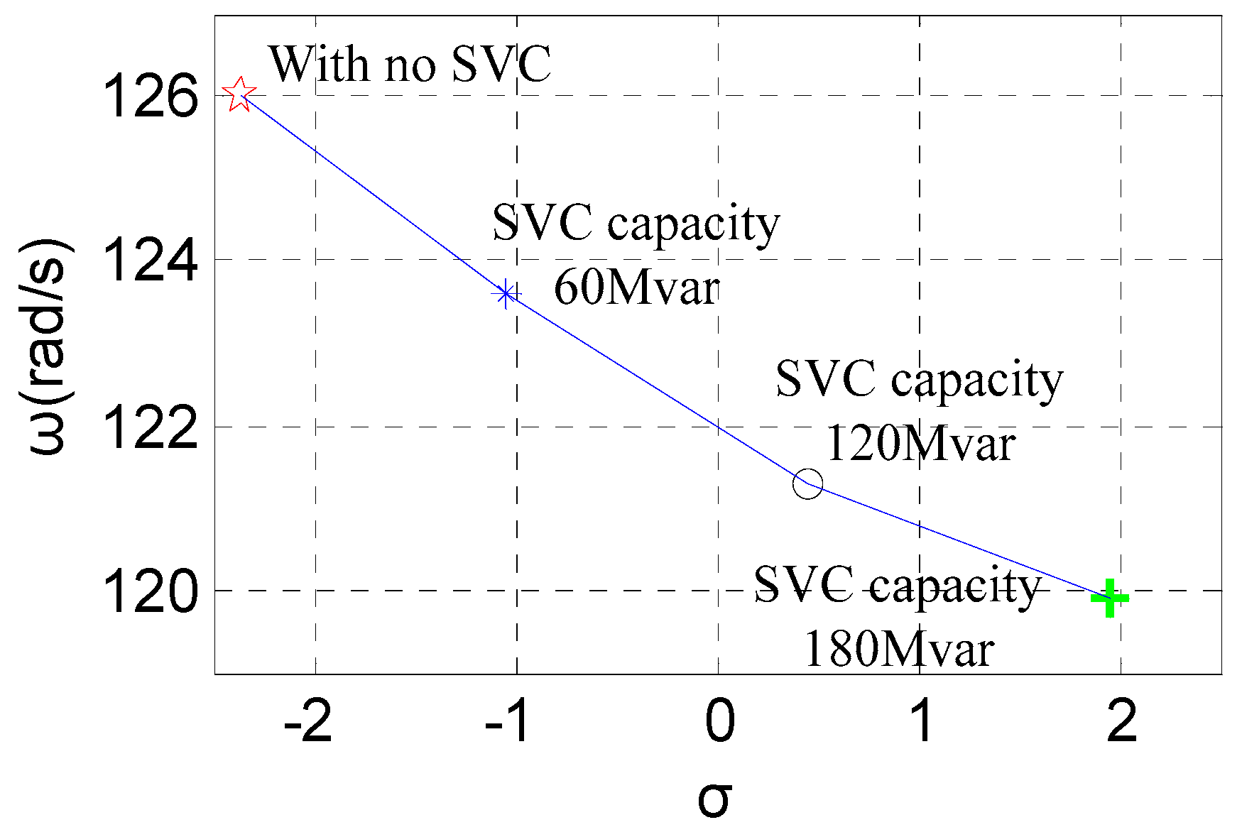
3.3. Key Influence Factors of the Electromagnetic Oscillation

The inherent oscillation mode of the system is shown in Figure 7. In the absence of an SVC, with the increase of line length, the frequency of electromagnetic oscillation gradually decreases. When the line length is longer than 500 km, the electromagnetic oscillation mode with a frequency below 50 Hz occurs. With the increase of system equivalent impedance, the frequency and attenuation coefficient of the electromagnetic oscillation gradually decrease.
The variation trend of the eigenvalue of the main electromagnetic oscillation mode with different capacities of SVCs is shown in Figure 8. As shown in Figure 8, the access of SVCs decrease the damping of the electromagnetic oscillation mode. The larger the SVC capacity, the greater the negative impact on the electromagnetic oscillation mode.
If line tripping, generator tripping, and other faults occur, the equivalent impedance of the system increases. The rapid reactive power regulation of SVC may lead to electromagnetic oscillation.

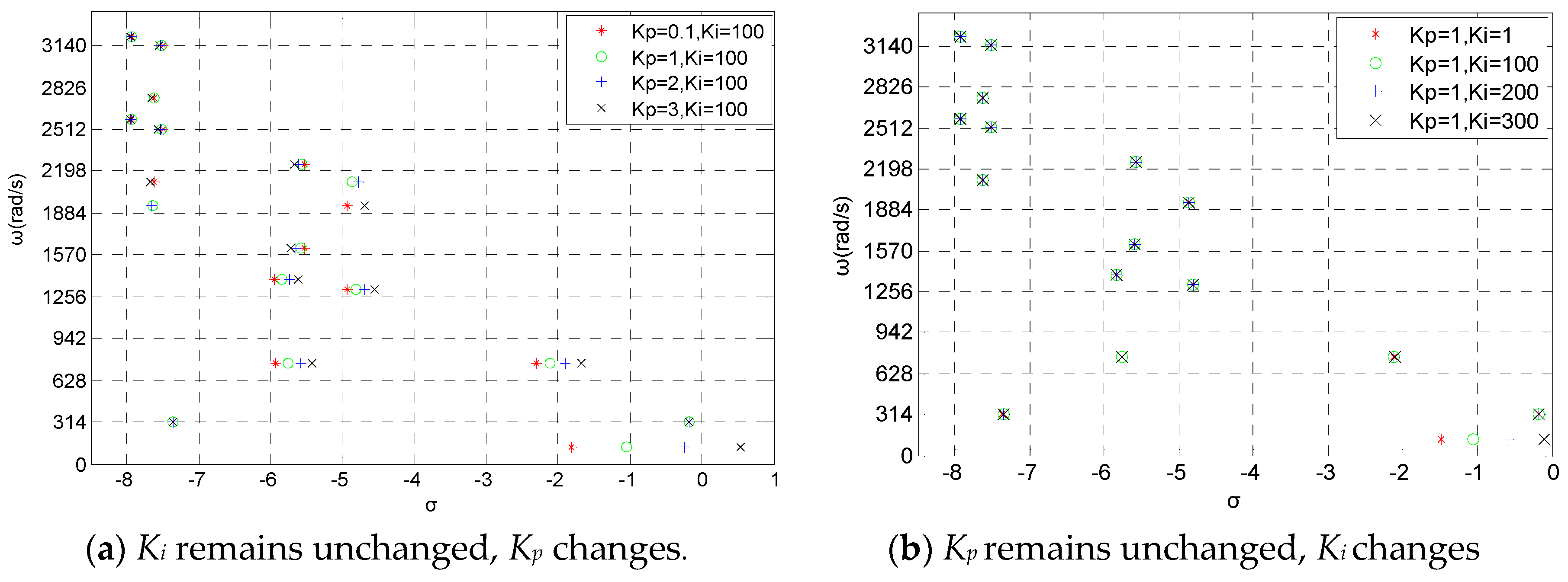
3.4. Sensitivity of SVC Control Parameters to Electromagnetic Oscillation

The variation trend of eigenvalues of the electromagnetic oscillation mode with SVC PI parameters is shown in Figure 9.
As shown in Figure 9a, when ω is less than 1570 rad/s (f < 250 Hz), with the increase of Kp, the eigenvalues of the electromagnetic mode move to the right side of the complex plane. Kp has the greatest influence on the oscillation mode when ω is less than 314 rad/s (f < 50 Hz). When ω is greater than 1570 rad/s (f > 250 Hz), Kp has almost no effect on the electromagnetic oscillation mode.
As shown in Figure 9b, when ω is greater than 314 rad/s (f > 50 Hz), Ki has almost no effect on electromagnetic oscillation mode. When ω is less than 314 rad/s (f < 50 Hz), with the increase of Ki, the eigenvalues of the electromagnetic mode move to the right side of the complex plane.
When ω equals 314 rad/s (f = 50 Hz), the PI parameters of SVC has no effect on the oscillation mode.
According to the principle of TCR, the thyristor is triggered twice in a power cycle. The output sampling rate of TCR reaches 100 Hz. Thus, according to Shannon’s sampling theorem, for oscillation modes with angular frequencies greater than 314 rad/s, it is impossible for a TCR control strategy to affect them. However, it is mathematically difficult to consider this spectrum truncation phenomenon in a small signal analysis model. We find in Figure 9 that oscillation modes with angular frequencies greater than 50 Hz are influenced by Kp. This is actually not true. The following part of this paper focuses on the oscillation modes with angular frequencies smaller than 314 rad/s, so this defect of this model does not affect this study.

3.5. Effect of SVC Control Parameters on Reactive Power Regulation Performance

Based on the foregoing analysis, in order to suppress electromagnetic oscillation, it is necessary to reduce Kp and ki. However, the reactive power and voltage regulation capability of the SVC will be weakened. As shown in Figure 10, the performance of electromagnetic oscillation damping levels and reactive power regulation are contradictory. Therefore, it is necessary to find an SVC control parameter optimization method which can suppress electromagnetic oscillation and maintain enough reactive power regulation performance of the SVC.

4. Parameter Optimization Strategy

In this section the reactive power regulation performance index and the electromagnetic oscillation suppression capability index are proposed. A comprehensive optimization objective function with two objectives is proposed, and the process of SVC parameter optimization is presented.

4.1. Reactive Power Regulation Performance index

A step signal with certain amplitude is applied to the voltage reference of the SVC control system (it is not advisable to trigger the limiting link of the SVC controller). The SVC reactive power or admittance response curve can be obtained by the time domain simulation.
In order to quantify its voltage regulation performance, an index J1(K) is proposed to indicate the reactive power regulation performance of SVC.
J 1 ( K ) = k 1 T 0.9 + k 2 T s
where, J1(K) is voltage regulation performance index function of SVC under PI parameters vector K = [kp, ki]. T0.9 indicates the rise time from voltage differential exceeds voltage dead zone to SVC output reactive power or admittance reaches 90% target value. Ts indicates the time from voltage differential exceeds voltage dead zone to SVC output reactive power or admittance reaches stability. k1 represents the weight coefficient of rise time, and k2 represents the weight coefficient of settling time. k1 and k2 can be set to 1. k1 and k2 can be set to 1.

4.2. Electromagnetic Oscillation Suppression Capability Index

The index function reflecting the electromagnetic oscillation suppression ability of the SVC can be defined as
{ J 2 ( K ) = n = 1 n = n max p n 1 ξ n ( f n ) f n < f max < 50 Hz ξ n ( f n ) > 0
where, J2(K) is the electromagnetic oscillation suppression capability index. ξn, fn is the damping ratio and the frequency of nth oscillation mode, respectively. fmax is the highest oscillation frequency concerned. Because the TCR trigger frequency is 100 Hz, the frequency of oscillation caused by the SVC is lower than 50 Hz according to Shannon’s sample theorem. pn is the weight coefficient of each oscillation mode.

4.3. Optimization Objective Function

The objective function of parameter optimization is defined as
J ( K ) = m 1 J 1 ( K ) + m 2 J 2 ( K )
where, J(K) is the comprehensive evaluation index function of SVC reactive power regulation performance and electromagnetic oscillation suppression capability. m1, m2 represent the weight of the reactive power regulation performance index and the weight of electromagnetic oscillation suppression index of the SVC, respectively. Considering the suppression of electromagnetic oscillation as the main factor, m1 can be set to 1 and m2 can be set to 2.

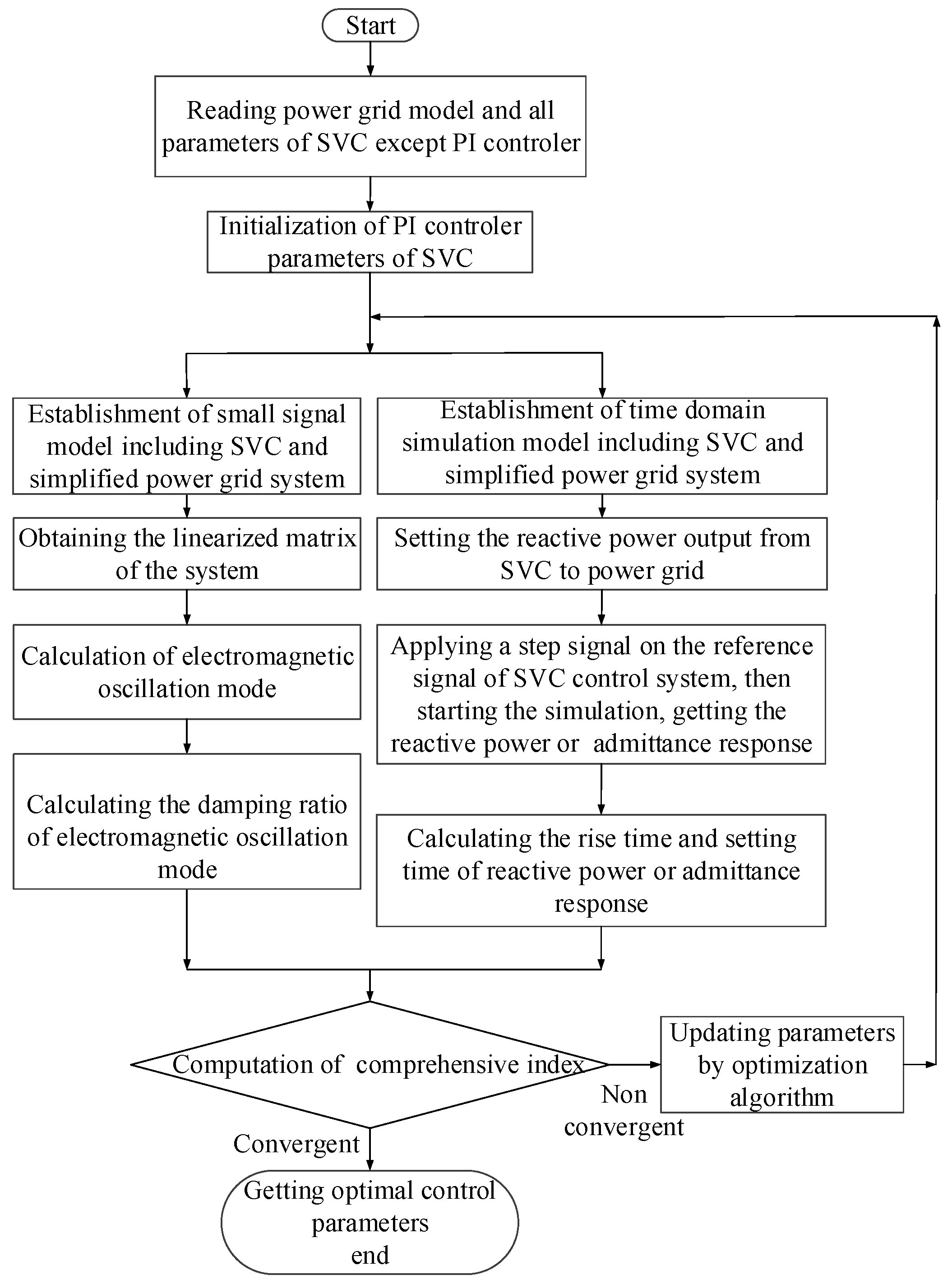
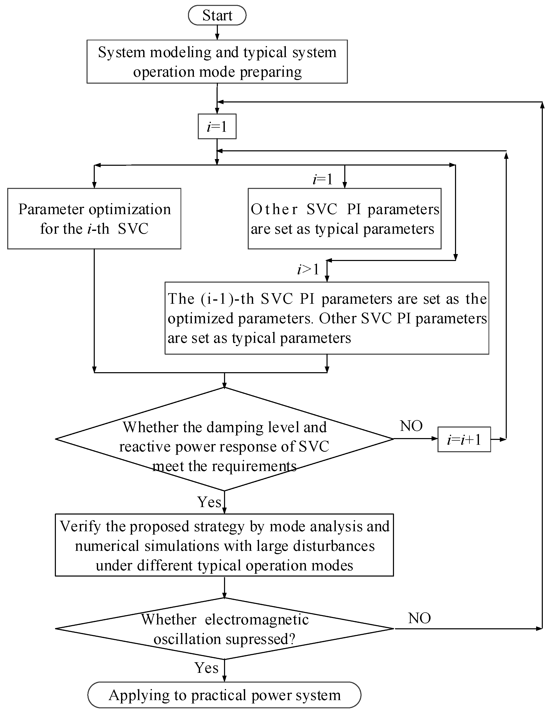
Optimization Process

The optimization procedure of SVC PI parameters is shown in Figure 11.
The goal of optimization is to find the appropriate PI parameters K * to minimize the integrated objective function, namely, in order to ensure that there is no unstable electromagnetic oscillation, while the reactive power response time is kept small.
K * = arg min J ( K )
It is important that the evaluation of electromagnetic oscillation suppression capability should consider the faults such as power supply tripping, which may decrease the short-circuit capacity of the system, and line tripping, which may increase the electrical distance.
According to the result in Section 3, the greater the capacity of SVC, the higher the risk of electromagnetic oscillation. Therefore, in the risk assessment of electromagnetic oscillation, SVCs should be considered to maintain full operation when there are multiple SVCs. In the case of multiple SVCs, it is difficult to optimize all SVC control parameters simultaneously. As shown in Figure 12, a compromise solution can be achieved.

5. Case Study

Because the parameters optimization is based on a simplified model, it is necessary to establish a detailed electromagnetic transient model to verify its adaptability.
A simplified transmission system with SVCs is shown in Figure 4. The capacity of an SVC is ±60 Mvar, the length of the AC line is 1000 km. At SVC control parameters Kp = 2, Ki = 100, the system remains stable without any disturbance. When the equivalent impedance of the system increases from 60 to 80 Ω, an unstable electromagnetic oscillation occurs.
The SVC parameters are adjusted by the above optimization method. The PI parameter range is set to be: Kp ∈ [0.1,3], Ki ∈ (10,300]. The upper limit of oscillation frequency fmax is 250 Hz. The weight coefficient of each oscillation mode pi = 1. The weight coefficient of rise time T0.9 and settling time Ts is 1. The weight coefficient of reactive power regulation performance index m1 is 1, the weight coefficient of electromagnetic oscillation suppression capability index is 2. T0.9 ∈ [0.01,0.5], Ts ∈ [0.02,1]. After optimization, Kp = 1.0751, and Ki = 162.8425.
The step response simulation contrast before and after SVC parameter optimization is shown in Figure 13. The optimization improves the suppression of electromagnetic oscillation effectively while decreasing the step response performance of SVC slightly.

6. Application in CTAIP

6.1. Parameter Optimization of CTAIP

The results of parameter optimization under the power grid operation mode of dry-season are shown in the Table 2. After optimization, kp decreased and ki increased.
The step response comparison of SVCs under the power grid operation mode of dry-season are shown in Table 3. The reactive power regulation performance of SVC was reduced after optimization. T0.9 decreased less than 0.07 s, Ts decreased less than 0.13 s.

6.2. Validation of Control Strategy

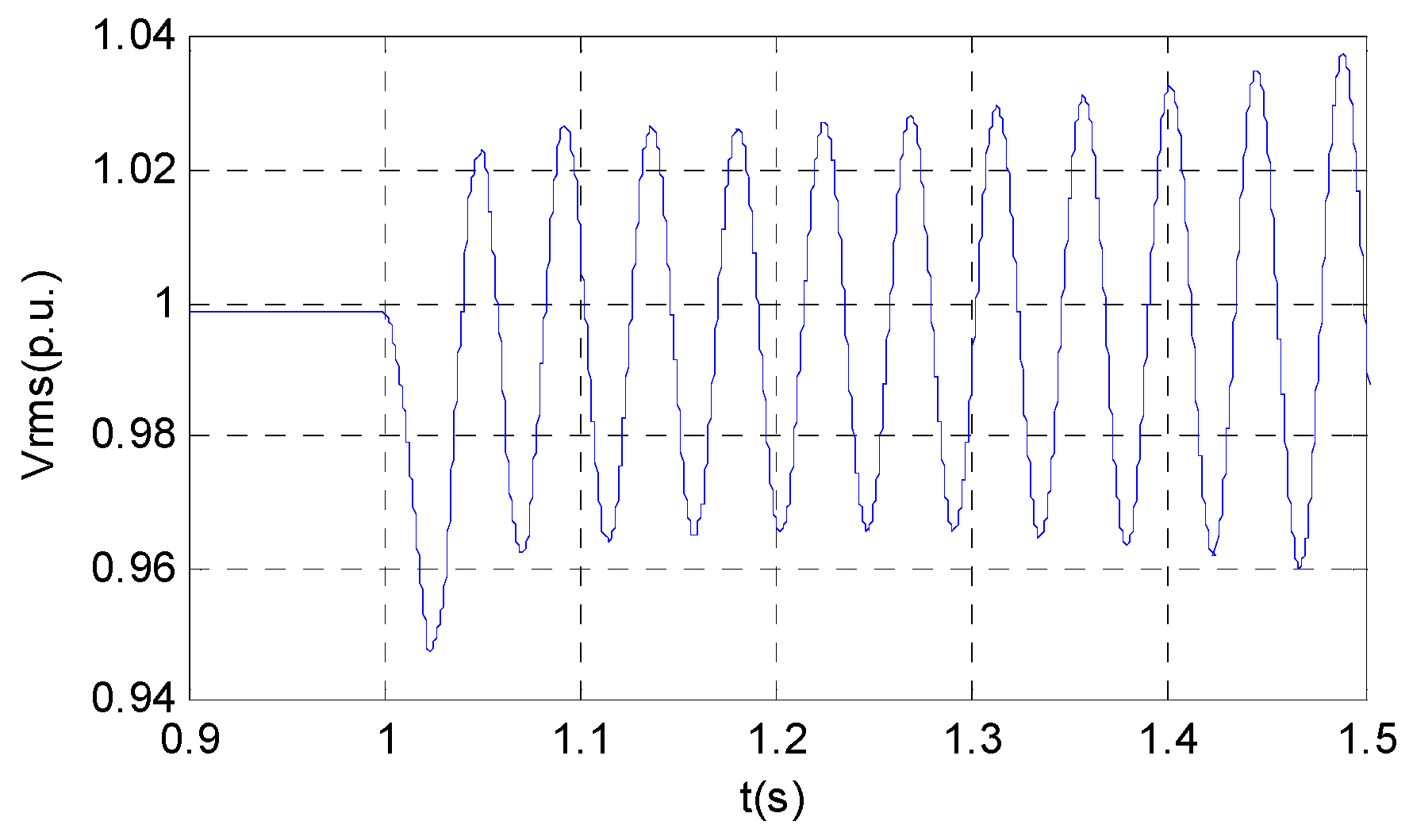
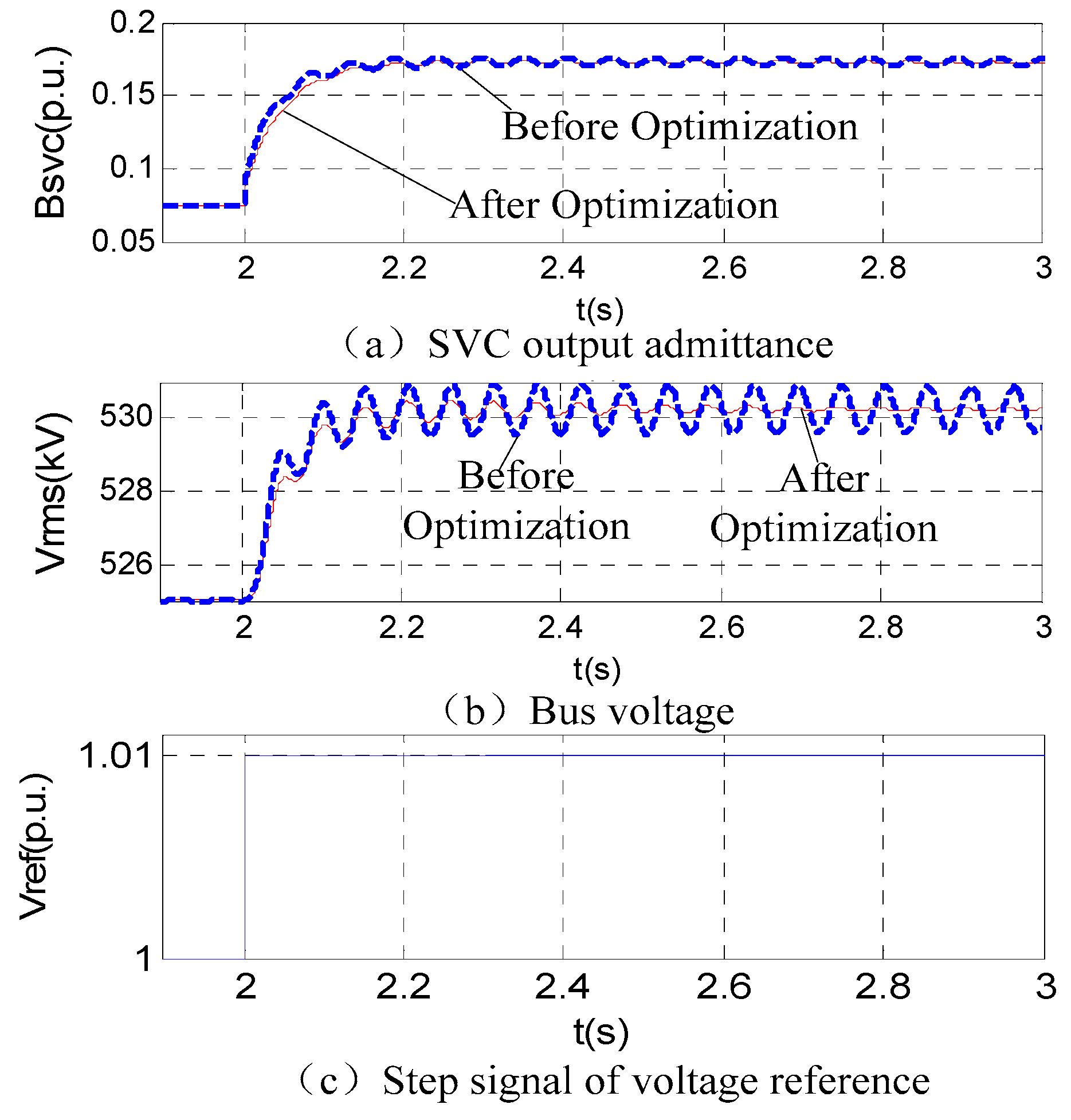
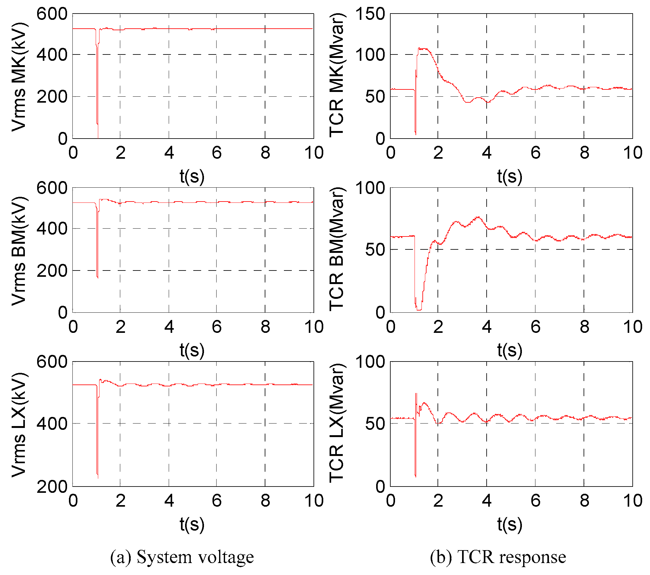
6.2.1. Simulation with PSCAD/EMTDC

In order to verify the effectiveness of the proposed strategy, the simulation models of the CTAIP and related power grids were established in PSCAD/EMTDC, and the large disturbance simulation was carried out.
The comparison of system dynamic responses under faults is shown in Figure 14. Electromagnetic oscillations with frequency of 22.7 Hz and 19.2 Hz were excited in the system under the N-2 fault of the line XM-LX and line BT-MK before the optimization of SVC PI parameters. The oscillations decayed rapidly after the optimization under faults.

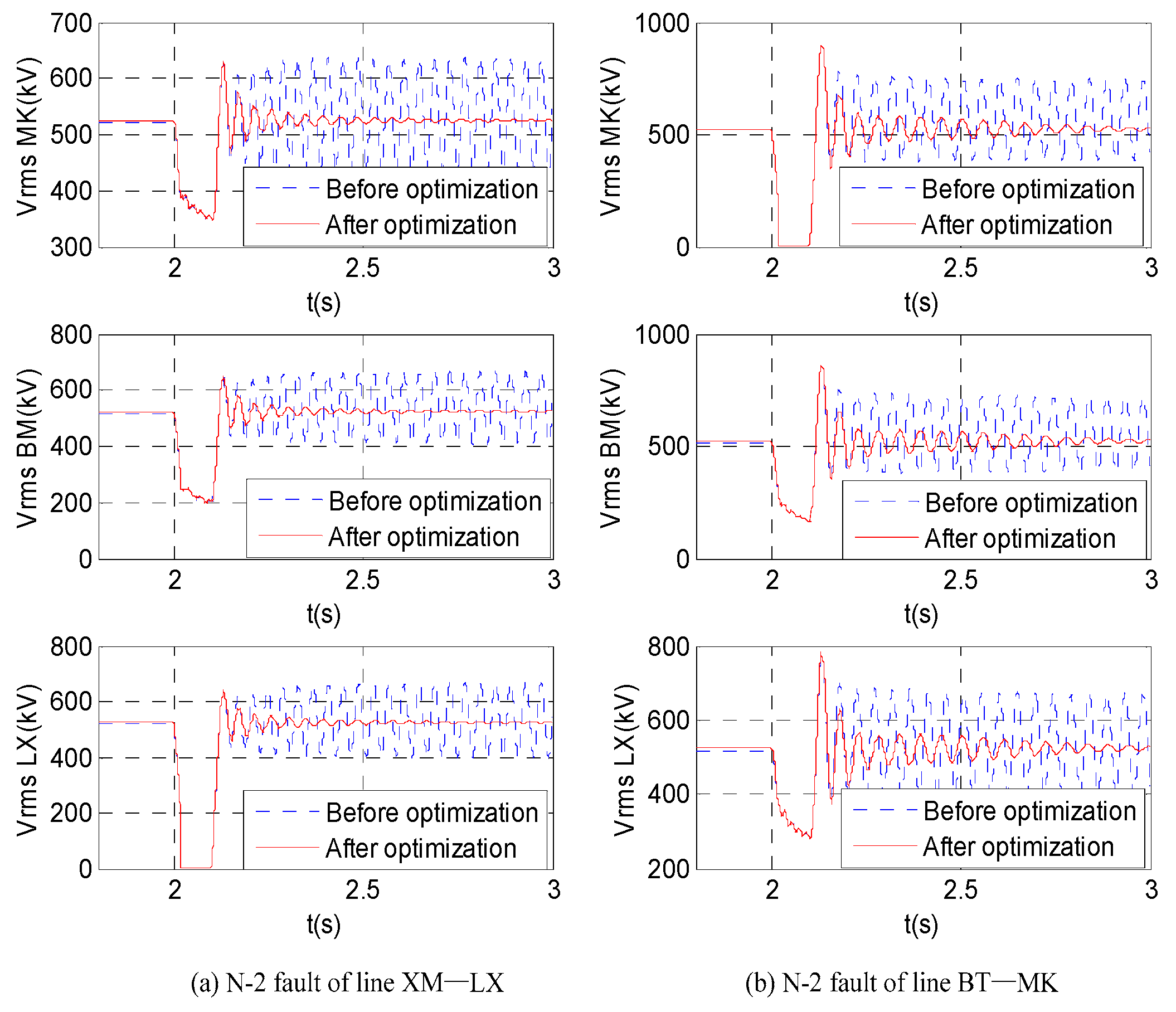
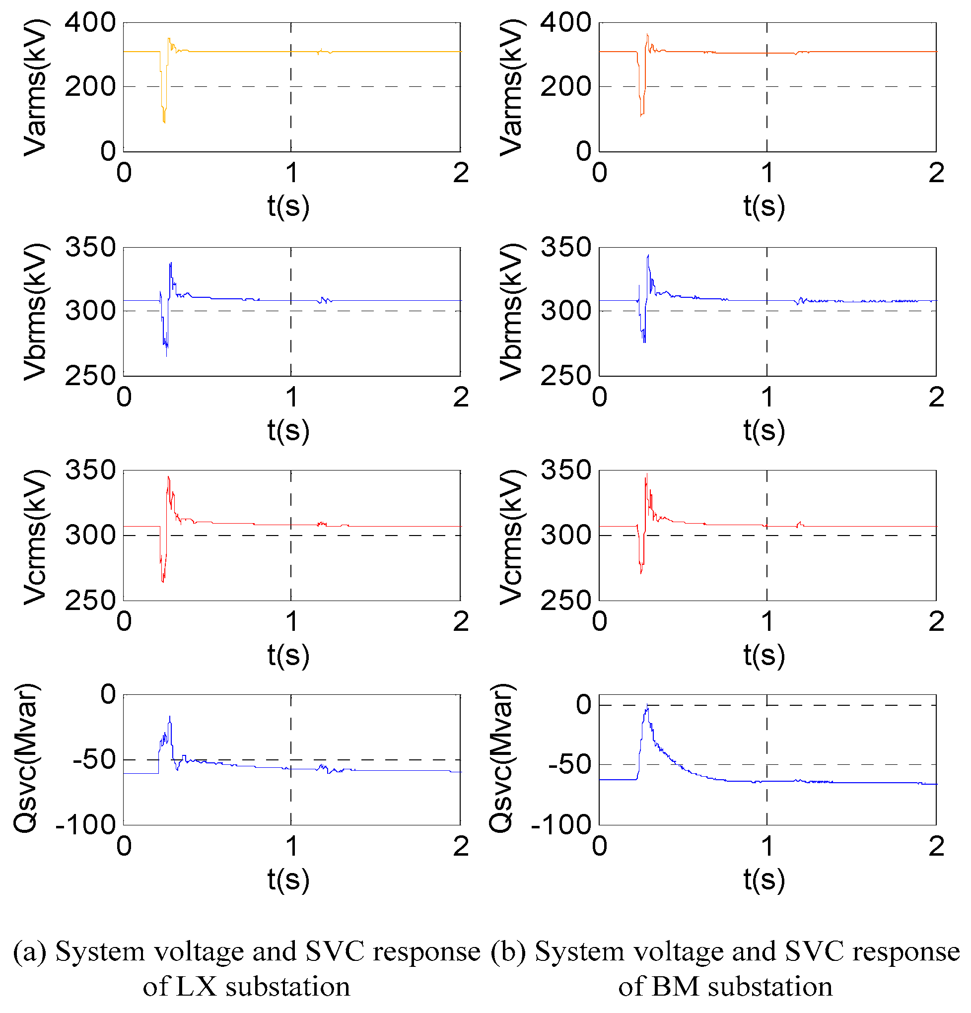
6.2.2. Simulation with RTDS

A RTDS hardware-in-the-loop platform was built to verify the effectiveness of the proposed strategy and adaptability of the optimized parameters, as shown in Figure 15. In this platform, the CTAIP and related power grids were established and six sets of SVC control and protection systems were connected.
The simulation results on the RTDS simulation platform basically agreed with the PSCAD. The system dynamic response under N-2 fault of the line BT-MK after SVC parameters optimization with RTDS is shown in Figure 16. With the optimized SVC parameters, the electromagnetic oscillation was suppressed, and the reactive power response of the TCRs was desirable.

6.3. Engineering Verification

In order to investigate the response characteristic of SVCs, a short-circuit grounding test was carried out on line LX-LZ. The basic principle of the test is shown in Figure 17. The dynamic response of the system and SVCs under the test is shown in Figure 18.
Figure 18 shows that after the ground fault of phase A occurs, the voltage drops to about 100 kV, and the voltage of phase B and C drops to 260 kV. Reactive power absorbed by SVC is reduced from 60 Mvar to 0 in about 60 ms. After the failure disappears, the output of SVC gradually restores to its initial state.
The test results showed that all the SVC operation logic is correct, SVCs do not cause unstable electromagnetic oscillation, and the reactive power response speed of SVC is high. The effectiveness and practicability of the strategy proposed in this paper is verified.

7. Conclusions

In this paper, the mechanism of electromagnetic oscillation in the weak networking power system caused by SVCs is discussed by eigenvalue analysis and the influence factors of electromagnetic oscillation. Research results show that, with the increase of transmission line length, the frequency of electromagnetic oscillation decreases. The oscillation frequency may be less than 50 Hz when the line length is longer than 500 km. With the increase of the equivalent impedance of the system, the electromagnetic mode damping decreases. Access of SVCs deteriorate the electromagnetic mode damping. The larger the capacity of SVC grows, the smaller the damping becomes. With the increase of the PI parameters of SVC, the electromagnetic mode damping decreases. Reducing PI parameters directly can suppress the oscillation, but it will seriously weaken the voltage regulation performance of the SVC. Therefore, the PI parameter optimization method considering voltage regulation performance and electromagnetic oscillation suppression was proposed. The method uses the voltage response rising time and the setting time of SVCs as performance indicators of voltage regulation, taking the damping level of electromagnetic oscillation mode as the performance index of SVC electromagnetic oscillation suppression ability. Combining the two indicators to form a comprehensive optimization index function, an intelligent optimization algorithm is applied to solve the problem. Finally, the optimization strategy was applied to the CTAIP. The results from numerical simulations validated the effectiveness and practicability of the proposed method. Field test results further proved the effectiveness of the strategy. The main contribution of the proposed strategy is to provide a practical and systematic method to prevent electromagnetic oscillation caused by SVCs and to give consideration to the reactive power regulation performance of weak power grid systems.

Author Contributions

Conceptualization, H.S. and X.S.; Methodology, H.S. and X.S.; Software, H.S. and X.S.; Validation, H.S. and Y.T.; Formal Analysis, H.S., H.Z., and X.S.; Investigation, H.Z. and L.D.; Data Curation, H.S. and Y.T.; Writing-Original Draft Preparation, H.S., X.S. and G.C.; Writing-Review & Editing, H.S., X.S., L.X., G.C. and C.F.; Visualization, H.S., X.S., and Y.T.; Supervision, H.Z., Y.X.; Funding Acquisition, L.D.

Funding

This study is supported by the state grid corporation science and technology Project (The coordinated control method and application of wide-area hybrid power generation to improve the clean energy consumption ability and acceptability in weakly connected power grid, 5100-201936010A-0-0-00).

Conflicts of Interest

The authors declare no conflict of interest.

References

  1. Peng, Q.; Yang, H.Y.; Wang, H.; Blaabjerg, F. On Power Electronized Power Systems: Challenges and Solutions. In Proceedings of the IEEE Industry Applications Society Annual Meeting (IAS), Portland, OR, USA, 23–27 September 2018. [Google Scholar]
  2. Hu, B.J.; Yuan, H.; Yuan, M.X. Modeling of DFIG-Based WTs for Small-Signal Stability Analysis in DVC Timescale in Power Electronized Power Systems. IEEE Trans. Energy Convers. 2017, 32, 1151–1165. [Google Scholar] [CrossRef]
  3. Wang, L.; Xie, X.R.; Jiang, Q.R.; Liu, X.D. Centralised solution for subsynchronous control interaction of doubly fed induction generators using voltage-sourced converter. IET Gener. Trans. Distrib. 2015, 9, 2751–2759. [Google Scholar] [CrossRef]
  4. Chowdhury, M.; Mahmud, M.; Shen, W.; Pota, H. Nonlinear controller design for series-compensated DFIG-based wind farms to mitigate subsynchronous control interaction. IEEE Trans. Energy Convers. 2017, 32, 707–719. [Google Scholar] [CrossRef]
  5. Watson, W.; Coultes, M.E. Static exciter stabilizing signals on large generators-mechanical problems. IEEE Trans. Power Appar. 1973, 92, 204–211. [Google Scholar] [CrossRef]
  6. Bahrman, M.; Larsen, E.V.; Piwko, R.J.; Patel, H.S. Experience with HVDC- turbine-generator torsional interaction at Square Butte. IEEE Trans. Power Appar. 1980, 99, 966–975. [Google Scholar] [CrossRef]
  7. Prabhu, N.; Padiyar, K.R. Investigation of subsynchronous resonance with VSC-based HVDC transmission system. IEEE Trans. Power Deliv. 2009, 24, 433–440. [Google Scholar] [CrossRef]
  8. Harnefors, L. Analysis of subsynchronous torsional interaction with power electronic converters. IEEE Trans. Power Syst. 2007, 22, 305–313. [Google Scholar] [CrossRef]
  9. Emadi, A.; Khaligh, A.; Rivetta, C.H.; Williamson, G.A. Constant power loads and negative impedance instability in automotive systems: Definition modeling stability and control of power electronic converters and motor drives. IEEE Trans. Veh. Technol. 2006, 55, 1112–1125. [Google Scholar] [CrossRef]
  10. Bi, T.S.; Li, J.Y.; Zhang, P.; Mitchell-Colgan, E. Study on response characteristics of grid side converter controller of PMSG to sub-synchronous frequency component. IET Renew. Power Gener. 2017, 11, 966–972. [Google Scholar] [CrossRef]
  11. Huang, P.H.; EI Moursi, M.; Xiao, S.W.; Kirtley, J.L. Subsynchronous resonance mitigation for series-compensated DFIG-based wind farm by using two-degree-of-freedom control strategy. IEEE Trans. Power Syst. 2015, 30, 1442–1454. [Google Scholar] [CrossRef]
  12. Chen, Y.H.; Huang, B.Y.; Sun, H.S.; Wang, L. Analysis of control interaction between D-PMSGs-based wind farm and SVC. J. Eng. 2019, 16, 1266–1270. [Google Scholar] [CrossRef]
  13. Tao, H.; Chong, L.; Ban, L.G.; Zhu, Y.Y.; Wei, C.X.; Li, L.F.; Jiang, W.P.; Dong, P.; Zhao, B.; Liu, W.L. Real-time simulation and parameter optimization of SVC control strategy for central-Tibet power grid. Power Syst. Technol. 2014, 38, 1001–1007. [Google Scholar]
  14. Chen, G.; Tang, F.; Shi, H.B.; Yu, R.; Wang, G.H.; Ding, L.J.; Liu, B.S.; Lu, X.N. Optimization strategy of hydro-governors for eliminating ultra low frequency oscillations in hydro-dominant power systems. IEEE J. Emerg. Sel. Top. Power Electron. 2018, 6, 1086–1094. [Google Scholar] [CrossRef]
  15. Bian, X.Y.; Geng, Y.; Lo, K.L.; Fu, Y.; Zhou, Q.B. Coordination of PSSs and SVC damping controller to improve probabilistic small-signal stability of power system with wind farm integration. IEEE Trans. Power Syst. 2016, 31, 2371–2382. [Google Scholar] [CrossRef]
  16. Abdulrahman, I.; Radman, G. Wide-area-based adaptive neuro-fuzzy SVC cntroller for damping interarea oscillations. Can. J. Electr. Comput. Eng. 2018, 41, 133–144. [Google Scholar]
  17. Asghari, R.; Mozafari, B.; Naderi, M.S.; Amraee, T.; Nurmanova, V.; Bagheri, M. A novel method to design delay-sheduled controllers for damping inter-area oscillations. IEEE Access 2018, 6, 71932–71946. [Google Scholar] [CrossRef]
  18. Alimuddin; Nurhalim, G.; Arafiyah, R. Optimization placement static var compensator (SVC) using artificial bee colony (ABC) method on PT PLN (Persero) Jawa-Bali, Indonesia. In Proceedings of the 2018 1st International Conference on Computer Applications & Information Security (ICCAIS), Riyadh, Saudi Arabia, 4–6 April 2018. [Google Scholar]
  19. Pandya, M.C.; Jamnani, J.G. Coordinated control of SVC and TCSC for voltage profile improvement employing particle swarm optimization. In Proceedings of the 2017 International Conference on Smart Technologies for Smart Nation (SmartTechCon) 2017 International Conference on Smart Technologies for Smart Nation (SmartTechCon), Bangalore, India, 17–19 August 2017. [Google Scholar]
  20. Zhang, K.S.; Shi, Z.D.; Huang, Y.H.; Qiu, C.J.; Yang, S. SVC damping controller design based on novel modified fruit fly optimization algorithm. IET Renew. Power Gener. 2018, 12, 90–97. [Google Scholar] [CrossRef]
Figure 1. Structure diagram of central Tibet AC interconnection project (CTAIP).
Energies 12 03489 g001
Figure 2. Effect of switching single reactor on system voltage.
Energies 12 03489 g002
Figure 3. Electromagnetic oscillation induced by static VAR compensators (SVCs).
Energies 12 03489 g003
Figure 4. Simplified transmission system with SVC.
Energies 12 03489 g004
Figure 5. Primary circuit of a TCR+FC type SVC.
Energies 12 03489 g005
Figure 6. Simplified control block diagram of SVC.
Energies 12 03489 g006
Figure 7. Variation trend of eigenvalues of the main electromagnetic oscillation mode with transmission line length and equivalent impedance of power supply (with no SVC).
Energies 12 03489 g007
Figure 8. Variation trend of eigenvalues of the main electromagnetic oscillation mode with capacities of SVCs (1000 km transmission line).
Energies 12 03489 g008
Figure 9. Variation trend of eigenvalues of the electromagnetic oscillation mode with SVC PI parameters (1000 km transmission line).
Energies 12 03489 g009
Figure 10. Eigenvalue of the electromagnetic oscillation mode and admittance step response of the SVC under different PI parameters.
Energies 12 03489 g010
Figure 11. Optimization procedure of SVC PI parameters.
Energies 12 03489 g011
Figure 12. Multi-SVC parameter optimization process.
Energies 12 03489 g012
Figure 13. Simulation comparison of SVC parameters before and after optimization.
Energies 12 03489 g013
Figure 14. Dynamic response of the system under faults before and after SVC parameter optimization with PSCAD.
Energies 12 03489 g014
Figure 15. RTDS hardware-in-the-loop platform for verifying the proposed strategy.
Energies 12 03489 g015
Figure 16. Dynamic response of the system under N-2 fault of the line BT-MK after SVC parameter optimization with RTDS.
Energies 12 03489 g016
Figure 17. Basic principle of artificial short circuit grounding test.
Energies 12 03489 g017
Figure 18. Dynamic response of the system and SVC under an artificial short-circuit grounding test.
Energies 12 03489 g018
Table 1. Primary device parameters.
Xs (Ω)R (Ω/km)X (Ω/km)B (Siem/km)Transformer (750 MVA)
600.01660.29684.24 × 10−6X12 (%)X13 (%)X23 (%)
124430
Table 2. The optimized SVC control parameters.
Parameter SourceLXBMMK
kpKikpKikpKi
Before optimization410041004100
After optimization1.123794.86211.9826152.28152.0596197.2081
Table 3. The comparison of step response before and after optimization.
Parameter SourceLXBMMK
T0.9 (s)Ts (s)T0.9 (s)Ts (s)T0.9 (s)Ts (s)
Before optimization0.200.490.160.430.140.41
Parameters optimization0.270.620.190.540.160.49

