Abstract
Hydrocarbon is a major source of energy for sustainable development. Storage of hydrocarbon products, however, requires a significant amount of land space to land-scarce countries like Singapore. This paper presents an alternative way of storing hydrocarbon in Singapore coastal waters through the innovative design of a floating hydrocarbon storage facility. The design comprises free-floating and self-stabilizing tanks enclosed by barges that form a floating hydrocarbon storage facility. The tanks are made of prestressed concrete and they are designed to be self-stabilized when floating in the sea water. Owing to the lack of available design guidelines, design requirements on the stability and motion criteria for floating storage tanks are developed based on a review of existing codes of practice and design specifications for both onshore tanks and offshore vessels. A comprehensive study on the hydrostatic performance of various proposed floating tank design concepts with different storage capacities is carried out. This paper aims to give design recommendations on the tank’s storage capacity and dimensional aspect ratios that fulfill the recommended stability requirements and motion criteria.
1. Introduction
Singapore relies heavily on the import of fuels to ensure a secure, reliable, and diversified supply of competitively-priced energy. Among various energies sources, petroleum products and crude oil occupied 94% of the total imported energy in 2015. Thus, a vast amount of space is required to store and trade hydrocarbon products. In land-scarce countries like Singapore, there is a need to create additional space through innovative engineering solutions. For example, Singapore created an artificial island, called Jurong Island, in 2009 by amalgaming seven offshore islands through land reclamation to grow the petrochemical industry. Subsequently in 2014, the Jurong Rock Caverns, excavated at some 120 m beneath the ground and was put into operational use for massive oil storage. These approaches of creating space have their own limitations.
Storing oil in the sea may be an appealing alternative solution, particularly for coastal countries. This idea appeals to the oil & gas industry for decades. In 1969, a submerged fuel storage facility named Khazzan No. 1 was built in Dubai (see Figure 1). This bottomless inverted funnel-shaped storage tank was designed to store crude oil based on the water displacement principle [1]. The same principle was later adopted by Mo [2] in the design of the gravity-based Condeep oil storage platforms (see Figure 2).
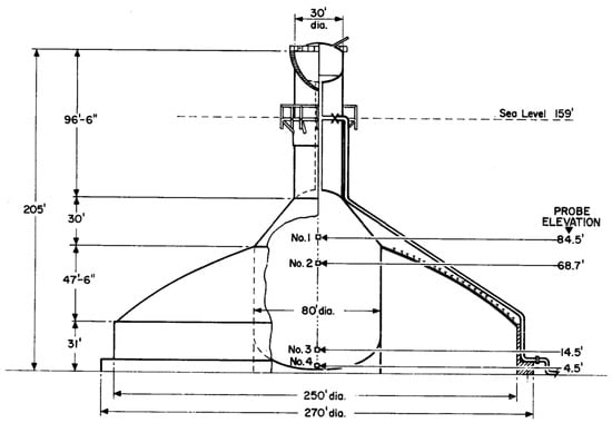
Figure 1.
Sectional view of Khazzan No. 1 [1].
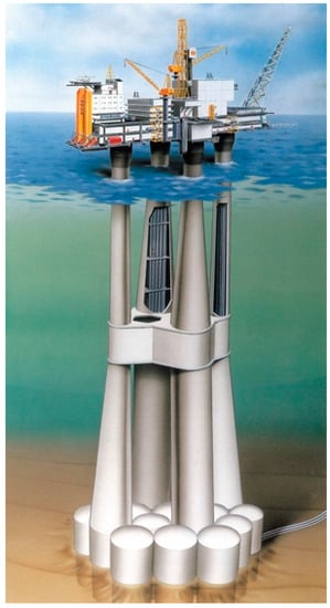
Figure 2.
An example of Condeep oil storage platform: Troll A [3].
Although gravity-based offshore oil storage facilities stand steadily under harsh environmental conditions, their applications are largely limited by the seabed condition. To promote the storage of fuel in relatively calm waters, Hirata [4] proposed the concept of floating bottomless tanks entitled “Floating Oil Storage Installation” (see Figure 3). The floatability is also achieved by water displacement principle, and the roof can be used to provide buoyancy when oil level is low. A key concern for adopting the water displacement principle, however, is the contamination of both the petrochemical product and the marine environment, and is certainly not suitable for the storage of clean petrochemical products (CPP).
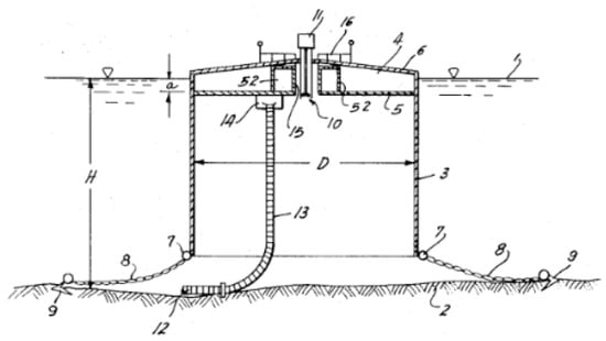
Figure 3.
Floating Oil Storage Installation involving floating tank moored to fixed anchors [4].
VLFS (very large floating structures) technology has also been adopted in the oil & gas industry. In Japan, there are two floating fuel storage facilities: Kamigoto Oil Storage Base and the Shirashima Oil Storage Base (see Figure 4). Both storage facilities comprise several very large box-shaped steel storage modules that are compartmentalized into a number of oil tanks [5]. There is also a similar large prestressed concrete floating production unit (FPU) for crude oil storage stationed on N’Kossa field, Congo (see Figure 5) [6].
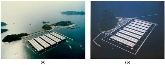
Figure 4.
Floating oil storage facilities: (a) Kamigoto Oil Storage Base and (b) Shirashima Oil Storage Base [7].
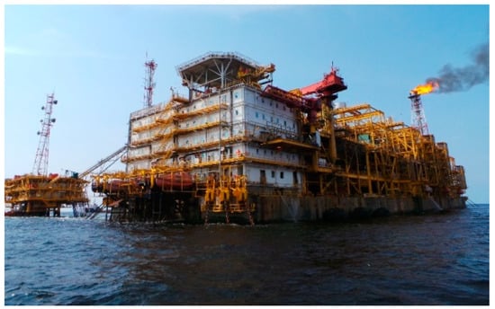
Figure 5.
N’Kossa floating prestressed concrete barge [8].
The aforementioned existing VLFS storage facilities provided solid solution to long-term and/or emergency oil stockpiling in the sea. These facilities, however, are designed to be a subsidiary system to the onshore oil farms and they also lack the capability for frequent processing and trading operations of the petrochemical products. Therefore, a stand-alone floating storage facility that has the full functionality as a land-based oil terminal is highly desirable. To this end, the authors have proposed an innovative design entitled “Floating Hydrocarbon Storage and Bunker Facility” which has been granted a provisional patent [9]. Figure 6 shows the plan and side views of the FHSBF. Figure 7 shows a 3D architectural rendering view. This concept is self-contained with all essential facilities such as power generation plant, desalination plant, slop and wastewater treatment plant, control room, warehouse, pump rooms, offices and accommodation quarters for workers on the floating offshore base. It also has floating berths on the sides for oil tankers to load/offload hydrocarbon products. The floating berths and barges also serve as a protection of the fuel storage modules against waves and ship berthing forces. Note that the dimensions are indicative only and they are subject to changes depending on the local design requirements, tank size, environmental conditions, etc.
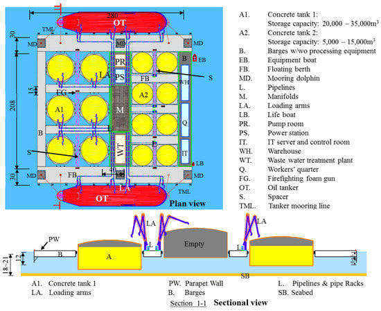
Figure 6.
Plan and sectional views of FHSBF.
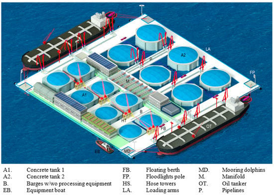
Figure 7.
3D architectural rendering view of FHSBF.
Enclosed within the floating berths and barges are free-floating self-stabilizing hydrocarbon storage tanks. These tanks can be easily constructed in a standard dockyard. During operation, the tanks are loaded/unloaded independently without affecting each other. The cross-section of the tanks is cylindrical that enjoys the benefit of optimal resistance to hydrostatic pressure (see Figure 8). The tanks are made of prestressed concrete and they are designed to be self-stabilized when floating in the water. As the tanks are freely floating, its lateral position is held in place through contact between the floater walls, which are relatively stronger than the tank hull, with the rubber fenders installed along the surrounding barges. The space within the floaters can be used for piping routing, personnel access and water ballasting when necessary.
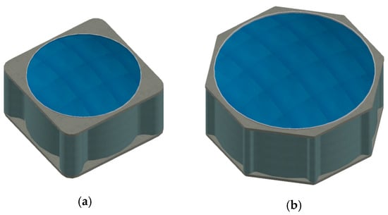
Figure 8.
Isometric view of hydrocarbon storage tank: (a) small tank and (b) big tank.
As the floating tanks are surrounded by floating barges serving as breakwaters [10], the wave-induced motions of the tanks are expected to be small [11]. However, other environment loads such as water current and wind, may be significant and may lead to undesirable levels of motion of the tanks that could lead to instability. This paper is concerned with the stability and motion of the proposed self-stabilizing tanks under environmental loads. The tanks must satisfy the following design and functional requirements:
- The tank shall be self-stabilizing with or without internal free surface effect;
- The tank shall have a flexible range of storage capacity to cater for operators’ commercial needs;
- Motions of the tanks shall be controlled within an acceptable range so that it would not pose a problem during operation under working condition and survivability is not compromised under extreme environmental condition;
- The tank sizes shall be designed with the desire to use minimum sea space;
- The clearance between the seabed and tank bottom must be greater than a minimum specified value so as not to hinder the flow of water.
The focus of this paper is placed on establishing recommended stability and motion criteria of floating storage tanks as well as evaluating the hydrostatic performance of various proposed tank designs. Owing to Singapore’s benign sea conditions, it is justifiable to evaluate the tank’s performance based on a hydrostatic analysis. Nevertheless, comprehensive studies on hydrodynamic and structural performances of the proposed storage tanks as well as hydroelastic response of the surrounding barges were also carried out and interested readers may refer to results reported in references [12,13,14,15,16] for more details.
2. Review of Existing Codes of Practice and Design Specifications
As mentioned earlier, the stability and motion of the self-stabilizing floating tanks under environmental loads are critical. The magnitudes of tank motion must be constrained within appropriate limits so that the loading/offloading process is not disrupted during operation under working weather condition. Under extreme weather conditions, the tank motion must not be excessive as to cause damage to surrounding structures and facilities. Obviously, the stability of the floating tank must be ensured throughout its service life. As there is a lack of available design codes and specifications for floating storage tanks, recommendations on intact stability and motion criteria of floating tanks will first be established based on existing design standards for both onshore tanks and offshore vessels.
2.1. Existing Design Standards for Land-Based Storage Tanks
Onshore storage tanks are bottom founded and thus they are generally free of lateral movements. However, uneven settlement at the bottom may lead to rigid body tilting of a tank, which is often addressed as the planar tilt. According to API standard 653, excessive planar tilt will induce a number of undesirable consequences as listed below [17]:
- Malfunction of floating roof seals;
- Binding of a floating roof;
- Problems with connecting pipes;
- Problems with surface water drainage from the tank pad;
- Tank shell buckling;
- Overstress of shell or bottom plates.
While API 653 does not specify any explicit limit on the planar tilt of storage tanks, EEMUA 159 emphasizes that the out-of-verticality at top of the tank shell shall not exceed 1% of the tank height (see Figure 9) [18]. In terms of angular tilt, this is about 0.6°. Similar to the clauses listed in API 653, this stringent limit is imposed to onshore storage tanks in order to avoid malfunctioning of floating roof, damage to the tank structure as well as pipeline connections.
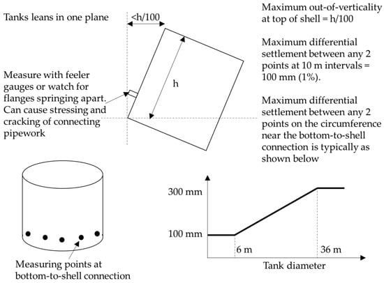
Figure 9.
Planar tilt of storage tanks. Adapted from [18].
It is worth mentioning that there will be no floating roof in the proposed floating tanks in view of the structural difficulty to effectively resist liquid movements under tank angular motions. As it can be seen from Figure 6, loading arms and/or flexible hoses are utilized in the floating storage base for loading/offloading operations, which allow a certain degree of differential movements between the tanks and pipelines. Furthermore, as the proposed floating tanks are made of prestressed concrete instead of conventional thin-walled steel plates that are often used for land-based tanks, shell buckling is not a concern. For these reasons, the limit on tank’s tilt as specified by EEMUA 159 may not be applicable to the proposed free floating self-stabilizing storage tanks.
2.2. Existing Design Standards for Offshore Vessels
The degrees of ship motions have a pivotal impact on their survivability under environmental loads, and are normally associated with the stability of vessels. There are well-established classification societies issuing codes of practice for vessels’ stability. For example, DNV rules for classification of ships list the following criteria for intact stability for all ships [19]:
- The area under the righting lever curve (GZ curve) is not to be less than 0.055 m-radians up to θ = 30° angle of heel and not less than 0.09 m-radians up to θ = 40° or the angle of flooding θf if this angle is less than 40°. Additionally, the area under the righting lever curve between the angles of heel of 30° and 40° or between 30° and θf, if this angle is less than 40°, is not to be less than 0.03 m-radians;
- The righting lever (GZ) is to be at least 0.20 m at an angle of heel equal to or greater than 30°;
- The maximum righting lever should occur at an angle of heel preferably exceeding 30° but not less than 25°;
- The initial metacentric height, GM0 is not to be less than 0.15 m.
It should be noted that ships are designed to cruise in the open sea. Thus, the capability of restoring to its original upright position when the ship undergoes a large tilt under a severe environmental condition is crucial. Furthermore, large heel angles may not induce detrimental consequences to the structure when it is far away from other ships or structures.
The proposed floating tanks, however, are enclosed by barges/platforms with rubber fenders (see Figure 6). Large tilting angles could disrupt working process or even damage the tank and the surrounding barges. For this reason, the first three requirements on ship’s stability by DNV may not be applicable to floating tanks that are kept in position by floating barges via rubber fenders. However, the requirement on minimum initial metacentric height not smaller than 0.15 m shall be retained. Additionally, the tilting angle shall not exceed 5° under extreme weather conditions to ensure no damage to the tank itself and the surrounding structures as well.
In addition to stability and motion of ships, the International Convention of the Prevention of Pollution from Ships (MARPOL) made it mandatory that new oil tanks must have double hulls [20]. This is to prevent oil pollution from operational measures and accidental discharges. The proposed floating hydrocarbon storage facility, however, is designed to be a permanently moored floating structure instead of a marine vessel. Therefore, the design does not necessarily comply with MARPOL regulations. Nevertheless, the relevant prevention of pollution shall be taken into account as the facility is to be used for hydrocarbon storage. It should be noted that all the storage tanks are protected by external barge structures from environmental loads and direct contact with ships. As such, the design of the entire floating hydrocarbon storage facility may be regarded as a “double hull” concept. In addition, the storage tanks have appropriate separation distance from each other with the aid of structural spacers and floating barges [21]. The enclosing barges are also designed to be able to contain leaked oil from a fully loaded tank. Furthermore, prestressed concrete structures have much thicker walls than double hull oil tankers. A separate study by the research team showed that the proposed design has a better resistance to ship impact than conventional oil tankers [22]. As a result, it is justifiable to consider either single hull or double hull for the design of the floating tanks.
2.3. Existing Recommendation on Motion Criteria of Vessels during Berthing
In order to satisfy operational requirements, the motion of floating tanks under normal working environmental conditions shall be limited to ensure smooth and efficient loading/offloading operations. According to PIANC Working Group 24, the acceptable movements of both oil tankers and gas tankers are determined by the allowable reach of loading arms [23]. Table 1 summarizes the recommended motion criteria for various types of vessels during berthing. For example, the horizontal translations of oil tankers and gas tankers shall not exceed 3 m and 2 m, respectively to ensure a safe loading operation. There are no limits imposed on the allowable yaw, pitch and roll degrees of freedom of an oil tanker as the angular motions are generally well within the design motion envelopes of the loading arms [23]. However, as the proposed storage tanks are significantly smaller than huge oil tankers, they are thus more vulnerable to the environmental conditions. Their angular motions must therefore be controlled within acceptable limits. It is proposed that the 2° limit on rotational motions for a lesser massive gas tanker (see Table 1) be adopted for the floating tanks.

Table 1.
Recommended motion criteria for safe working conditions [23].
A joint Nordic group conducted a similar research on the acceptable movements of moored ships in a harbor under working conditions. The results are somewhat agreeable with those published by PIANC 24. Furthermore, the Nordic group has suggested that the occurrence frequency of critical ship movements should be less than 1 week in a year for most of the cargo ships [24]. In view of this, it is reasonable to apply the 1-year characteristic environmental values to evaluate the motion of floating tanks under working conditions.
2.4. Recommended Stability and Motion Design Criteria for Floating Tank
Based on the review of existing codes of practice and design specifications on both onshore storage tanks and offshore cruising/berthing vessels, together with the consideration of design requirements of the proposed floating tanks, the following design guidelines on tanks’ stability and motion criteria are proposed:
- The initial metacentric height GM0 of moored tanks shall not be smaller than 0.15 m;
- Additional to 1 above, floating tanks that are fully exposed to the open sea need to fulfill all stability requirements as specified by DNV rules for classification of ships [19];
- Sway and surge movements of moored tanks shall not exceed 3 m, and rotational (roll/pitch/yaw) motions of moored tanks shall not exceed 2° under working environmental condition;
- Rotational (roll/pitch/yaw) movements of moored floating tanks shall not exceed 5° under extreme environmental condition.
The acceptable limits on the movement of tanks under extreme condition need to be further reviewed and revised after detailed hydrostatic and structural analyses. The principle is that these critical movements should not cause damage or loss of integrity and stability to the tank itself and surrounding structures and facilities. Furthermore, additional motion criteria for the construction and installation stages need to be fulfilled. However, these will not be addressed herein, as they are not within the scope of this paper.
3. Stability and Motion Analysis of Floating Storage Tanks under Wind and Current Loads
In this section, the hydrostatic response of the floating storage tanks under wind and current will be presented. The stability and motions of the tanks will be investigated against the design criteria established in the previous section. Several types of tanks of various shapes, configurations and aspect ratios are examined with the aim of designing tanks that are self-stabilizing and fulfill the prescribed motion criteria under given environmental conditions.
3.1. Methodology
Consider a floating hydrocarbon storage tank enclosed by floating barges on the sides. As the barges protect the tanks from incoming waves, the tank is mainly subject to wind and water current loads, as illustrated in Figure 10. The shaded region in the figure represents the stored hydrocarbon product. The wind and water current speeds are assumed to be sustained in the model so that a static analysis is possible [24]. Also note, that the fenders are designed to restrain sway and surface motions within prescribed limits. Thus, only angular movements, i.e., roll and pitch, will be studied.
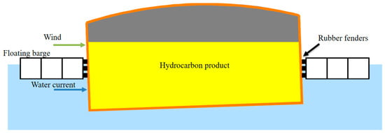
Figure 10.
Floating tank enclosed by barges and subject to environmental loads.
Figure 11a,b show the floating tank in the upright and tilted positions, respectively. Given the information on structural configuration and geometry of tank components as well as fuel loading condition, the locations of the tank’s center of gravity (CG) and center of buoyancy (CB) can be determined as shown in Figure 11. The initial metacentric height, GM0, may be calculated as follows
where KB is the height of the center of buoyancy above the keep, KG the height of the center of gravity above the keel; BM the metacentric radius and can be written as
where Io is the second moment of area of the waterplane, and V the displaced water volume. When the tank is filled with hydrocarbon products, the free surface of the stored liquid leads to a virtual rise in the vertical center of gravity, which reduces the stability of the tank as shown in Figure 11b. The rise in CG due to free surface effect may be expressed as
where ρfuel and ρwater denote the densities of fuel and water, respectively; G’ is the location of the new center of gravity; and Ii the second moment of area of the liquid waterplane. The metacentric height of the tilted tank is given by G’M0. Note that the location of the metacenter M0 remains virtually the same for small tilting angle of the tank (< 5°).
GM0 = KB + BM − KG,
BM = Io/V,
GG’ = (ρfuel/ρwater) Ii/V,

Figure 11.
Floating tank at (a) upright and (b) tilted positions.
Next, we may estimate the effect of wind and water current loads on the tilting angle of the storage tank. According to DNV standards [25,26], the wind and water current pressures are reasonably assumed to be uniformly distributed on the tank wall, as shown in Figure 12. Also shown in Figure 12 are two load combinations, where the wind and current are in the (a) same direction and (b) opposite directions. Without further detailed environmental data on the directions and likelihood of their maxima occurring simultaneously, the two load combinations will be considered herein and the one resulting in the maximum tilting moment will be used to evaluate the maximum tilting angle of the floating tank.

Figure 12.
Tank subject to wind and current forces acting in the (a) same and (b) opposite directions.
Figure 13 shows the forces acting on the floating storage tank. Point A on the figure denotes the intersection between the resultant rubber fender reaction and the metacentric radius (BM). By taking moment about A, the moment equilibrium equation can be written as
where W denotes the weight of the tank; Fw and Fc are the resultant wind load and current load action on the tank; dw and dc refer to the lever arms from wind load center and current load center to the point A, respectively; α the tank tilting angle due to sustained wind and current loads.
W × GM tan α =|Fw dw| + |Fc dc|,
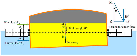
Figure 13.
Forces acting on the floating storage tank.
According to DNV codes of practice, the wind and water current forces exerting on the tank may be written as [25,26]
where vw and vc denote the characteristic wind and water current speeds, respectively; Aw and Ac refer to the projected areas normal to the wind and current actions, respectively; Cs is the shape coefficient and Ch the height coefficient, according to DNV-OS-C301 [25]; and CDS is the steady drag coefficient and may be selected according to DNV-RP-H103 [26].
3.2. Hydrostatic Stability and Motions of Floating Tanks
This section shall examine the hydrostatic stability of the various designs of floating storage tanks with different storage capacities. This section shall also investigate the tilting angle of storage tanks under combined wind and current loads. The proposed hydrocarbon storage and bunkering facility has two sizes of tanks, namely small and big tanks. The small tanks are designed for storing Clean Petrochemical Products (CPP) with a practical storage capacity ranging from 5000 m3 to 15,000 m3. The big tanks are designed for crude and fuel oil storage and their storage capacities range from 17,500 m3 to 35,000 m3. In this study, only small tanks are analyzed as they are inherently less stable than larger and stockier tanks. The big tanks, which can be designed by adopting the same design principles applied to the small tanks, will not be covered herein.
Figure 14 and Figure 15 show the initial design of the tank structure. The tanks are made of light-weight prestressed concrete and they have a double hull structure. Note that L and D denote the length of the outer tank wall and diameter of the inner wall, respectively. Hr, Hw and Hd are, respectively, the heights/depths of the tank roof, wall and bottom deck. H is the total height of the tank. Table 2 summarizes the key geometric information and material properties of the storage tank. In addition, a 1/8 roof height to span ratio (Hr/L) is adopted. The roof is assumed to be stiffened by beams that contribute another 15% to the roof slab weight. Furthermore, a uniformly distributed load of 0.5 kPa due to roof maintenance operation and another equipment weight of 3% of the total tank’s self-weight are assumed to be acting on top of the roof. The equivalent mass of these loads is used to compute the center of gravity (CG) location of the entire tank and mass radius of gyration. The tank bottom is assumed to be a solid concrete slab of constant thickness. When the tank is filled with hydrocarbon product to the designed storage capacity, there will be a minimum 1 m gap between the product top surface and the roof bottom. This gap is necessary to prevent spillover of the product as well as it creates space for inert gas. Unless otherwise noted, all the values listed in Table 2 will be used throughout this paper. Note that the structural properties employed here are based on the results of detailed structural analysis of the floating tanks [15].
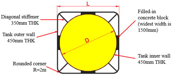
Figure 14.
Initial design of floating storage tank (planar cross-sectional view).
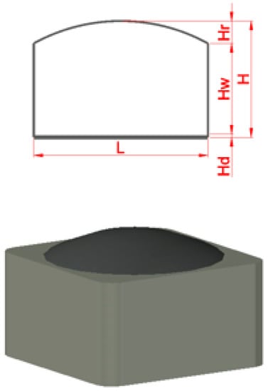
Figure 15.
Side and isometric views of tank with dome roof.

Table 2.
Geometric and material properties for storage tanks.
The environmental conditions for wind and water current at the selected site are assumed as shown in Table 3. As mentioned earlier, the wind and current speeds taking on the characteristic maximum values at their 1-year return period will be adopted for stability analysis under working environmental condition. For analysis under the extreme environmental condition, it is essential to consider the values at their 100-year return period [27,28]. In the following study, Equations (5a) and (5b) are used to calculate the wind and water current forces exerted on the tanks. Equations (1) and (4) are then employed to assess the stability and roll motion of the tanks in question.

Table 3.
Characteristic wind and water current speeds at selected site.
Besides wind and water current, floating tanks are also subjected to wave loads. The dynamic effect of wave loads may lead to sloshing of the stored hydrocarbon product. However, the wave condition in Singapore coastal regions is rather benign due to the shielding from islands and neighboring lands. According to the available hindcast data, the mean significant wave height is generally below 0.25 m [29], although it may exceed 1 m in some exposed areas. Nevertheless, the present hydrocarbon storage facility is proposed to be located in shielded regions and the surrounding floating barges serve as breakwaters that reduce wave loads exerted on the floating tanks. Therefore, waves are expected to have a limited effect on the floating tanks and thus not considered in this study.
Furthermore, the water depth of the coastal regions around Singapore is shallow and a daily tidal variation of 2 m to 3 m is expected [29,30]. In this study, a water depth of 18 m under low tide condition is taken into account [16]. Considering the motion of tanks and a clearance between tank bottom and seabed, the allowable draft of tanks is set to 16.5 m.
Figure 16 shows the maximum tilting angles of various tanks with L/D = 1.05. This ratio represents the case where the inner face of the square external wall is in contact with the outer face of the circular inner wall. For a given capacity, the maximum tilting motion is found to decrease with increasing D/H ratio. Likewise, for a given D/H ratio, the tilting motion decreases with increasing storage capacity. Note that the acceptable limits of tank’s rotational motion are 2° and 5° under working and extreme environmental conditions, respectively, as recommended in Section 2.4. All tanks with D/H > 1.3 fulfill both recommended design requirements on stability and motion as specified in Section 2.3. Tanks with D/H = 1.3 are noted to be operationally stable only if the storage capacity is greater than 7500 m3 under working environmental condition. For a smaller D/H ratio of 1.2, tanks for the entire range of storage capacities considered for small tanks are found to be unstable.
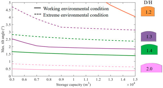
Figure 16.
Maximum tilting angle of double-hull storage tanks (L/D = 1.05).
The ratio L/D is a parameter that controls the tilting motion of the tank. Larger L/D ratios would lead to a smaller tilting motion as the water plane moment of inertia would be increased. However, for the same capacity, larger L/D ratios would also result in more costly use of materials. Figure 17 and Figure 18 show the maximum tilting angles of various floating storage tanks with L/D = 1.1 and 1.2, respectively. As stated earlier, the results reveal that larger L/D ratios reduce the tilting motion of storage tanks. For example, all storage tank capacities considered with D/H ≥ 1.3 satisfy the prescribed stability requirements when L/D is increased from 1.05 to 1.1. As L/D ratio increases further to 1.2, even more slender tanks meet the prescribed stability requirements. As it can be seen from Figure 18, all storage tank capacities considered with D/H ≥ 1.2 now satisfy the prescribed stability requirements. In addition, highly slender tanks with D/H = 1.1 are now able to fulfill the stability requirements provided the storage capacity is greater than 6500 m3.
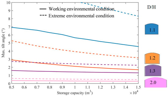
Figure 17.
Maximum tilting angle of double-hull storage tanks (L/D = 1.1).
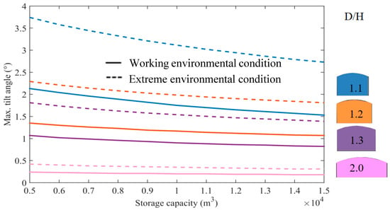
Figure 18.
Maximum tilting angle of double-hull storage tanks (L/D = 1.2).
However, the results presented above are based on a unique set of tank wall thicknesses. Note that the diameter of the tank can range from 20 m for a 5000 m3 tank with D/H = 1.1 to about 40 m for a 15,000 m3 tank with D/H = 2.0. Thus, the tank wall thickness is unlikely to remain the same as D/H ratio and storage capacity vary. The thickness of the tank wall needs to be designed to satisfy strength and serviceability requirements, and this dimension affects the overall mass and hence the tilting motion and stability of the tank. In view of this, it is useful to study the effect of different wall thicknesses on the tilting motion of tanks under both working and extreme environmental conditions.
Figure 19 and Figure 20 present the results showing the effect of wall thickness on the maximum tilting angles of 5000 m3 tank of various D/H ratios under working and extreme environmental conditions, respectively. This tank capacity is chosen as smaller capacity has more stability concerns. Results show that when D/H > 1.3, the maximum tilting angle is virtually independent of tank wall thickness. However, for smaller D/H ratios, the maximum tilting angle tends to increase rapidly when the tank wall thickness reaches a certain critical value. Under a safe working condition, it can be seen from Figure 19 that the stability requirement is violated for D/H < 1.35. However, under an extreme environmental condition, it is noted from Figure 20 that tanks with D/H = 1.3 do satisfy the extreme stability requirement. For extremely slender tanks with D/H = 1.25, the requirement is satisfied only if the wall thickness is smaller than approximately 300 mm.
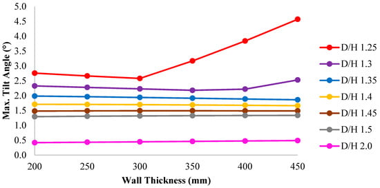
Figure 19.
Effect of wall thickness on tilting angle for 5000 m3 tank (L/D = 1.05) under working environmental condition.
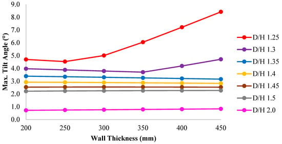
Figure 20.
Effect of wall thickness on tilting angle for 5000 m3 tank (L/D = 1.05) under extreme environmental condition.
A similar study was carried out for 15,000 m3 tanks. As it can be seen in Figure 21 and Figure 22, the maximum tilting angle is not affected by the wall thickness when D/H > 1.25. For smaller D/H ratios such as 1.2 and 1.25, the tilting angle is observed to increase sharply as the wall reaches a critical thickness, similar to the case of the smaller tank capacity considered earlier. It is found that tanks with D/H < 1.3 do not satisfy stability requirements. In view of this, it may be concluded that the stability and tilt motion of the tanks are not affected by the wall thickness provided that the prescribed stability requirements are satisfied.
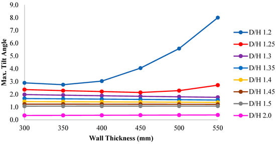
Figure 21.
Effect of wall thickness on tilting angle for 15,000 m3 tank (L/D = 1.05) under working environmental condition.
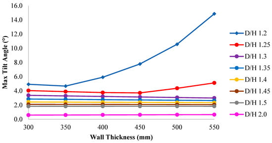
Figure 22.
Effect of wall thickness on tilting angle for 15,000 m3 tank (L/D = 1.05) under extreme environmental condition.
Similar to ships, tanks tend to have low hydrostatic stability and thus large tilt angles under environmental loads when the storage level is either close to empty or fully loaded. When the filling level is low, the free surface effect is predominant as the displaced water volume is small (see Equation (3) for reference). Significant free surface effect reduces the metacentric height and hence the stability of the tank. On the other hand, as the filling level increases, the CG is raised and reaches the highest level when the tank is fully loaded. Thus, the stability of the tank reduces as the filling level increases. Unlike the fully filled condition, a filling level that is close to the fully filled condition would have an additional negative effect of the free surface and it would therefore have lesser stability. Thus, it is important to investigate the stability of tanks under near empty and fully loaded conditions and propose methods to improve the stability of the tanks under these two critical fill conditions.
Figure 23 shows the shape of the inner tank wall, which is segmented into three portions. The heights of the top, middle and bottom portions are denoted as ht, hm, and hb, respectively. The middle segment has a constant radius throughout its height, while the top and bottom segments have a truncated conical shape. This shape aims to improve the stability of tank by reducing the second moment of area of the internal liquid waterplane at both tank top and the bottom segments.
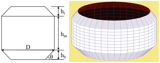
Figure 23.
Inner tank wall with tapering at top and bottom.
Two tanks with a capacity of 5000 m3 and 15,000 m3 are considered to investigate the effect of the tapered inner wall on the stability performance. The dimensions of the tanks are summarized in Table 4. Note that the diameters of the tanks with tapered inner walls are slightly greater than those with cylindrical inner walls. This is to compensate the reduced storage capacity at low and high filling zones so that the overall height of the tank remains the same.

Table 4.
Tank dimensions.
Figure 24 presents the tilting angle of tanks at different fuel filling levels under extreme environmental conditions. As it can be seen, tilting motion tends to be higher when nearly empty or full for the case of a non-tapered tank. In general, it is found that there are two local peaks in the tilting angle corresponding to these two critical filling levels. One of these two levels, depending on the geometry of the tank, would result in the absolute maximum tilting motion. By introducing tapering at the top and bottom segments for the tanks, stability is found to improve for the low and high filling levels. There is a slight reduction in the stability when the fuel level is between the two critical filling levels. This is due to the small increase in the diameter at the middle segment of the tank. However, this drawback is more than compensated by the appreciable decrease in the maximum tilting angle. It is therefore recommended that tapering of the inner tank wall profile be adopted to achieve an improved stability performance.
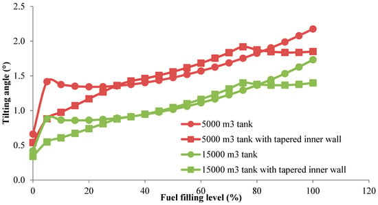
Figure 24.
Effect of tapered inner wall configuration on tilting angle of tanks.
It is important to recognize that a single hull tank design does not provide satisfactory stability under environmental loads. A double hull wall would definitely lead to better stability for the same storage capacity. However, the void between the tank walls means that the outer wall is subject to strong sea water pressure acting on the outer side and the inner wall from stored liquid pressure acting on the inner side. Consequently, these walls would be thicker than the case of a single hull wall which enjoys the benefit of negating pressure on both sides of the wall. To overcome this disadvantage, it would desirable to fill the void between the tank walls with a suitable material, such as sea water or a syntactic foam. Figure 25 shows a proposed design where the space between the double hull is segmented into 8 compartments, all filled with sea water to a desired level. The effect of the sea water level in the void space on the stability performance of the tank will be investigated.

Figure 25.
Plan and side view of tank with sea water between double hulls.
Note that the sea water in the void space also contributes to the free surface effect. The calculation of the section moment of area of the waterplanes of the sea water may be reasonably simplified by assuming zero thickness of stiffeners and sharp corners of the tank wall, as shown in Figure 26. Consequently, the eight water compartments have one typical planar shape with different orientations. The resulting second moments of area corresponding to one typical ballast water compartment are given by
where Ix and Iy denote, respectively, the second moments of area of the ballast water compartment about x- and y-axes, Ix,tri, Iy,tri and Ix,cir, Iy,cir are the second moments of area of the triangle and 1/8 circle illustrated in Figure 26b, respectively.
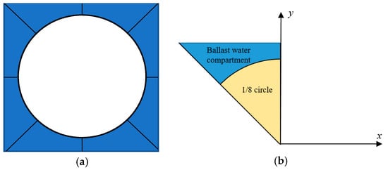
Figure 26.
Simplified model showing tank walls and sea water: (a) planar view and (b) typical compartment.
Table 5 lists the second moments of area of two typical sea water compartments about the center of the entire tank, Ix and Iy, as well as their centers of gravity, xc and yc. Note that in the calculation of free surface effect, the second moment of inertia about its own centroid is needed, which can be easily obtained by using parallel axis theorem. Subsequently, the stability and rotational motion of the floating tanks can be evaluated by including the free surface effect due to the water compartments by using Equation (3).

Table 5.
Second moment of area and center of gravity of sea water compartment.
There are several schemes of filling the compartments between the double hull with sea water. It would be interesting to investigate the effect of the scheme on the performance of the tank with regards to stability and floatability. Figure 27 shows five possible schemes. The sea water level in the compartments is variable for the first four schemes. The level depends on either the hydrocarbon product level only, the average of the draft and hydrocarbon product level, or the draft only. An active control system is therefore needed for these four schemes. For the fifth scheme, the level in the compartments is fixed at half the height of the tank wall. This scheme has the advantage of not requiring a control system.
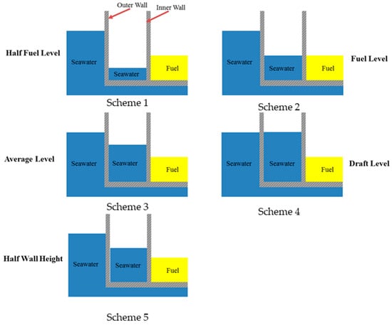
Figure 27.
Sea water filling schemes.
Table 6, Table 7, Table 8 and Table 9 present the results of storage tanks with various aspect ratios and storage capacities under working environmental conditions. Since the infilled sea water reduces the hydrostatic pressure on both tank walls, the wall thickness is assumed to be reduced from 450 mm to 300 mm. The results show the floatability of the tank, i.e., whether it floats or sink, the maximum draft, the maximum tilting angle and the possibility of the tank bottom hitting the seabed. The maximum allowable draft is taken to be 16.5 m. Any draft exceeding the allowable limit may result in potential detrimental environmental effects due to restricted natural flow of sea water within the narrowed gap between tank bottom and seabed. Also, there is a possible danger that the tank bottom may hit the seabed when the tank heaves or rolls under wave action. The allowable limit depends on several factors, including the tank diameter, the tidal, wave and wind conditions and the degree of environmental concern at the site. As previously stated, the maximum limit for the tilting angle for the tank is set to 2 degrees under working environmental condition.

Table 6.
Results of storage tank with D/H = 1.3, L/D = 1.05.

Table 7.
Results of storage tank with D/H = 1.5, L/D = 1.05.

Table 8.
Results of storage tank with D/H = 1.6, L/D = 1.05

Table 9.
Results of storage tank with D/H = 2.0, L/D = 1.05.
When the draft of the tank exceeds the allowable limit, the tank may or may not be floating. In the latter case, the result would show a “sink” value indicating that the tank will sink and rest on the seabed. For convenience, the tank will be referred to as Scheme N tank, where N = 1 to 5, corresponding to the five different schemes for filling the compartments with sea water (see Figure 27). It can be seen from Table 6, Table 7, Table 8 and Table 9 that Schemes 1 and 5 tanks satisfy the design requirements when D/H ≥ 1.6. For the other schemes, the tanks will eventually sink under high fuel load even with a large D/H = 2.0. It is also observed that when D/H = 1.3, any scheme chosen would result in lower maximum tilting angles when compared to the same tank without any filling in the compartments. This implies that the tank stability is improved by filling the compartments with sea water. As D/H ratio increases to 1.6, only Schemes 1 and 5 tanks have maximum tilting angles smaller than tanks without any filling in the compartments. When D/H reaches 2.0, the maximum tilting angle of tanks using any filling scheme will be larger than tanks without any filling. In view of this, it is recommended that Scheme 5 tanks with D/H = 1.6 be adopted as it gives the best performance in terms of stability and it is also most economical since it does not require any active control system.
Figure 28 and Figure 29 show, respectively, the maximum hydrostatic pressure head on the tank outer and inner walls for D/H = 1.6. As it is to be expected, the filling of the compartments with sea water reduces the hydrostatic pressure on the tank’s walls considerably. For example, the half-fuel scheme (Scheme 1) reduces the hydrostatic pressure on outer and inner walls by 42% and 50%, respectively. The corresponding reductions in the constant half-wall scheme (Scheme 5) are 45% and 37%. Both the average-level and full-fuel schemes (Schemes 3 and 2) are able to give even more significant reductions. It is obvious that the draft-level scheme results in no hydrostatic pressure on the outer wall. However, there is less benefit to the inner wall with consequently lesser reduction in the hydrostatic pressure. As a significant volume of sea water is used to fill the compartments in the last three schemes, the additional heavy weight of the contained sea water will lead to reduced storage capacity and hence an uneconomical tank design.
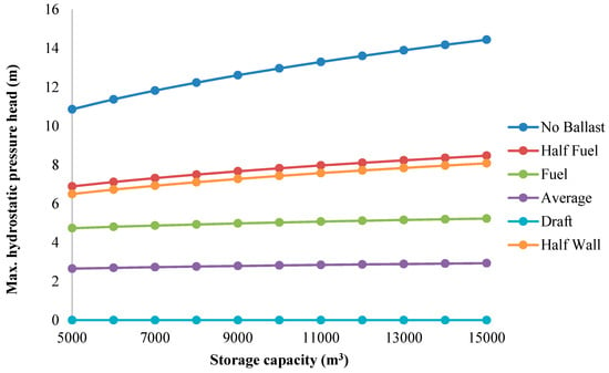
Figure 28.
Maximum hydrostatic pressure head on outer tank wall.
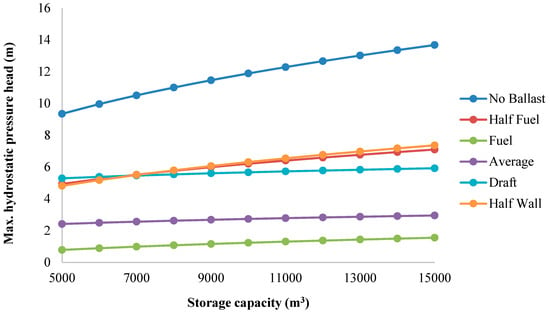
Figure 29.
Maximum hydrostatic pressure head on inner tank wall.
In an attempt to obtain a significant reduction in hydrostatic pressure without compromising the designed storage capacity, it is worthwhile to explore filling the compartments with durable and light-weight (about 332 kg/m3) composite syntactic foam. The foam comprises composite hollow microspheres that are bonded together with syntactic foam. The material can have a minimum life of 40 years with a maximum 5% loss of buoyancy throughout its lifespan [31]. Figure 30 illustrates the use of syntactic foam to fill the compartments. The slab beneath the compartments has holes or slits to allow seawater to flow through to serve the purpose of balancing the hydrostatic pressure acting on both sides of each wall. Gaps between the tank walls and the foam are provided in order to allow the flow of seawater.
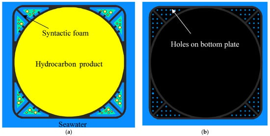
Figure 30.
Use of syntactic foam as floaters: (a) configuration and (b) bottom plate.
Figure 31 presents the maximum tilting angles of storage tanks with syntactic foam under working environmental conditions. All tank walls are assumed to be 300 mm thick. Curves highlighted in red denote that the maximum draft of the tank has exceeded the allowable limit of 16.5 m. Conversely, other curves denote that the maximum draft meets the allowable limit requirement. As it can be seen, the results show that slender tanks (smaller D/H ratio) will result in larger draft for a given storage capacity, as to be expected. For a given tank D/H ratio, larger storage tanks may violate the draft limit requirement. On the other hand, smaller storage tanks may not meet the stability or tilting limit requirement. Figure 31 shows that for the entire range of storage capacities considered, it is necessary that the tank D/H ≥ 1.6 to ensure that the tank is stable and the limits on draft and tilting angle are not exceeded.
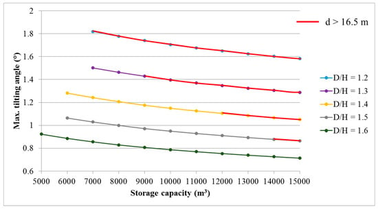
Figure 31.
Maximum tilting angle of floating tanks with syntactic foam.
The syntactic foam filling scheme, just like the sea water filling schemes discussed earlier, will result in reduction of the maximum hydrostatic pressures at the tank walls. The reduction in pressures are presented in Figure 32. Figure 32a shows the variations of the maximum hydrostatic pressure head (ΔH) on tank inner wall with respect to storage capacity. Figure 32b shows the percentage reduction, as compared to the tank with no filling scheme. It can be seen from Figure 32a that the maximum pressure head increases with storage capacity but reduces with increasing D/H. When compared to the tank with no filling scheme, Figure 32b shows there is at least 43% reduction in the maximum ΔH for a 5000 m3 tank. When the storage capacity increases to 15,000 m3, the reduction increases to as high as 55%. Furthermore, it can be observed from Figure 32b that this percentage reduction in ΔH is found to be virtually independent of D/H. The effect of syntactic foam filling scheme is more pronounced with respect to the outer wall. Owing to the free flow of sea water to within the gap between tank walls and syntactic foam, the level attained within the compartment will be at the draft level. Consequently, there is no net pressure effect on the outer wall.
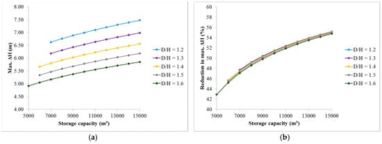
Figure 32.
Hydrostatic pressure on tank inner wall: (a) maximum pressure head and (b) reduction in maximum pressure head.
An alternative to using ballast water or syntactic foam for reducing hydrostatic pressures on tank walls is to consider using a single hull cylindrical storage tank. It is obvious that a single hull tank would enjoy the benefit of nearly balanced pressure on both sides of the wall. However, there is a need to examine carefully the stability and floatability of the tank of the same storage capacity as a double hull tank. Figure 33 presents a single hull cylindrical tank held in lateral position by surrounding barges and spacers. Rubber fenders are provided to absorb the kinetic energy to prevent damage to tank wall and barge.
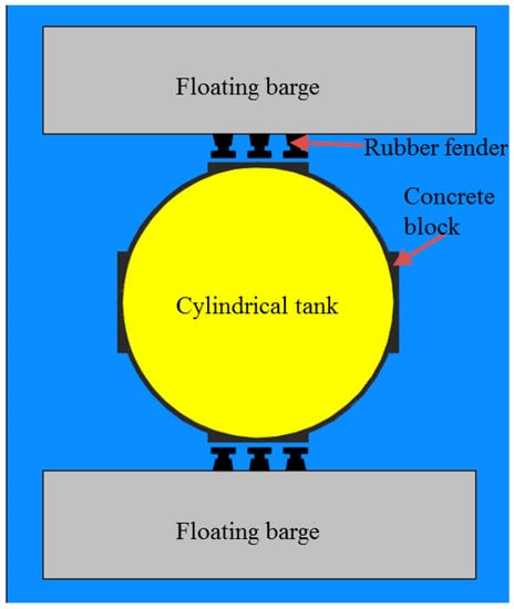
Figure 33.
Single hull tank enclosed by floating barges.
Figure 34 shows the maximum tilting angle of single wall cylindrical tanks under wind and current loads at their 1-year return period. As in earlier cases, a relatively thinner 300 mm wall is assumed which is deemed feasible in view of the balanced hydrostatic pressures on the tank wall. Results show that tanks with D/H = 1.7 fulfill the stability and operational requirements on tilting motion when the storage capacity is above 10,500 m3. Tanks of all storage capacities considered in the study satisfy the aforementioned design checks provided D/H ≥ 1.8.
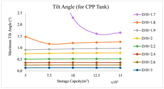
Figure 34.
Maximum tilting angle of single hull cylindrical tank (5000–17,500 m3).
The maximum hydrostatic pressure on the tank wall is shown in Figure 35. It is interesting to note that the maximum hydrostatic pressure head is below 2 m when the tank D/H > 1.8. These pressure head values are found to be much smaller than those for double hull tanks with compartment filled with water or syntactic foam. Results also reveal that the maximum ΔH occurs when the tank is empty. As the single hull tank generally would result in a lighter weight design, as compared to double hull tank, the draft experience would be smaller. Consequently, the maximum hydrostatic pressure exerted on the wall would be smaller.
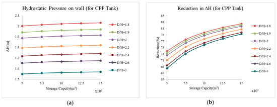
Figure 35.
Hydrostatic pressure on cylindrical tank wall: (a) maximum pressure head and (b) reduction in maximum pressure head.
The single hull tank has the advantages of easy construction, lesser construction material and smaller hydrostatic pressure difference on the tank wall. However, this concept suffers from lesser stability and buoyancy as compared to a double hull tank of same storage capacity. For this reason, a larger D/H ratio of about 1.8 is necessary in order to fulfill the prescribed stability requirements. This would result in a greater use of sea space as compared to the other alternative concepts. In order to improve the single hull tank design concept, it is proposed to attach four smaller hollow cylinders to the exterior of the tank wall, as shown in Figure 36. These hollow cylinders are made of the same lightweight concrete as the storage tank and are intended to act as floaters, i.e., to provide additional buoyancy. In addition, these floaters are also designed to interact with the rubber fenders installed on the sides of the floating barges. The merits of this design include feasible and easy construction, balanced hydrostatic pressure and relatively low construction cost. Results plotted in Figure 37 show that a D/H ratio of 1.6 satisfies the prescribed stability requirement and motion criteria.
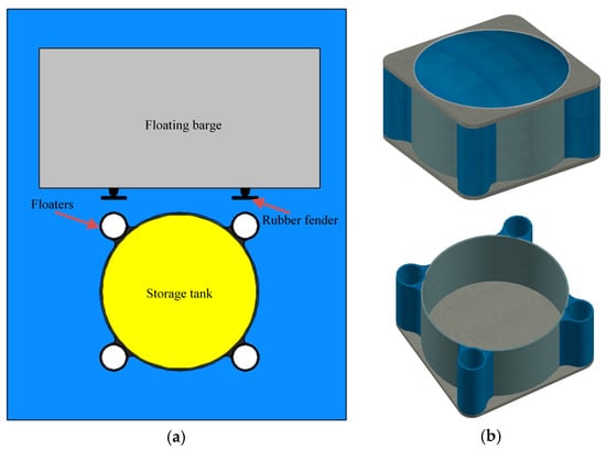
Figure 36.
Single hull tank with four hollow cylindrical floaters: (a) plan view and (b) isometric view.
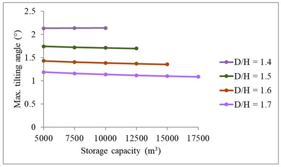
Figure 37.
Maximum tilting angle of single hull cylindrical tank (5000–17,500 m3) under working environmental conditions.
4. Discussion
A study on the hydrostatic stability analyses of floating hydrocarbon storage tanks with various storage capacities ranging from 5000 m3 to 17,500 m3 has been carried out. Various tank designs were investigated. Static analysis of tank tilting angle under sustained wind and current loads was carried out. Note that both 1-year and 100-year environmental conditions listed in Table 3 are employed to define the working and extreme environmental conditions. In the evaluation of hydrostatic performance of the proposed tank designs, the acceptable tank rotational motion is limited to 2° and 5°, respectively. The maximum draft of tanks is set to 16.5 m to avoid undesirable contact between the tank bottom and seabed in view of the shallow water depth in Singapore coastal regions. The local wave conditions are generally benign and thus their effect on the tanks are not considered in the study.
Wind loads also contain dynamic components that may give rise to sloshing of hydrocarbon product inside the storage tanks. In order to evaluate the effect of dynamic wind loads, the fundamental tank sloshing period was first identified to be in the range of 8–10 s [32]. The peak energy of short-term oscillatory wind is, however, normally located at a period above 1 min [33]. As a result, the dynamic wind energy at tank sloshing period is expected to be small. Thus, it is reasonable to neglect the dynamic effect of wind loads.
In addition to wind, the flow of water current passing through a floating tank forms vortex shedding in the downstream, which may also give rise to excitation of sloshing. The frequency of vortex shedding may be evaluated by using
where St is the Strouhal number and can be reasonably taken as 0.2 [34], fv the frequency of vortex shedding, Do the overall diameter of the tank, and vc the current speed. Based on the tank dimension considered and the current speed listed in Table 3, the period of vortex shedding is expected to be ranging from 75 s to 140 s. Again, this is much greater than the aforementioned sloshing periods. Therefore, it is justifiable to neglect the dynamic effect of water current loads in the study.
St = fv Do/vc,
The following conclusions may be drawn from the study:
- Larger storage tanks have better stability than smaller tanks due to the larger restoring moment of inertia.
- Based on the environmental data at the selected site, the double hull tank with L/D =1.05 shall have a D/H ≥ 1.3 to ensure a stable and economical design.
- For a given storage capacity, tank stability may be improved by choosing tank dimensions with as large as practically possible L/D and D/H ratios. However, large L/D ratio results in high cost due to additional construction materials whereas large D/H ratio leads to use of more sea space.
- Once the prescribed stability requirements have been fulfilled, the thickness of tank walls has negligible effect on the stability of the tank.
Tanks tend to have the lowest stability when the fuel level is either very low or very high. Stability may be improved by adopting tapered inner wall profile.
The double hull arrangement requires thick walls to resist high hydrostatic pressures due to pressure acting on one face of each wall. In order to achieve an economical design, it is necessary to reduce the effect of unbalanced hydrostatic pressures. Four design proposals are considered. The first two proposes to fill the tank compartments with (1) sea water or (2) composite syntactic foam. The third requires redesigning the cylindrical tank, as a single wall and the fourth is a modification by attaching hollow cylindrical floaters to the exterior of the tank wall.
In the first proposal, five different sea water filling schemes were investigated. All the five schemes are found to significantly reduce the effect of hydrostatic pressure acting on the tank walls. The “half wall height” filling scheme is recommended as it does not require any control system. A minimum D/H ratio of 1.6 is needed to ensure the stability of the tank. The disadvantage of this proposal is that the addition of sea water in the tank compartments increases the weight of the storage tanks substantially. Thus, the floatability of the storage tanks is significantly decreased, which reduces the tank storage capacity.
The second proposal employs light-weight composite syntactic foam to fill the tank compartments, which alleviates the problem due to the extra weight of filling sea water suffered in the first proposal. A minimum D/H ratio of 1.6 is suggested for tanks with durable and light-weight syntactic foam. Though the use of syntactic foam appears superior, it is significantly more expensive than the use of sea water as filling material.
Single wall tanks were also examined as the third proposal. This proposal enjoys the advantage of nearly balanced hydrostatic pressure acting on both sides of the tank wall. However, it has a low stability. Consequently, a minimum D/H ratio of 1.8 is required, which leads to the need for a larger sea space.
The fourth proposal improved the single wall tank design by attaching four concrete floaters to the tank wall. Results show that a D/H ratio of 1.6 satisfies the prescribed stability requirement and motion criteria. In addition to increasing the buoyancy of the tank, the floaters are also designed to interact with the rubber fenders installed on the sides of the floating barges. They are relatively small in size when compared to the single wall tank. Thus, they do not introduce significant increase in the construction cost.
The maximum allowable rotation of the tank is limited to 5° under extreme environmental conditions. This matches with the comprehensive hydrodynamic analysis results presented in references [13,14]. Within such a small rotation range, the investigation on the initial stability is therefore deemed sufficient in an initial feasibility study phase. However, unexpected large tank rotation may occur accidentally. Undesirable damage to the floating tanks may also affect the stability. More detailed studies are thus needed to examine the stability curve and damaged stability of the proposed storage tanks.
5. Conclusions
This paper presents a novel stand-alone floating hydrocarbon storage and bunkering facility to cope with the growth in the demand for hydrocarbon storage and the shortage of available land for such storage facilities. The facility can be easily scaled up and down to suit any sea space and required storage capacity. It also has the advantage of mobility, as it can be relocated to another location if necessary. Inside the facility, there are self-stabilizing floating storage tanks of various storage capacities to cater for the operators’ commercial needs. These tanks have many advantages such as modular design for easy construction, and easy maintenance, as well as replacement.
Owing to the lack of design specifications for floating fuel storage tanks, codes of practice for both onshore tanks and offshore tankers were reviewed. Based on the review, design guidelines for stability and motion criteria of floating tanks under both working and extreme environmental conditions were established.
Different tank structural configurations were proposed and a comprehensive study on the hydrostatic performance of the tank designs was carried out. The most appealing design is a single wall cylindrical tank with floaters attached to the tank wall. The merits of this design include feasible and easy construction, balanced hydrostatic pressure and relatively low construction cost. Results from a hydrostatic analysis on a practical range of storage capacities show that these self-stabilizing tanks are very doable in calm water zones. Results also suggest that the tank shall have a D/H ratio of at least 1.6 to furnish a stable and economical design in Singapore coastal waters.
Finally, it is worth mentioning that although the present study is based on Singapore environmental conditions, the proposed concept is deemed to be applicable to coastal waters in other parts of the world with appropriate considerations of local conditions.
6. Patent
Wang, C.M.; Ang, K.K.; Dai, J.; Lim, B.K.; Magee, A.R.; Watn, A.; Hellan, Ø.; Lie, H.; Justnes, H.; Tan, T.L.; Heah, S.P.; Lee, E.Y. Floating hydrocarbon storage and bunker facility. Singapore provisional patent, No. 10201702691X.
Author Contributions
Conceptualization, J.D., K.K.A., C.M.W., Ø.H. and A.W.; methodology, J.D. and J.J.; formal analysis, J.D. and J.J.; writing—original draft preparation, J.D.; writing—review and editing, K.K.A., C.M.W., Ø.H. and A.W.; visualization, J.D.; funding acquisition, C.M.W.
Funding
This research is supported in part by the Singapore Ministry of National Development and the National Research Foundation, Prime Minister’s Office under the Land and Liveability National Innovation Challenge (L2 NIC) Research Programme (L2 NIC Award No L2 NICTDF1-2015-2.). Any opinions, findings, and conclusions or recommendations expressed in this material are those of the author(s) and do not reflect the views of the Singapore Ministry of National Development and National Research Foundation, Prime Minister’s Office, Singapore.
Acknowledgments
The support from JTC Corporation is deeply appreciated by the authors.
Conflicts of Interest
The authors declare no conflict of interest. The funders had no role in the design of the study; in the collection, analyses, or interpretation of data; in the writing of the manuscript. The funders have given approval to publish the results.
References
- Curtis, L.B.; Shepler, J.C. Dubai Khazzan—Pioneer of large undersea storage systems. J. Petrol. Technol. 1970, 22, 1065–1075. [Google Scholar] [CrossRef]
- Galbraith, D.N. Beryl Alpha—Condeep GBS analysis. Society of Petroleum Engineers. In Proceedings of the Offshore Europe Conference, Aberdeen, UK, 7–10 September 1993. [Google Scholar]
- Oljemuseum, N. Troll A Platform. Available online: https://www.norskolje.museum.no/wp-content/uploads/2016/02/2338_f832073aff564639ac0993cb0545e8cf.jpg (accessed on 30 July 2019).
- Hirata, H. Floating Oil Storage Installation. U.S. Patent No. 3,779,193, 18 December 1973. [Google Scholar]
- ISSC Committee. Very large floating structures. In Proceedings of the 16th International Ship and Offshore Structures Congress, Southampton, UK, 20–25 August 2006; Volume 2, pp. 391–442. [Google Scholar]
- Collet, P.; Vaucquelin, N.; Bury, A. Floating concrete barge assessment and inspection plan: N’KOSSA case study, a large pre-stressed concrete floating production unit in operation in Congo. In Proceedings of the ASME 33rd International Conference on Ocean, Offshore and Arctic Engineering, San Francisco, CA, USA, 8–13 June 2014. [Google Scholar]
- Ueda, S. Floating oil storage base. In Large Floating Structures: Technological Advances; Wang, C.M., Wang, B.T., Eds.; Springer: Singapore, 2015; pp. 91–105. [Google Scholar]
- Oil&Gas Journal. Guide to World Crudes: Total Updates Assay for Congolese N’Kossa. Available online: https://www.ogj.com/drilling-production/drilling-operations/article/17232666/guide-to-world-crudes-total-updates-assay-for-congolese-nkossa (accessed on 30 July 2019).
- Wang, C.M.; Ang, K.K.; Dai, J.; Lim, B.K.; Magee, A.R.; Watn, A.; Hellan, Ø.; Lie, H.; Justnes, H.; Tan, T.L.; et al. Floating Hydrocarbon Storage and Bunker Facility. Singapore Provisional Patent No. 10201702691X, 17 April 2017. [Google Scholar]
- Dai, J.; Wang, C.M.; Utsunomiya, T.; Duan, W. Review of recent research and developments on floating breakwaters. Ocean Eng. 2018, 158, 132–151. [Google Scholar] [CrossRef]
- Tay, Z.Y.; Wang, C.M.; Utsunomiya, T. Hydroelastic responses and interactions of floating fuel storage modules placed side-by-side with floating breakwaters. Mar. Struct. 2009, 22, 633–658. [Google Scholar] [CrossRef]
- Wan, L.; Han, M.; Jin, J.; Zhang, C.; Magee, A.R.; Hellan, Ø.; Wang, C.M. Global dynamic response analysis of oil storage tank in finite water depth: Focusing on fender mooring system parameter design. Ocean Eng. 2018, 148, 247–262. [Google Scholar] [CrossRef]
- Zhang, C.; Wan, L.; Magee, A.R.; Han, M.; Jin, J.; Ang, K.K.; Hellan, Ø. Experimental and numerical study on the hydrodynamic loads on a single floating hydrocarbon storage tank and its dynamic responses. Ocean Eng. 2019, 183, 437–452. [Google Scholar] [CrossRef]
- Wan, L.; Zhang, C.; Magee, A.R.; Jin, J.; Han, M.; Ang, K.K.; Hellan, Ø. An innovative mooring system for floating storage tanks and stochastic dynamic response analysis. Ocean Eng. 2018, 170, 361–373. [Google Scholar] [CrossRef]
- Jiang, D.; Tan, K.H.; Dai, J.; Ong, K.C.G.; Heng, S. Structural performance evaluation of innovative prestressed concrete floating fuel storage tanks. Struct. Concr. 2019, 20, 15–31. [Google Scholar] [CrossRef]
- Dai, J.; Ang, K.K.; Zhang, C. Hydroelastic analysis of modular floating barges for hydrocarbon storage facility. In Proceedings of the 1st Vietnam Symposium on Advances in Offshore Engineering, Hanoi, Vietnam, 1–3 November 2018. [Google Scholar]
- API. API 653: Tank Inspection, Repair, Alteration, and Reconstruction, 3rd ed.; American Petroleum Institute: Washington, DC, USA, 2001. [Google Scholar]
- EEMUA. EEMUA 159: Above Ground Flat Bottomed Storage Tanks—A Guide to Inspection, Maintenance and Repair, 4th ed.; Engineering Equipment Material Users Association: London, UK, 2014. [Google Scholar]
- DNV. Rules for classification of ships. In Part 3 Chapter 4: Stability and Watertight Integrity; Det Norske Veritas: Oslo, Norway, 1995. [Google Scholar]
- MARPOL. Annex I: Regulations for the Prevention of Pollution by Oil; The International Convention for the Prevention of Pollution from Ships; International Maritime Organization: London, UK, 1983. [Google Scholar]
- SS. SS 532: 2016: Code of Practice for the Storage of Flammable Liquids; Singapore Standards: Singapore, 2016. [Google Scholar]
- NUS; SINTEF. Behavior of Barge Structure under Ship Impact; MPFS Project Report No. 16 Issued to JTC Corporation; National University of Singapore: Singapore, 2018. [Google Scholar]
- Elzinga, T.; Iribarren, J.R.; Jensen, O.J. Movements of moored ships in harbours. In Proceedings of the 23rd International Conference on Coastal Engineering, Venice, Italy, 4–9 October 1992; pp. 3216–3229. [Google Scholar]
- Jensen, O.J.; Viggosson, G.; Thomsen, J.; Bjordal, S.; Lundgren, J. Criteria for ship movements in harbours. In Proceedings of the 22nd International Conference on Coastal Engineering, Delft, The Netherlands, 2–6 July 1990. [Google Scholar]
- DNV. DNV-OS-C301: Stability and Watertight Integrity; Det Norske Veritas: Oslo, Norway, 2011. [Google Scholar]
- DNV. DNV-RP-H103: Modelling and Analysis of Marine Operations; Det Norske Veritas: Oslo, Norway, 2011. [Google Scholar]
- DNV. DNV-RP-C205: Environmental Conditions and Environmental Loads; Det Norske Veritas: Oslo, Norway, 2010. [Google Scholar]
- API. API PR 2A-WSD: Recommended Practice for Planning, Designing and Constructing Fixed Offshore Platforms—Working Stress Design, 21st ed.; American Petroleum Institute: Washington, DC, USA, 2007. [Google Scholar]
- SINTEF; NUS. Guidelines and Recommendations for Moored Floating Structures in Singapore; MPFS Project Report Issued to JTC Corporation; National University of Singapore: Singapore, 2019. [Google Scholar]
- Tkalich, P.; Vethamony, P.; Luu, Q.-H.; Babu, M.T. Sea level trend and variability in the Singapore Strait. Ocean Sci. 2013, 9, 293–300. [Google Scholar] [CrossRef]
- Aberle, G.E.; Christensen, L. Mid depth buoys design for long life using syntactic foam buoyancy, redundant and replaceable tether systems. In Proceedings of the Offshore Technology Conference Asia, Kuala Lumpur, Malaysia, 22–25 March 2016. [Google Scholar]
- NUS; SINTEF. Design Premises and Analyses of Hydrocarbon Storage Tanks; MPFS Project Report No. 5 Issued to JTC Corporation; National University of Singapore: Singapore, 2016. [Google Scholar]
- Van der Hoven, I. Power spectrum of horizontal wind speed in the frequency range from 0.0007 to 900 cycles per hour. J. Meteorol. 1957, 14, 160–164. [Google Scholar] [CrossRef]
- Jiang, H.; Cheng, L. Strouhal-Reynolds number relationship for flow past a circular cylinder. J. Fluid Mech. 2017, 832, 170–188. [Google Scholar] [CrossRef]
© 2019 by the authors. Licensee MDPI, Basel, Switzerland. This article is an open access article distributed under the terms and conditions of the Creative Commons Attribution (CC BY) license (http://creativecommons.org/licenses/by/4.0/).

