Abstract
This paper presents an analysis of a new application of different direct matrix converter topologies used as power interfaces in AC, DC, and hybrid microgrids, with model predictive current control. Such a combination of a converter and control strategy leads to a high power quality microgrid voltage, even with a low power quality main grid voltage and even during the connection and disconnection of a variety of loads and generation sources to the microgrids. These robust systems are suitable for applications in which sensitive loads are to be supplied and these loads are connected close to distributed-generation sources with inherent intermittent behavior. The authors also propose the use of new direct matrix converter configurations with a reduced number of switches in order to achieve reduced cost, reduced failure rate, and higher reliability, which are very desirable in microgrids. Finally, the authors also introduce new hybrid direct matrix converter topologies that provide interesting options for the islanded operation of the microgrids with the use of a battery system. In other words, the proposed hybrid direct matrix converters result in flexible hybrid microgrid configurations integrating DC and AC devices with high power quality and high power supply reliability.
1. Introduction
Over the years, many works related to microgrids have been developed aiming at improving the operation of modern electrical systems with high penetration of distributed generation [1,2,3,4,5,6]. AC microgrids have their inherent operational drawbacks such as the presence of harmonic currents and voltages, frequency regulation, and reactive power issues [4,5,6]. On the other hand, DC microgrids are able to overcome those mentioned operational issues and, thus, present less complexity and are more easily operated. Furthermore, DC microgrids allow for a more friendly integration with systems such as photovoltaic generation, batteries, and electronic loads [5,7,8]. Hybrid microgrids are a great solution to integrate the AC and DC systems and devices, taking advantage of the benefits of AC and DC microgrids [9,10,11].
The concept of microgrid is many times related to electrical systems operating in remote regions feeding small villages [12], sometimes isolated from the main power system [13,14], or even related to applications in ships [15,16], airplanes, and other types of vehicles. Such applications usually require high reliability and low weight. Furthermore, a system with a low maintenance necessity is desired.
The Matrix Converter (MC) was proposed many years ago as a solution with a simple and compact power circuit and with high power density. Besides, the absence of the bulky and sensitive DC-link capacitors along with the reduced voltage stress applied to the switches could lead to a higher lifetime and higher reliability of the system [17,18,19,20,21], which are very desirable in microgrid applications. Some of the main drawbacks of the MCs are the high number of power semiconductors [17], besides the high complexity of their modulation techniques [19].
In order to overcome the high number of employed switches, some papers proposed the use of new topologies with a reduced number of switches such as the Sparse Matrix Converter (SMC), the Very Sparse Matrix Converter (VSMC), and the Ultra Sparse Matrix Converter (USMC) [22,23]. In this paper, the authors present new converter topologies that offer a reduced number of overall semiconductor devices in comparison to the SMC, the VSMC, and the USMC.
Recently, many researchers have developed works related to Model Predictive Control (MPC), which is an excellent option to simplify the MC operation, since this control technique directly activates the converter switches, with no need for modulation, besides presenting many other advantages such as fast dynamic response [24,25]. In other words, many works [17,18,21] reported the complexity of operating MCs with modulation techniques such as the Venturini method and the space-vector modulation. The MPC sends firing signals to the switches, bypassing the complex modulation.
Thus, with those topological and control advances, MC applications are coming back as a trending topic in recent research. The combination of MCs with MPC has been widely used in wind power applications [26,27,28,29,30]. Other modern applications of MCs are in motor drives, electric vehicles, and energy storage [31,32,33,34,35,36,37]. The use of MCs in AC, DC, and hybrid microgrids is particularly new, and only a few papers have developed some analysis of this application. In [33], the possibility of using the 3 × 3 Direct Matrix Converter (DMC) was explored in a wide range of possible connections such as AC-AC, AC-DC, DC-AC, and DC-DC.
In [37], the idea studied in the present paper was first introduced, which was to use a DMC as a power interface in microgrids using MPC. In other words, the converter is responsible for synthesizing a high power quality microgrid voltage, while absorbing/injecting power from/into the main grid. In [37], many different operation cases were studied, and experimental results were presented. However, only the AC-AC 3 × 3 DMC was analyzed in an AC microgrid.
The main contributions of this paper are summarized as follows:
1. The application of a DMC with MPC as a power interface is proposed not only for AC microgrids, but also for DC and hybrid microgrids;
2. Two new DMC topologies with a reduced number of switches, applied as power interfaces in AC and DC microgrids, are proposed. The first one (called AC-AC 2 × 3 DMC) allows synthesizing the AC-microgrid three-phase voltage using only two phases of the three-phase grid voltage. The second one (called AC-DC 2 × 2 DMC) allows synthesizing the DC-microgrid voltage using only two phases of the three-phase grid voltage. Since one of the grid voltage phases is not used, the number of semiconductors required in the converters is decreased, leading to the reduction of the systems’ cost and to an overall failure rate reduction. Besides, the systems’ reliability is increased since even with the eventual loss of one of the grid voltage phases, due to a fault, the microgrid power supply can be maintained using the other two available phases of the grid voltage. The authors acknowledge that many papers have been published proposing different MCs with different numbers of input and output terminals [38,39,40,41,42]. However, the converters proposed in the present paper have an extra important feature, which is to use the contactors , , , and to improve the system’s power supply reliability by alternating between different phases of the main grid voltage, in case of the occurrence of faults. This is an essential feature to create a high power quality microgrid topology with high reliability, capable of supplying power to critical loads;
3. Two novel DMC topologies (the hybrid DMC and the reduced hybrid DMC) that can be applied to hybrid microgrids are introduced. These new microgrid configurations can integrate DC and AC energy sources and loads, adding new options for islanded mode operation and increasing the power-supply reliability.
All the topologies are able to maintain a high power quality microgrid voltage, despite the grid voltage power quality and despite the types of loads and generation sources connected to this microgrid. This is a very interesting feature for systems with the presence of distributed generation, operating in remote areas connected to a low power quality grid. The authors intend to propose new converter topologies with low cost, low failure rate, high reliability, high efficiency and high lifespan. These goals are achieved due to the absence of the sensitive DC-link capacitors in DMCs, due to the reduction of the number of switches, and due to the possibility of operating disconnected from the main grid. It is important to emphasize that reducing the number of switches could potentially reduce the failure rates. However, current stress might be an observed issue, which could deteriorate the converter reliability.
2. Different Direct Matrix Converter Topologies for Microgrid Applications
2.1. AC-AC 3 × 3 DMC
The first topology analyzed in this paper was first used for the power interface application in [37], which is composed of an AC-AC 3 × 3 DMC, using nine bidirectional switches, as shown in Figure 1a. This converter uses the three-phase input voltage in order to synthesize the desired high power quality output voltage , which supplies a given AC microgrid.
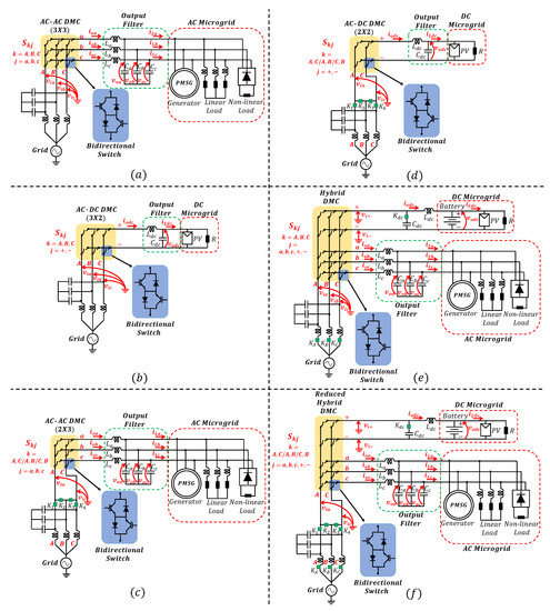
Figure 1.
DMC topologies. (a) AC-AC 3 × 3, (b) AC-DC 3 × 2, (c) AC-AC 2 × 3, (d) AC-DC 2 × 2, (e) hybrid DMC, and (f) reduced hybrid DMC.
2.2. AC-DC 3 × 2 DMC
The second topology analyzed in this paper is the AC-DC 3 × 2 DMC, which uses six bidirectional switches in order to supply a DC microgrid, as shown in Figure 1b. This topology uses the three input voltages to generate the DC output voltage . The authors acknowledge the previous use of this topology in applications such as battery State Of Charge (SOC) control [31]. To the authors’ knowledge, the power interface between the AC main grid and a given DC microgrid is a new application of such a topology.
2.3. AC-AC 2 × 3 DMC
The authors propose a new DMC topology that is able to supply a three-phase AC microgrid using only two phases of the three-phase input voltage. This topology, along with the control used, can both reduce the system’s overall cost and increase the system’s reliability.
The cost reduction is due to the use of only six bidirectional switches instead of nine, as in the topology shown in Figure 1a, meaning a reduction of six IGBTs and of six diodes.
From the reliability point of view, if the three phases of the three-phase input voltage are available, one can synthesize the output voltage using, for example, phases A and C, as shown in Figure 1c. If, for instance, a fault occurs is phase C, the DMC can synthesize the output voltage using phases A and B. In other words, one can use the contactors , , , and to select any input-voltage phase combination, as long as any two different phases of the grid voltage are connected to the two DMC’s input terminals.
It is important to notice that this topology has the same number of switches of a conventional three-phase, two-level back-to-back converter (twelve IGBTs plus twelve diodes) that could be used for this application. The proposed topology, however, might present lower cost and higher reliability due to the absence of the bulky and sensitive DC-link capacitors, besides the fact that the DMC switches suffer less voltage stress, as previously mentioned, reducing failure rates.
Furthermore, this topology also results in a smaller number of overall semiconductor devices (twelve IGBTs plus twelve diodes) in comparison to other AC-AC MCs with a reduced number of switches such as the SMC (fifteen IGBTs plus eighteen diodes), the VSMC (twelve IGBTs plus thirty diodes), and the USMC (nine IGBTs plus nineteen diodes).
2.4. AC-DC 2 × 2 DMC
Similarly to the previous case, it is also possible to synthesize a DC voltage, in order to supply a DC microgrid, using only two phases of the three-phase input voltage, as depicted in Figure 1d. This topology has only four bidirectional switches, resulting in a reduction of four IGBTs and of four diodes in comparison to the topology presented in Figure 1b.
2.5. Hybrid DMC
The authors also propose a new topology called hybrid DMC that can supply power to AC and DC microgrids, simultaneously. Besides, this topology allows for the system’s islanded operation in case of the loss of the main grid. This configuration is depicted in Figure 1e.
The Hybrid DMC is simply the combination of the topologies shown in Figure 1a,b in the same structure. In normal operation mode, the AC-AC 3 × 3 DMC regulates the AC microgrid voltage. In this case, however, the AC-DC 3 × 2 DMC controls the SOC of a battery system present in the DC microgrid, instead of controlling a DC capacitor voltage.
When a fault is detected in the main grid, the system can start operating in islanded mode. Thus, the contactors , , and must open, keeping the system isolated from the main grid. At this moment, the switches , , and must be kept closed, and the AC-DC 3 × 2 DMC stops regulating the battery SOC and becomes a DC-AC 2 × 3 DMC, which is responsible for regulating the AC microgrid voltage , with the battery working as a DC voltage source that both serves as an input for the DMC and maintains the DC microgrid voltage regulated, while the battery SOC remains within its constant-voltage region.
Moreover, the contactor must be closed in order to connect the capacitor to the system, forming a current input filter that does not allow that the converter’s switched current flows towards the DC microgrid, when in islanded operation mode.
Thus, the authors propose a new topology with the absence of DC capacitors in order to increase the system’s reliability and lifespan. This topology does not have a DC link and only needs a small DC capacitor, as a current filter, that is not essential for the system operation. This capacitor is only connected in special cases and does not suffer much voltage stress.
2.6. Reduced Hybrid DMC
Finally, the authors propose the reduced hybrid DMC as depicted in Figure 1f. This system is able to operate in the exact same way as the hybrid DMC, shown in Figure 1e, but it is a more economical solution, with a reduced number of switches. In other words, this topology is composed of the DMCs shown in Figure 1c,d, and it results in a converter with ten bidirectional switches, which means a reduction of ten IGBTs and ten diodes in comparison to the hybrid DMC.
In the islanded operation mode, the switches and must be kept closed, and the AC-AC 2 × 3 DMC keeps regulating the AC microgrid voltage , but with the positive and negative DC voltages as inputs (imposed by the battery), instead of the phases A and C of the grid voltage. This is the same as in the hybrid DMC operating in the islanded mode.
3. Control Diagrams
The control strategy adopted in this work is based on two control loops: an outer voltage control loop using PI controllers and an inner current control loop using MPC. The only exceptions are in the cases in which there is a battery system replacing the DC capacitor (hybrid DMC and reduced hybrid DMC). In such cases, instead of an outer voltage control loop, there is an outer SOC control loop. All the control strategies are depicted in Figure 2. In all cases, either the voltage control or the SOC control generates a current reference that is provided to the MPC. The MPC details are further discussed in Section 5. For the AC microgrid cases, the voltage control loop is executed in a -rotating reference frame aligned with the input-voltage angle . In order to obtain this angle, the PLL circuit used is the positive-sequence detector presented in [43]. The positive-sequence detector is able to extract the positive-sequence fundamental-component of a voltage along with its angle.
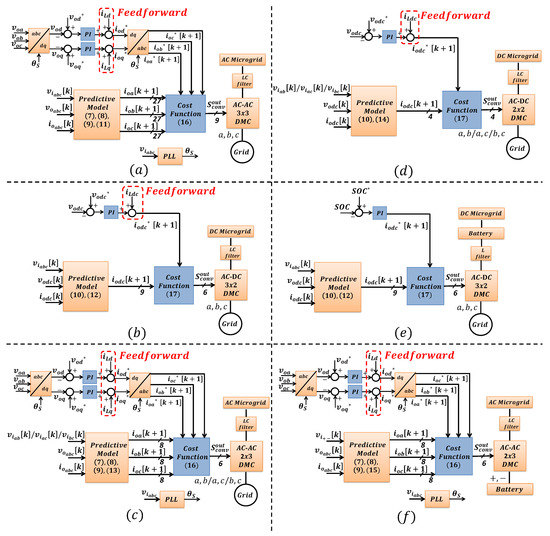
Figure 2.
Control diagrams. (a) AC-AC 3 × 3, (b) AC-DC 3 × 2, (c) AC-AC 2 × 3, (d) AC-DC 2 × 2, (e) SOC control in hybrid DMC, and (f) hybrid DMC in islanded operation.
The feedforward term, which is common to almost every control strategy, is essential for the maintenance of high power quality output voltages. This term is responsible for rejecting disturbances related to the connection and disconnection of loads and generation sources in the microgrids.
An important fact known about the DMC operation is that some switching restrictions are required for its proper operation [17,18,19]. In other words, in order to avoid short circuits, since the converter is fed by a voltage source, no two input terminals can be connected, simultaneously, to the same output terminal. Besides, there must always be a path for the load current to flow through, meaning that, in every sampling step, one of the input terminals must be connected to each of the output terminals. For example, in the case of the AC-AC 3 × 3 DMC (see Figure 1a), these switching restrictions can be summarized as: , in which a given switch assumes State 0 if it is open and State 1 if it is closed. The mentioned restriction results in 27 possible switching states to be used in the MPC (N = 27), in which a switching state represents a given combination of the states of each switch. For this reason, in Figure 2a, the predictive model block provides 27 different values of predicted currents to be compared to the current references, through the cost function block. The cost function block outputs nine firing signals to activate each of the bidirectional switches. This process occurs in every control sampling step.
Since the mentioned restrictions are defined by the converter topology (number of input and output terminals), the number of possible switching states varies for each of the topologies.
In Figure 2b, the control diagram applied to the AC-DC 3 × 2 DMC (see Figure 1b) is shown. In this case, nine switching states are allowed (N = 9) to trigger the six bidirectional switches.
In Figure 2c, the control diagram applied to the AC-AC 2 × 3 DMC (see Figure 1c) is shown. In this case, since there are only two input terminals available, the number of possible switching states is equal to eight (N = 8).
In Figure 2d, the control diagram applied to the AC-DC 2 × 2 DMC (see Figure 1d) is shown. In this case, the number of possible switching states is equal to four (N = 4) to trigger the four bidirectional switches.
In normal operation conditions, the AC part of the hybrid DMC, depicted in Figure 1e, operates with the control shown in Figure 2a, while its DC part operates with the control shown in Figure 2e, which is basically the same control as the one depicted in Figure 2b, but with the SOC loop substituting the voltage loop. The feedforward term is not required in the SOC loop for two reasons. First, the battery is designed with an energy-storage capacity much higher than the output capacitor. In other words, the battery must be capable of absorbing power variations, maintaining the power supply to the microgrid loads for a long period of time. Thus, load and generation variations that occur in the microgrid will only slightly affect the battery SOC. The second reason is that, even if considerable SOC variations occur, the battery voltage will only suffer small variations for a large range of the SOC. This way, transient issues will not be very critical to the DC-microgrid voltage power quality. In the islanded mode, the hybrid DMC operates with the control shown in Figure 2f.
In normal operation conditions, the AC part of the reduced hybrid DMC, depicted in Figure 1f, operates with the control shown in Figure 2c. Its DC part operates with the same control as the one depicted in Figure 2d, but with the SOC loop substituting the voltage loop. In islanded mode, the reduced hybrid DMC operates with the control shown in Figure 2f, the same way as the hybrid DMC.
4. System Modeling
The system model can be obtained through the single-phase equivalent circuit depicted in Figure 3. In this figure, the DMC is modeled as a voltage source , the output filter by its elements (L and C), and the microgrid load and generation sources by a current source . By applying Kirchhoff’s laws to this circuit, the following equations are obtained:
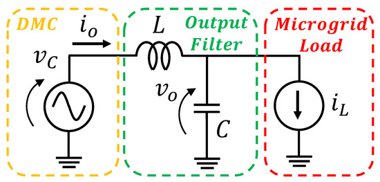
Figure 3.
System’s model equivalent circuit.
5. Model Predictive Current Control
The predictive current model is obtained, through a discretization of (1), using the Euler method with sampling period . In other words, the Euler method is a numerical integration technique that transforms the generic differential equation represented in (3) into its discrete form represented in (4).
The Euler method is used to transform the continuous differential Equation (1) into its discrete form as follows:
Thus, the predictive current model is obtained simply by rearranging (5) as follows:
In a DC microgrid, only one current is predicted as follows:
The variables (for ), which are the voltages synthesized by the DMCs, are the control actuation variables responsible for executing the predictive control. In other words, in each sampling step, the control predicts N (the number of possible switching states) different values of output currents (, , , or , depending on the topology) to be compared to the given current reference. The predicted currents are a function of the converter voltages () that are calculated N times for each possible switching state using (11)–(15). Each of the matrix equations described in (11)–(15) is used depending on the DMC topology utilized (see Figure 1). In Figure 2, which illustrates the control diagrams of each of the DMC topologies, one can observe the number of the matrix equation used in each case (see the predictive model blocks).
To sum up, the predictive control operates by predicting what would be the behavior of the output current in the next sampling step if a given voltage were synthesized by the converter. However, the possible instantaneous voltages that could be synthesized by the converter are limited by the possible switching states. In other words, the voltages synthesized by the converter () are a function of the converter’s switching state and the converter’s input voltage (see (11)–(15)). Therefore, if for instance, the microgrid topology shown in Figure 1a were to be used, the control diagram shown in Figure 2a would be utilized. In this case, (11) would be required. Then, at a given time step (k), the converter’s input voltages would be measured (, and ) and, by applying the N different possible switching states into (11) (27 possible switching states in this case as previously mentioned), N different values of converter voltages ( and ) would be obtained. By substituting the N different values of converter voltages into (7)–(9), N different values of output currents (, and ) would be obtained. By comparing the N different values of output currents calculated (, and ) with the current reference provided by the outer control loop, the predictive control is able to decide which switching state will be applied to the DMC switches in order to obtain, in the next time step, the output current desired.
The cost function is the part of the predictive control responsible for indicating the best switching state to trigger the DMC. The best switching state is the one that results in a predicted current with the lowest error in relation to the current reference. In the AC microgrid cases, the cost function used is the one shown in (16) and in the DC microgrid cases is the one shown in (17). By analyzing (16) and (17), it is clear that the best switching state, the one used to trigger the DMC’s switches in the next time step, is the one corresponding to the lowest value of .
6. Controller Parameters’ Design
By applying the Laplace transform in (2) and after some algebraic manipulation, the following equation is obtained:
In order to execute the control design regarding the reference tracking functionality using the linear-control tools, a linear model must be obtained. The MPC is a high-bandwidth controller [24,25] that can be modeled as a unitary gain when the voltage-controller dynamics are analyzed, since the latter has a closed-loop bandwidth much lower than the current-control one. Thus, using this approximation along with (18), the system’s linear model, used for the voltage-controller parameters’ design, can be obtained as shown in Figure 4.
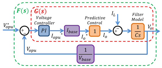
Figure 4.
Reference-tracking linear model.
This model can be used for designing the linear-voltage controllers for both the AC and DC microgrid cases. It can be used to represent DC signals (in the DC-microgrid case) or to represent the behavior of a single phase of a three-phase system (in the AC-microgrid case).
It is very desirable to analyze how a given disturbance affects the microgrid output voltage . Thus, the block diagram depicted in Figure 4 can be adapted to analyze the disturbance rejection characteristic of the system , resulting in Figure 5.
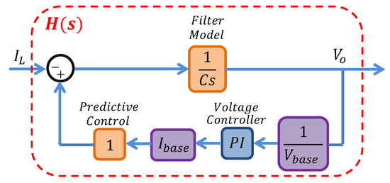
Figure 5.
Disturbance-rejection linear model.
7. Stability Analysis
In this section, the linear models shown in in Figure 4 and Figure 5 are implemented in Simulink/MATLAB in order to analyze the time and frequency domain characteristics of the closed-loop systems, for four different sets of parameters of the linear-voltage controller (, , , and ). These sets of parameters are shown in Table 1. The following gains were applied to the linear models: , which corresponds to the capacitance of the output filter (0.1 mF); , which is the output-voltage reference (phase-to-ground peak value of the output voltage corresponding to a 220-V line-to-line rms value); A), which corresponds to the output-current-rated value.

Table 1.
Voltage controllers’ parameters.
The software Simulink/MATLAB provides linear-control tools that allow one to interactively visualize the time domain and frequency domain characteristics of a given closed-loop system as a function of the proportional and integral gains of a PI controller. Thus, the authors visually selected the four different sets of parameters shown in Table 1, in such a way as to obtain different reference-tracking and disturbance-rejection dynamic behaviors, in order to validate the proposed linear model, as will be deeply analyzed and discussed both in this section and in Section 8. The validation was executed by comparing the output-voltage behavior obtained with the linear models, analyzed in this section, with the output-voltage behavior obtained with the real systems simulated in PSCAD/EMTDC, whose results are presented in Section 8.
By applying the four different sets of parameters to the block diagrams shown in Figure 4 and Figure 5, four different reference-tracking open-loop transfer functions (), four different reference-tracking closed-loop transfer functions (), and four different disturbance-rejection closed-loop transfer functions were obtained (), for , and 4.
In this article, the DMC control had two main objectives: the reference tracking functionality (to follow a voltage reference in order to keep the microgrid output voltage regulated) and the even more important objective of being able to reject load disturbances. The reference tracking dynamics were secondary, since the voltage reference was a constant signal, and once the system reached its operational voltage, not much control effort must be applied for this functionality. The disturbance rejection, on the other hand, was very important since the microgrid load and generation were constantly changing.
In Figure 6, the system’s responses to an unit-step signal are shown for the four different transfer functions previously described. Then, if one uses the set of parameters corresponding to the controller , they will obtain a highly damped system as shown in Figure 6 and as confirmed by its corresponding Bode plot shown in Figure 7 , which has a high phase margin equal to . However, this controller leads to a poor disturbance rejection characteristic since it presented considerably low negative magnitudes for low frequencies, as illustrated in Figure 8 , and noticing that the fundamental component was a DC signal (0 Hz) in the -rotating reference frame, in which the control was executed.
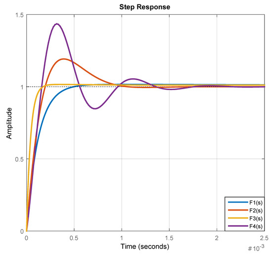
Figure 6.
Step response of the reference-tracking closed-loop transfer function.
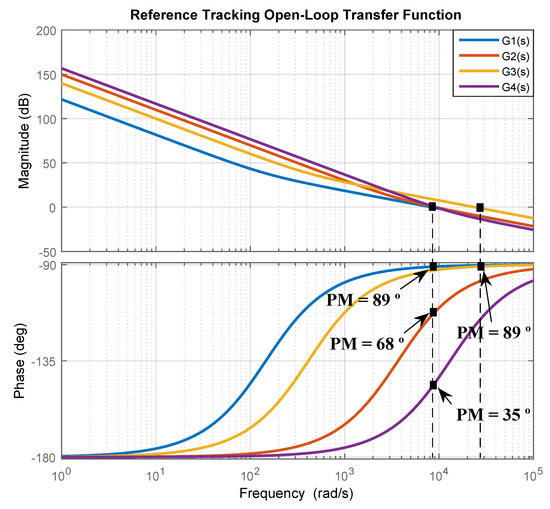
Figure 7.
Bode plot of the reference-tracking open-loop transfer function.
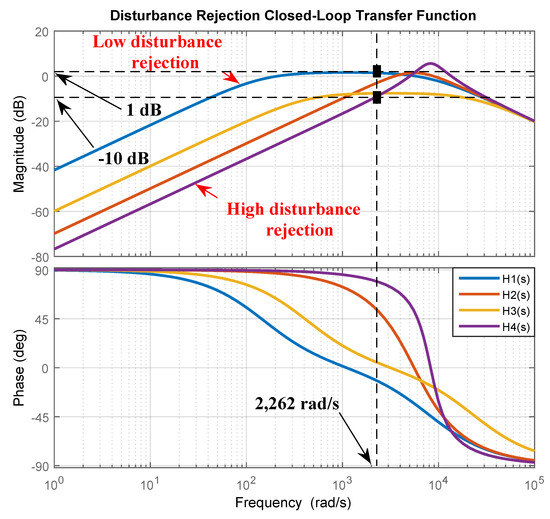
Figure 8.
Bode plot of the disturbance rejection closed-loop transfer function.
In order to improve the system disturbance rejection characteristic, one can increase its bandwidth using the controller , for example. By analyzing Figure 9, one can see that had higher bandwidth (24,341 rad/s) in comparison to (8,439 rad/s). This bandwidth increase was reflected in the faster time response, as illustrated in Figure 6. The usage of still resulted in a highly-damped dynamic response, with the phase margin equal to , as shown in Figure 7 . There was a limit to which the system bandwidth could be increased related to the limitations of the digital implementation of the control.
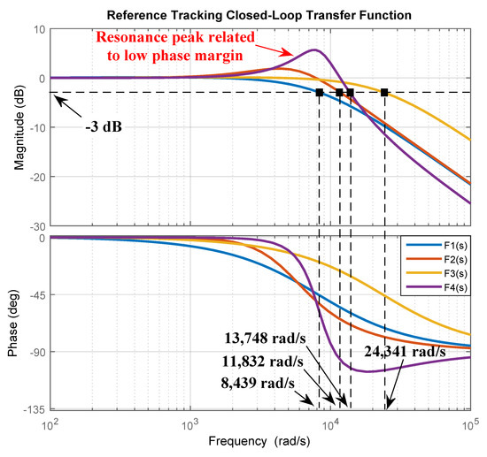
Figure 9.
Bode plot of the reference-tracking closed-loop transfer function.
Another solution to increase the system’s disturbance rejection characteristic was to decrease its phase margin, leading to a less damped dynamic response. and had poorly-damped responses (see Figure 6), related to their low phase margins ( and , respectively). However, the usage of and resulted in high disturbance rejection characteristics, as depicted in Figure 8 and , respectively), since they presented higher negative amplitudes (meaning smaller gains and higher attenuation), and thus, the output voltage suffered smaller variations for a given input load current . By analyzing Figure 9, one can notice that for the transfer function , a resonance peak appeared, which indicated the poorly-damped characteristic.
8. Simulation Results
In this section, simulation results are presented for each of the DMC topologies illustrated in Figure 1. These simulations were carried out on PSCAD/EMTDC, with all the devices shown in Figure 1 represented. The predictive control was executed through a C code, using the software compiler. The DMCs’ bidirectional switches were composed of IGBTs, and the microgrids were connected to a grid with voltage equal to 4 kV (phase-to-ground, peak value). This voltage was selected in such a way that the highest instantaneous voltage that the IGBTs must be capable of withstanding was equal to 6 kV, which corresponded to the voltage between two phases at a given instant in which one of them was in its peak. This is a voltage level compatible with modern IGBTs available in the industry. In every microgrid topology analyzed, the LC output filters presented equal parameters: mH and mF. The DMCs’ input filters were disregarded since the focus of this work was to analyze the operation of the microgrids and not the effect of such systems in their connection to the main grid.
8.1. AC-AC 3 × 3 DMC
In Figure 10, one can analyze the operation of the AC-AC 3 × 3 DMC (see Figure 1a) using the voltage controller .
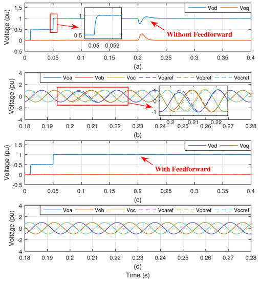
Figure 10.
AC-AC 3 × 3 DMC operation with . (a) Output voltage in the reference frame without feedforward, (b) output voltage without feedforward, (c) output voltage in the reference frame with feedforward, and (d) output voltage with feedforward.
In Figure 10a, one can notice that the system behaved according to what was analyzed in Figure 6, when the output-voltage reference changed from 0.5 pu to 1 pu, in which the voltage base was equal to 220 V (line-to-line rms value). In other words, the system was able to track the voltage reference properly with a smooth and damped dynamic behavior (see the signal). At s, a load step was imposed on the AC microgrid (connection of an RL load with mH and ), and the output voltage suffered a sag of about 25% when no feedforward was used, as shown in Figure 10a and as confirmed by the variation of the output-voltage signals in the reference frame , depicted in Figure 10b. When the feedforward term was added to the control, the signal remained constant (see Figure 10c), without oscillations, when the same load step was imposed at s. This showed the high disturbance rejection characteristic obtained using the feedforward term. This fact is further illustrated in Figure 10d, in which the output-voltage signals in the reference frame are shown. These signals did not oscillate and did not deviate from their corresponding references when the load step occurred.
In Figure 11, one can analyze the operation of the AC-AC 3 × 3 DMC using the voltage controller .
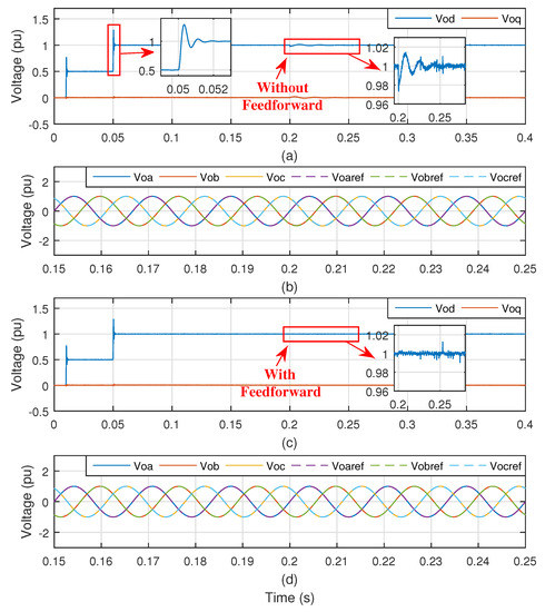
Figure 11.
AC-AC 3 × 3 DMC operation with . (a) Output voltage in the reference frame without feedforward, (b) output voltage without feedforward, (c) output voltage in the reference frame with feedforward, and (d) output voltage with feedforward.
By analyzing Figure 11a, it is possible to notice that the system had a reference-tracking dynamic behavior according to that expected from Figure 6, in which the system responded in a poorly-damped fashion to the step input signal. However, one can notice the high disturbance rejection characteristic obtained with this controller (as expected from Figure 8). Even without the feedforward term, the signal was barely affected (in comparison to Figure 10a) by the load connection that occurred at s. Of course, with the feedforward term (see Figure 11c), the disturbance rejection characteristic improved even further.
The selection of the voltage controller might be a good choice for this application, since the disturbance rejection functionality was more important than the reference tracking one. However, it is important to emphasize that the aim of this analysis was not to propose an ideal controller; it was rather to show some different tuning possibilities for the voltage controllers, depending on the specific requirements.
At s, the non-linear load was connected to the AC microgrid as one can observe in Figure 12a, in which the microgrid current is shown. The non-linear load corresponded to a three-phase diode-based rectifier supplying power to a resistive load with a value equal to . In this figure, the system operated using the voltage controller and no feedforward.
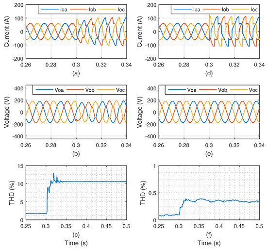
Figure 12.
AC-AC 3 × 3 DMC operating with and no feedforward. (a) Output current, (b) output voltage, and (c) Total Harmonic Distortion (THD) of the output voltage. AC-AC 3 × 3 DMC operating with and no feedforward. (d) Output current, (e) output voltage, and (f) THD of the output voltage.
By analyzing Figure 12b, it is possible to realize that the output voltage became considerably distorted due to the circulation of the harmonic currents, drawn by the non-linear load. This voltage profile presented a Total Harmonic Distortion (THD) of over 10% (see Figure 12c).
In order to understand the voltage distortion, one must consider Figure 8 and observe the gains of (1 dB) and of (−10 dB) at 2262 rad/s. Since the control was executed in the rotating reference frame with the synchronous angular speed , both the negative sequence fifth and the positive sequence seventh harmonics became a sixth harmonic in the rotating reference frame. In other words, 2262 rad/s and 2262 rad/s. The positive gain (1 dB) for meant that not only this transfer function did not attenuate the harmonic components, but it even provided a small increase for those frequencies. The non-linear load connection represented a model disturbance with different frequencies in comparison to the fundamental one. Thus, the analysis of this disturbance can be made through the Bode diagram represented in Figure 8. The connection of a non-linear load (represented by in the model) will distort more or less the output voltage (represented by in the model), depending on the magnitudes of the transfer functions represented in Figure 8. The transfer function , on the other hand, had a −10-dB gain that resulted in the filtering of those harmonic components, resulting in the voltage profile depicted in Figure 12e, which had a THD of less than 0.5%, as shown in Figure 12f.
One can notice that the DMC with MPC was able to synthesize a high power quality output voltage (see Figure 13a) even when the DMC input voltage (see Figure 13b) was distorted and unbalanced. This meant that a microgrid using this combination of converter and control could, for example, be connected to a “weak” grid situated in remote locations with the presence of distributed generation and non-linear loads and still provide a high power quality voltage to sensitive loads. In this simulation, the input voltage presented of the fifth harmonic component, of the seventh harmonic component, and of voltage sag in phase A.
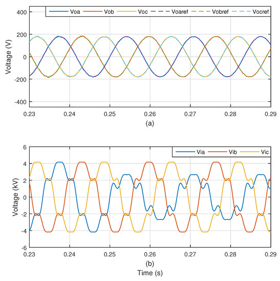
Figure 13.
AC-AC 3 × 3 DMC operation. (a) Output voltage and (b) distorted and unbalanced input voltage.
In Figure 14, it is possible to observe the operation of the AC microgrid when a power flow reversion occurred (see Figure 14c). That is to say, at s, both the linear and non-linear loads were disconnected, and the generator was connected to the microgrid as it started to provide power to the main grid. This was a 15-kW permanent-magnet synchronous generator. By analyzing Figure 14a, it is clear that the output voltage was not affected at all by this severe disturbance, illustrating the high disturbance rejection characteristic obtained.
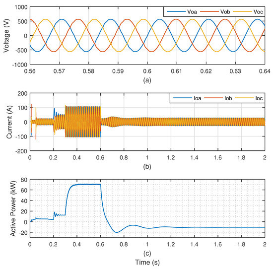
Figure 14.
AC microgrid during power flow reversion. (a) Output voltage, (b) output current, and (c) active power.
8.2. AC-DC 3 × 2 DMC
In Figure 15, one can analyze the operation of the AC-DC 3 × 2 DMC supplying power to a DC microgrid using the controller .
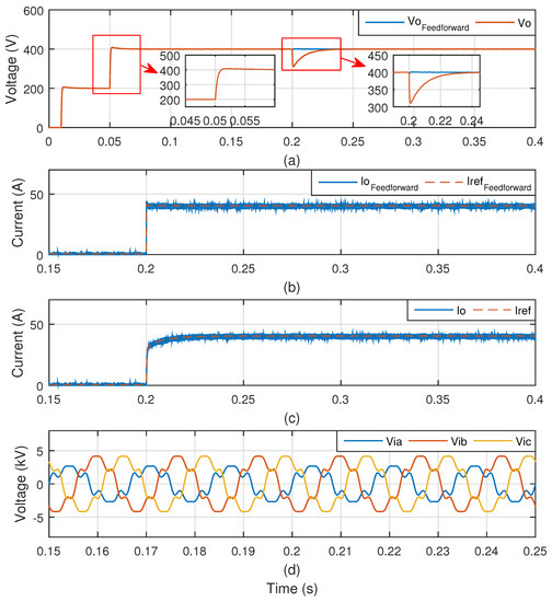
Figure 15.
AC-DC 3 × 2 DMC operation with . (a) Output voltage with and without feedforward, (b) output current with feedforward, (c) output current without feedforward, and (d) distorted and unbalanced input voltage.
As previously mentioned, the linear model presented in this work, and shown in Figure 4, can be used for designing the voltage controllers in both cases: AC and DC microgrids. Thus, the results depicted in Figure 15 were obtained using the controller previously presented. In Figure 15a, one can observe the DC microgrid output voltage in two different cases: with and without the feedforward term. At s, the voltage reference changed from 200 V to 400 V, and it was clear that the output voltage reached its steady-state point with a smooth and damped dynamic behavior, similar to the behavior obtained in Figure 10a, which corresponds to the AC microgrid operating using the same controller. Moreover, one can observe the high disturbance rejection characteristic obtained with the feedforward term when responding to a 16-kW load connection that occurred at s. In Figure 15b,c, it is possible to see the output currents for the cases with feedforward and without feedforward, respectively. Finally, in Figure 15d, one can observe the DMC input voltage , which was distorted and unbalanced, and the converter was able to synthesize a high power quality voltage despite the low power quality grid voltage.
In Figure 16, one can analyze the operation of the AC-DC 3 × 2 DMC supplying power to a DC microgrid using the controller . Once again, it is possible to notice that the dynamic behavior of the DC-microgrid voltage (see Figure 16a) was similar to the one obtained in the AC microgrid (see Figure 11a) regarding the reference-tracking functionality. In other words, in both cases, the output voltage followed the reference with poorly-damped dynamics when the controller was used. Besides, the disturbance-rejection characteristic was improved with when responding to the load connection that occurred at s (the voltage sag was smaller in Figure 16a than in Figure 15a when no feedforward was used), which also occurred in the AC microgrid using the same controller. In Figure 16b,c, one can observe the output current along with its reference for the cases with and without the feedforward term, respectively. These results proved the effectiveness of the MPC, which was able to track the reference quickly. Finally, Figure 16d shows the DMC input voltage , which was distorted and unbalanced.
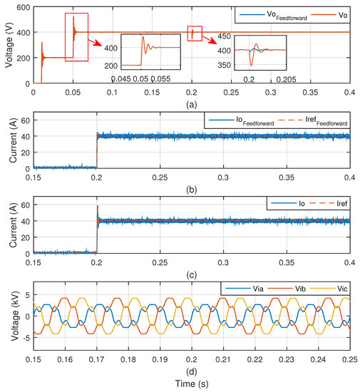
Figure 16.
AC-DC 3 × 2 DMC operation with . (a) Output voltage with and without feedforward, (b) output current with feedforward, (c) output current without feedforward, and (d) distorted and unbalanced input voltage.
8.3. AC-AC 2 × 3 DMC
In Figure 17, one can analyze the operation of the AC-AC 2 × 3 DMC supplying power to an AC microgrid, using and using the feedforward term, with the grid voltage balanced and sinusoidal. These results proved that it was possible to synthesize a three-phase output voltage properly using only two phases of the input voltage. In Figure 17a, it is possible to observe the DMC switched voltage , which was the output voltage measured before the filter, along with the converter’s input voltage . One can notice that the output voltage only switched between two phases of the three-phase input voltage, as expected from this topology. This fact led to a reduction of the output voltage power quality, as can be seen by carefully analyzing its waveform (see Figure 17b) and by observing its corresponding THD (see Figure 17c) with a value of approximately 1%, which is still a considerably low value. This voltage profile led to the output currents depicted in Figure 17d. It is important to notice that at s, the non-linear load was connected and the DMC was still able to synthesize an adequate output voltage with a THD with a value equal to approximately 1%.
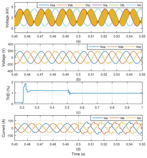
Figure 17.
AC-AC 2 × 3 DMC operation with the grid voltage balanced and sinusoidal. (a) Output switched voltage along with input voltage, (b) output voltage, (c) output voltage THD, and (d) output current.
In Figure 18, one can analyze the operation of the AC-AC 2 × 3 DMC supplying power to an AC microgrid, using and using the feedforward term, with the grid voltage unbalanced and distorted. In Figure 18a, it is possible to observe the switched voltage , which switched between two phases of the input voltage , including the sagged phase A. Still, the DMC was able to synthesize a proper three-phase-output voltage , as shown in Figure 18b, with a THD lower than 5%, even when the non-linear load was connected at s.
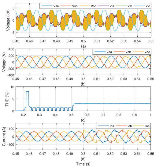
Figure 18.
AC-AC 2 × 3 DMC operation. (a) Output switched voltage along with input voltage, (b) output voltage, (c) output voltage THD, and (d) output current.
8.4. AC-DC 2 × 2 DMC
In Figure 19, one can observe the AC-DC 2 × 2 DMC synthesizing a DC voltage using only two phases of the input voltage. In Figure 19a, it is possible to see the switched output voltage switching between zero and the input line-to-line voltage , generating the DC voltage shown in Figure 19b, which only suffered a small sag, of approximately 0.5%, caused by the connection of a 16-kW load, leading to the current depicted in Figure 19c. The small sag was only possible because of the feedforward term used in the control.
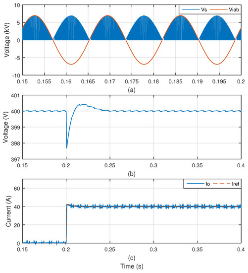
Figure 19.
AC-DC 2 × 2 DMC operation. (a) Output switched voltage along with input voltage, (b) output voltage, and (c) output current.
8.5. Hybrid DMC
In Figure 20, the results of the operation of the hybrid DMC (see Figure 1e) in the transition moments, from normal operation mode to islanded operation mode and from islanded operation mode back to normal operation mode, are shown. In Figure 20a, the SOC of the battery system is shown during the entire simulation period. At s, the AC loads were connected, and at s, the system was islanded. In order to emulate an islanding detection system, the grid contactors and opened at s, and at s, the DC-AC 2 × 3 DMC assumed the regulation of the AC-microgrid voltage. When the system became islanded, the SOC started to decrease as the battery was feeding the power required by the AC loads, which must be kept supplied.
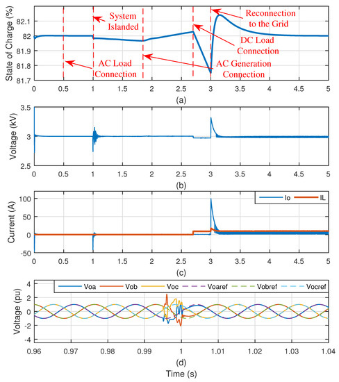
Figure 20.
Hybrid DMC operation. (a) Battery SOC, (b) DC output voltage, (c) DC output current, and (d) AC output voltage.
At s, the AC generator was connected and started to generate an amount of power higher than that required by the AC loads, in such a way that the battery SOC began to increase. At s, a large DC load was connected, so that the SOC started to decrease with a higher rate. At s, the system was connected back to the grid and the AC-DC 3 × 2 DMC returned to its function of regulating the battery SOC at the nominal operational value equal to 82%.
The DC voltage was kept constant, but it suffered an overshoot when the main grid was reconnected to the system (see Figure 20b), because the SOC control was designed to be fast (to fit in the simulation period), and thus, a current peak flowed to the battery (see Figure 20c) in order to recover its nominal value of SOC.
Moreover, by analyzing Figure 20d, one can observe the AC microgrid output voltage when the system became islanded. This voltage slightly deviated from its reference, but the system was able to quickly go back to properly tracking the reference, as the AC microgrid voltage regulation responsibility migrated from the AC-AC 3 × 3 DMC to the DC-AC 2 × 3 DMC.
9. Conclusions
In this paper, different DMC topologies were employed in a new application of power interface of microgrids. Some of the topologies were new and have the potential of reducing costs, increasing the efficiency and reliability of the systems, due to the reduced number of switches, which is very desirable in microgrid applications. The combination of linear control and MPC proved to be a robust control solution that was able to maintain a high power quality output voltage, despite the generation and loads connected to the microgrid. Besides, the analyzed systems were able to feed power with high power quality to a microgrid despite the voltage profile of the main grid to which it was connected. Thus, these systems were very suited to feed critical loads located in remote regions, connected to “weak” grids with the presence of distributed generation, for example. In Section 8, simulation results demonstrated that the microgrids’ output voltages were very robust to power variations that occurred due to load connection and generation fluctuations. In other words, the combination of DMC with MPC, along with an outer voltage control with a feedforward term, proved to be effective at rejecting disturbances, maintaining the output voltage with a high power quality. Besides, the DMC with MPC could synthesize a proper output voltage despite the input-voltage profile that contained a considerable amount of harmonic distortion and unbalance. The authors proposed a modeling that was suited to represent both AC and DC microgrid topologies when composed of a DMC operating with MPC. The proposed modeling proved to be suitable to design the parameters of the linear voltage controller that composed the outer control loop. A stability analysis was executed showing stability margins, bandwidths, and disturbance-rejection characteristics in a comparison between four different parameters of the voltage controller. The behavior predicted by the stability analysis, using the proposed linear model, matched the actual behavior of the real systems simulated on PSCAD/EMTDC, as the systems behaved satisfactorily with proper dynamics and proper disturbance rejection behavior, validating the linear model.
Simulation results demonstrated that the DMC topologies with a reduced number of switches were capable of properly synthesizing the microgrids’ output voltages, even though some reduction on the output-voltage power quality was noticed. The DMC topologies with a reduced number of switches utilized only two phases of the three-phase-input voltage in order to synthesize either an AC-microgrid three-phase voltage or a DC-microgrid voltage. The authors introduced the hybrid DMC that offered the possibility of islanded operation by integrating the DC microgrid and its battery with the AC microgrid, maintaining a constant power supply to the loads. Simulation results demonstrated that the hybrid DMC was able to maintain a proper AC microgrid output voltage in the transitions from grid-connected mode to islanded mode and back to grid-connected mode. In other words, the AC microgrid output voltage retained a high power quality when the responsibility of synthesizing it migrated from the AC-AC 3 × 3 DMC (with the main grid voltage as an input) to the DC-AC 2 × 3 DMC (with the DC-microgrid-battery voltage as an input) and vice versa. Finally, the authors proposed the reduced hybrid DMC that operated similarly to the hybrid DMC, but with a reduced number of switches, resulting in a solution with possibly low cost, high reliability, high efficiency, low failure rate, and high lifespan. As future works, the authors intend to execute analysis regarding the effect of the connection of the proposed topologies to the main grid. In other words, besides issues related to harmonic distortion caused by the typical harmonic currents reflected to the main grid by the DMC, other serious issues might occur. For example, the connection of the topologies with a reduced number of switches to the main grid might be harmful since these converters are connected to only two phases of the grid. In order to execute this analysis, a deeper modeling of the grid to which the system is connected will be required. In the present work, the grid was modeled as a voltage source.
Author Contributions
G.G. established the major part of this paper, which included conceptualization, formal analysis, investigation, modeling, and simulation, and was responsible for writing the original draft preparation. M.S. contributed with conceptualization and text review. T.T. contributed with formal analysis and text review. R.D. contributed with conceptualization and text review. M.A. provided resources, helped with funding acquisition, and provided supervision. J.G. provided supervision and text review.
Funding
This research was funded by the National Council for Scientific and Technological Development (CNPq).
Conflicts of Interest
The authors declare no conflict of interest.
References
- Parhizi, S.; Lotfi, H.; Khodaei, A.; Bahramirad, S. State of the art in research on microgrids: A review. IEEE Access 2015, 3, 890–925. [Google Scholar] [CrossRef]
- Wang, X.; Guerrero, J.M.; Blaabjerg, F.; Chen, Z. A Review of Power Electronics Based Microgrids. J. Power Electron. 2012, 12, 181–192. [Google Scholar] [CrossRef]
- Guerrero, J.M.; Chandorkar, M.; Lee, T.L.; Loh, P.C. Advanced Control Architectures for Intelligent Microgrids Part I: Decentralized and Hierarchical Control. IEEE Trans. Ind. Electron. 2013, 60, 1254–1262. [Google Scholar] [CrossRef]
- Guerrero, J.M.; Loh, P.C.; Lee, T.L.; Chandorkar, M. Advanced Control Architectures for Intelligent Microgrids Part II: Power Quality, Energy Storage, and AC/DC Microgrids. IEEE Trans. Ind. Electron. 2013, 60, 1263–1270. [Google Scholar] [CrossRef]
- Dragicevic, T.; Lu, X.; Vasquez, J.C.; Guerrero, J.M. DC Microgrids Part I: A Review of Control Strategies and Stabilization Techniques. IEEE Trans. Power Electron. 2016, 31, 4876–4891. [Google Scholar] [CrossRef]
- Dragicevic, T.; Lu, X.; Vasquez, J.; Guerrero, J.M. DC Microgrids Part II: A Review of Power Architectures, Applications, and Standardization Issues. IEEE Trans. Power Electron. 2016, 31, 3528–3549. [Google Scholar] [CrossRef]
- Che, L.; Shahidehpour, M. DC Microgrids: Economic Operation and Enhancement of Resilience by Hierarchical Control. IEEE Trans. Smart Grid 2014, 5, 2517–2526. [Google Scholar]
- Saeedifard, M.; Graovac, M.; Dias, R.F.; Iravani, R. DC Power Systems: Challenges and Opportunities. In Proceedings of the IEEE PES General Meeting, Providence, RI, USA, 25–29 July 2010; pp. 1–7. [Google Scholar]
- Liu, X.; Wang, P.; Loh, P.C. A Hybrid AC/DC Microgrid and Its Coordination Control. IEEE Trans. Smart Grid 2011, 2, 278–286. [Google Scholar]
- Syed, M.H.; Zeineldin, H.H.; El Moursi, M.S. Hybrid micro-grid operation characterisation based on stability and adherence to grid codes. IET Gener. Transm. Distrib. 2014, 21, 563–572. [Google Scholar] [CrossRef]
- Majumder, R. A Hybrid Microgrid With DC Connection at Back to Back Converters. IEEE Trans. Smart Grid 2014, 5, 251–259. [Google Scholar] [CrossRef]
- De Bosio, F.; Luna, A.C.; Ribeiro, L.A.S.; Graells, M.; Saavedra, O.R.; Guerrero, J.M. Analysis and improvement of the energy management of an isolated microgrid in Lencois island based on a linear optimization approach. In Proceedings of the ECCE 2016—IEEE Energy Conversion Congress and Exposition, Milwaukee, WI, USA, 18–22 September 2016. [Google Scholar] [CrossRef]
- Neto, P.B.L.; Saavedra, O.R.; De Souza Ribeiro, L.A. A Dual-Battery Storage Bank Configuration for Isolated Microgrids Based on Renewable Sources. IEEE Trans. Sustain. Energy 2018, 9, 1618–1626. [Google Scholar] [CrossRef]
- Ribeiro, L.A.D.S.; Freijedo, F.D.; de Bosio, F.; Lima, M.S.; Guerrero, J.M.; Pastorelli, M. Full Discrete Modeling, Controller Design and Sensitivity Analysis for High Performance Grid-Forming Converters in Islanded Microgrids. IEEE Trans. Ind. Appl. 2018, 54, 6267–6278. [Google Scholar] [CrossRef]
- Liu, W.; Tarasiuk, T.; Gorniak, M.; Guerrero, J.M.; Savaghebi, M.; Vasquez, J.C.; Su, C.L. Power quality assessment in real shipboard microgrid systems under unbalanced and harmonic AC bus voltage. In Proceedings of the Conference Proceedings—IEEE Applied Power Electronics Conference and Exposition—APEC, San Antonio, TX, USA, 4–8 March 2018; pp. 521–527. [Google Scholar] [CrossRef]
- Guerrero, J.M.; Jin, Z.; Liu, W.; Othman, M.B.; Savaghebi, M.; Anvari-Moghaddam, A.; Meng, L.; Vasquez, J.C. Shipboard Microgrids: Maritime Islanded Power Systems Technologies. In Proceedings of the PCIM Asia 2016, International Exhibition and Conference for Power Electronics, Intelligent Motion, Renewable Energy and Energy Management, Shanghai, China, 28–30 June 2016; pp. 1–8. [Google Scholar] [CrossRef]
- Wheeler, P.; Rodriguez, J.; Clare, J.C.; Empringham, L.; Weinstein, A. Matrix Converters: A Technology Review. IEEE Trans. Ind. Electron. 2002, 49, 276–288. [Google Scholar] [CrossRef]
- Rodriguez, J.; Rivera, M.; Kolar, J.W.; Wheeler, P.W. A Review of Control and Modulation Methods for Matrix Converters. IEEE Trans. Ind. Electron. 2012, 59, 58–70. [Google Scholar] [CrossRef]
- Empringham, L.; Kolar, J.W.; Rodriguez, J.; Wheeler, P.W.; Clare, J.C. Technological issues and industrial application of matrix converters: A review. IEEE Trans. Ind. Electron. 2013, 60, 4260–4271. [Google Scholar] [CrossRef]
- Aten, M.; Towers, G.; Whitley, C.; Wheeler, P.; Clare, J.; Bradley, K. Reliability comparison of matrix and other converter topologies. IEEE Trans. Aerosp. Electron. Syst. 2006, 42, 867–873. [Google Scholar] [CrossRef]
- Friedli, T.; Kolar, J.W. Comprehensive Comparison of Three-Phase AC-AC Matrix Converter and Voltage DC-Link Back-to-Back Converter Systems. In Proceedings of the 2010 International Power Electronics Conference (IPEC), Sapporo, Japan, 21–24 June 2010; pp. 2789–2798. [Google Scholar] [CrossRef]
- Kolar, J.; Baumann, M.; Schafmeister, F.; Ertl, H. Novel three-phase AC-DC-AC sparse matrix converter. In Proceedings of the APEC. Seventeenth Annual IEEE Applied Power Electronics Conference and Exposition, Dallas, TX, USA, 10–14 March 2002; Volume 2, pp. 777–791. [Google Scholar]
- Kolar, J.W.; Schafmeister, F.; Round, S.D.; Ertl, H. Novel three-Phase AC-AC sparse matrix converters. IEEE Trans. Power Electron. 2007, 22, 1649–1661. [Google Scholar] [CrossRef]
- Vazquez, S.; Leon, J.; Franquelo, L.; Rodriguez, J.; Young, H.; Marquez, A.; Zanchetta, P. Model Predictive Control: A Review of Its Applications in Power Electronics. IEEE Ind. Electron. Mag. 2014, 8, 16–31. [Google Scholar] [CrossRef]
- Vazquez, S.; Rodriguez, J.; Rivera, M.; Franquelo, L.G.; Norambuena, M. Model Predictive Control for Power Converters and Drives: Advances and Trends. IEEE Trans. Ind. Electron. 2017, 64, 935–947. [Google Scholar] [CrossRef]
- Elizondo, J.L.; Olloqui, A.; Rivera, M.; Macias, M.E.; Probst, O.; Micheloud, O.M.; Rodriguez, J. Model-based predictive rotor current control for grid synchronization of a DFIG driven by an indirect matrix converter. IEEE J. Emerg. Sel. Top. Power Electron. 2014, 2, 715–726. [Google Scholar] [CrossRef]
- Chikha, S.; Barra, K.; Reama, A. Predictive current control of a wind energy conversion system based DFIG via direct matrix converter. In Proceedings of the 2015 6th International Renewable Energy Congress (IREC), Sousse, Tunisia, 24–26 March 2015. [Google Scholar] [CrossRef]
- Rivera, M.; Elizondo, J.L.; Macías, M.E.; Probst, O.M.; Micheloud, O.M.; Rodriguez, J.; Rojas, C.; Wilson, A. Model Predictive Control of a Doubly Fed Induction Generator with an Indirect Matrix Converter. In Proceedings of the 36th Annual Conference on IEEE Industrial Electronics Society, Glendale, AZ, USA, 7–10 November 2010; pp. 2959–2965. [Google Scholar]
- Gontijo, G.F.; Tricarico, T.C.; Franca, B.W.; da Silva, L.F.; van Emmerik, E.L.; Aredes, M. Robust Model Predictive Rotor Current Control of a DFIG Connected to a Distorted and Unbalanced Grid Driven by a Direct Matrix Converter. IEEE Trans. Sustain. Energy 2018, 10, 1380–1392. [Google Scholar] [CrossRef]
- Olloqui, A.; Elizondo, J.L.; Rivera, M.; Macias, M.E.; Micheloud, O.M.; Pena, R.; Wheeler, P. Indirect power control of a DFIG using model-based predictive rotor current control with an indirect matrix converter. In Proceedings of the IEEE International Conference on Industrial Technology, Seville, Spain, 17–19 March 2015; pp. 2275–2280. [Google Scholar] [CrossRef]
- Rizzoli, G.; Zarri, L.; Mengoni, M.; Tani, A.; Attilio, L.; Serra, G.; Casadei, D. Comparison between an AC-DC matrix converter and an interleaved DC-dc converter with power factor corrector for plug-in electric vehicles. In Proceedings of the IEEE International Electric Vehicle Conference, IEVC 2014, Florence, Italy, 17–19 December 2014. [Google Scholar] [CrossRef]
- Zhang, J.; Li, L.; Dorrell, D.G. Control and Applications of Direct Matrix Converters: A Review. Chin. J. Electr. Eng. 2018, 4, 18–27. [Google Scholar]
- Zhang, J.; Li, L.; He, T.; Aghdam, M.M.; Dorrell, D.G. Investigation of direct matrix converter working as a versatile converter (AC/AC, AC/DC, DC/AC, DC/DC conversion) with predictive control. In Proceedings of the IECON 2017—43rd Annual Conference of the IEEE Industrial Electronics Society, Beijing, China, 29 October–1 November 2017; pp. 4644–4649. [Google Scholar] [CrossRef]
- Dorrell, D.G. Understanding and modeling of matrix converters for application in renewable energy and micro grid applications. In Proceedings of the IECON Proceedings (Industrial Electronics Conference), Dallas, TX, USA, 29 October–1 November 2014; Volume 1, pp. 4409–4415. [Google Scholar] [CrossRef]
- Fang, F.; Li, Y.W. Modulation and control method for bidirectional isolated AC/DC matrix based converter in hybrid AC/DC microgrid. In Proceedings of the 2017 IEEE Energy Conversion Congress and Exposition, ECCE 2017, Cincinnati, OH, USA, 1–5 October 2017; pp. 37–43. [Google Scholar] [CrossRef]
- Zhang, J.; Li, L.; Malekjamshidi, Z.; Dorrell, D.G. Predictive voltage control of direct matrix converter with reduced number of sensors for the renewable energy and microgrid applications. In Proceedings of the 2017 IEEE Energy Conversion Congress and Exposition, ECCE 2017, Cincinnati, OH, USA, 1–5 October 2017; pp. 3309–3315. [Google Scholar] [CrossRef]
- Zhang, J.; Li, L.; Dorrell, D.G.; Norambuena, M.; Rodriguez, J. Predictive Voltage Control of Direct Matrix Converters with Improved Output Voltage for Renewable Distributed Generation. IEEE J. Emerg. Sel. Top. Power Electron. 2018, 6777, 296–308. [Google Scholar] [CrossRef]
- Aydogmus, O.; Sünter, S.; Boztas, G. Design of a novel single-phase in two-phase out matrix converter driving an induction motor. IET Power Electron. 2016, 9, 1391–1397. [Google Scholar] [CrossRef]
- Wu, H.; Ge, H.; Xu, Y.; Zhang, W. The power factor correction of three-phase to single-phase matrix converter with an active power decoupling capacity. In Proceedings of the IEEE Transportation Electrification Conference and Expo, ITEC Asia-Pacific 2014—Conference Proceedings, Beijing, China, 31 August–3 September 2014; pp. 1–5. [Google Scholar] [CrossRef]
- Mirazimi, M.; Sharifian, M.B.B.; Babaei, E. Hysteresis control of a three-phase to two-phase matrix converter. In Proceedings of the India International Conference on Power Electronics, IICPE, Delhi, India, 6–8 December 2012; pp. 1–5. [Google Scholar] [CrossRef]
- Saleh, M.; Iqbal, A.; Ahmed, S.M.; Abu Rub, H.; Kalam, A. Carrier based PWM technique for a three-to-six phase matrix converter for supplying six-phase two-motor drives. In Proceedings of the IECON Proceedings (Industrial Electronics Conference), Melbourne, Australia, 7–10 November 2011; pp. 3470–3475. [Google Scholar] [CrossRef]
- Kwak, S.; Kim, T.; Vodyakho, O. Space Vector Control Methods for Two-Leg and Three-Leg Based Direct AC to AC Converter for Two-Phase Drive Systems. In Proceedings of the 2008 34th Annual Conference of IEEE Industrial Electronics, Orlando, FL, USA, 10–13 November 2008; pp. 4–6. [Google Scholar]
- Akagi, H.; Watanabe, E.H.; Aredes, M. Instantaneous Power Theory and Applications to Power Conditioning; John Wiley & Sons: Hoboken, NJ, USA, 2007. [Google Scholar]
© 2019 by the authors. Licensee MDPI, Basel, Switzerland. This article is an open access article distributed under the terms and conditions of the Creative Commons Attribution (CC BY) license (http://creativecommons.org/licenses/by/4.0/).