Article

Analytical Study of Tri-Generation System Integrated with Thermal Management Using HT-PEMFC Stack

Eco-friendly Vehicle R & D Division, Korea Automotive Technology Institute, 303 Pungse-Ro, Pungse-Myeon, Cheonan-Si 330-912, Korea
*
Author to whom correspondence should be addressed.
Energies 2019, 12(16), 3145; https://doi.org/10.3390/en12163145
Submission received: 13 June 2019 / Revised: 5 August 2019 / Accepted: 7 August 2019 / Published: 9 August 2019
(This article belongs to the Special Issue Modelling and Simulation of Smart Energy Management Systems)

Abstract

:
Recently, extensive studies on power generation using clean energy have been conducted to reduce air pollution and global warming. In particular, as existing internal combustion engines lose favor to power generation through hydrogen fuel cells, the development of tri-generation technology using efficient and reliable fuel cells is gaining importance. This study proposes a tri-generation thermal management model that enables thermal control and waste heat utilization control of a high-temperature PEMFC stack that simultaneously satisfies combined cooling, heating, and power (CCHP) load. As the high-temperature PEMFC stack operates at 150 °C or more, a tri-generative system using such a stack requires a thermal management system that can maintain the operating temperature of the stack and utilize the stack waste heat. Thus, to apply the waste heat produced through the stack to heating (hot water) and absorption cooling, proper distribution control of the thermal management fluid (cooling fluid) of the stack is essential. For the thermal management fluid control design, system analysis modeling was performed to selectively design the heat exchange amount of each part utilizing the stack waste heat. In addition, a thermal management system based on thermal storage was constructed for complementary waste heat utilization and active stack cooling control. Through a coupled analysis of the stack thermal management model and the absorption cooling system model, this study compared changes in system performance by cooling cycle operation conditions. This study investigated into the appropriate operating conditions for cooling operation in a tri-generative system using a high-temperature PEMFC stack.

1. Introduction

With rising air pollution due to fossil fuel-based power generation, improving energy efficiency through environmentally friendly power generation technology has increasingly gained widespread attention. Currently, cooling, heating, and power use in buildings comprises approximately 40% of the world’s main energy consumption [1]. However, most of the energy used is generated from city-based centralized power stations with efficiency of less than 40%, resulting in high emissions of environmental pollutants and high operating costs [2]. Researchers have investigated various methods to address these issues, among which micro-generation technology has garnered attention for achieving fuel efficiency above 70% and system efficiency of up to 90% [3]. Micro-generation technology enables direct conversion to the required electric energy using the energy source from the application target. It is being introduced in hotels, airports, hospitals, and commercial buildings [4,5,6].
In addition to micro-generation technology, micro combined heat and power (CHP) and micro combined cooling, heating, and power (CCHP) systems have also emerged as environmentally friendly energy-saving systems [7]. Both systems provide power and thermal energy, which are mainly consumed for buildings or utilities. However, unlike CHP systems, CCHP systems provide cooling in addition to heating and power [8]. CCHP systems, also referred to as tri-generative systems, can be configured for various forms of energy consumption. Accordingly, researchers are actively investigating related systems. In engine power generation using gas and fossil fuels, power is generated by a secondary power source generated through a chemical reaction such as combustion. To alleviate the reduction of power production efficiency caused by this conversion process, researchers are investigating CCHP systems using a fuel cell that generates electricity through the chemical reaction of the primary fuel. In this regard, many studies on fuel cells in buildings are underway. De Lorenzo et al. used the simulation model of an intermediate temperature solid oxide fuel cells (IT-SOFC) system to evaluate the influence of key variables of the system performance with the supply of biogas and the amount of carbon generation [9]. Verhaert et al. has confirmed that it provides superior thermal performance and similar electrical performance at fixed load conditions as compared to PEMFC systems through analysis of Alkaline fuel cell (AFC)-based micro-CHP systems [10]. Kwan et al. introduced the Fuel cell and thermoelectric combined heat and power (FC-TEG-CHP) system and carried out research to improve the efficiency in terms of exergy through comparison of the FC-CHP system [11]. Mehrpooya et al. simulated the system to evaluate its suitability for SOFC-CCHP hybrid systems, including dual-effect absorption cooling cycles [12]. Ebrahimi and Derakhshan constructed PEMFC, thermoelectric and absorption chiller-based micro CCHP, and confirmed 39% fuel reduction performance compared to the conventional systems [13]. Cozzolino designed a low-temperature PEMFC-based CCHP system and studied the performance changes and optimum points according to the load of CHP and CCP. Based on this research, studies have sought to identify the optimum point of load fluctuation according to season regardless of whether an auxiliary system is integrated [14].
SOFC has the advantage of using solid electrolytes and non-noble metal catalysts. However, it operates at high temperatures of at least 700 °C, complicating the constituent system and using relatively expensive special alloys that can withstand high temperatures and high pressures [15]. A low-temperature PEMFC operates at low temperatures of less than 80 °C, resulting in low utilization energy levels, requiring a humidification device, CO removal device, and condensate treatment device, and suffer from flooding [16]. In contrast, high-temperature PEMFC fuel cells have an operating temperature above the boiling point of water (approximately 180 °C). Thanks to high operating temperatures, these systems can omit additional device such as humidifiers and secure CO tolerance, thereby increasing durability [17]. In contrast with low-temperature PEMFC systems, as all the water in a high-temperature PEMFC system exists in a vapor state, it can be used in a tri-generative system incorporating cooling and heating equipment using high-temperature waste heat recovery in a simplified water and reactive gas distribution system. This gives it high applicability in autothermal reforming systems. Based on these advantages, the development of optimization techniques for stack thermal management and waste heat recovery systems is urgently required to increase the performance and dissemination of CCHP systems incorporating high-temperature PEMFC [18,19,20,21,22].
In this study, we modeled the heating (hot water) and LiBr absorption cooling system using waste heat recovery in addition to thermal management of the 5 kW high-temperature PEMFC stack power applied to the tri-generative system. We then analyzed the system using the commercial program FloMaster. In the tri-generative system, as it was necessary to control the distribution of triehylene glycol (TEG), the thermal management fluid of the overall system, we conducted a system analysis to confirm the appropriate control range under the corresponding operating conditions. This was necessary to configure the complementary waste heat recovery amount by cooling and heating the load and managing the active thermal management of the stack, which operates at high temperatures of at least 150 °C based on thermal storage to manage the thermal management fluid. To approach this effectively, we implemented an integrated tri-generation thermal management system model that can be interfaced with FloMaster through the absorption cooling system configuration using the Engineering Equation Solver (EES) program. With this configuration, we compared stack thermal management and system performance changes according to the main operating conditions of the cooling system.

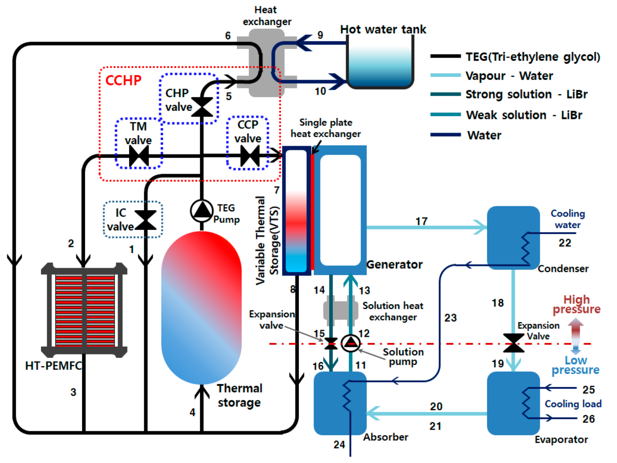
2. Tri-Generative System Description Based on HT-PEMFC System

Figure 1 shows a schematic diagram of the constructed tri-generative system including a high-temperature PEMFC thermal management system. TEG (the thermal management fluid of the overall tri-generative system) and the LiBr aqueous solution (the hydraulic fluid of the cooling system) are represented by the black and blue lines, respectively. For the CHP cycle, TEG was selected as the operating fluid in which phase change did not occur above 160 °C, which is the operating temperature of the high-temperature PEMFC. TEG is typically used as the cooling fluid from 100 to 280 °C or less. For the absorption cooling cycle, LiBr-Water was used as the refrigerant aqueous solution with the concentration maintained from 50 to 65%.
The operating components of the high-temperature PEMFC thermal management and tri-generation cycle consist of the high-temperature PEMFC stack, thermal storage, partial TEG control valves, TEG circulation pump, heat exchanger, and absorption cooling system. This system controls the flow of TEG from the thermal storage to realize tri-generation with high-temperature PEMFC thermal management. TEG from the thermal storage is transferred through a high-temperature TEG circulation pump; to regulate the entire CHP cycle flow, the TEG passes through position (1) through the internal circulation (IC) valve and returns to the thermal storage. Through the TM valve, the total TEG flow determined by the IC valve replenishes heat through high-temperature PEMFC cooling (positions (2), (3), and (4)). The necessary hot water is provided through the CHP valve (consideration of heating and stack cooling amount is possible) (positions (5), (6), and (4)), and the amount of heat required for absorption cooling (positions (7), (8) and (4)) via the CCP valve is provided to the variable heat exchanger and then returned to the thermal storage. By single plate heat exchange, the heat quantity transferred to the generator reduces the concentration of LiBr-Water to generate vapor, the refrigerant in the absorption cooling cycle. The steam thus generated enters the condenser through (17), is condensed by the cooling water, and then passes through the liquid phase (18). The states of position (18) and (19) are divided by the expansion valve and the solution pump into relatively high and low pressure states, and evaporation is then performed with the latent heat in the evaporator through throttling. The vaporization efficiency Qe can be obtained from the evaporated vapor. The vapor evaporated at low pressures is absorbed by the high-concentration LiBr aqueous solution in the lower portion of the absorber through position (20) and (21). The LiBr aqueous solution, which absorbs the refrigerant vapor, is transferred to the generator by the solution pump (positions (11), (12) and (13)), and the high-concentration LiBr aqueous solution remaining in the generator is transferred to the absorber by the height difference (positions (14), (15) and (16)).

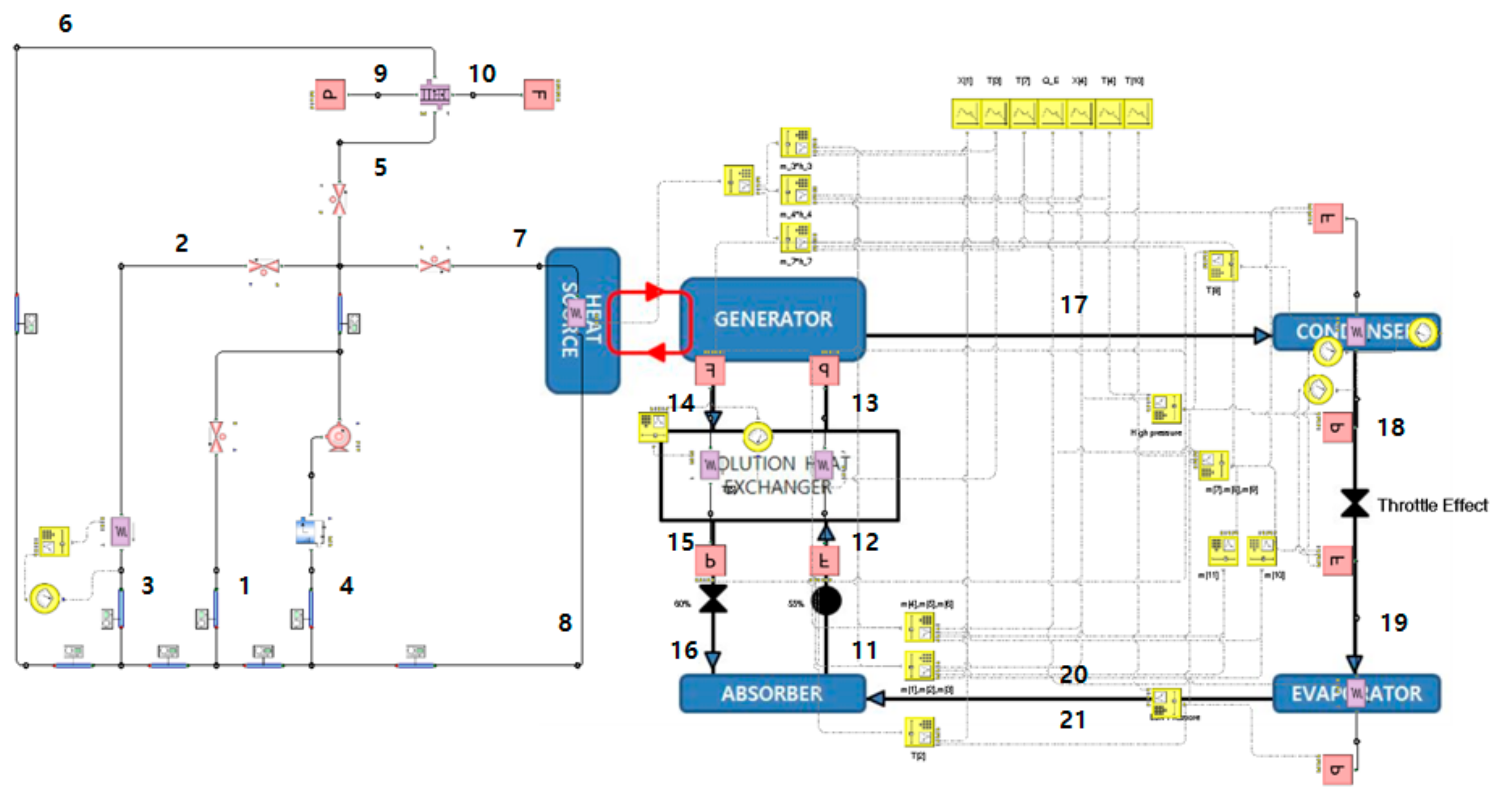
3. Tri-Generative System Modeling

3.1. Stack Thermal Management and CHP System Cycle

We made the following assumptions to model the generation and exhaust heat changes of the high-temperature PEMFC stack according to the operating temperature. The operating state of the cell is steady and one-dimensional. The temperature is evenly distributed over the electrodes in the stack, and the reactive gas mixture is an ideal gas fluid. In addition, the outlet temperature of the cathode is equal to the operating temperature of the stack. The heat loss due to ambient temperature is relatively low and therefore ignored. All the heating value of the stack is transferred to the cooling fluid. The parameters applied to the model are shown in Table 1.
The anode (1), cathode (2), and overall electrochemical reaction (3) of the high-temperature PEMFC are as follows:
H2 → 2H+ + 2e
1 2   O 2   +   2 H +   +   2 e     H 2 O
H 2   +   1 2   O 2     H 2 O
Vcell, the voltage of a single cell unit, is calculated through (4) using Vact (activation voltage loss), Vocv (open circuit voltage), and Vohmic (ohmic overvoltage).
Vcell = VocvVohmicVact
To calculate Vact and Vohmic, Rconc and Rohmic are obtained by using the temperature-only function through the linear regression method ((5) and (6)) [23].
R c o n c = 0.4306     8.203 × 10 4 T c e l l + 273.15
R o h m i c = 0.2289     1.667 × 10 4 T c e l l + 273.15
Vact, and Vohmic were calculated as shown in (7) and (8) through the calculated Rconc and Rohmic [24].
V a c t = R T c e l l + 273.15 α a F s i n h 1 I 2 k e h θ h 2 + R T c e l l + 273.15 4 α c F l n I + I 0 I 0 + R c o n c I λ a i r 1
V o h m i c = I · R o h m i c
where R is the ideal gas constant, Rconc is the concentration resistance, Rohmic is the ohmic resistance, Tcell is the operating temperature, αa is the anode charge transfer coefficient, F is the faraday constant, I is the current density, keh is the hydrogen elecro-oxidation rate constant, θh2 is the hydrogen surface coverage, αc is the cathode charge transfer coefficient, I0 is the exchange current density, and λair is the air stoichiometry.
The P s t a c k (total electric power) and P t h e r m a l (thermal power) of the stack can be calculated through (9) and (10) under the assumption that the individual stack performances are all the same.
P s t a c k = N · V c e l l · I · A c e l l
P t h e r m a l = N · H H V 2 F V c e l l · I · A c e l l
where Acell is the Single cell active area, HHV is the higher heating value of the ideal gas constant, Tcell is the operating temperature, and N is the number of cells in the stack [25].
We assume that the heat transferred to TEG, the coolant of the CHP cycle, is equal to the heat generated by the stack. All cycles were analyzed using the commercial program FloMaster based on the Energy (11), Mass (12), and Species conservation (13). In Equation (13), x is mass fraction.
m ˙ h i n + Q ˙ i n = m ˙ h o u t + Q ˙ o u t
m ˙ i n = m ˙ o u t
m ˙ x i n = m x ˙ o u t

3.2. LiBr-Water Absorption Refrigerator Cycle

The input values in Table 2 were used to observe basic performance. All flow control devices, such as control valves and flow pumps, are assumed to be adiabatic from the external. In addition, we assumed the same pressure for the evaporator and absorber, and the same pressure for the generator and condenser.
The cooling performance of the evaporator is defined by the energy balance equation:
Q e = m ˙ 20 h 20 + m ˙ 21 h 21 m ˙ 19 h 19
m ˙ 20 is the liquid mass flow rate, and m ˙ 21 is the vapor mass flow rate at the outlet of the evaporator. The ratio of m ˙ 20 to m ˙ 21 is fixed at 0.025. The mass flow rate of the evaporator is defined by the mass balance equation:
m ˙ 19 = m ˙ 20 + m ˙ 21
The pressure at the outlet of the evaporator P 20 and the enthalpy of the vapor state h 20 are calculated solely by the function of the outlet temperature of the evaporator. The enthalpy of a certain liquid phase h 21 is set as the enthalpy of the saturated liquid state at the same pressure through the pressure and enthalpy diagram of water [26]:
P = 2 × 10 12 T 6 3 × 10 9 T 5 + 2 × 10 7 T 4 + 3 × 10 5 T 3 + 1.4 × 10 3 T 2 + 4.44 × 10 2 T + 0.6108
h v = 1.2539 × 10 3 T 2 + 1.88060937 T + 2500.559
The enthalpy at the inlet end of the evaporator h 19 and the enthalpy at the outlet end of the condenser h 18 do not change through the throttling process; this is used to obtain h 19 . h 19 is the enthalpy of the saturated liquid state in high-side pressure; high-side pressure is calculated using generator solution outlet temperature T14 and LiBr strong solution mass fraction X14 as follows [27]:
A 0 = 2.00755 ,     A 1 = 0.16976 ,     A 2 = 0.003133362 ,     A 3 = 0.0000197668
B 0 = 124.937 ,     B 1 = 7.71649 ,     B 2 = 0.152286 ,     B 3 = 0.0007959
A = A 0 X 0 + A 1 X 1 + A 2 X 2 + A 3 X 3
B = B 0 X 0 + B 1 X 1 + B 2 X 2 + B 3 X 3
T s o l = B + T r e f A
C = 7.05 ,     D = 1596.49 ,     E = 104095.5
L o g P = C + D T r e f + 273 + E T r e f + 273 2
The evaporator side mass flow rate m ˙ 19 ,     m ˙ 20 ,     m ˙ 21 were calculated from Equations (14) and (15).
The heating value of the absorber is defined by the energy balance equation:
Q a = m ˙ 20 h 20 + m ˙ 21 h 21 + m ˙ 16 h 16 m ˙ 11 h 11
The absorber side mass flow rate is defined by the mass balance equation:
m ˙ 11 = m ˙ 20 + m ˙ 21 + m ˙ 16
The LiBr aqueous solution concentration on the absorber side is defined by the species balance equation:
m ˙ 11 X 11 = m ˙ 16 X 16
m ˙ 11 and m ˙ 16 can be obtained through Equations (23) and (24).
T 11 and T 16 are defined only as functions of pressure and concentration of the LiBr aqueous solution through Equations (18)–(21).
h 13 and h 14 were defined as functions only of the LiBr aqueous solution temperature and LiBr aqueous solution concentration through Equations (25)–(28):
F 0 = 2024.33 ,   F 1 = 163.309 ,   F 2 = 4.88161 ,   F 3 = 0.06302948 ,   F 4 = 0.0002913704
G 0 = 18.2829 ,   G 1 = 1.1691757 ,   G 2 = 0.03248041 ,   G 3 = 0.0004034184 ,   G 4 = 0.0000018520569
H 0 = 0.037008214 ,   H 1 = 0.0028877666 ,   H 2 = 0.000081313015 ,   H 3 = 0.00000099116628 ,
H 4 = 0.0000000044441207
F = F 0 X 0 + F 1 X 1 + F 2 X 2 + F 3 X 3
G = G 0 X 0 + G 1 X 1 + G 2 X 2 + G 3 X 3
H = H 0 X 0 + H 1 X 1 + H 2 X 2 + H 3 X 3
h s o l = F + T G + T 2 H
h 11 and h 12 are the same through the adiabatic process; to obtain h 16 , we calculate the energy balance of the solution heat exchanger with the same value h 15 .
m ˙ 12 h 12 + m ˙ 14 h 14 = m ˙ 13 h 13 + m ˙ 15 h 15
As the mass flow rate in the same pipe is constant, m ˙ 11 , m ˙ 12 , and m ˙ 13 are the same, and m ˙ 16 , m ˙ 15 , and m ˙ 14 are the same.
Equation (30) represents the density of the LiBr aqueous solution, and the power of the transport pump is calculated by Equation (31) using the LiBr low-side concentration and the pressure difference between the high pressure side and the low pressure side [27].
D s o l = 1145.36 + 470.84 X 11 100 + 1374.79 X 11 100 2 0.333393 + 0.571749 X 11 100 T + 273
W p u m p = m ˙ 11 D s o l P h i g h P l o w
The heating value of the generator is defined by the energy balance equation:
Q g = m ˙ 14 h 14 + m ˙ 17 h 17 m ˙ 13 h 13
Through the P-T graph of water, the superheated steam T s h (the difference between T s a t and T 17 , the temperature of the dry saturated steam at the same pressure) was calculated using Equation (33). The enthalpy at point 17 is defined by Equation (36).
T s a t = T 17 T s h
ξ 1 = 32.508 l n P 17 + 2513.2
ξ 2 = 0.00001 P 17 2 0.1193.2 P 17 + 2689
h 17 = ξ 2 ξ 1 100 T 17 + ξ 1
The heating value of the condenser side is defined by the energy balance equation:
Q c = m ˙ 17 h 17 m ˙ 18 h 18
COP is defined as:
C O P = Q e Q g
Table 3 shows the results of the single-effect LiBr-water absorption refrigerator cycle using the Engineering Equation Solver (EES). We use a script and controller signal to apply this to FloMaster as shown in Figure 2.

4. Results and Discussions

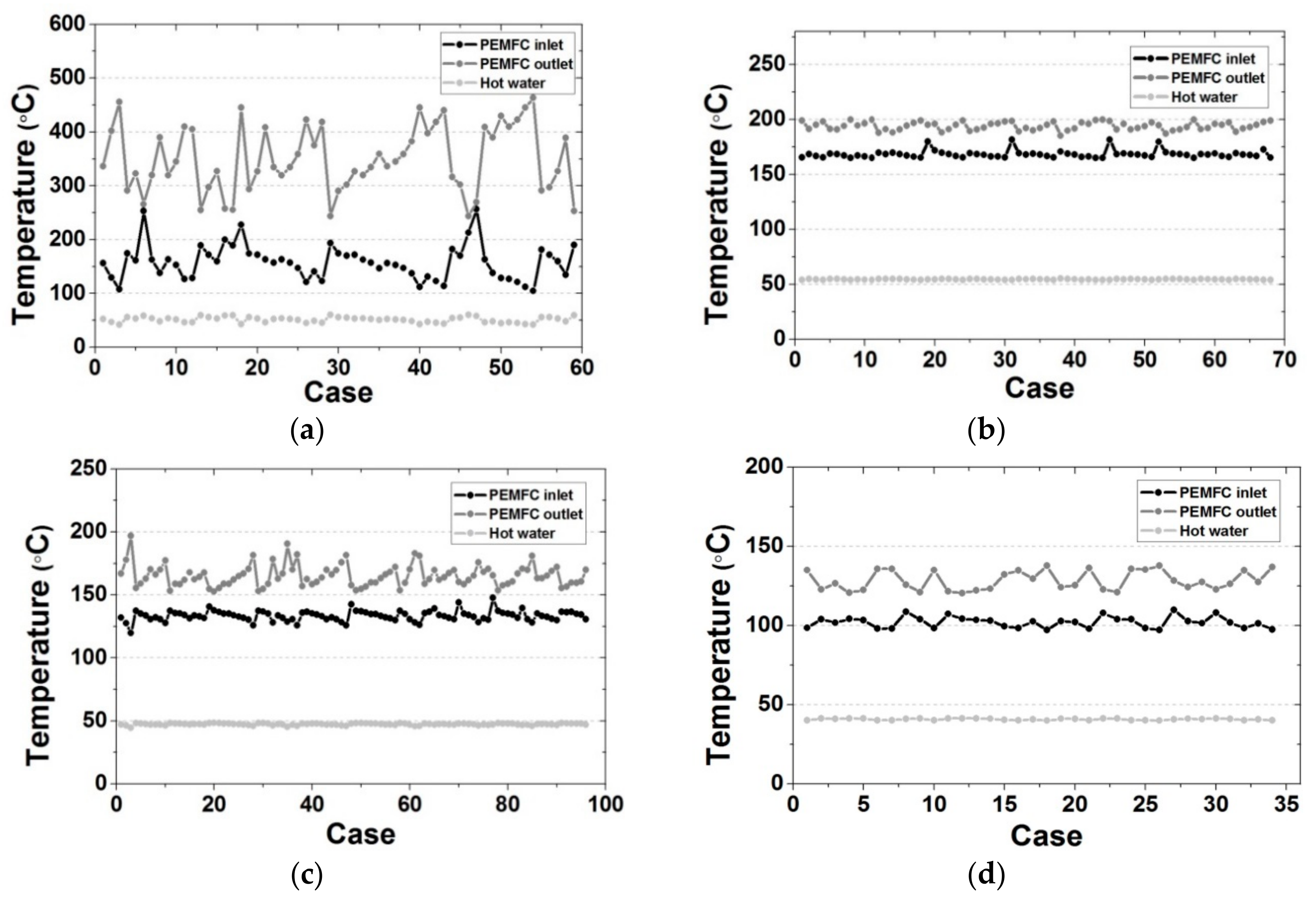
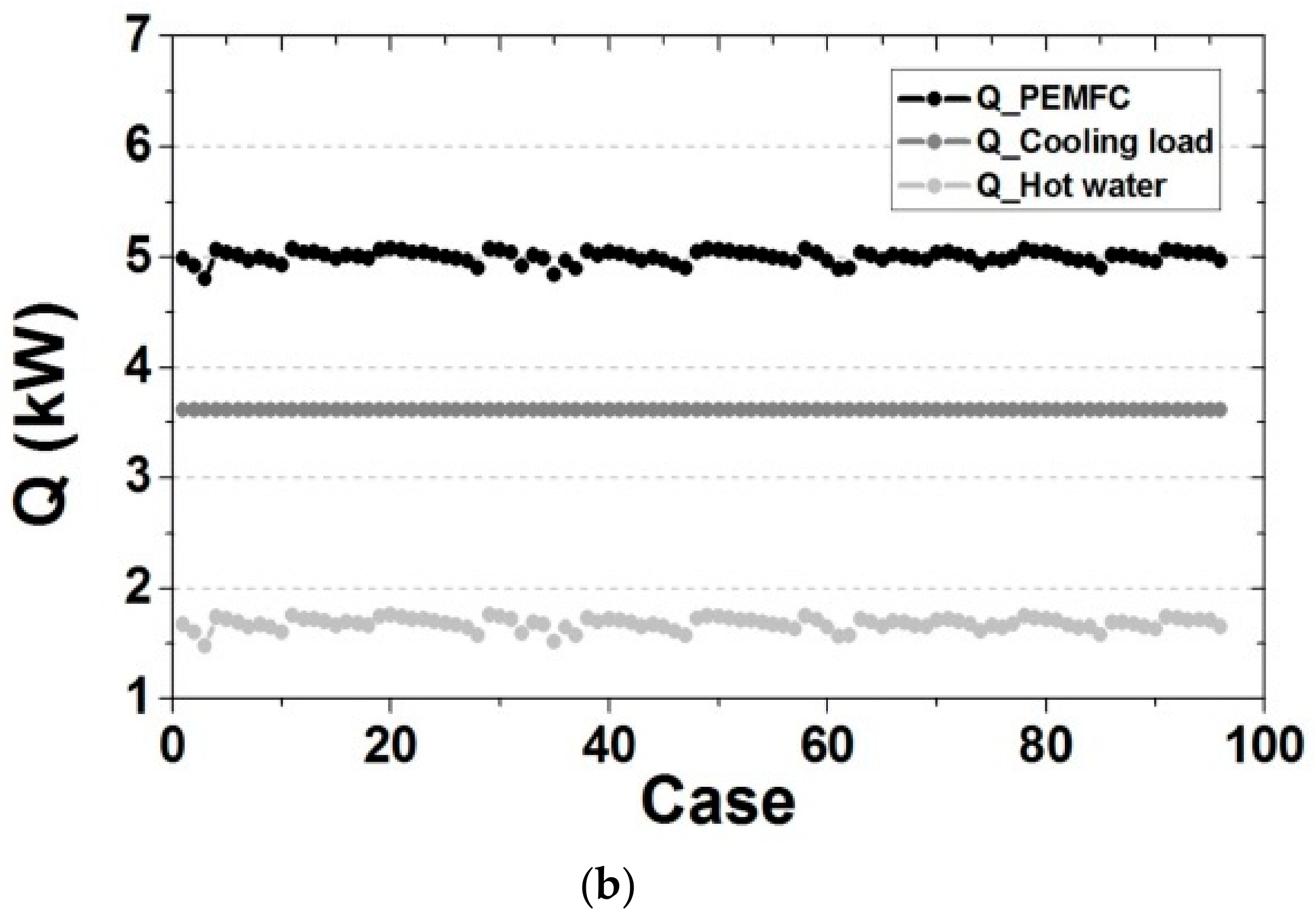
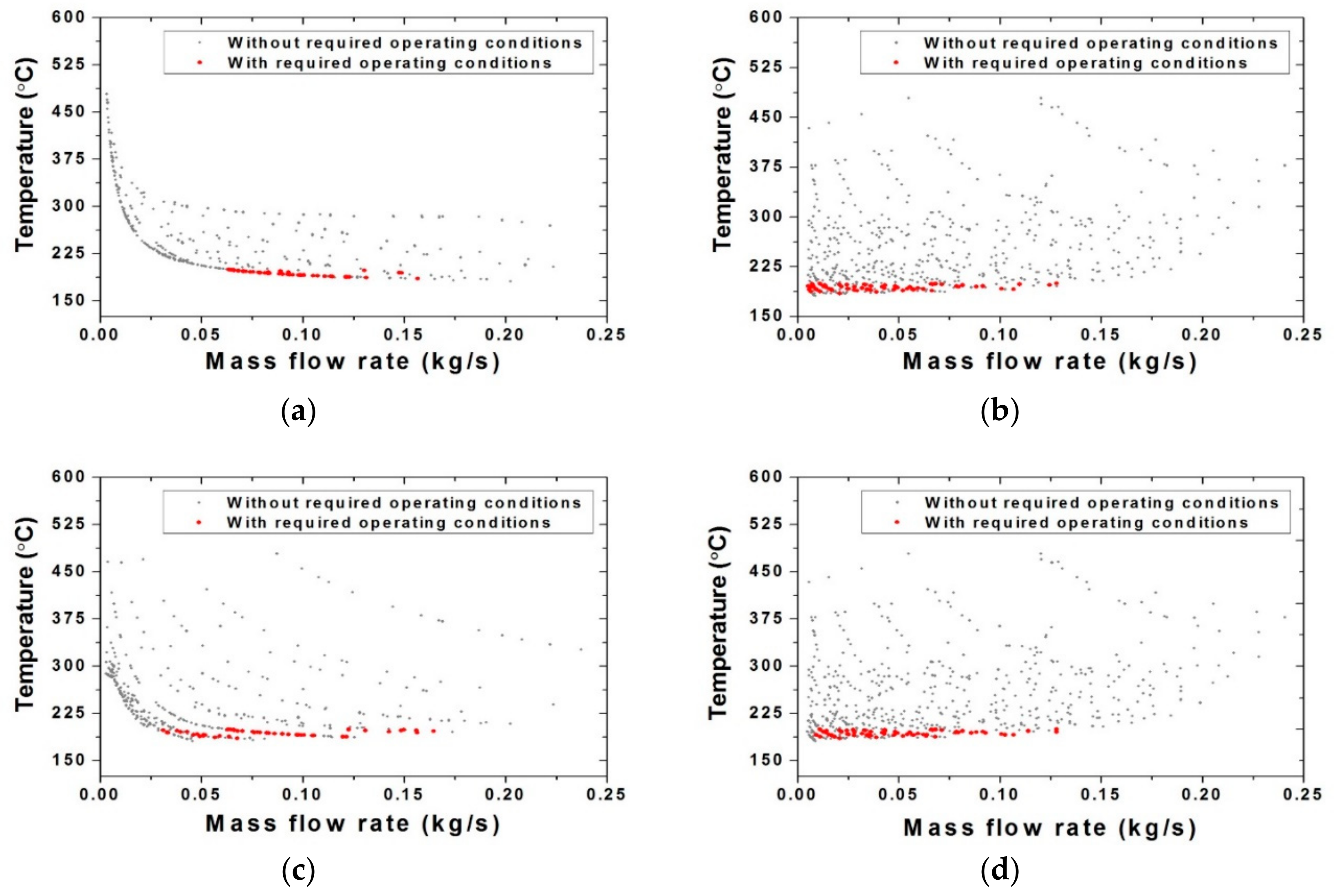
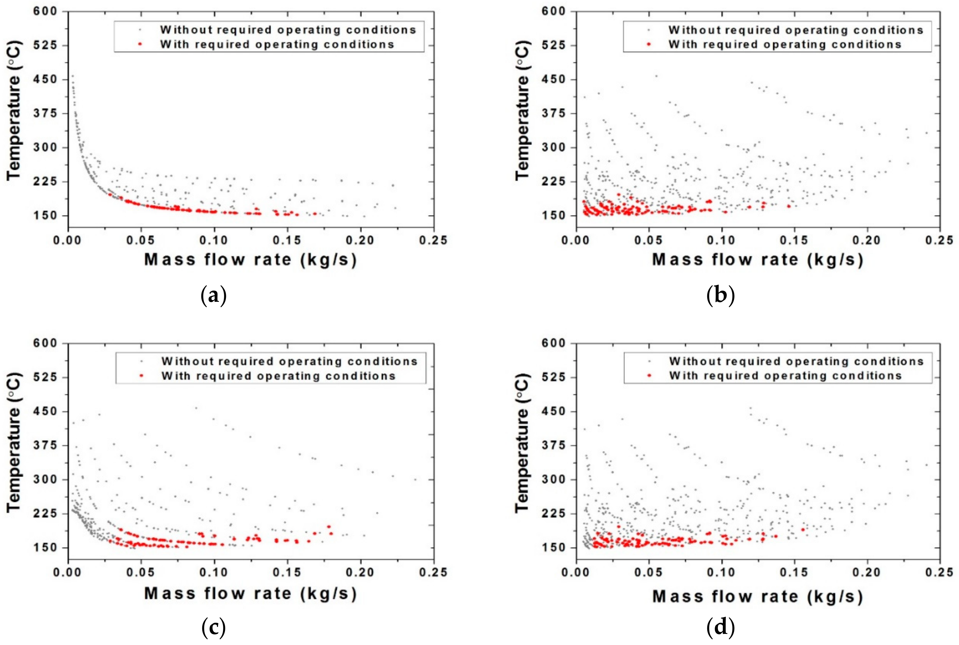
4.1. Selection of Appropriate Cooling Capacity

First, we use the integrated tri-generative system model to confirm the operating temperature change of the high-temperature PEMFC stack according to the load variation of the cooling system. We set operating conditions to ensure appropriate thermal management of the 5 kW rated stack model system as shown in Table 4. To set the flow distribution conditions for TEG (the stack thermal management and waste heat exchange fluid), we applied the opening of each valve and the operating conditions for each position of the absorption cooling system as shown in Table 5. TEG is configured to circulate through a single drive pump operating at a constant power, while the changes in stack temperature and cooling and heating load were checked through each valve control. For each operating condition, we compared whether it is possible to obtain an appropriate operating point between the stack thermal management and waste heat recovery in the tri-generative system according to the above-configured absorption cooling load.
As shown in Figure 3, we confirmed the optimal cooling capacity with the thermal management fluid distribution case satisfying the operating temperature of the stack. The cooling capacities including the required operating temperature range of the stack are 2.0 and 2.5 kW, respectively. As shown in Figure 4, the cooling capacities are 2.0 and 2.5 kW, in which the deviation of the stack load fluctuation is within 3.96% of 5 kW. Table 5 shows the valve open ratio and flow rate of each part of each case satisfying the stack operating conditions at the selected cooling capacity. Based on these selected conditions, we compared the optimum operating temperature range of the absorption cooling system, accounting for the cooling performance and stack thermal management according to the generator temperature and the concentration of the LiBr aqueous solution in the absorption cooling system.
As a result of this system analysis, the distribution of the stack outlet temperature according to the mass flow rate and corresponding to the open ratio of each valve is compared for each absorption type cooling capacity in Figure 5 and Figure 6, respectively. According to the analysis condition setting, analysis cases satisfying the required operating condition in a total of 625 analysis cases showed 68 analysis cases and 96 analysis cases when the absorption cooling capacity was 2.0 kW and 2.5 kW respectively. A relatively wide range of valve open ratios was allowed when the cooling capacity was 2.5 kW.

4.2. Comparison of Operation Conditions of Absorption Cooling System

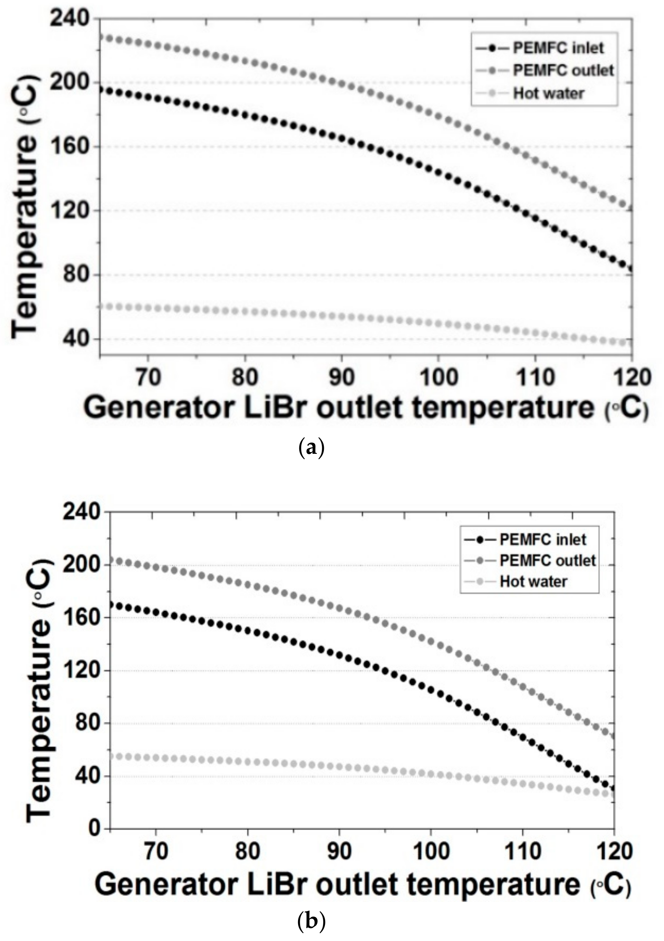
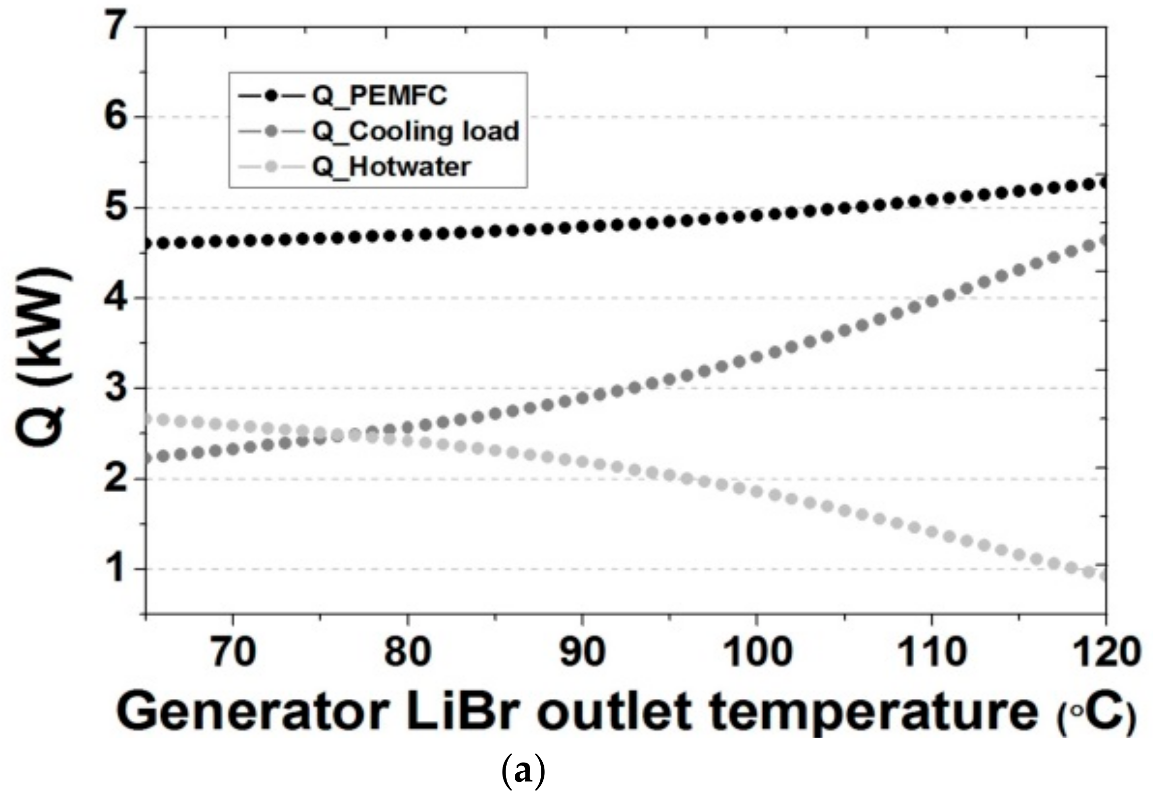
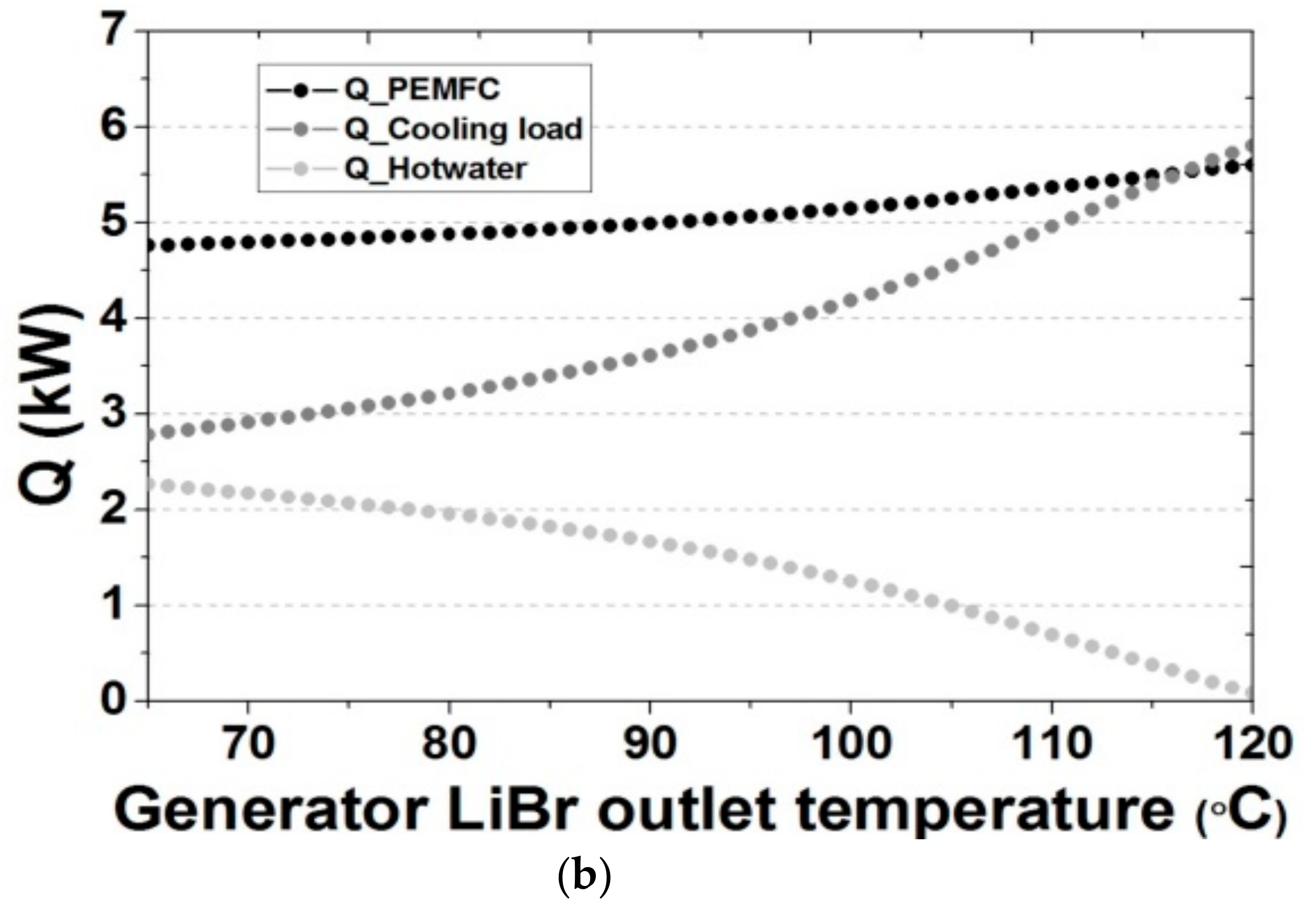
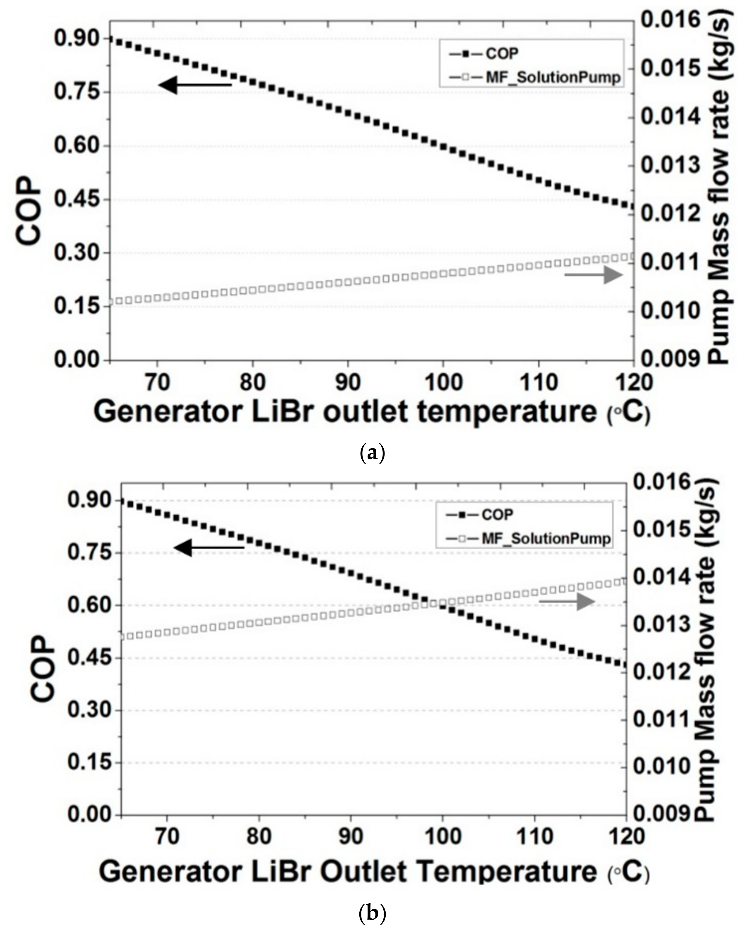
4.2.1. LiBr Aqueous Solution Temperature in Generator

In the absorption cooling system, we compared the variation of cooling performance, stack thermal management, and waste heat distribution for each system according to the concentration of the LiBr aqueous solution circulating in the generator and the absorber serving as the heat pump. Figure 7 shows the TEG and hot water (heating) temperature changes of the PEMFC stack according to the configuration of the LiBr aqueous solution temperature at the generator outlet in each cooling capacity system. Accounting for the crystallization of LiBr, the temperature range of the LiBr aqueous solution at the outlet of the generator was set to approximately 65 to 120 °C. We conservatively set the optimal range of the stack outlet TEG temperature to approximately 150–160 °C. At cooling capacities of 2.0 kW and 2.5 kW, respectively, the temperature of LiBr aqueous solution at the outlet of the generator ranged from approximately 106–111 °C and 94–97 °C, respectively. This indicates that the optimal cooling operating temperature range for stack thermal management changes according to the applied cooling capacity; thus, we were able to compare the performance and efficiency of the implemented cooling systems. Figure 8 shows the stack waste heat amount and the actual cooling and hot water (heating) load according to the temperature of the LiBr aqueous solution at the outlet of the generator. In the temperature range of LiBr aqueous solution at the outlet of the generator set in Figure 7, the cooling load was approximately 3.7–4.0 kW. Comparing the COP of the absorption cooling system according to the temperature of LiBr solution at the outlet of the generator (Figure 9), at cooling capacities of 2.0 and 2.5 kW, the COPs of the appropriate temperature range were approximately 0.47–0.52 and 0.6–0.65. Thus, we concluded that the 2.5 kW cooling system was more effective for the 5.0 kW high-temperature PEMFC stack capacity.

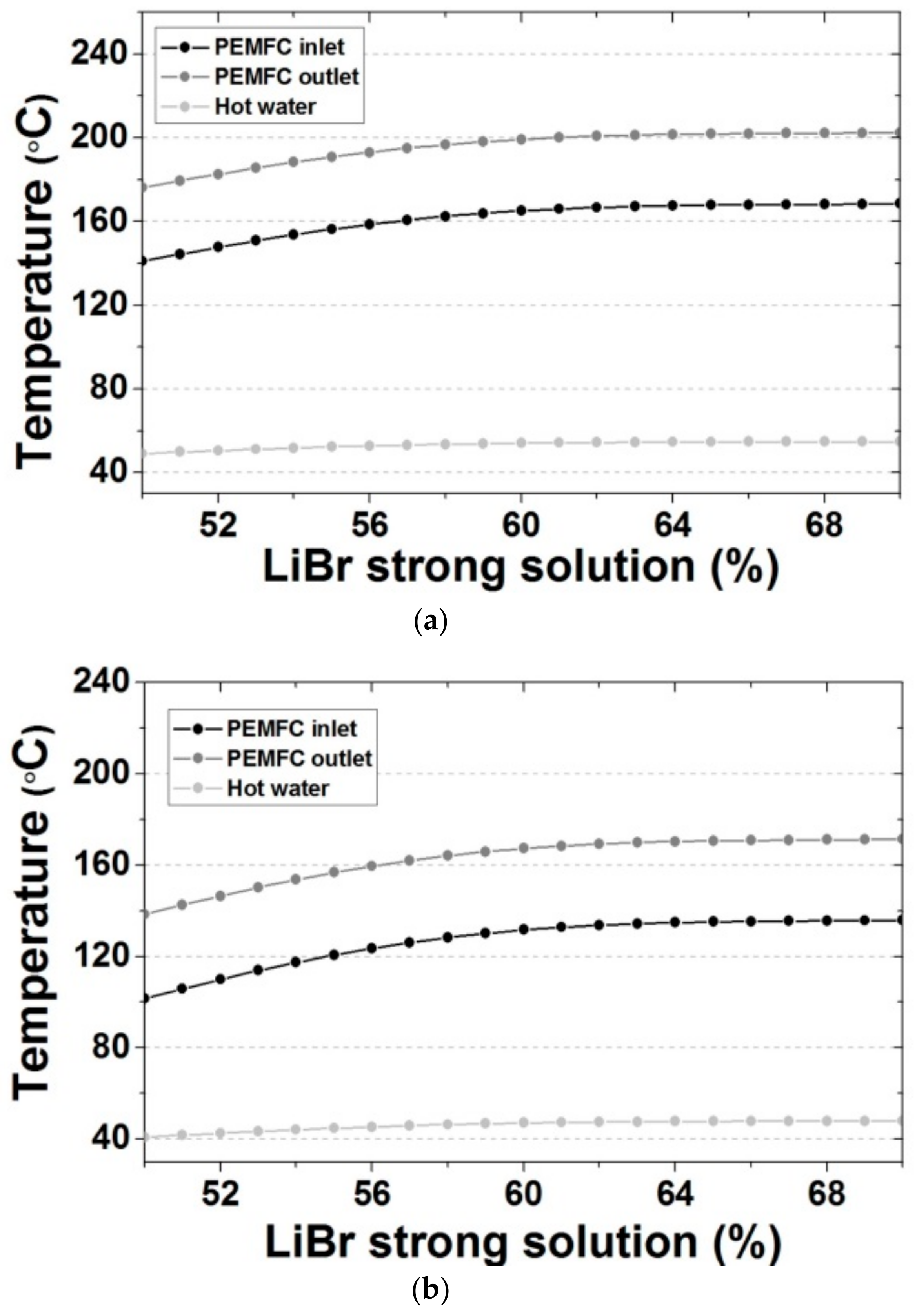
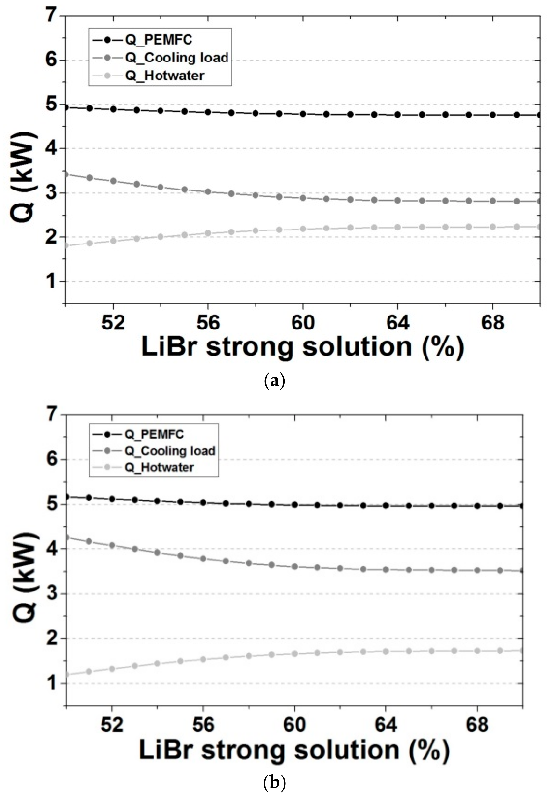
4.2.2. Concentration of LiBr Aqueous Solution

We compared the cooling performance and the load of each part of the system including the stack thermal management according to the concentration of the generator LiBr aqueous solution constituting the absorption cooling system. The temperature of the LiBr aqueous solution at the outlet of the generator was set to 90 °C; Table 5 shows the selected operating conditions excluding the high concentration side of the LiBr aqueous solution. As shown in Figure 10, at cooling capacities of 2.0 and 2.5 kW, the concentration of the LiBr aqueous solution is approximately 54–56% and 54–57%, respectively, when the stack outlet TEG temperature ranged from approximately 150–160° (review of operating conditions and generator temperature needed). Figure 11 compares the stack heating value with the load of each system according to the concentration of the LiBr aqueous solution in the generator. When the high concentration side of the LiBr aqueous solution is approximately 58% or more, the stack waste heat and the load of each system converge to an acceptable level which is common among the cooling capacity conditions.

5. Conclusions

To design a partial heat transfer (stack waste heat) fluid distribution method for a tri-generative system considering the thermal management of a high-temperature PEMFC stack, this study modeled and compared the heat transfer fluid (TEG) valve control systems according to the applied cooling capacity. Based on the selected optimal stack waste heat distribution conditions, we compared stack thermal management and the performance of the absorption cooling system. The results enabled us to determine the optimal cooling capacity and operating conditions for the high-temperature PEMFC stack applied to the tri-generative system through the cooling system.
The conclusions of this study can be summarized as follows.
(1)
We modeled the integrated thermal management tri-generative system, including a high-temperature PEMFC stack heating model and absorption cooling model, to compare the suitable operating conditions according to the stack waste heat and partial load.
(2)
When the appropriate operating range of the 5 kW high-temperature PEMFC stack model is set to about 150–160 °C, the applied cooling capacity ranged from approximately 2.0 to 2.5 kW, allowing us to set a proper flow control distribution for the partial thermal management fluid in the model.
(3)
When a 2.5 kW absorption cooling capacity is applied, considering the stack thermal management, if the operating temperature of LiBr aqueous solution at the outlet of the generator is judged to be in the appropriate range from 94 to 97 °C, then COP is expected to range from approximately 0.6–0.65.
This tri-generative system model can be improved based on the capacity and thermal management conditions of the applied high-temperature PEMFC stack, thereby contributing to the selection of initial system operating conditions and post-design operation optimization. Through experimental verification based on the operating conditions of the tri-generative system applying the improved high-temperature PEMFC stack, we plan to conduct correlation analyses with the improved model reflecting partial loss and detailed structural information.

Author Contributions

H.S.K. designed the research, H.S.K. and, Y.H.S. discussed the results and contributed to writing the paper.

Funding

This research was supported by the Technology Development Program to Solve Climate Changes of the National Research Foundation (NRF) funded by the Ministry of Science, ICT & Future Planning (NRF-2016M1A2A2937158).

Conflicts of Interest

The authors declare no conflict of interest.

References

  1. UK DECC. The Carbon Plan: Delivering Our Low Carbon Future; Presented to Parliament Pursuant to Sections 12 and 14 of the Climate Change Act 2008 Amended 2nd December 2011 from the Version Laid before Parliament on 1st December 2011; UK DECC: London, UK, 2011. [Google Scholar]
  2. Ellamla, H.R.; Staffell, I.; Bujlo, P.; Pollet, B.G.; Pasupathi, S. Current status of fuel cell based combined heat and power systems for residential sector. J. Power Sources 2015, 293, 312–328. [Google Scholar] [CrossRef]
  3. Fu, L.; Zhao, X.; Zhang, S.; Jiang, Y.; Li, H.; Yang, W. Laboratory research on combined cooling, heating and power (CCHP) systems. Energy Convers. Manag. 2009, 50, 977–982. [Google Scholar] [CrossRef]
  4. Cardona, E.; Piacentino, A. A methodology for sizing a trigeneration plant in mediterranean areas. Appl. Therm. Eng. 2003, 23, 1665–1680. [Google Scholar] [CrossRef]
  5. Ziher, D.; Poredos, A. Economics of a trigeneration system in a hospital. Appl. Therm. Eng. 2006, 26, 680–687. [Google Scholar] [CrossRef]
  6. Cardona, E.; Piacentino, A.; Cardona, F. Energy saving in airports by trigeneration. Part I: Assessing economic and technical potential. Appl. Therm. Eng. 2006, 26, 1427–1436. [Google Scholar] [CrossRef]
  7. Mago, P.J.; Fumo, N.; Chamra, L.M. Performance analysis of CCHP and CHP systems operating following the thermal and electric load. Int. J. Energy Res. 2009, 33, 852–864. [Google Scholar] [CrossRef]
  8. Tichi, S.; Ardehali, M.; Nazari, M. Examination of energy price policies in Iran for optimal configuration of CHP and CCHP systems based on particle swarm optimization algorithm. Energy Policy 2010, 38, 6240–6250. [Google Scholar] [CrossRef]
  9. De Lorenzo, G.; Fragiacomo, P. Electrical and thermal analysis of an intermediate temperature IIR-SOFC system fed by biogas. Energy Sci. Eng. 2018, 6, 60–72. [Google Scholar] [CrossRef] [Green Version]
  10. Verhaert, I.; Mulder, G.; De Paepe, M. Evaluation of an alkaline fuel cell system as a micro-CHP. Energy Convers. Manag. 2016, 126, 434–445. [Google Scholar] [CrossRef]
  11. Kwan, T.H.; Yao, Q. Exergetic and temperature analysis of a fuel cell-thermoelectric device hybrid system for the combined heat and power application. Energy Convers. Manag. 2018, 173, 1–14. [Google Scholar] [CrossRef]
  12. Mehrpooya, M.; Sadeghzadeh, M.; Rahimi, A.; Pouriman, M. Technical performance analysis of a combined cooling heating and power (CCHP) system based on solid oxide fuel cell (SOFC) technology—A building application. Energy Convers. Manag. 2019, 198, 111767. [Google Scholar] [CrossRef]
  13. Ebrahimi, M.; Derakhshan, E. Thermo-environ-economic evaluation of a trigeneration system based on thermoelectric generator, two-bed adsorption chiller, and polymer exchange membrane fuel cell. Energy Convers. Manag. 2019, 180, 269–280. [Google Scholar] [CrossRef]
  14. Cozzolino, R. Thermodynamic Performance Assessment of a Novel Micro-CCHP System Based on a Low Temperature PEMFC Power Unit and a Half-Effect Li/Br Absorption Chiller. Energies 2018, 11, 315. [Google Scholar] [CrossRef]
  15. Dicks, A.; Pointon, K.; Siddle, A. Intrinsic reaction kinetics of methane steam reforming on a nickel/zirconia anode. J. Power Sources 2000, 86, 523–530. [Google Scholar] [CrossRef]
  16. Bhatia, K.K.; Wang, C.-Y. Transient carbon monoxide poisoning of a polymer electrolyte fuel cell operating on diluted hydrogen feed. Electrochim. Acta 2004, 49, 2333–2341. [Google Scholar] [CrossRef]
  17. Araya, S.S.; Andreasen, S.J.; Kær, S.K. Experimental Characterization of the Poisoning Effects of Methanol-Based Reformate Impurities on a PBI-Based High Temperature PEM Fuel Cell. Energies 2012, 5, 4251–4267. [Google Scholar] [CrossRef]
  18. Devanathan, R. Recent developments in proton exchange membranes for fuel cells. Energy Environ. Sci. 2008, 1, 101. [Google Scholar] [CrossRef]
  19. Chandan, A.; Hattenberger, M.; El-Kharouf, A.; Du, S.; Dhir, A.; Self, V.; Pollet, B.G.; Ingram, A.; Bujalski, W. High temperature (HT) polymer electrolyte membrane fuel cells (PEMFC)—A review. J. Power Sources 2013, 231, 264–278. [Google Scholar] [CrossRef]
  20. Authayanun, S.; Im-Orb, K.; Arpornwichanop, A. A review of the development of high temperature proton exchange membrane fuel cells. Chin. J. Catal. 2015, 36, 473–483. [Google Scholar] [CrossRef]
  21. Liang, H.; Su, H.; Pollet, B.G.; Pasupathi, S. Development of membrane electrode assembly for high temperature proton exchange membrane fuel cell by catalyst coating membrane method. J. Power Sources 2015, 288, 121–127. [Google Scholar] [CrossRef]
  22. Rosli, R.; Sulong, A.; Daud, W.; Zulkifley, M.; Husaini, T.; Rosli, M.; Majlan, E.; Haque, M.; Rosli, M. A review of high-temperature proton exchange membrane fuel cell (HT-PEMFC) system. Int. J. Hydrogen Energy 2017, 42, 9293–9314. [Google Scholar] [CrossRef]
  23. Korsgaard, A.R.; Bang, M.; Kær, S.K.; Nielsen, M.P. Modeling of CO Influence in PBI Electrolyte PEM Fuel Cells. In Proceedings of the ASME 2006 4th international conference on fuel cell science, engineering and technology, Irvine, CA, USA, 19–21 June 2006; pp. 911–915. [Google Scholar]
  24. Arsalis, A.; Nielsen, M.P.; Kær, S.K. Modeling and off-design performance of a 1kWe HT-PEMFC (high temperature-proton exchange membrane fuel cell)-based residential micro-CHP (combined-heat-and-power) system for Danish single-family households. Energy 2011, 36, 993–1002. [Google Scholar] [CrossRef]
  25. Chang, H.; Wan, Z.; Zheng, Y.; Chen, X.; Shu, S.; Tu, Z.; Chan, S.H.; Chen, R.; Wang, X. Energy- and exergy-based working fluid selection and performance analysis of a high-temperature PEMFC-based micro combined cooling heating and power system. Appl. Energy 2017, 204, 446–458. [Google Scholar] [CrossRef] [Green Version]
  26. Rogers GF, C.; Mayhew, Y.R. Thermodynamic and Transport Properties of Fluids; Blackwell: Hoboken, NJ, USA, 1995. [Google Scholar]
  27. ASHRAE. ASHRAE Handbook-1993 Fundamentals; ASHRAE: Atlanta, GA, USA, 1993. [Google Scholar]
Figure 1. Schematic diagram of the Tri-generative system.
Energies 12 03145 g001
Figure 2. Simulation design of tri-generative system using FloMaster.
Energies 12 03145 g002
Figure 3. Comparison of PEMFC in/out TEG and hot water temperature by case according to absorption cooling performance. (a) Absorption cooling capacity: 1.5 kW; (b) Absorption cooling capacity: 2.0 kW; (c) Absorption cooling capacity: 2.5 kW; (d) Absorption cooling capacity: 3.0 kW.
Energies 12 03145 g003
Figure 4. Comparison of PEMFC stack heating value, cooling, and hot water (heating) load by absorption cooling performance. (a) Absorption cooling capacity: 2.0 kW; (b) Absorption cooling capacity: 2.5 kW.
Energies 12 03145 g004aEnergies 12 03145 g004b
Figure 5. Stack outlet temperature according to flow rate of each valve (Absorption cooling capacity 2.0 kW). (a) TM valve; (b) IC valve; (c) CHP valve; (d) CCP valve.
Energies 12 03145 g005
Figure 6. Stack outlet temperature according to flow rate of each valve (Absorption cooling capacity 2.5 kW). (a) TM valve; (b) IC valve; (c) CHP valve; (d) CCP valve.
Energies 12 03145 g006
Figure 7. Comparison of PEMFC in/out TEG and hot water temperature according to the temperature of the LiBr solution at the generator outlet of absorption cooling system. (a) Absorption cooling capacity: 2.0 kW; (b) Absorption cooling capacity: 2.5 kW.
Energies 12 03145 g007
Figure 8. Comparison of stack heating value, cooling and hot water (heating) load according to LiBr solution temperature at the outlet of the generator of absorption cooling system. (a) Absorption cooling capacity: 2.0 kW; (b) Absorption cooling capacity: 2.5 kW.
Energies 12 03145 g008aEnergies 12 03145 g008b
Figure 9. Comparison of cooling efficiency and LiBr aqueous solution transfer rate according to the temperature of the LiBr solution at the generator outlet of absorption cooling system. (a) Absorption cooling capacity: 2.0 kW; (b) Absorption cooling capacity: 2.5 kW.
Energies 12 03145 g009
Figure 10. Comparison of stack in/out TEG and hot water temperature according to generator outlet LiBr aqueous solution concentration of absorption cooling system. (a) Absorption cooling capacity: 2.0 kW; (b) Absorption cooling capacity: 2.5 kW.
Energies 12 03145 g010
Figure 11. Comparison of stack heating value, cooling and hot water (heating) load according to generator outlet LiBr aqueous solution concentration of absorption cooling system. (a) Absorption cooling capacity: 2.0 kW; (b) Absorption cooling capacity: 2.5 kW.
Energies 12 03145 g011
Table 1. Operating parameters and empirical parameters used in HT-PEMFC model.
ParametersValues
Number of cells, N80
Operating temperature, Tcell (°C)160
Current density, I (A/cm2)0.85
Air stoichiometry, λair3
Single cell active area, Acell (cm2)100
Open circuit Voltage, Vocv (V)0.95
Ideal gas constant, R (J/mol·K)8.314
Faraday constant, F96,485.3
Exchange current density, I0 (A/cm2)0.000202
Anode charge transfer coefficient, αa0.5
Cathode charge transfer coefficient, αc0.25
Hydrogen electro-oxidation rate constant, keh, (A/cm2)1.63818
Hydrogen surface coverage, θh20.14212
High heating Value of hydrogen, HHV (kJ/mol)282.63
Table 2. Design parameters used in Libr-water absorption model.
ParametersValues
Absorption cooling capacity, Qe (kW)3
Evaporator outlet temperature, T20 (°C)6
Generator solution outlet temperature, T14 (°C)90
LiBr weak solution mass fraction, X11 (%)55
LiBr strong solution mass fraction, X14 (%)60
Generator solution inlet temperature, T13 (°C)65
Generator vapor outlet temperature, T17 (°C)85
Liquid mass flow rate from evaporator, m ˙ 20 0.025 ×   m ˙ 21
Table 3. Simulation result of Absorption refrigerator cycle.
PointPressure (kPa)Temperature (°C)Enthalphy (kJ/kg)LiBr (%)Mass Flow (kg/s)
110.934334.8683.02550.01591
129.65734.8683.02550.01591
139.65765145.4550.01591
149.65790212.2600.01459
159.65754.75144.2600.01459
160.934344.49144.2600.01459
179.65785262700.001326
189.65744.3118900.001326
190.9343618900.001326
200.93436251200.001294
210.9343625.1600.00003235
Table 4. Appropriate operating conditions of high-temperature PEMFC stack system.
ParametersValues
Heat balance of total system (kW)±0.5
TEG temperature, TTEG (°C)-7 < TTEG
Stack outlet temperature, TS-out (°C)150 < TS-Out < 200
Hot water temperature, Thw (°C)40 < Thw
Table 5. Open ratio of thermal management fluid distribution valves and operating conditions of the heating and cooling system.
ParametersValues
Absorption cooling capacity, Qe (kW)1.5, 2.0, 2.5, 3.0
TEG valve open ratio for stack cooling, ORTM0.1, 0.3, 0.5, 0.7, 0.9
TEG valve open ratio for pump bypass, ORIC
TEG valve open ratio for hot water (or heat), ORCHP
TEG valve open ratio for absorption cooling, ORCCP
TEG pump power, PTEG (kW)0.288

