1. Introduction
Photovoltaic (PV) systems use solar radiation to convert solar radiation into electricity, but untransformed absorbed solar radiation increases the PV cell temperature and reduces the electrical efficiency of the system. Therefore, photovoltaic/thermal (PVT) collectors have been developed that circulate air and liquid behind the PV panel. The PVT system integrates the solar cell and space through which the heat transfer medium flows, thereby efficiently utilizing the heat generated from the rear air gap of the PV simultaneously with electricity production at the front PV module. PVT systems are classified as air-type and liquid-type based on the thermal medium. Among these, the air-type PVT system has advantages in that it does not cause problems of leakage or freezing because air is used as the heating medium. In addition, unlike liquid type PVT, air-type PVT is easy to apply to buildings because there are few additional facilities to be installed, and when an air-type building integrated photovoltaic/thermal (BIPVT) is applied as a finishing material on a facade of a building, there is an advantage that building energy can be covered at the same time.
The electrical and thermal efficiencies of air-type PVT collectors have been analyzed and found to 9%–12% and 40%–60%, respectively [
1]. To increase the efficiency of air-type PVT, numerical analysis modeling and research experiments to evaluate the performance of collectors have been carried out steadily. Calise et al. developed software that analyzes the quantitative performance of collectors as a function of key design/environmental variables through sensitivity analysis of the PVT collector; they also analyzed the experimental performance [
2]. Ooshaksaraei et al. evaluated the energy and exergy performance of four air-based bifacial photovoltaic thermal collectors with four flow paths in the collector. Collector model with two (double-path parallel flow) had the highest total energy efficiency (51%–67%), followed by model three (double-path counter flow; 47%–62%), model four (single-path returning flow; 42%–56%), and model one (single-path; 28%–49%) [
3]. Based on theoretical and experimental investigations on exergy of a PVT/TE (photovoltaic thermal/thermoelectric) system, Nazri et al. confirmed that the thermal exergy decreased while the PV exergy increased according to an increasing flow rate. Therefore, it was concluded that the temperature was an important factor affecting the conversion efficiency of the system. The results of this simulation showed that an increase in the overall power output and conversion efficiency may be achieved by incorporating TE to harvest heat from the PV cell. The exergy efficiency of the PVT collector of previous studies was 4%–18%, but the exergy efficiency of PVT/TE increased to 38% [
4]. An air-type PVT system uses a method of changing the air flow inside the collector to increase the collection efficiency. In a study by Mohamed et al., four solar collectors—a PV module, air-type PVT, glazed PVT, and double pass glazed PVT –were compared. The resulting values of the daily average total energy efficiency were 26.6%, 51.0%, 69.5%, and 74.0%, respectively [
5].
In other papers, a baffle was installed in the collector to prolong the air retention time and generate turbulence, contributing to efficiency improvement. Hu et al. analyzed the effects on collector performance of the number of baffles installed in the collector, the thickness of the air layer, and the operating conditions [
6]. Mojumder et al. also analyzed the thermal and electrical performance of the PVT system to improve the PV electrical efficiency by 0.81% and the thermal efficiency by up to 56% depending on the presence or absence of fins in the collector under various conditions [
7]. Yadav et al., using a computational fluid dynamics (CFD) program, studied air heat transfer inside a collector of a triangular baffle mounted on an absorber; they found that the Nusselt number increased 1.4 to 2.7 times compared to that of a collector without a baffle [
8], Kumar et al. investigated the thermal performance when using a V-shaped baffle and various parameters (baffle width, width, height, and Reynolds number) [
9].
Other studies have combined air-type PVT collectors and building facility systems have evaluated the performance of the preheated air source and the electrical energy obtained from the power generation for building energy. Hailu et al. used the TRNSYS program to compare the performance of the existing ASHP (air source heat pump) and air-type BIPVT with ASHP. They found a COP (coefficient of performance) improvement that was confirmed when the ambient temperature was above −3 °C [
10]. Barone et al. designed a low-cost air-based PVT collector and developed a dynamic simulation model to analyze energy performance and economics under various operating conditions. The developed simulation model was implemented in Matlab code, and the collector was connected to an air-to-air heat pump for indoor heating of a sample building. The results depicted the effectiveness of the proposed system, namely; estimated primary energy savings were 11.0–19.7 MWh/year corresponding to 52%–80%, reduction in carbon dioxide emissions was 4.64–10.4 tCO
2/year, and the simple pay-back period of 3.2–4.8 years was estimated [
11].
Li et al. studied an efficient integration approach of a BIPVT system combined with HVAC (heating, ventilation, and air conditioning) and storage systems. On a sunny day, the heat pump operates to meet the heating requirements of the building and charges the energy produced by the BIPVT system into the thermal energy storage (TES) tank during the day. The total electrical energy consumption for three days was 84 kWh, the heating load for four days was 690.3 kW, and the total energy savings was 17.4% [
12]. In the study of Kim et al., a 1 kWp collector was installed to evaluate the performance of an air-type PVT system combined with an HRV (heat recovery ventilator). The overall efficiency (heat and electricity efficiency) during the heating period was 38%, and thermal energy was reduced by 10% compared to that of the existing HRV-only system [
13]. Sukamongkol et al. designed a model with a pneumatic PVT collector and a condenser heat recovery system. At the same time as electricity was produced by PV, the air source, preheated from the back of the PV module, and the heat source of the condenser were mixed and air (gas refrigerant) for inducing high temperature in the compressor was completely dehumidified. Consequently, the energy used in the air conditioner was reduced by about 18% [
14].
Existing research on air-type PVT collectors has mainly focused on improving the efficiency of the collector itself and on performance using energy produced by collectors in building cooling and heating facilities, as well as building energy. However, the first thing to consider when actually applying such a system to a building is the method of connecting the collector and the connection path. It is necessary to design the flow inside the air-type BIPVT collector smoothly because there is a dead space that deteriorates the thermal performance of the collector and a pressure drop that occurs inside the collector if these factors are not taken into consideration.
Therefore, through a simulation program (NX CFD), this study analyzed the air flow characteristics of an air-type BIPVT collector installed in a demonstration building and analyzed the thermal characteristics of the air-type BIPVT collector through demonstration experiments.
2. Demonstration and Air-type BIPVT models
2.1. Demonstration Site
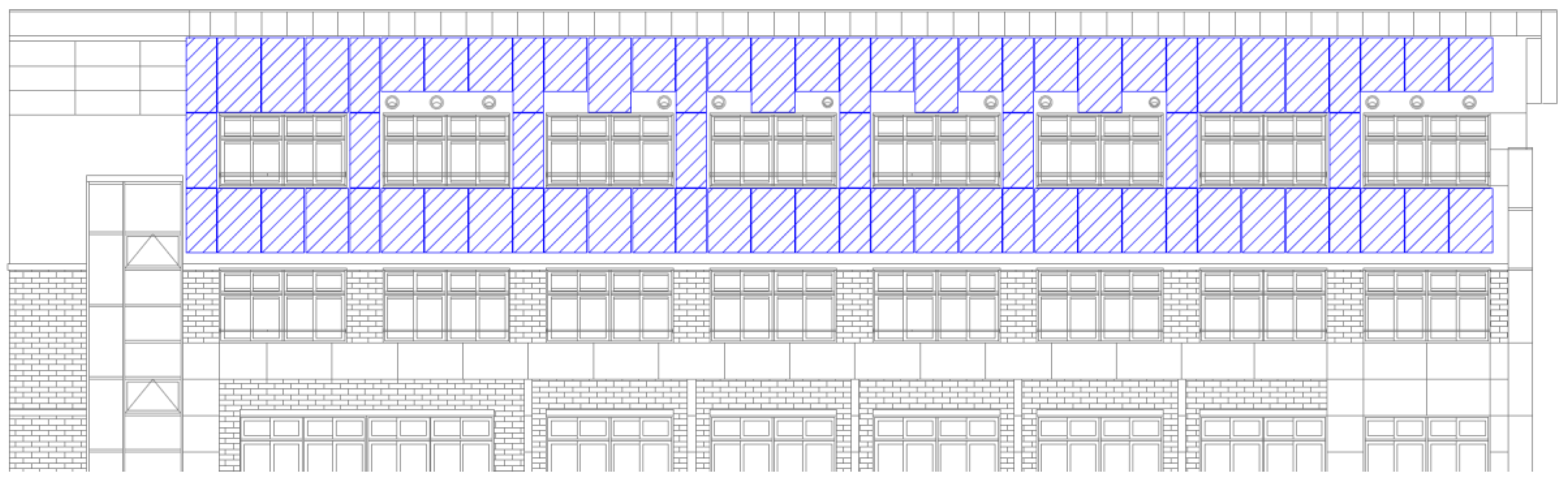
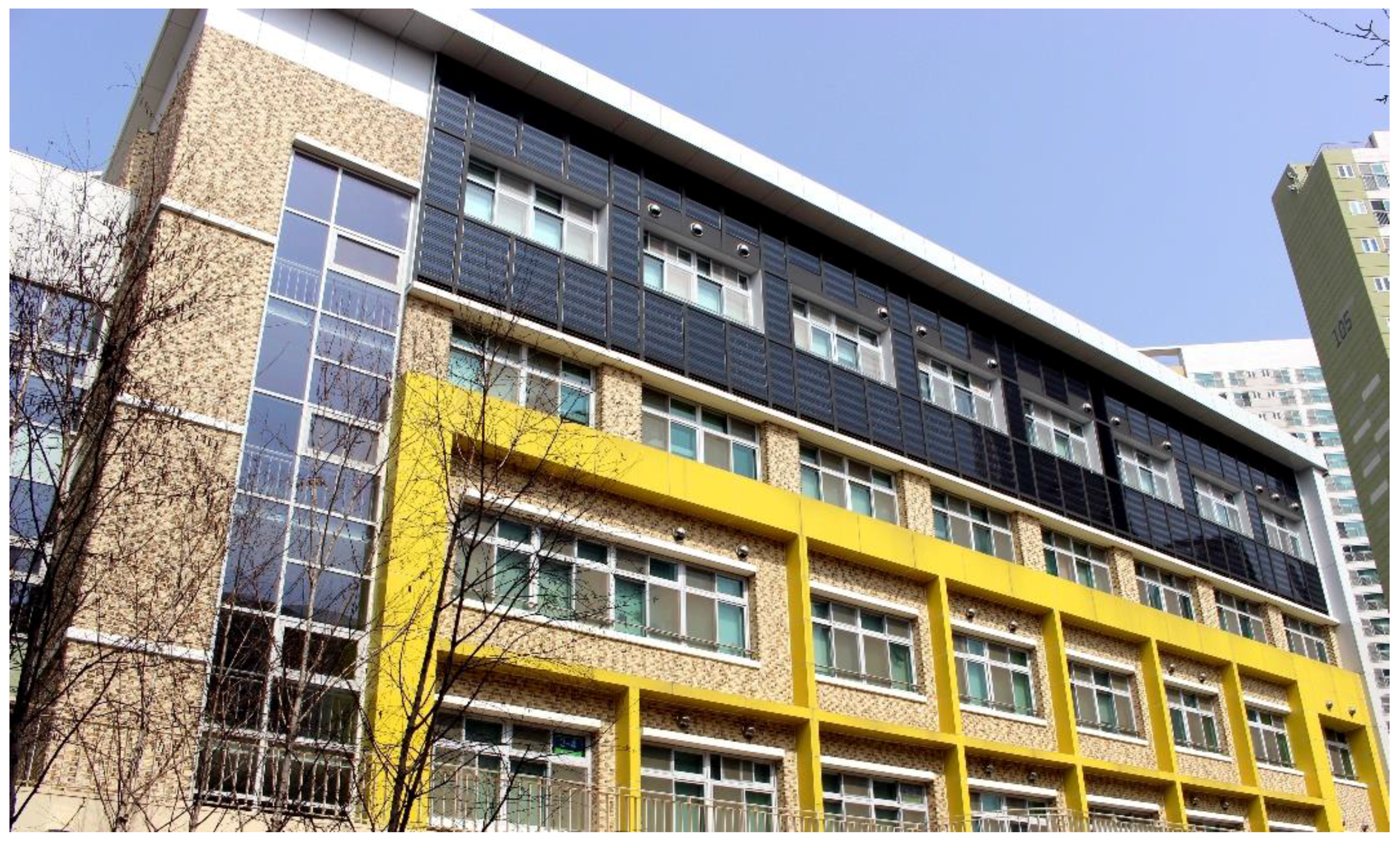
In this study, an air-type BIPVT collector was installed in an extension building of an elementary school (educational research facility) in Cheonan, Korea (36.84° N, 127.11° E). The target building had an air-type BIPVT collector installed on the southern side of the building, and had been expanded from a four-story building to a five-story building. The floor area of the enlarged building was 768.02 m
2, mainly used as classrooms. An electric heat pump (EHP) and HRV were combined with the air conditioning system, and the operation schedule of the system was from Monday to Friday from 9:00 a.m. to 4:00 p.m. (
Figure 1 and
Figure 2).
Air-type BIPVT collectors were installed on the south side of the building, with an area of about 123 m
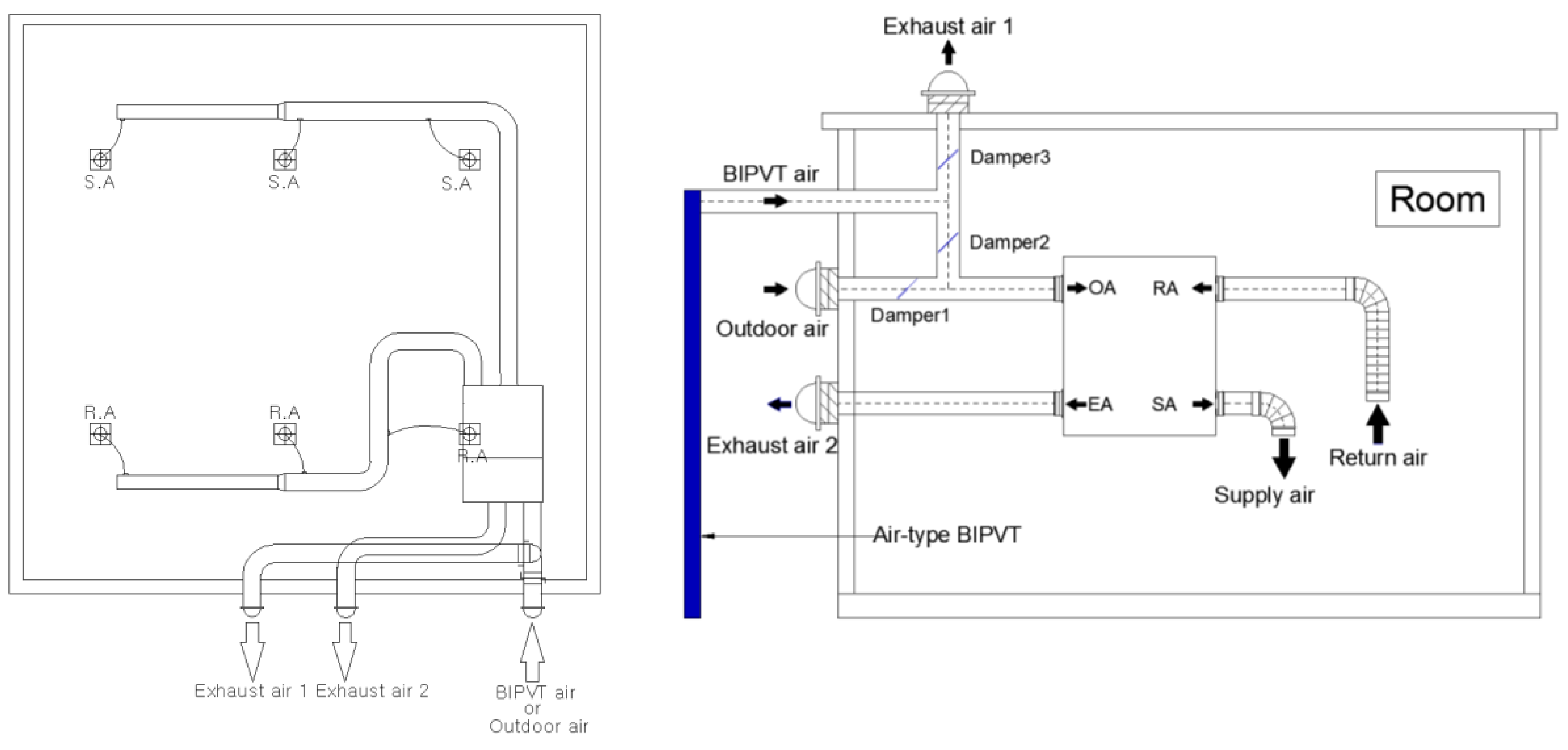
2 in total, at the elevation of the four classrooms. The PV generation capacity of the 72 collectors installed was 10 kWp. The electricity generated was directly used in the building, and the preheated air was used as a heat source for the building load. Two classrooms were linked to an air handling unit (AHU) that used preheated air as a heat source for ventilation and heating from the collector (
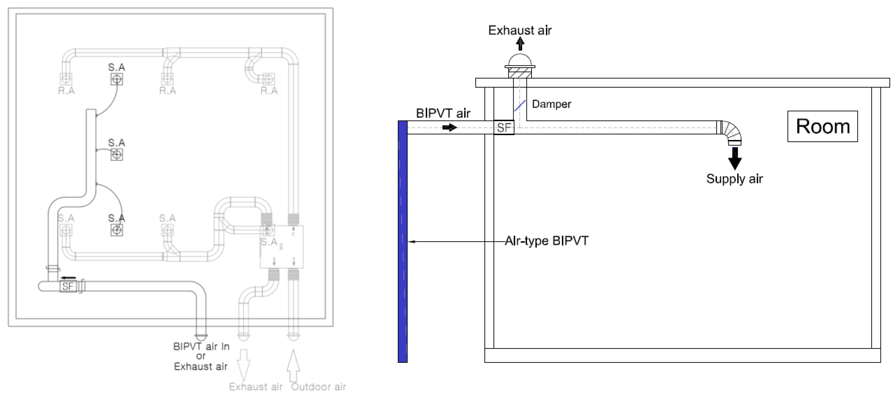
Figure 3). The air supply temperature was determined by controlling the flow rate of the air supplied from the outside to the BIPVT by controlling the sensible heat of the outside temperature and the set indoor temperature. Proportional control was performed using a damper to adjust the set indoor air temperature. In the other two classrooms, the method of operation was to use the air heat source directly or to exhaust it (
Figure 4).
In
Figure 3, the AHU acts as a fan (500 m
3/h) in the air-type BIPVT system. Therefore, the preheated air can flow into the classroom and can mix with outdoor air by the open ratio of dampers trough PID (Proportional-Integral-Differential)-control. The BIPVT system in
Figure 4 was equipped with a supply fan (SF, 500 m
3/h) to allow preheated air to enter the room.
Air-type BIPVT collectors of five types were installed on the facades of the demonstration buildings.
2.2. Air-type BIPVT Collector
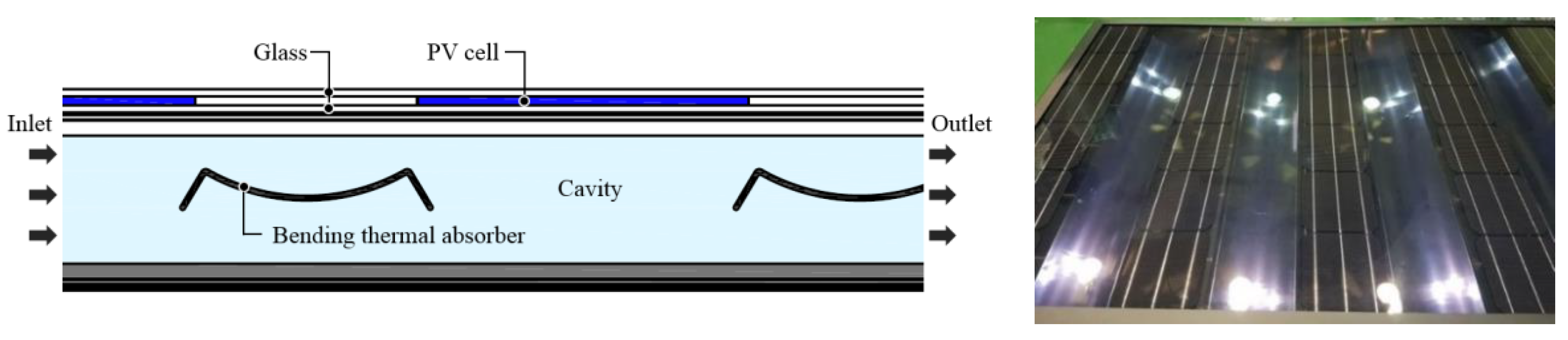
The air-type BIPVT collector designed for this study is shown in
Figure 5. Unlike existing commercial modules, which are covered with PV cells, this model had PV cells and glass alternately arranged in the module. Each module consisted of about 36 monocrystalline silicon solar cells between two glass layers (glass to glass). A thermal absorber made of a thin sheet of metal coated with blue inside the collector is installed at the intersection of the PV cell. Thus, solar radiation can reach the thermal absorber directly through the glass. The absorber is designed in the form of a curved surface so that solar energy can be incident at any angle. These plates act as baffles and help ensure smooth airflow inside the collector. This feature allows solar energy to enter and flow well even if the air-type BIPVT collector is installed vertically on the building’s facade. Thus, the thermal performance of the collector can be increased.
2.3. Simulation Modeling of Air-Type BIPVT
To analyze the internal flow and thermal characteristics of the coupled air-type BIPVT collector, it was modeled through a flow analysis simulation program, the NX program, and the collector performance was compared and analyzed by CFD analysis after dividing the mesh. NX is a program that simulates fluid flow effects; it can rapidly generate flow regions of complex geometry and perform computational fluid dynamics [
15].
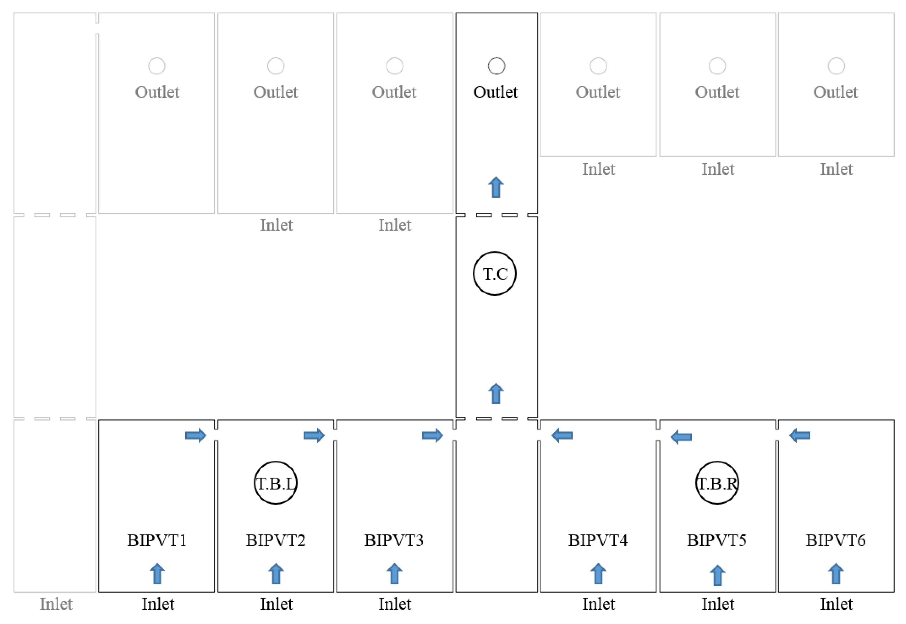
Figure 6 shows the internal flow path of an air-type BIPVT collector integrated to the facade of one classroom with three flow paths. In the figure, the flow path marked in bold provides a connection between the air-type BIPVT collectors and forms a “⊥” type flow path. In the figure, the flow path marked in bold provides a connection path between the pneumatic BIPVT collector and the collector and forms a “⊥” type flow path. This flow path can be disadvantageous to the internal flow characteristics of the fan at the outlet. Therefore, the air flow was analyzed by setting the inlet opening ratio for each collector so that the air would flow smoothly. Ambient air is introduced at the lower BIPVT 1–6 (six collectors) and the fluid is discharged through connected collectors to the upper outlet (D 150 mm).
For the simulation analysis, four cases were designed with different opening ratios of air-type BIPVT 1–6. When the collector’s inlet opening ratio was 100%, the inlet area was 0.0755 m
2; in all cases, BIPVT 1 and BIPVT 6 were the same, when the opening ratio was 100%. The opening ratios of BIPVT 2 and 5 were reduced to 100%, 50%, 25%, and 10% depending on cases (
Table 1), and the opening ratios of BIPVT 3 and 4 were reduced by half (100%, 25%, 13%%, and 5%) compared to those of BIPVT 2 and 5. The opening ratio of the inlet near the outlet was reduced so that the air flow could be evenly distributed from the outlet to the far collector.
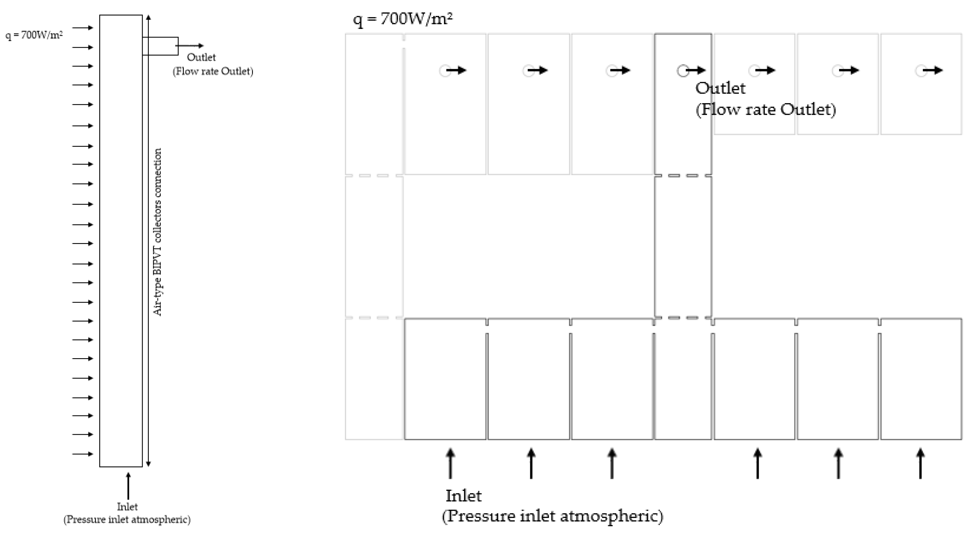
In order to set up four cases according to the inlet opening ratio, the inlet area was reduced and modeled. For simulation of the air-type BIPVT collector, the collector area was set at 14.28 m
2, and thermal energy of 500 W per unit area was equally supplied to each case. In order to consider the surface heat loss of the collector, the outside temperature value was used as the input. The air density to be applied according to the temperature was specified at 1.225 kg/m
3 (when the temperature was 25 °C). The gravity acceleration value was 9.81 m/s
2 and buoyancy was applied. The computational domain and simulation conditions of the air-type BIPVT collector connection are showed
Figure 7 and
Table 2.
For the meshing strategy, the automatic meshing method was selected, which is a combination of the tetrahedron (patch matching) and sweep method. The sweep mesh of the collector not only reduces the count, but also provides a mesh that fits well with the flow. To capture the boundary layer, an expansion layer of the collector wall was used.
Mostly for the heat transfer fluid problems, the grid independence test was performed by considering average outlet temperature of the air-type BIPVT collector. Similarly, the simulation results were considered as grid independent as far as the temperature of BIPVT collector is concerned. The grid independence test was performed using four different grids having different number of elements such as 479,353, 643,112, 1,103,630, and 3,416,589, respectively. Averaging the temperature values obtained 43.13, 41.55, 41.87, and 41.59. It can be seen that the last three grids had an insignificant percentage difference between them that was approximately less than one percent. Therefore, the adequate grid of 643,112 elements was selected for computation.
The turbulence model used was the K-Epsilon model, the most common turbulence model, where k is the turbulent kinetic energy and ε is the dissipation rate of turbulent energy. This model is based on the time-averaged Navier–Stokes equations, which assumes that the time-varying velocities of turbulence can be divided into time-averaged velocities and velocity-dependent velocities. Therefore, the model itself is simple, which is advantageous in terms of calculation convergence [
16].
2.4. Analysis of Simulation Results
2.4.1. Heat Transfer Performance
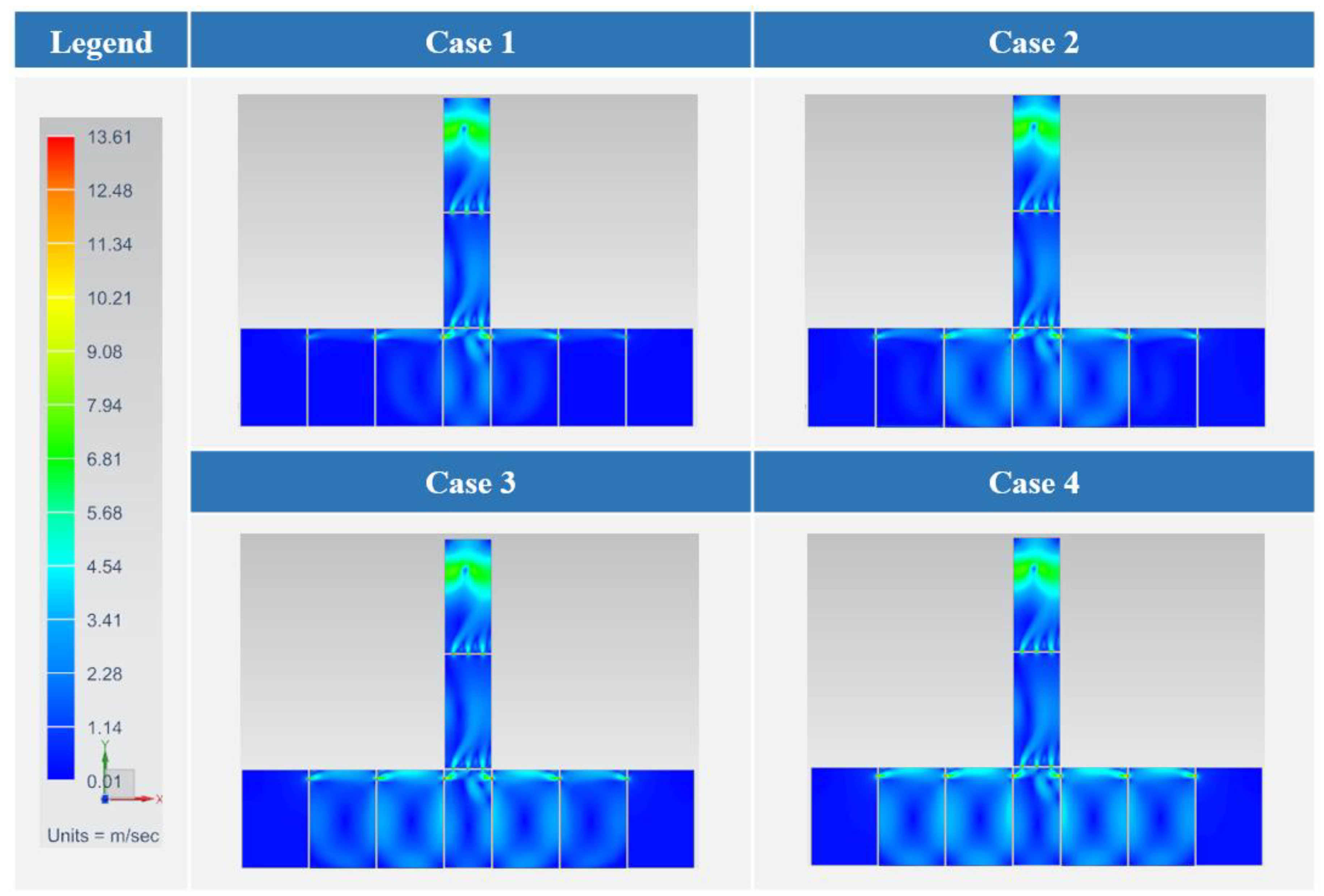
Figure 8 shows the distribution of the velocity inside the connected air-type BIPVT collector according to the opening ratio. The velocity in the collector was different for each of the four cases, and the air flow in case 4 was more uniform than those of the other cases.
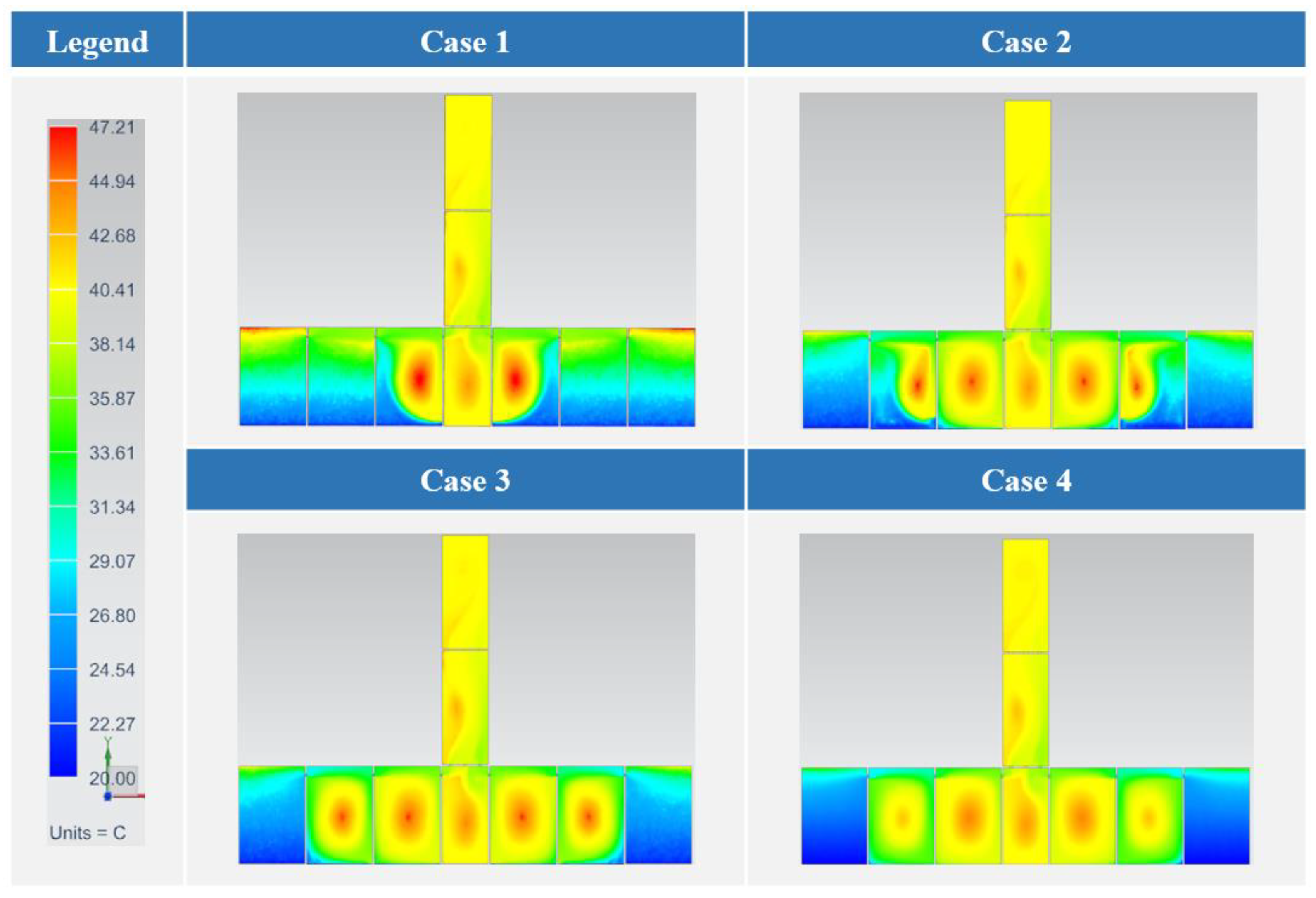
Accordingly, the temperature distributions within the collectors were different from each other, as shown in
Figure 9. In case 1, high temperatures were concentrated in the middle of the connected collector. On the other hand, in cases 2, 3, and 4, as the air inflow increased in BIPVT 1 and 6, the portions where the central high-temperature was concentrated gradually become uniform. As it passed through the collector, air flowed more smoothly in case 4 than in case 1, and the air flow became longer.
Therefore, the inlet opening ratios of BIPVT 1 and 6 were fixed at 100%, and as the opening ratio of BIPVTs 2, 3, 4, and 5 decreased, the air inflow of each BIPVT collector increased and the air flow became smooth.
Figure 10 is a graph showing the inlet velocity according to inlet opening ratio. In case 1, for all BIPVTs with the same inlet opening ratio of 100%, the inlet velocity slowed to 0.0113–0.214 m/s. The inlet velocities of cases 2, 3, and 4 were higher than that of case 1; especially, the inlet velocities of BIPVT 3 and 4 were higher than those of the other inlets. Case 4 shows that the flow velocities (about 3.8 m/s) of BIPVT 3 and 4 (opening ratio 5%) were higher than those of the other cases. This was because the inlet velocity increased as the inlet opening ratio decreased for the flow (500 m
3/h) discharged to the outlet.
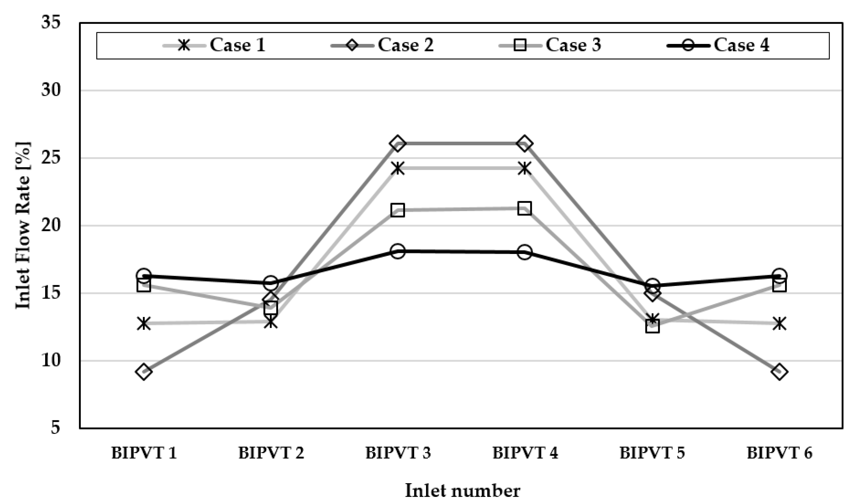
Figure 11 is a graph showing the inlet flow rate distribution according to the opening ratio. In cases 1 and 2, the inlet flow rates of BIPVT 3 and 4 were two times higher than those of the other inlets. On the other hand, case 4 had more uniform flow distribution than the other cases. Therefore, it was thought that BIPVT 3 and 4 should have small opening ratios and high flow rates in order to maintain uniform air inflow amount for each BIPVT collector.
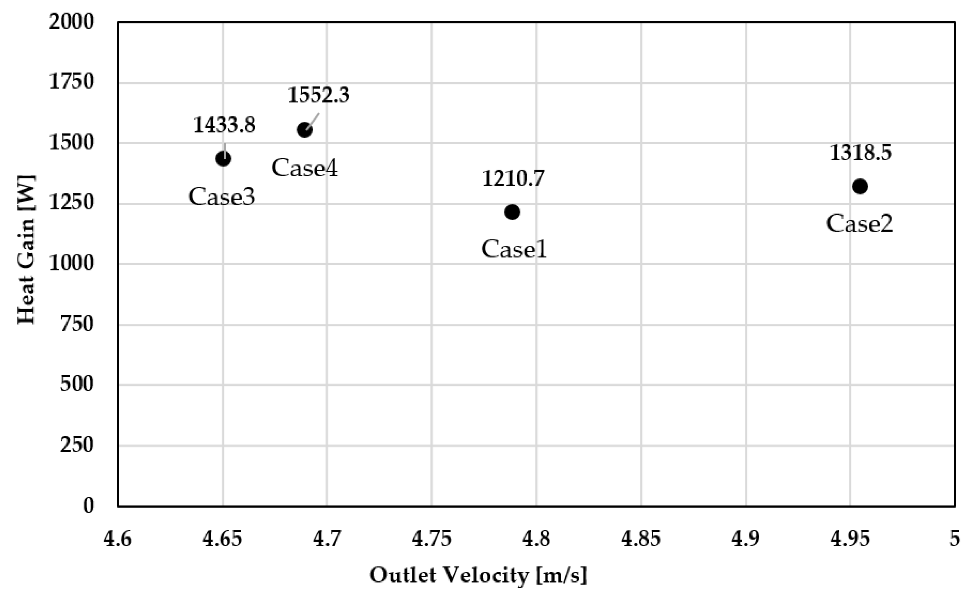
Figure 12 is a graph of the heat gain according to the outlet velocity. When the flow velocity of the air-type PVT collector’s outlet is high, air flowing inside the collector passes through with little heat gain. The outlet velocities of cases 3 and 4 were 4.65 m/s and 4.69 m/s, respectively, which were relatively slow. Accordingly, the heat gains of Cases 3 and 4 were high at 1433.8 W and 1552.3 W, respectively.
Therefore, the flow velocity and temperature distribution in the BIPVT 1–6 collector for case 4 were relatively uniform. In addition, each inlet flow rate of BIPVT 1–6 was uniformly supplied and the amount of heat gained by air passing through the collector was confirmed to be high. As a result, it was thought that the BIPVT collector performance in case 4 was relatively favorable in terms of heat transfer.
2.4.2. Pressure Drop and Thermal Efficiency
The pressure drop inside the air-type BIPVT collector is as important as the heat transfer performance because it is related to the blowing (fan) power. As the pressure drop in the collector increases, the power required for flow increases and the heat transfer performance decreases. The Reynolds number is the ratio of the force due to inertia to the force due to viscosity (Equation (1)) and is a factor determining laminar flow and turbulence. If the Reynolds number is high, the flow is classified as turbulent. The characteristics of this flow (turbulent flow) are fast and turbulent, such as when a vortex occurs. Thus, the heat transfer and heat diffusion effects in the BIPVT collector are strong.
: Density of the fluid (kg/m
3);
V: Average velocity of the air (m/s);
L: Characteristic linear dimension (m);
: Dynamic viscosity of the fluid (kg/ms); and
: Kinematic viscosity of the fluid (m
2/s).
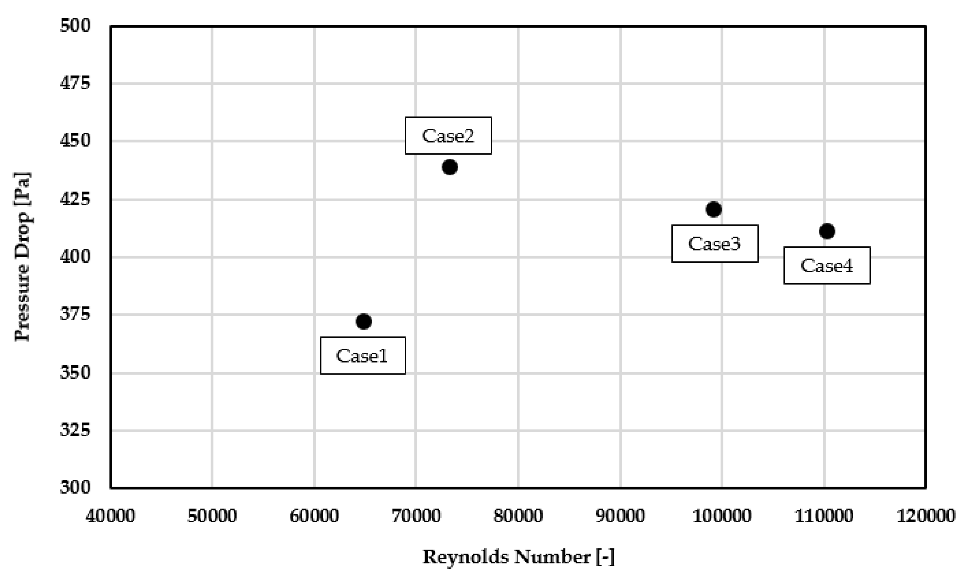
Figure 13 is a graph showing the pressure drop in a pneumatic BIPVT collector according to the Reynolds number. The pressure drop was the lowest in case 1 (372 Pa); order of case 4, case 3, and case 2 was shown.
The Reynolds numbers of all cases were the turbulence values; case 4 had the largest value of 110,400. It was found that for the larger BIPVT inlet opening ratios in case 3, case 2, and case 1, the Reynolds numbers were smaller. Therefore, the heat transfer performances of the case 3 and 4 collectors with large Reynolds numbers and relatively low-pressure drops were more favorable.
Generally, the thermal efficiency of air-type BIPVT collector can be calculated using Equation (2).
Table 3 shows the thermal efficiency of the air-type BIPVT collectors. The inlet/outlet temperatures of the collectors were obtained by simulation. Based on this analysis, the thermal efficiency of the air-type PVT collector was found to be highest in case 4 (39.5%), approximately 20% higher than that in case 1.
In case 1, a lot of air was introduced into BIPVT collectors 3 and 4 while, in case 4, the amount of air flowing in each inlet was uniform. This leads to an increase in the outlet temperature of the connected BIPVT because the flow path, which can be preheated, becomes longer as more of the externally introduced air passes through each of the collectors. Consequently, it was found that the thermal efficiency of case 4 was the highest. It was confirmed that a smaller opening ratio of the inlet near the outlet led to higher thermal performance of the air-type BIPVT collector.
ABIPVT: Surface area of the collector (m
2);
G: Solar radiation (W/m
2);
: Mass flow rate (kg/h);
Cp: Specific heat of air at a constant pressure (J/kg °C);
Toutlet: Outlet air temperature of BIPVT (°C);
Tinlet: Inlet air temperature of BIPVT (°C); and
: Thermal efficiency (–).
3. Analysis of Experiment Results
The meteorological data elements measured for the demonstration experiment were vertical irradiation, outside temperature, outside humidity, wind direction, wind speed, and atmospheric pressure (
Table 4). A meteorological data measuring device was installed on the roof of the building, without shadows. To measure the performance of the air-type BIPVT collector, the cell temperature of the PV module, the outlet temperature, and the humidity of the BIPVT collector were measured. A flowmeter, thermo/humidity meter at the outlet of the BIPVT collector was installed in the duct, and a T-type thermocouple sensor to measure the cell temperature was attached to the back of the PV module.
Based on the simulation results, the performance of the air-type BIPVT collector applied to the south side facade of the demonstration building was analyzed.
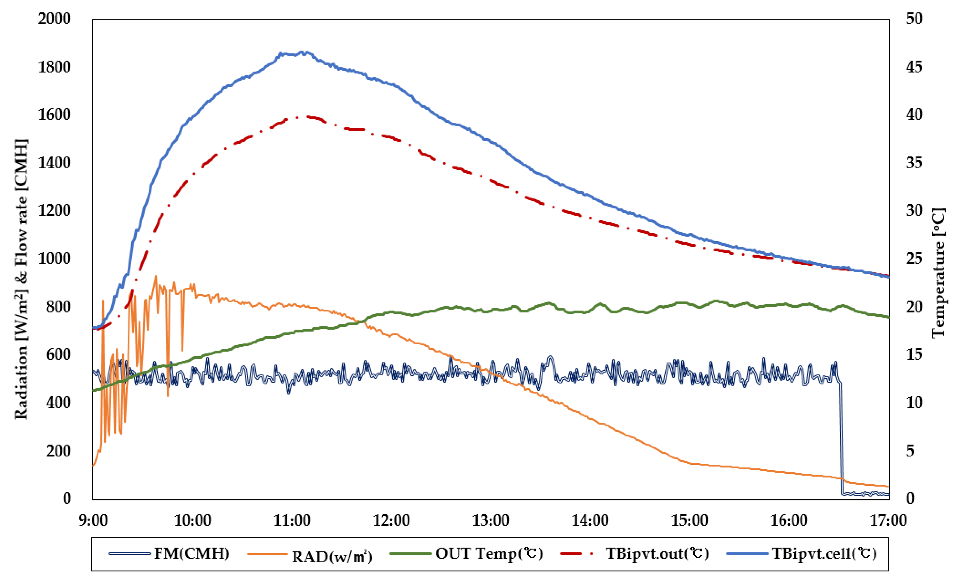
Figure 14 is a graph showing the ambient conditions of a clear day (22 March 2018) and the flow rate and cell temperature of the air-type BIPVT collector. Preheated air from the collector applied to the facade enters the building’s AHU (air handling unit) system. The flow rate of the collector was kept at 500 m
3/h when the AHU system fan was operated.
In the experiment, it was found that the outside temperature was up to 20 °C, and this outdoor air flowed into the collector inlet. The cell temperature at the back of the PV module of the connected collector rose to a maximum of 47 °C, and the outlet temperature of the air-type BIPVT rose to a maximum of 40 °C. The backside cell temperature of the PV module and the outlet temperature of collector were also similar to the solar radiation trend. Outside air at 17–18 °C flowed into the collector inlet and preheated air with a temperature of 20 °C or higher was used in the AHU system, combined with the heat of the building; as such, the energy used in the building could be reduced.
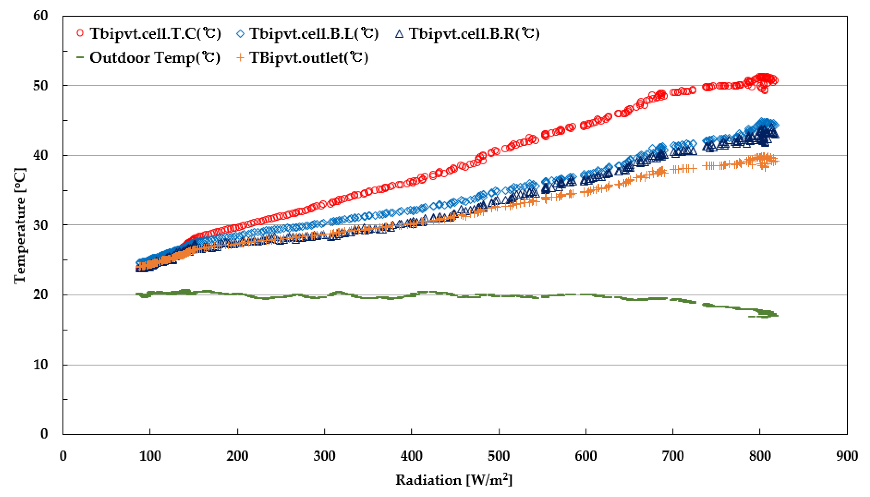
Figure 15 is a graph showing the temperature characteristics of the connected air-type BIPVT collectors. The temperature characteristics of the collector confirm the backside temperature of the PV module and the temperature difference between the inlet and outlet of the collector. First, the temperature of the backside of the PV module was measured at two bottom points and at one top center point of the connected collector (
Figure 6); the temperature of the backside of the module increased as the solar radiation increased. The temperature of the upper PV module of the collector was also consistently about 7 °C higher than the temperature of the lower module. Next, the inlet/outlet temperature difference of the collector was found to increase with the increase of the irradiation amount and reached 20 °C or more.
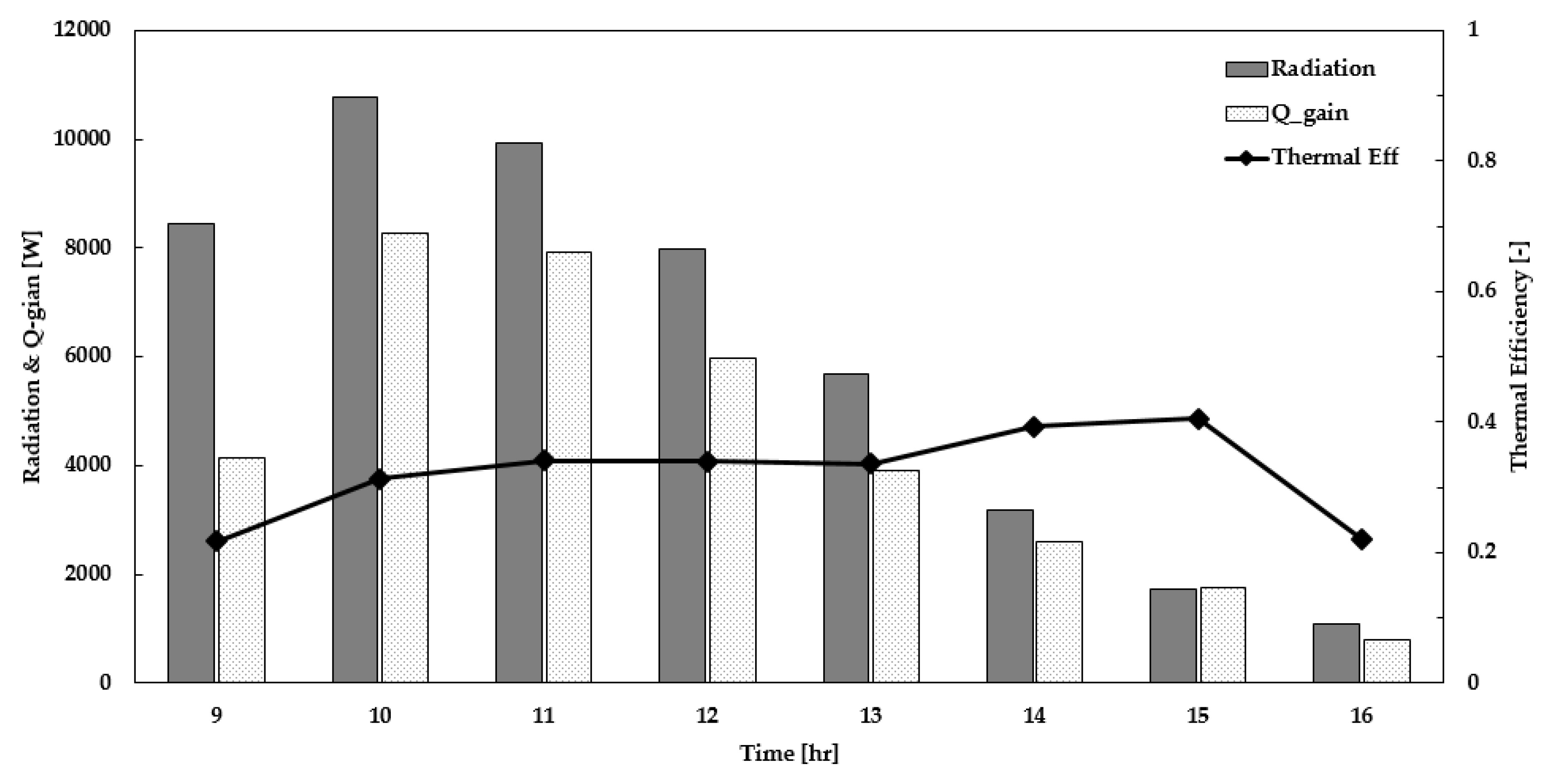
Figure 16 is a graph showing the daily hourly thermal performance of the air-type BIPVT collector. The amount of solar radiation per day was 650–800 W/m
2; the amount of solar radiation input into the collector was an average of 6 kW/h. As a result, the thermal energy produced by the BIPVT collector was an average of 4.4 kW/h. The thermal efficiency of the coupled air-type BIPVT collector was calculated by substituting the actual measured solar irradiance and the collector inlet/outlet temperature difference into Equation (2). The thermal efficiency on the day of the experiment was analyzed and found to be 33.4% on the average; this value showed a difference of about 6%
p from the simulation result of 39.5%.
4. Conclusions
An air-type BIPVT collector is important to keep air flow inside the collector uniform to obtain a high-temperature air heat source. In this study, the inlet opening ratio of the collector was adjusted for smooth and long air flow through connected several collectors; the air flow characteristics inside the collector were analyzed through CFD simulation.
As a result of the simulation analysis, it was found that the temperature and flow velocity distribution became smooth as the opening ratio of the air-type BIPVT collector became smaller in terms of heat transfer; also, the flow distribution of air flowing into the inlet became uniform. Accordingly, the thermal efficiency of case 4 was 20% higher than that of case 1. Based on the analysis of the CFD results, case 4, which had the most favorable air flow, was applied to the demonstration. As a result, the temperature difference between inlet and outlet of the connected BIPVT collector showed values of up to 20 °C or more; average thermal energy produced per hour was 4.4 kW (thermal efficiency was approximately 33.4%).
When installing an air-type BIPVT collector according to the design of the building facade, the internal path and the connecting method of the inlet/outlet with collectors should be considered. The collector airflow should be designed to flow uniformly. In the future, based on demonstration experiment results, it will be necessary to analyze the energy performance of the AHU system using an air heat source from an air-type BIPVT collector.


