Article

Design of Cable Termination for AC Breakdown Voltage Tests †

by
Arthur F. Andrade
1,*,
Edson G. Costa
2,
Filipe L.M. Andrade
1,
Clarice S.H. Soares
1 and
George R.S. Lira
2
1
Center of Electrical Engineering and Informatics, Federal University of Campina Grande, Campina Grande 58429900, Brazil
2
Department of Electrical Engineering, Federal University of Campina Grande, Campina Grande 58429900, Brazil
*
Author to whom correspondence should be addressed.
This paper is an extended version of our paper published in 2018 IEEE International Conference on High Voltage Engineering and Application (ICHVE 2018), Athens, Greece, 10–13 September 2018; pp. 1–4.
Energies 2019, 12(16), 3075; https://doi.org/10.3390/en12163075
Submission received: 3 July 2019 / Revised: 29 July 2019 / Accepted: 30 July 2019 / Published: 9 August 2019

Abstract

:
International standards prescribe overvoltage tests to evaluate the insulating material performance of high-voltage cables. However, it is difficult to manage the electric fields at the cable ends when laboratory measurements are carried out because surface and external discharges occur at the cable termination. Therefore, this paper presents a procedure for designing cable terminations to reduce the electric field at the cable ends to appropriate levels even in the case of overvoltage tests. For this purpose, computer simulations of electric field distribution using the finite element method (FEM) were performed. A 35 kV cable model was employed as a sample. An voltage with RMS (root mean square) value of 300 kV was used as an overestimate of breakdown voltage for the internal insulating material. The cable termination model obtained through the proposed methodology allows an electric field reduction in air, preventing the occurrence of external discharges, and thus permitting the breakdown voltage measurement of the cable’s inner insulation.

1. Introduction

In engineering, an ideal solution or project must be established due to economic, technical, practical, and environmental limitations. In the design and construction of power transmission or distribution lines, two types of cable can be used, namely overhead or underground cables [1]. High-voltage underground cables have been widely used as electrical conductors in different applications such as medium-voltage industrial facilities, underground and submarine transmission connections, renewable energy plants [1], the feeding of residential buildings and urban centers, as well as in facilities where environmental and visual aspects require the use of underground cables. However, the installation of underground cables represents a significant financial expenditure when compared with the application of overhead cables [1,2].
In addition, the complex manufacturing process of underground cables and the diversity of products and manufacturers can lead to the commercialization of low-performance cables. The use of good performance cables is essential for underground applications, since the cables are subjected to several stresses during their lifetime, such as electrical (due to operation voltages, overvoltage surges, and others), thermal (since the cables are subjected to abnormal temperature rises, thermal expansion, and contraction), mechanical (such as external damages, lateral impact, and pressure abnormalities), and environmental (due to humidity, oxidation, solar radiation, and other phenomena) [1].
Therefore, in order to ensure operation under the aforementioned stresses and improve the power supply reliability and continuity, cables must be exposed to routine and type electrical tests to guarantee, essentially, the dielectric performance of the insulation material and reduce, consequently, the financial losses for power utilities and industries. One of the most widely used materials is cross-linked polyethylene (XLPE) [2,3,4,5].
Although most failures in a power cable occur at its junctions and terminations, the evaluation of the cable insulation material is extremely necessary. One of the tests required for this evaluation is the cable breakdown voltage determination. International standards IEC 60229 and IEC 60520-2 [6,7] establish the test requirements for high-voltage cables. In Brazil, the standards NBR 10299 and NBR 16132 [8,9] provide the specifications in regard to the tests for the statistical distribution of puncture electric field strength in cables for systems with a voltage above 15 kV. NBR 10299 aims to set the minimum failure rate based on the installed cable length. A generally accepted value is 6.7 × 10⁻⁴ failure/(year × km) [8].
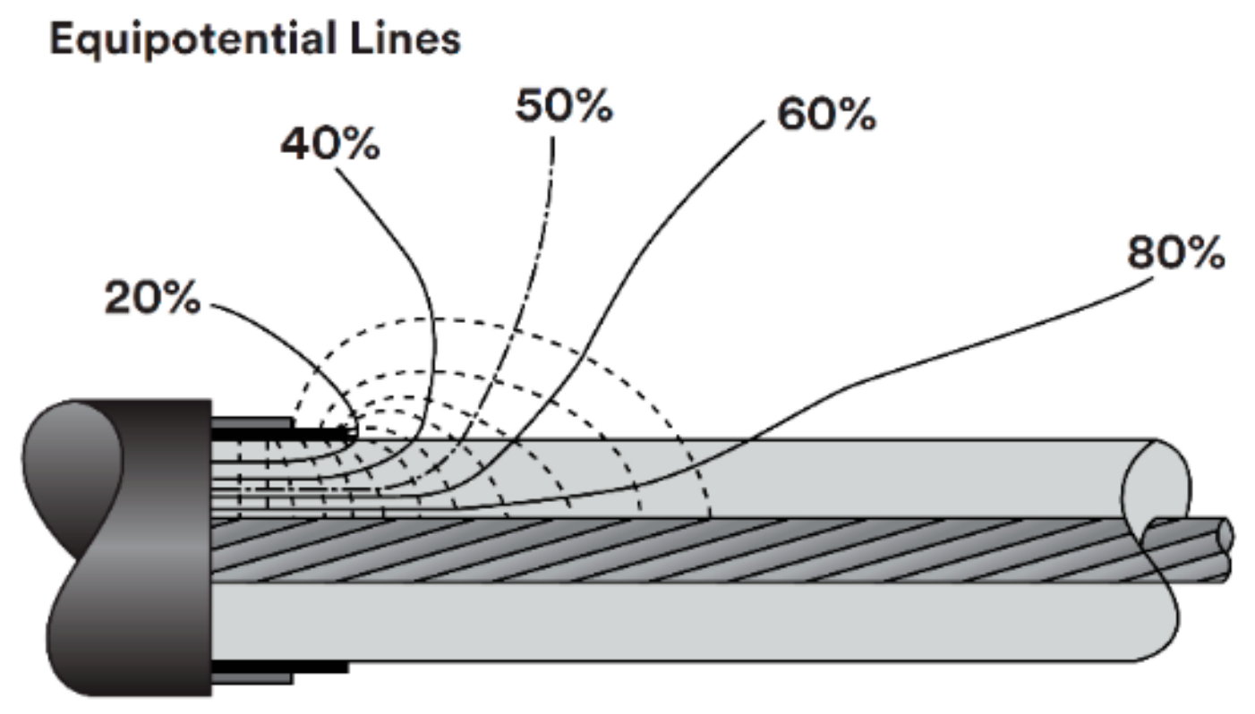
The prescribed tests should be performed using a sample of at least 3 m effective length, that is, without considering the terminations on both sides. The external shielding is grounded and a rising AC voltage is applied over the cable until the internal breakdown is reached. The experimental setup should ensure the breakdown occurrence on the effective length cable. Considering that the tests can subject the cable to overvoltages with values of 5 to 10 times greater than the normal operation voltage, the main problem faced during the tests is the electric field distortion at the cable ends, which causes external rupture and prevents the evaluation of the inner insulating material.
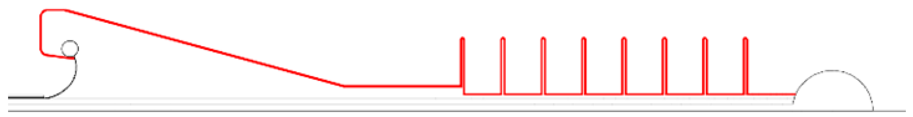
To carry out the installation in field or breakdown voltage tests in insulated cables, it is necessary to remove a part of the cable insulation. While the electric field inside the effective length has a predictable distribution, with a radial direction and logarithmical behavior [1,2,10], there is a great field intensification at the cable ends. The electric field in the vicinity of the shield end is illustrated in Figure 1. Thus, such a predictable distribution should be guaranteed to allow successful tests.
The cable end consists of a conductor, semiconductor layers, insulating layer, and conductive tape for the shielding, in addition to air. The diversity of materials with different electrical characteristics, dielectric strength, and relative permittivity provides highly non-uniform electric fields with both axial and tangential field components. The tangential electric field is one of the main reasons for failures in terminals [12,13]. The field enhancement at the cable end produces surface and external discharges in the air, which can be prevented by using properly designed terminations [1,9,10,14]. In this sense, arrangements with different characteristics were studied by [12,13,14,15,16,17,18,19].
Most of the studies that have dealt with the electric field distribution in high-voltage cable terminations apply commercial software based on the finite element method (FEM) for the purpose of analysis and/or design of terminations, joints, or stress relief cones. In [12,15,16], simulations were used to assist in the design of stress cones based on high-temperature superconductors (HTS). The authors of [16] proposed the use of an epoxy/ZnO conductive layer to improve the electric field distribution. Other studies compared different materials and field grading options for cables. In [13], for example, different types of field grading options for 36 kV paper-insulated lead cables (PILC) and cross-linked polyethylene (XLPE) cables were compared. In [17], the impact of defects on cable joints was analyzed, and [18] studied the electric field in a cable termination undergoing transient stresses. During the project stage of a termination, another possible objective is to estimate areas more susceptible to defects and thus improve prototypes. In this regard, [19] calculated the electric field in a sleeve for a 110 kV cable using FEM, in order to estimate zones more susceptible to dielectric breakdown and thus improve a sleeve prototype.
Some of the aforementioned studies presented termination projects based on the stress cone concept, and analyzed electric field distribution or the influence of different materials. However, there is a lack of studies related to termination performance during overvoltage tests or breakdown voltage tests. In addition, some proposed prototypes require expensive materials.
Therefore, a methodology for the conception, drawing, and electrostatic simulation of a feasible termination is reported in this paper. The termination must be able to ensure the completion of overvoltage tests on cables. The proposed procedure can also be used for the design of optimized cable terminations. Such terminations are usually responsible, for example, for the linking between different transmission lines, functioning as connectors. For the analyses of the electrical stresses at the termination, computational simulations were performed using a commercial software based on the finite element method and a single-phase 35 kV cable model, which was used as a sample. Conventional materials were considered in the project, which represents a potential cost reduction.

2. Materials and Methods

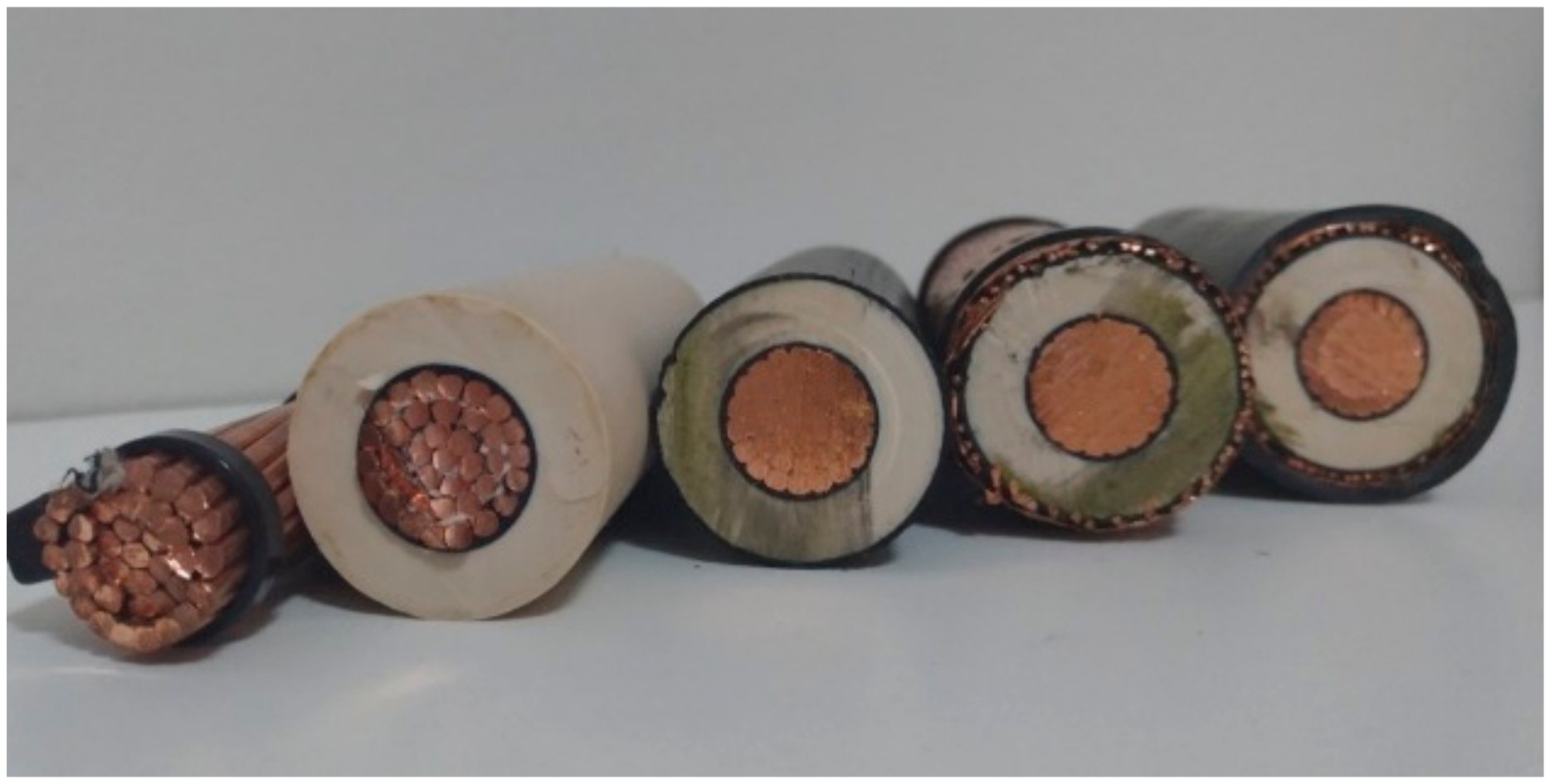
Sections of an XLPE 35 kV insulated cable designed for application in underground and underwater environments were used as design samples. As can be seen in Figure 2, the cable consists of a copper conductor suitable for the electric current conduction; a thin semiconductor layer for the reduction of electric field distortions; a thick layer of insulation material, the XLPE being used for electrical insulation; another semiconductor layer; a conductive layer applied for the shielding or uniformization of the electric field inside the cable; and, finally, a layer of insulating rubber for mechanical protection. The layers can be seen from the (right) outermost to the (left) innermost part.
Initially, 5 m wide cable sections were used as samples in the laboratory tests. The samples were composed of 3 m of intact cable and two bare ends on both sides. An AC voltage of 300 kV was applied to the high-voltage cable to perform a dielectric withstand test on the internal insulation material. Although several termination configurations were implemented, the breakdown occurred externally to the cable before it was possible to puncture the test portion, resulting in an incorrect application of the insulation material evaluation test.
In order to identify the cable termination points most susceptible to discharges and to design an optimized termination in which the electric field intensity in those points is minimal, the COMSOL Multiphysics® software (version 5.4, COMSOL AB, Stockholm, Sweden) was used to perform 2D axis-symmetric simulations of the cable terminations. This software implements FEM to solve electrostatic problems [20] through three main steps—geometry modeling, assignment of material properties to each part of the modeled geometry, and choice of a mathematical model to describe the phenomenon.
For the studies presented in this paper, the electrostatic physics module was used. Using this model, it is possible to solve an electrostatic problem using Gauss’s Law:
  ·   D   =   ρ
associated with the definition:
E   =   V
and the constitutive equation:
D   =   ε 0 ε r E .
In Equations (1)–(3), the electric displacement field (D) symbolizes the way in which the electric field (E) will affect the organization of electric charges in the surroundings. D (C/m2) and the electric field itself (V/m) represent the interaction between charged objects. In Equation (1), ρ represents the free electric charge density [20]. The operator nabla ( ) represents the vector differential operator.
By definition, ε0 is the permittivity of free space and its value is 8.8542 × 10⁻¹² F/m. εr represents the relative permittivity of the material. The relative permittivity values of the materials used in the simulations can be seen in Table 1.
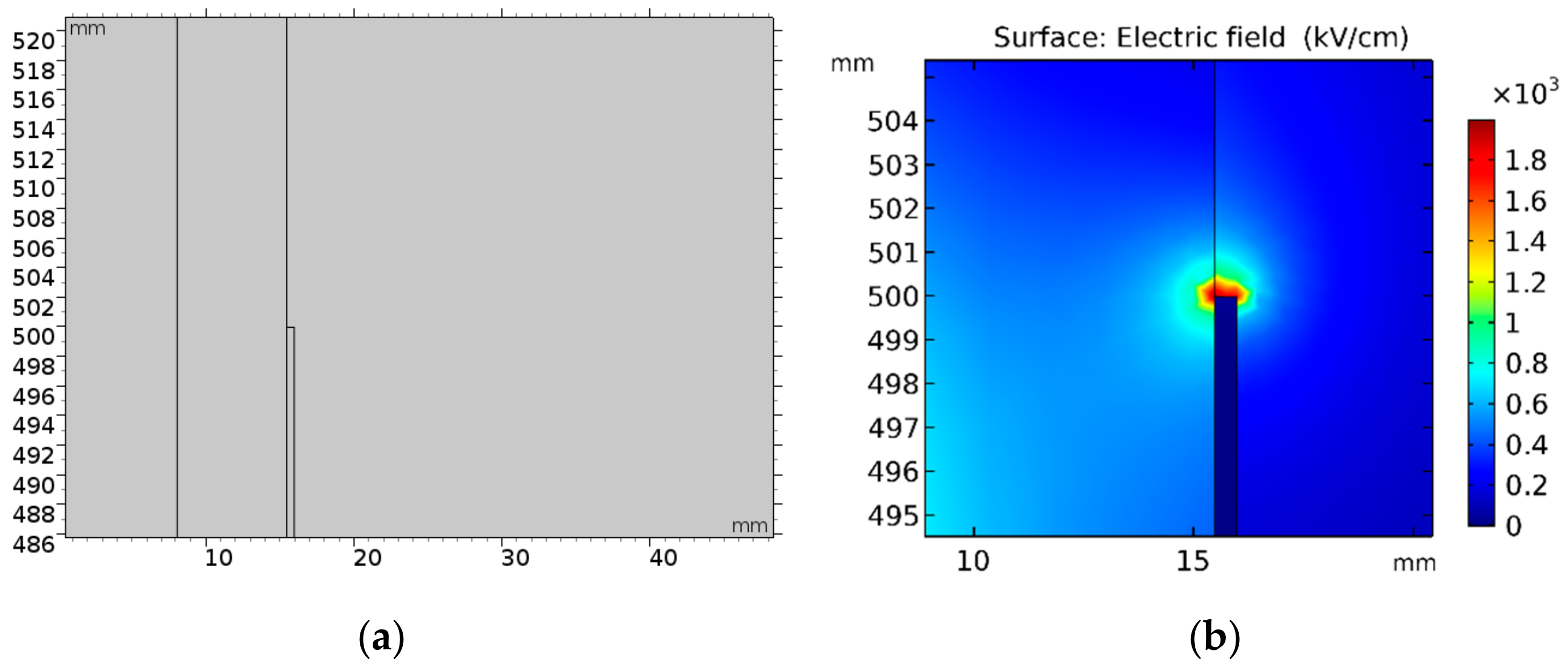
With the selected physics and material properties, the initial geometry of the cable termination that presented external discharges was modeled and simulated in order to identify the points where the electric field exceeded the breakdown’s stipulated limits for the air. Figure 3 shows that the intensification of the electric field occurred at the cable termination. Due to the high-intensity electric field at the external shielding end, it was necessary to build a termination model for the cable to accomplish successful overvoltage tests.
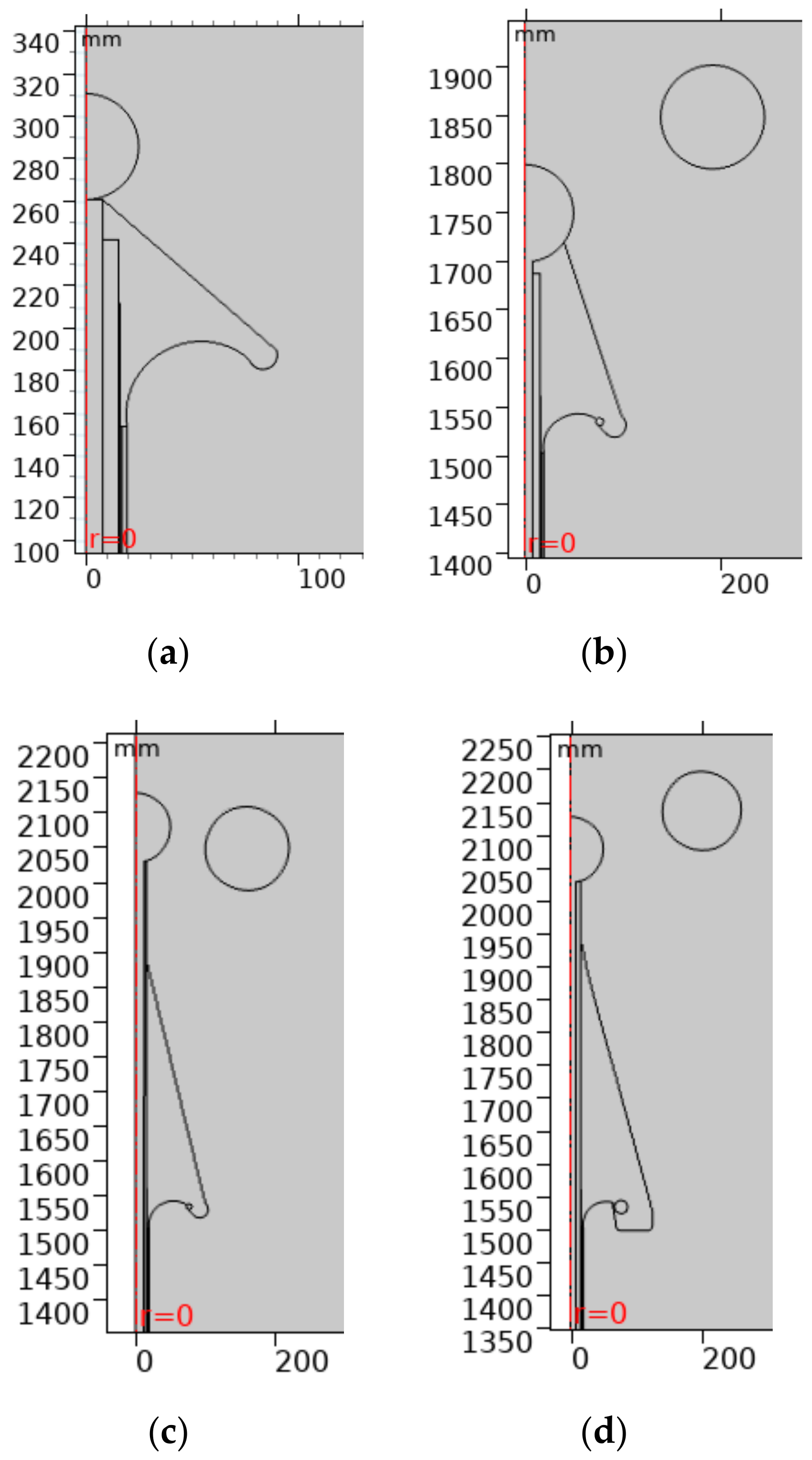
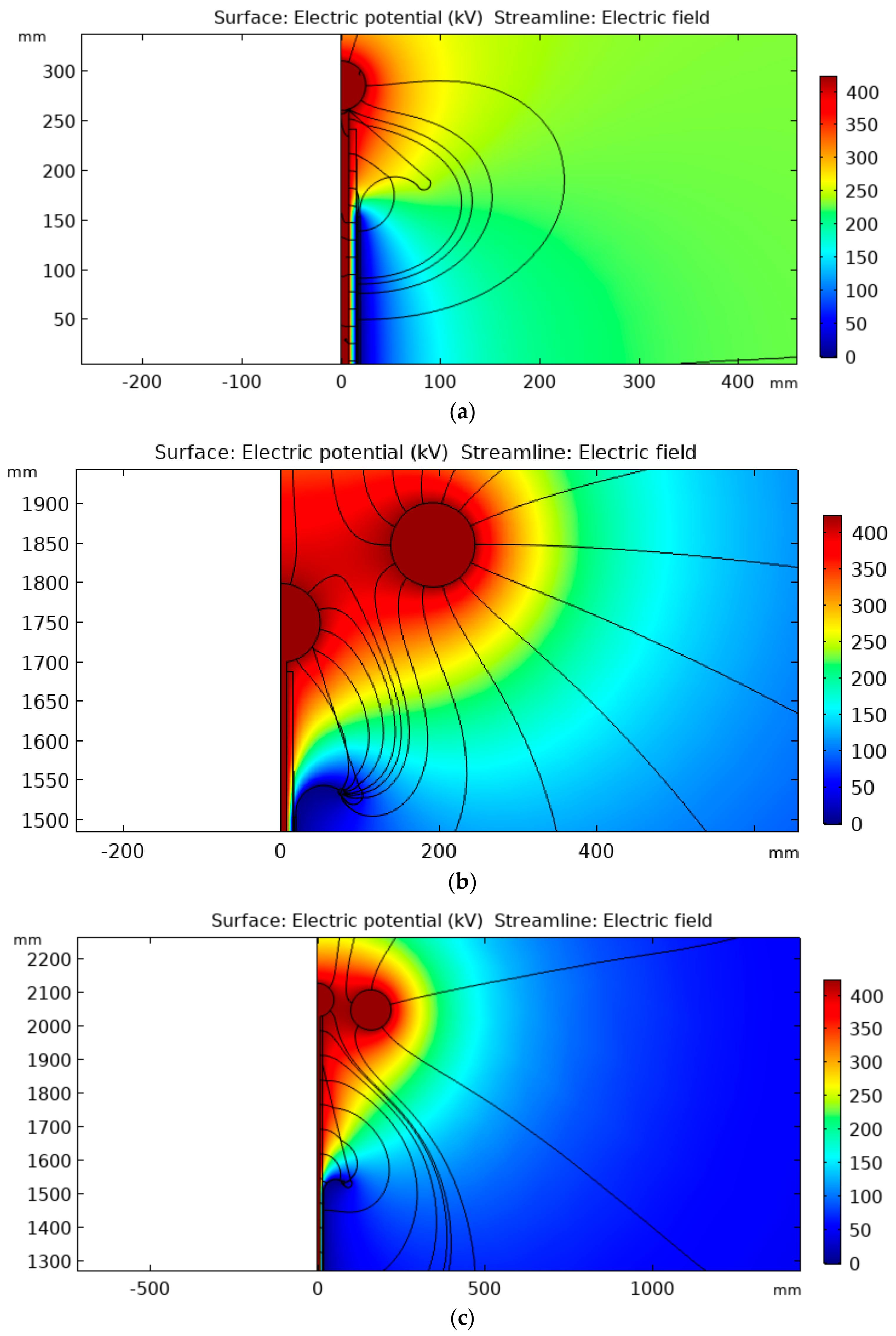
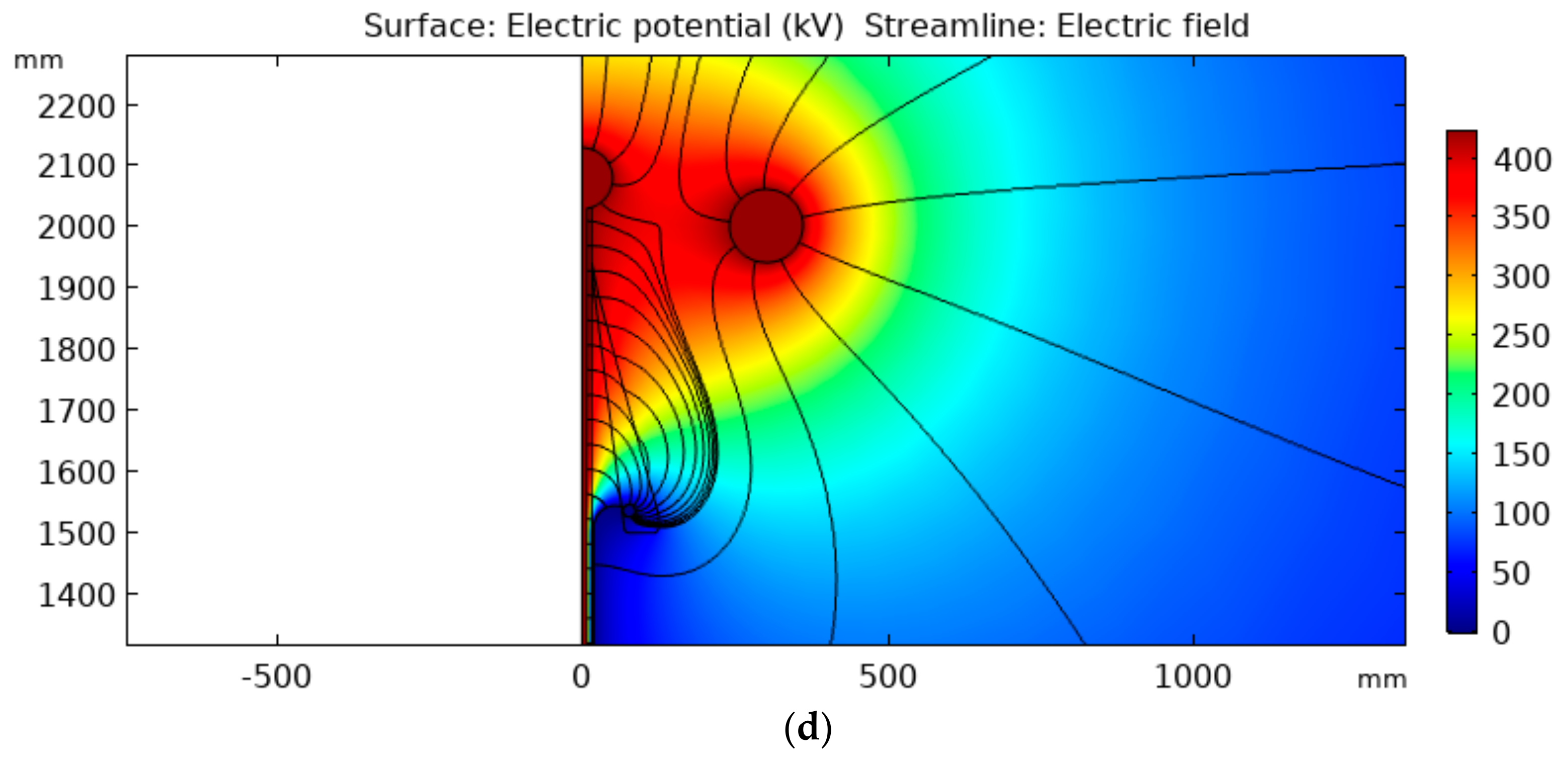
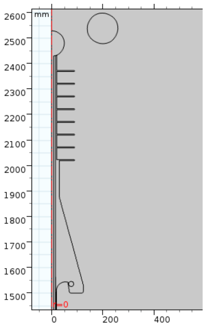
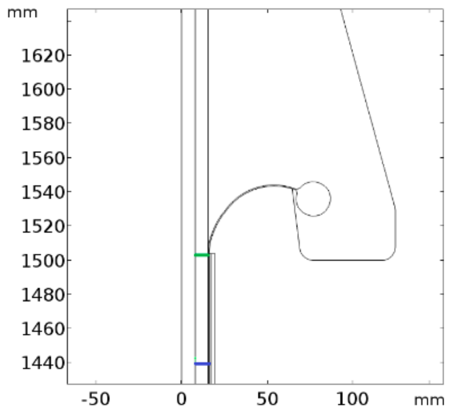
By applying the steps presented for preparing the simulation environment, we simulated successive cable termination geometries from the concept of the stress relief cone. Several models were created and tested until a final configuration was established. The main objectives of the simulations were to minimize the electric field near the cutting region of the semiconductor layer and in the air region between the termination and the high-voltage electrode, in order to minimize corona and reduce the possibility of discharges between the high-voltage electrode and the external grounded shield. Thus, in an overvoltage test, the insulation evaluated was guaranteed to be the internal one, since it was subjected to greater electrical stresses.
The simulation tests consisted of evaluating internal and external maximum electric field strength, as well the average electric field strength between the conductor terminal and the grounding end. In order to make a conservative estimation of the termination performance, a value of 424 kV was used as boundary condition for the applied potential on the simulations. This value corresponds to the peak value for a 300 kV RMS voltage. Due to the axisymmetric geometry, only a half longitudinal sectional view of the model was used in the analysis.

3. Results

In this section, the main termination designs created and analyzed during the test stage are presented, as well as the optimized final termination design. The performance of the prototypes was evaluated by the distribution and maximum value of the calculated electric field.

3.1. Intermediate Stages of the Termination Design

Initially, the main intermediate stages of the termination design are shown in Figure 4.
Successive improvements were made between the initial design step and the final step, aiming to improve the electric field distribution and reduce the maximum electric field on the termination surface and in the air region around the termination. The initial stress relief configuration is shown in Figure 4a. In Figure 4b, the shape of the stress relief cone was modified, having been elongated, and a conductive material with a metal ring for improving the field distribution was applied to the shield termination on the outer surface of the cone. A corona ring was also added to the high-voltage electrode. In the Figure 4c configuration, the cone length was increased, the geometry was improved, and the corona ring position was modified. In Figure 4d, the portion of the stress cone in which the external shield ends was modified again, and the position of the corona ring was optimized.
In Figure 5 and Figure 6, the potential distribution and maximum electric field around the termination are shown in the same order as the four intermediate stages presented in Figure 4.
As can be observed in Figure 5, a progressive change in the potential distribution was achieved due to modifications in the geometry. Moreover, as indicated in Figure 6, there was a progressive decrease of the maximum electric field in the air as the termination was being improved.

3.2. Final Termination Design

In the final version of the proposed termination, a rubber-composed stress relief cone and a termination electrode with a round end were designed. Near the cone, the termination also had rubber sheds to prevent the formation of a superficial discharge. At the end of the termination itself, a sphere-shaped corona ring was used for decreasing the electric field enhancement at the cable end.
A drawing of the final termination design is shown in Figure 7.
After the design definition, its dimensions were obtained, and an 2D-revolution form of the termination was drawn by using AutoCAD® computer-aided design software (2018 student version, AutoDesk, Inc., San Rafael, CA, USA). 3D drawing views of the designed termination are shown in Figure 8.
Similar to the results regarding the intermediate versions of the termination, the potential and electric field distribution obtained for the final version of the termination are shown in Figure 9.
From the streamlines in Figure 9, field intensification points can be observed. They are located on the stress relief cone and at the torus-shaped electrode. As can be seen in Figure 9b, the maximum electric field achieved its minimum value for the last configuration. In addition, unlike in the initial design stages, the point of maximum external electric field in the final design is not in the region between the high-voltage terminal and stress cone, but on the external shield, away from the region susceptible to breakdown. This fact results in a better performance of the termination. In Table 2, the maximum electric field calculated for each of the presented termination designs are presented and compared.
The results shown hereafter refer to the final termination design. The obtained result for the inner electric field on the termination is presented in the color plot in Figure 10.
As shown in Figure 10, the maximum electric field is of the order of 800 kV/cm, exhibiting a reduction in the maximum electric field of 2.25 times when compared to the preliminary computer simulations shown in Figure 3.
As a way to verify the electric field distribution on the XLPE dielectric, the electric field was investigated over two paths of the insulation material. These paths are shown in Figure 11.
In Figure 12, the distribution of the electric field over the points of Figure 11 is presented. Figure 12 curves represent the electric field decay along the insulating material radius. It is expected that a discharge must begin from a point where the field intensification is maximum. According to the standards, this point shall be inside the effective length of the cable, far enough from the external shield end.
Figure 12 curves show that the maximum electric field occurs on the blue curve, inside the effective length of the cable, even though it is also observed that both curves are close. In addition, as shown in the figure, the maximum field in the XLPE decreases with radius, thus indicating that breakdown will begin next the conductor surface and occur inside the effective length.
In Figure 13, the reduction of the maximum electric field along the cable length is shown considering a line adjacent to the inner conductor. The electric field intensity starts decreasing at the point where the external shield ends, which occurs at about 1504 mm.
In order to check the termination performance against superficial discharges as well as corona and arc formation, the electric field at the rubber termination surface was analyzed. Therefore, the defined path is the one exhibited as a red line in Figure 14, which unites high-voltage and zero potentials.
The electric field strength along the red line highlighted in Figure 11 can be seen in Figure 15. The length count starts from the termination electrode and ends at the surface of the high-voltage electrode.
The maximum electric field strength obtained on the termination surface was about 19 kV/cm near the stress relief cone. The effect of the insulating sheds can also be observed. The mean electric field throughout the superficial path is about 8.8 kV/cm.

4. Summary and Conclusions

The main contribution of this work is the proposition of a methodology that allows the design of adequate terminations that can withstand voltage tests and breakdown voltage tests in cables. Therefore, it was necessary to develop a termination that guaranteed that the greater electrical stress was applied to the internal insulation.
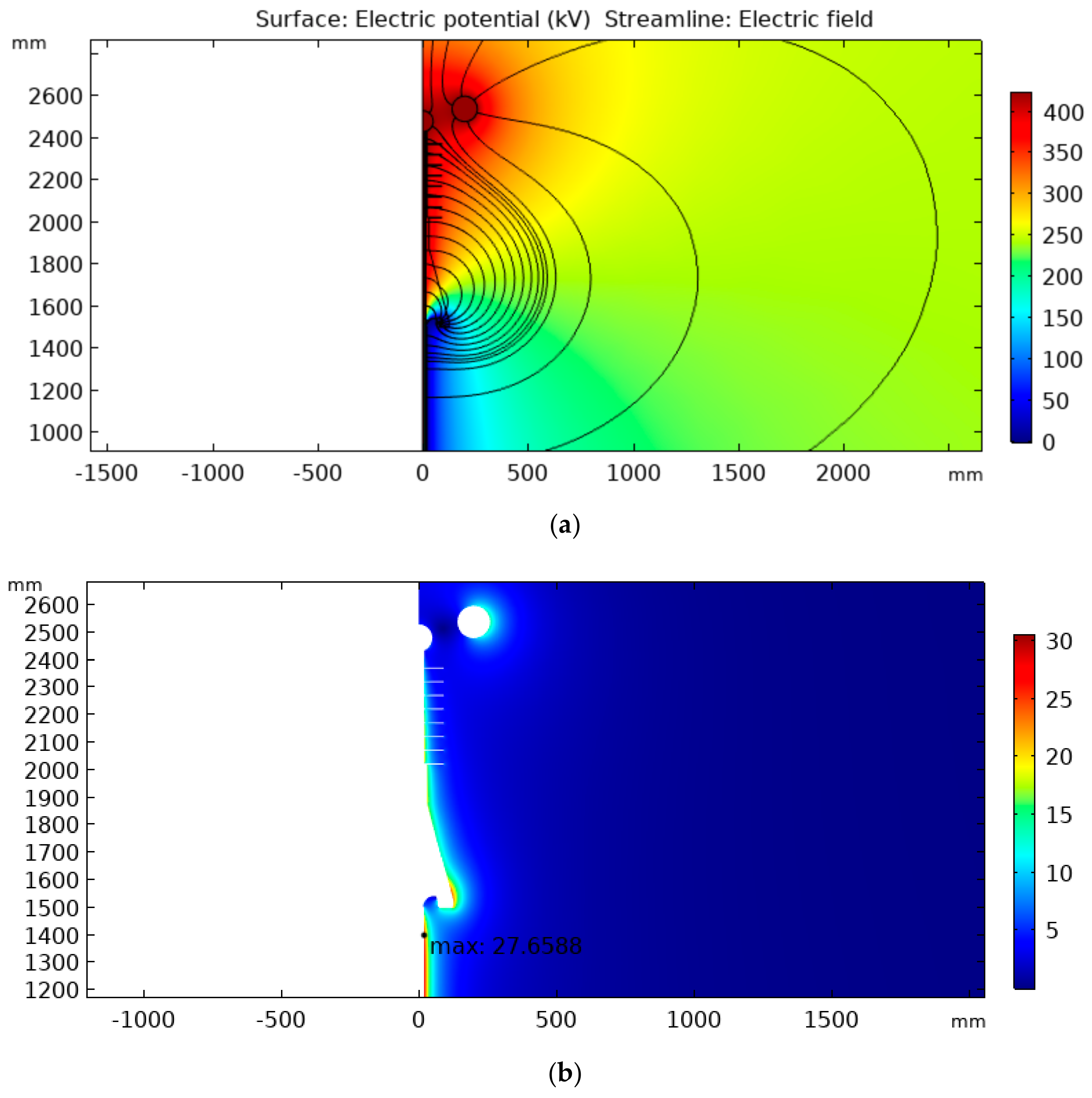
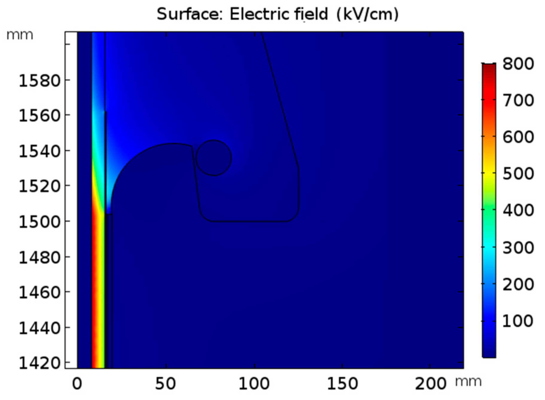
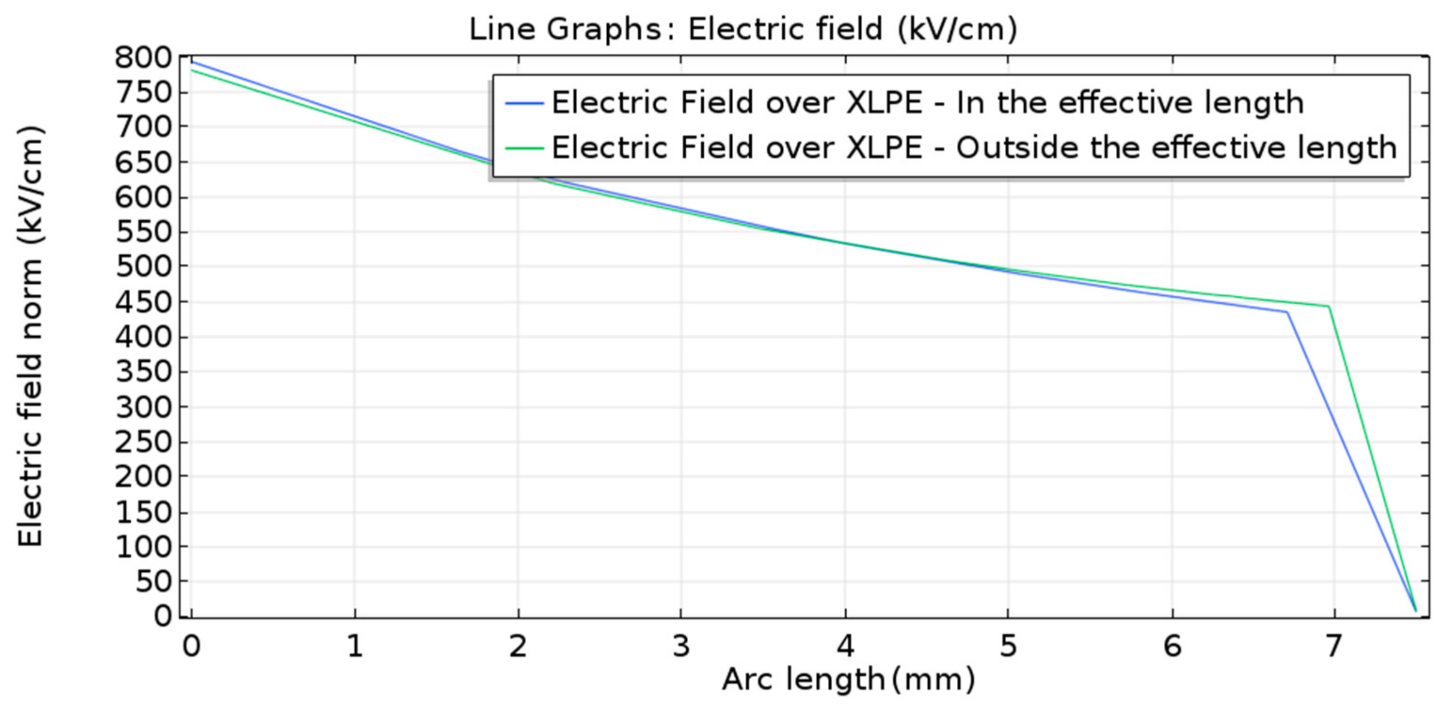
The optimized cable termination ensured that the electric field presented a greater probability of electrical breakdown inside the cable, in the cable part represented by the 3 m effective length. The achieved termination model minimized the probability of surface discharges and electrical breakdown between the high-voltage electrode and the external ground. In this context, the electric field distribution in the air and termination surface was also analyzed. As shown in Figure 15, the proposed termination allows the control of the surface electric field.
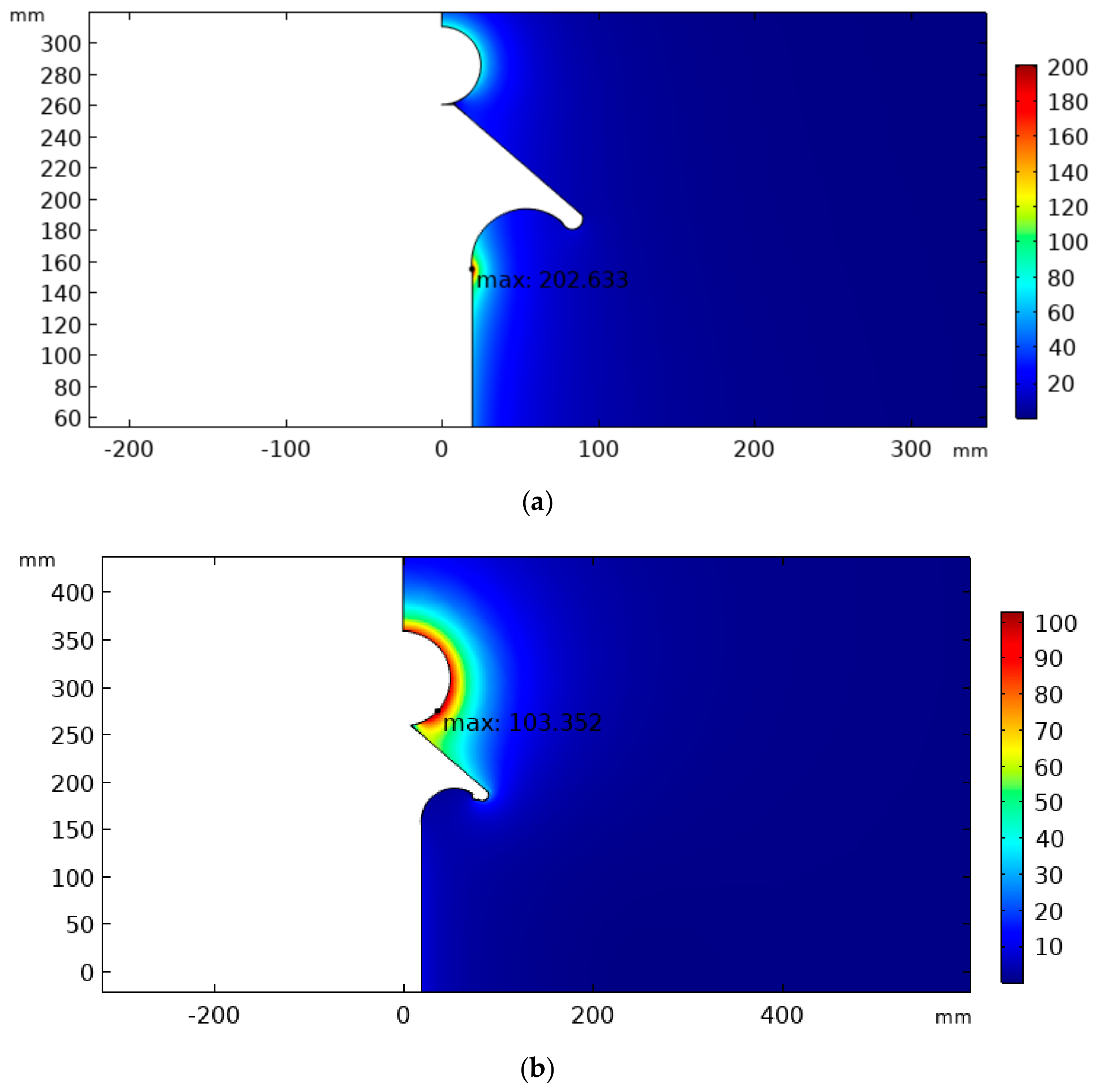
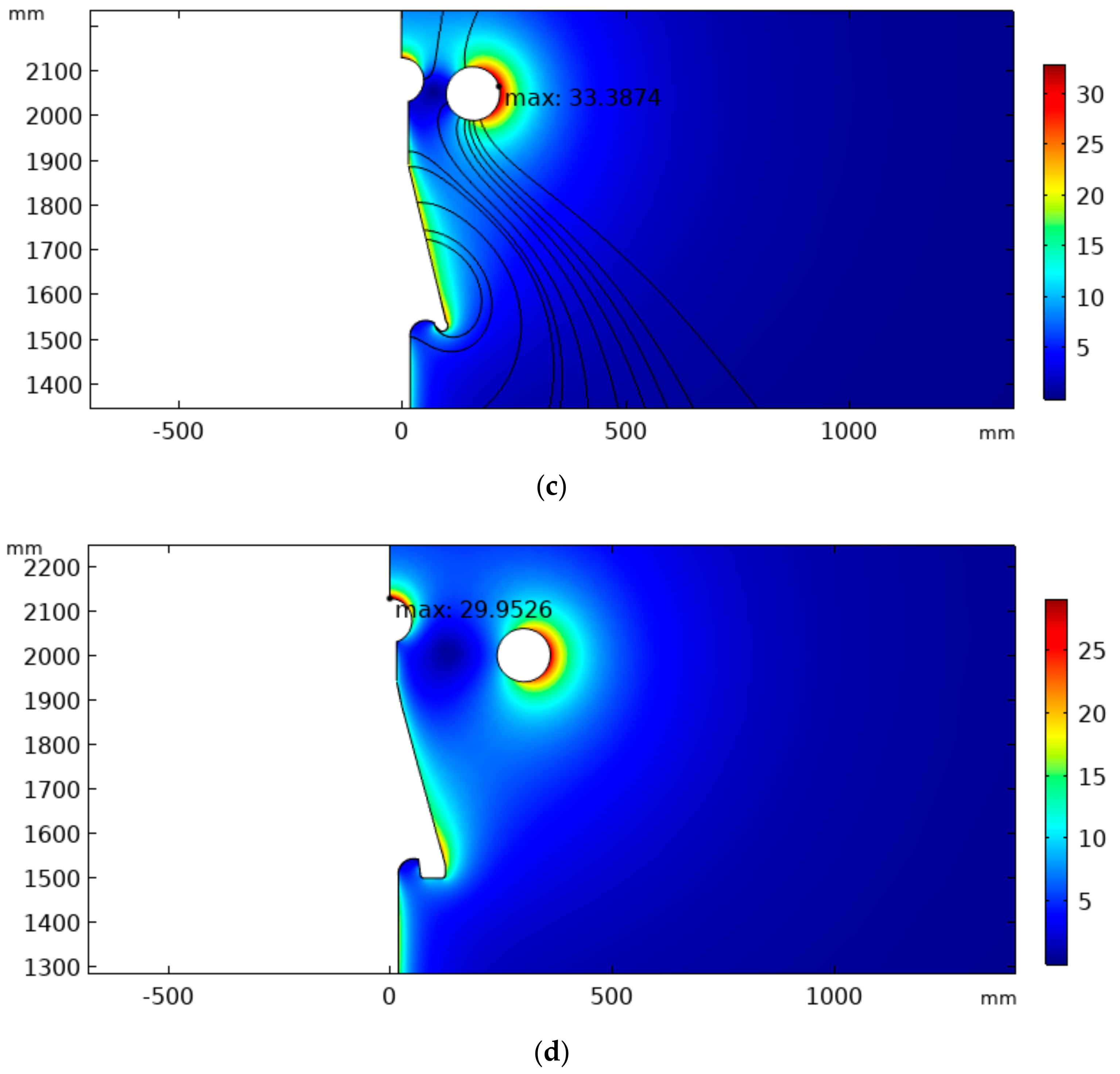
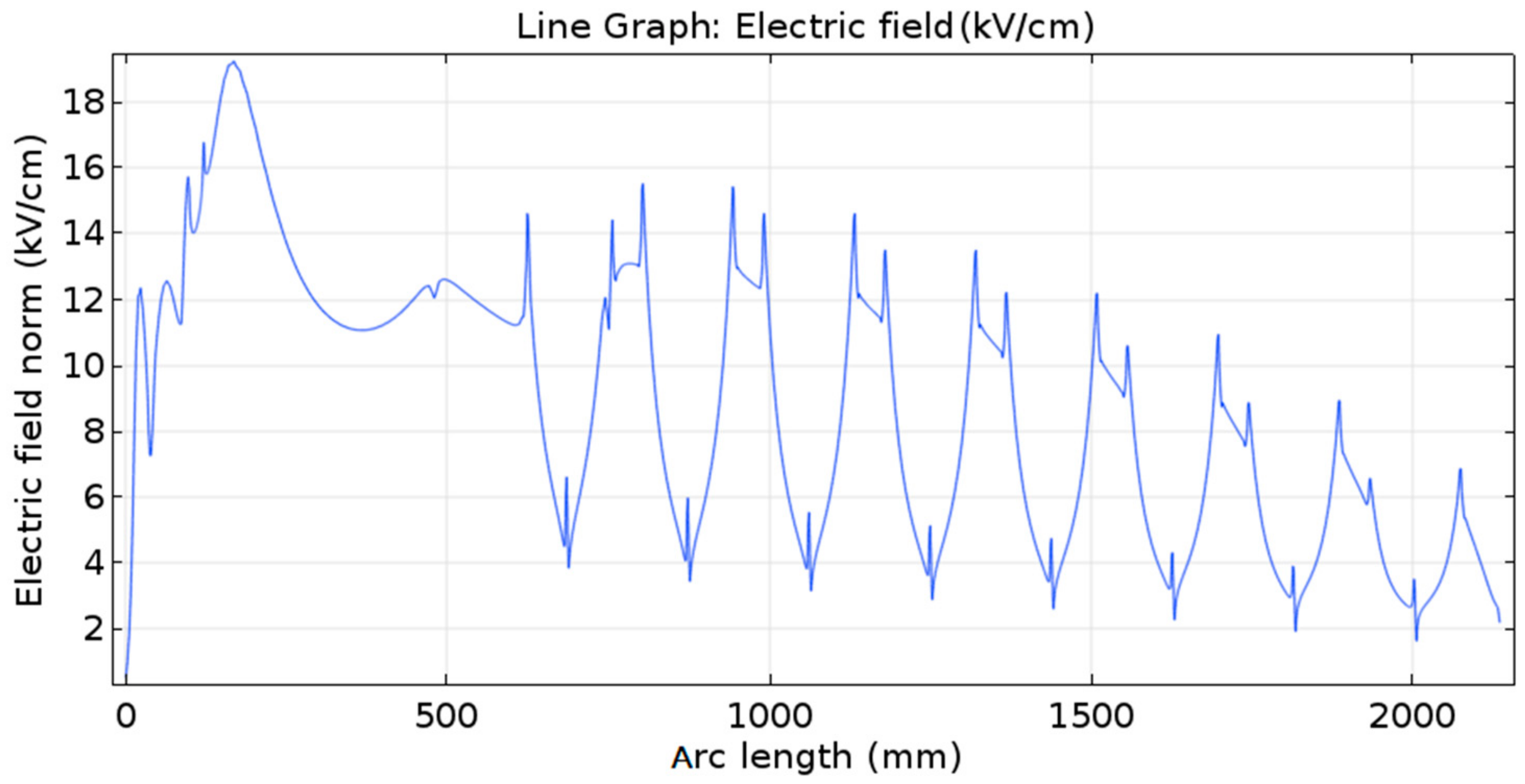
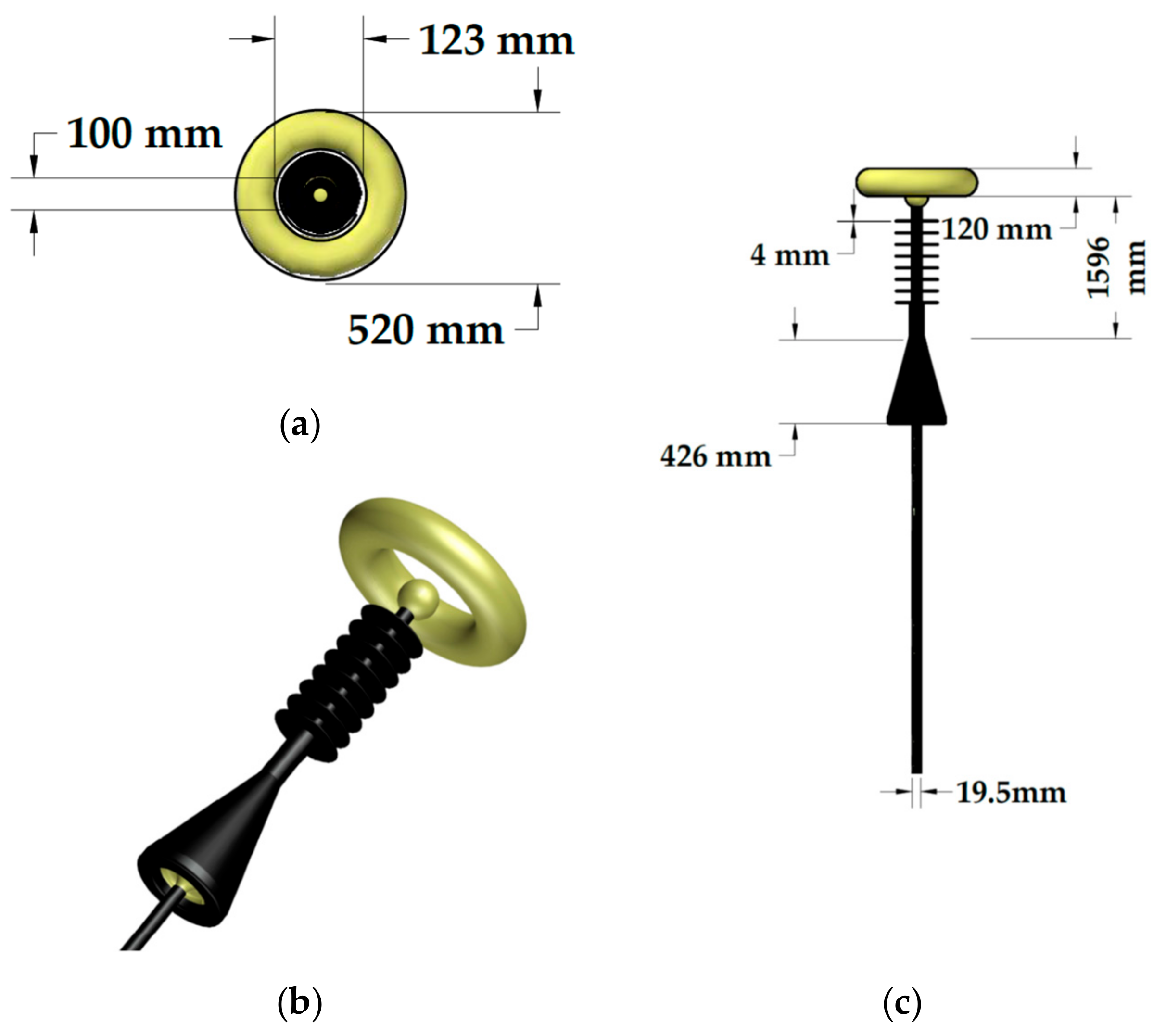
The proposed methodology was tested using a 35 kV XLPE cable model. The designed termination model contained an additional insulator to avoid tangential discharges and increase creepage distance, a metal sphere at the end of the structure, and a ring-shaped electrode to improve the electric field distribution in the surrounding air. As a result, the average electric field throughout the superficial path was about 8.8 kV/cm, and the maximum electric field strength was about 19 kV/cm, near the stress relief cone surface.
From the analysis of the results obtained in the simulations, it was observed that the objective was reached, given that, when applying the termination created, dielectric breakdown is more likely to occur in the effective length (inner part) of the cable. The performed simulations showed that a termination with the proposed dimensions and materials decreased the probability of electrical discharge at the terminations of the cable to be tested. The proposed termination eliminated the field intensification at the termination of the cable.
The proposed methodology benefits from advanced simulations to perform initial tests and to avoid wasting resources with unsatisfactory termination models. A termination was effectively developed for the cable considered so that overvoltage tests could be performed. Furthermore, conventional materials were considered in the proposed design, which represents a potential cost reduction. Future research may be carried out by developing new models in search of an improved result. The proposed termination should be built to carry out experimental tests in relation to its functionality. This study may also contribute as a basis for future studies in the HVDC area, especially the ones related to cable terminations.

Author Contributions

Conceptualization, E.G.C., F.L.M.A., and A.F.A.; methodology, C.S.H.S.; software, F.L.M.A., A.F.A. and C.S.H.S.; formal analysis, F.L.M.A. and A.F.A.; resources, E.G.C. and G.R.S.L.; writing—original draft preparation, F.L.M.A., A.F.A. and C.S.H.S.; writing—review and editing, A.F.A., E.G.C. and C.S.H.S.; visualization, supervision, E.G.C. and G.R.S.L.

Funding

This research received no external funding.

Acknowledgments

The authors acknowledge the UFCG Graduate Program for Electrical Engineering (COPELE), the Coordination of Improvement of Higher Education Personnel (CAPES), and the National Council for Scientific and Technological Development (CNPq) for granting scholarships.

Conflicts of Interest

The authors declare no conflict of interest.

References

  1. Moore, G.F. Electric Cables Handbook, 3rd ed.; Blackwell Science: Bristol, UK, 1997. [Google Scholar]
  2. Fothergill, J.C.; Hampton, R.N. Polymer Insulated Power Cable. In Advances in High Voltage Engineering, 1st ed.; Haddad, A., Warne, B., Eds.; The Institution of Engineering and Technology: Stevenage, UK, 2004; pp. 477–510. [Google Scholar]
  3. Katahoire, A.M.S.; Raghuveer, M.R.; Kuffel, E. Determination of stress cone profiles for termination of high voltage XLPE cables. IEEE Trans. Power Appar. Syst. 1982, PAS-101, 3804–3809. [Google Scholar] [CrossRef]
  4. Illias, H.A.; Ng, Q.L.; Bakar, A.H.A.; Mokhlis, H.; Ariffin, A.M. Electric field distribution in 132 kV XLPE cable termination model from finite element method. In Proceedings of the IEEE International Conference on Condition Monitoring and Diagnosis, Bali, Indonesia, 23–27 September 2012; pp. 80–83. [Google Scholar]
  5. Metwally, I.A. Reduction of Electric-Field Intensification and Hot-Spot Formation inside Cable Terminations. In Proceedings of the MELECON 2014 17th IEEE Mediterranean Electrotechnical Conference, Beirut, Lebanon, 13–16 April 2014. [Google Scholar]
  6. International Electrotechnical Commission. Electric Cables—Tests on Extruded Oversheaths with a Special Protective Function; IEC 60229; IEC: Geneva, Switzerland, 2007. [Google Scholar]
  7. International Electrotechnical Commission. Power Cables with Extruded Insulation and their Accessories for Rated Voltages from 1 kV (Um = 1,2 kV) Up to 30 kV (Um = 36 kV)—Part 2: Cables for Rated Voltages from 6 kV (Um = 7.2 kV) Up to 30 kV (Um = 36 kV); IEC 60502-2; IEC: Geneva, Switzerland, 2014. [Google Scholar]
  8. Brazilian Association of Technical Standards. Electrical Cables in Alternating Current and Impulse—Statistical Analysis of Dielectric Strength; NBR 10299; Brazilian Association of Technical Standards: Rio de Janeiro, Brazil, 2011. [Google Scholar]
  9. Brazilian Association of Technical Standards. Halogen Free, Low Smoke Insulated and Sheathed Power Cables for Rated Voltages from 3 kV Up to 35 kV—Performance Requirements; NBR 16132; Brazilian Association of Technical Standards: Rio de Janeiro, Brazil, 2012. [Google Scholar]
  10. Malik, N.H.; Al-Arainy, A.A.; Qureshi, M.I.; Pazheri, F.R. Calculation of Electric Field Distribution at High Voltage Cable Terminations. In Proceedings of the International Conference on High Voltage Engineering and Application, New Orleans, LA, USA, 11–14 October 2010. [Google Scholar]
  11. 3M. Power Cable Splicing and Termination Guide. Austin, TX, USA. Available online: https://media.distributordatasolutions.com/3M/2018q1/5a9ec41a8b4865eb70059fe3670116e4d63a4078.pdf (accessed on 25 March 2018).
  12. Lu, K.K.; Fang, J.; Huang, X.H.; Fang, X.Y.; Shen, Z.; Song, W.J.; Zhang, H.J.; Qiu, M. On Prefabricated Stress Cone for HTS Cable Termination. IEEE Trans. Appl. Supercond. 2015, 25, 1–6. [Google Scholar] [CrossRef]
  13. Lewarkar, A.; Bergsma, D.; Conradie, J.; Buddhawar, S. Study of Electric Field Grading Types on Medium Voltage Polymeric and Paper Insulated Cables. In Proceedings of the 2018 Electrical Insulation Conference (EIC), San Antonio, TX, USA, 17–20 June 2018. [Google Scholar]
  14. Andrade, A.F.; Costa, E.G.; Andrade, F.L.M.; Soares, C.S.H.; Lira, G.R.S. Design of Termination for an AC Disruptive Voltage Test on a 35 kV Cable. In Proceedings of the 2018 IEEE International Conference on High Voltage Engineering and Application (ICHVE), Athens, Greece, 10–13 September 2018. [Google Scholar]
  15. Wu, C.Y.; Fang, J.; Huang, X.H.; Lu, W.J.; Li, D.; Guo, L.J. The study on stress-cone based on HTS cable terminal. Physica C 2013, 484, 229–233. [Google Scholar] [CrossRef]
  16. Li, Z.; Yang, Z.; Xing, Y.; Zhu, W.; Su, J.; Kong, X.; Jiang, J.; Du, B. Improving the Electric Field Distribution in Stress Cone of HTS DC Cable Terminals by Nonlinear Conductive Epoxy/ZnO Composites. IEEE Trans. Appl. Supercond. 2019, 29, 1–5. [Google Scholar] [CrossRef]
  17. Yang, H.; Liu, L.; Sun, K.; Li, J. Impacts of different defects on electrical field distribution in cable joint. J. Eng. 2019, 16, 3184–3187. [Google Scholar] [CrossRef]
  18. Bhattacharyya, S.; Chakraborty, A.; Saha, B.; Chatterjee, S. Electric Stress Analysis of a Medium Voltage Cable Termination Subjected to Standard and Non-Standard Lightning Impulse Voltages. In Proceedings of the 2016 International Conference on Intelligent Control Power and Instrumentation (ICICPI), Kolkata, India, 21–23 October 2016. [Google Scholar]
  19. Seleznev, D.A.; Obraztsov, N.V.; Kiesewetter, D.V. Numerical Simulation of the High Voltage Cable Sleeve Operation for 110 kV. In Proceedings of the 2018 IEEE Conference of Russian Young Researchers in Electrical and Electronic Engineering (EIConRus), Moscow, Russia, 29 January–1 February 2018. [Google Scholar]
  20. COMSOL AB. AC/DC Module User’s Guide. 2018. Available online: http://bit.do/comsol-ac-dc-m (accessed on 25 March 2018).
Figure 1. Electric field in the vicinity of the shield discontinuity [11].
Energies 12 03075 g001
Figure 2. Cable layers.
Energies 12 03075 g002
Figure 3. (a) Detail of the cable termination and (b) field intensification on the same area.
Energies 12 03075 g003
Figure 4. Main intermediate stages of the termination design: (a) initial stress cone; (b) enhanced stress cone and corona ring inserted; (c) elongated stress cone with terminal away and (d) improvement in external shield and corona ring position.
Energies 12 03075 g004
Figure 5. Potential distribution and electric field lines for the configurations of cable termination shown in Figure 4: (a) initial stress cone, (b) enhanced stress cone and corona ring inserted, (c) elongated stress cone with terminal away and (d) improvement in external shield and corona ring position.
Energies 12 03075 g005aEnergies 12 03075 g005b
Figure 6. Electric field distribution and position of its maximum value for the configurations of cable termination shown in Figure 4: (a) initial stress cone; (b) enhanced stress cone and corona ring inserted; (c) elongated stress cone with terminal away and (d) improvement in external shield and corona ring position.
Energies 12 03075 g006aEnergies 12 03075 g006b
Figure 7. Drawing of the proposed model geometry.
Energies 12 03075 g007
Figure 8. 3D drawing views of the designed termination.
Energies 12 03075 g008
Figure 9. (a) Potential distribution and (b) external electric field distribution for the final version of the proposed cable termination.
Energies 12 03075 g009
Figure 10. Electric field on the effective length end.
Energies 12 03075 g010
Figure 11. Paths for analysis of the electric field distribution.
Energies 12 03075 g011
Figure 12. Distribution of electric fields over the termination.
Energies 12 03075 g012
Figure 13. Electric field along the inner conductor length.
Energies 12 03075 g013
Figure 14. Outer path for external electric field analysis.
Energies 12 03075 g014
Figure 15. Simulated electric field along a path adjacent to the termination surface, highlighted in red in Figure 14.
Energies 12 03075 g015
Table 1. Termination and cable materials.
MaterialCopperRubberXLPESemiconductor
Relative Permittivity-33.2200
Table 2. Maximum electric field calculated for the analyzed termination designs.
Termination DesignMaximum Calculated Electric Field (kV/cm)
Stage a202.6
Stage b103.4
Stage c33.4
Stage d30.0
Final design27.7

