Abstract
As an effective carrier of distributed generation, a microgrid is an effective way to ensure that distributed power can be reasonably utilized. However, due to the property of line impedance and other factors in a microgrid, reactive power supplied by distributed generation units cannot be shared rationally. To efficiently improve reactive power sharing, this paper proposes a reactive power-voltage control strategy based on adaptive virtual impedance. This method changes the voltage reference value by adding an adaptive term based on the traditional virtual impedance. Meanwhile, a voltage recovery mechanism was used to compensate the decline of distributed generation (DG) output voltage in the process. MATLAB/Simulink simulations and experimental results show that the proposed controller can effectively improve the steady state performance of the active and reactive power sharing. Finally, the feasibility and effectiveness of the proposed control strategy were verified.
1. Introduction
With the remarkable advantages of enhancing the comprehensive utilization of wind, photovoltaic, and other sources of energy while simultaneously reducing environmental pollution, widening application, and supplementing the existing power system, Distributed Generation (DG) has attracted an increasing amount of attention and research in recent years [1,2,3,4]. Microgrids can integrate the advantages of DG while overcoming shortcomings like instability. By using power electronics equipment and modern digital control methods, a local micro power network with balanced supply and demand was succesfully established. Meanwhile, it was connected to the main grid to better regulate and control power. For these reasons, microgrids have become a focus of recent research.
In contrast to a conventional grid, a microgrid lacks an inertial element and is mainly composed of a DG unit with power electronic equipment as its interface. When operating under islanded mode, circulating current between different DG units occurs because of the difference in feeder parameters, which may influence power transmission efficiency and even cause stability problems in the microgrid [5,6]. Hence, proper share and control of load is the basis and key of a microgrid operation, and is the issue which this paper attempts to solve.
Simulating the behavior of a generator in the power system, the conventional droop control regulates DG unit output power through its frequency and voltage and is an effective control scheme [7,8]. However, proportional power-sharing is hampered by feeder mismatching. Subjected to this problem, various schemes based on conventional droop control have been proposed by domestic and overseas researchers [9,10,11,12,13,14,15,16,17]. Tuladhar et al. [9] proposed to overlay the harmonic signal onto the reference fundamental voltage, which can change the magnitude of fundamental voltage according to the harmonic power generated by DG units. However, this proposal results in output voltage distortion and power quality reduction, and the harmonic wave is enhanced by the inductive circuit of the microgrid. Zhang et al. [10] utilized feeder parameters. Proper power-sharing is achieved through modifying the reactive droop parameter. However, line resistance values are difficult to obtain accurately. The global variable of bus voltage and the integral element is introduced in Sao [11] and Zhong [12], loads can be accurately shared in a steady state, but bus voltage measurement requires communication over long distances. De Brabandere [13] proposed that a decoupling matrix is established according to the resistance and inductive feeder parameters, controlling active and reactive power respectively. However, feeder parameter errors are prone to appear, which affect power-sharing. Li [14] and Ma [15] proposed a virtual impedance equivalent method to a simultaneous increase of the output impedance of each DG unit, which is introduced to reduce circular current. In Wei [16] and Yu [17], system stability is enhanced while circular current is reduced by creating a virtual resistance or impedance. However, the virtual control methods mentioned above intensify line voltage drop and lower output voltage of the DG unit; therefore, the power quality cannot be guaranteed.
Another method of solving the problem is to combine communicational and non-communicational droop control methods together. He and Li [18] adopted the disturbance thought, utilized reactive information caused by feeder parameter differences, and used active disturbance for reactive droop control through simultaneous communication to reach reasonable power-sharing. Communication is critical in this method since frequency fluctuation is involved. If synchronization is disordered, system stability is negatively affected. On the basis of the He and Li [19], a term related to historic reactive power is added simultaneously in Hua [19], and a voltage recovery mechanism is set to enhance power quality and improve reactive accuracy. However, two different kinds of synchronous communication signal are needed. Mohsen and Li [20] proposed an adaptive virtual impedance method with communication. Yang and Li [21] introduced consensus algorithm and hierarchical distributed control based on microgrid. However, a communication system is very critical in primary control. Sun and Hou [22] proposed a decentralized control scheme for grid-connected cascaded modular inverters without any communication. Liu and Su [23] presented a modified decentralized method. However, the islanded mode has not been considered. Lyu [24] and Morteza [25] improved the consensus control and centralized control. However, these methods lead to more complex information needed for decision making by microgrid control system. Hou [26], Zhang [27], and Chang [28] proposed improved virtual synchronous generator control and neural network adaptive control algorithms, which can simultaneously improve the efficiency and stability. In summary, many papers have suggested improvements for conventional droop control, but at the same time have influenced microgrid power quality, or introduced communication mechanism which cause stability problems. Therefore, subjecting to the issue that DG units rationally shares reactive power, this paper proposes a reactive power-voltage control strategy for a microgrid based on adaptive virtual impedance. In this strategy, the reference voltage value is modified by adding an adaptive control term to the conventional virtual impedance. Meanwhile, output voltage is raised by setting a voltage recovering mechanism. The effectiveness of this proposed strategy is verified by simulation and test results.
2. Microgrid Conventional Control Methods
2.1. Microgrid Configuration
A microgrid mainly consists of DG units combined with power electronic devices, an energy storage system, and load control system. Figure 1 illustrates a simplified schematic of a microgrid. The distributed micro sources are connected by feeder to the common bus, then paralleled to the main grid through a static switch. The DG unit can be equivalent to a current source [29], with its reference power value set by upper controller. When the main grid fails, an autonomous operation of the microgrid is assured by switching off the main grid. It should be noted that this paper mainly focuses on the bottom-layer control strategy for microgrids in islanded mode, which means it solves the power-sharing issue caused by feeder mismatch and attempts to rely on the communication mechanism in the bottom controller as little as possible [30,31,32,33,34,35].
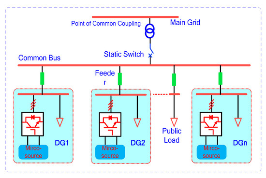
Figure 1.
A simplified schematic of the microgrid.
2.2. System Power-Sharing Mechanism and Conventional Droop Control
Once simplified, Figure 1 is equivalent to the model shown in Figure 2. The output port of the inverter is linked to the LCL filter, changing the feeder parameter characteristics of the low-voltage microgrid. The virtual impedance method is equivalent to adding together the output impedance value of each DG source at the same time [15,16]. Hence, the resistance of the feeder parameter can be neglected, and the equivalent reactance between DG sources to the common bus will be the main factor leading to improper power-sharing.
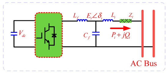
Figure 2.
Microgrid–DG connection.
In Figure 2, Vpcc ∠ 0° represents the voltage of the AC bus, Ei ∠ δi represents the output voltage of DG source DGi, and δi represents the angle difference between the DG output voltage and AC bus voltage. The active and reactive power of DG source DGi can be expressed as follows:
Normally, δi is small. According to their mathematical equivalents, active power Pi can be controlled by phase angle δi, and reactive power Qi can be adjusted by output voltage magnitude Ei. Based on this principle, active and reactive power are utilized to adjust the output frequency and voltage magnitude of the inverter in the conventional droop control, which is expressed in the following equation:
where ω* and E* are the frequency and magnitude of the DG source when not loaded, mi and ni are active and reactive droop gain, and Pi and Qi are the active and reactive power values of the distributed micro source under the actual frequency ωi and voltage Ei.
In a steady state, the frequency is of a global variety, so the active output power of each DG source can be accurately shared in terms of the droop gain. Output voltage is of a local variety, so the issue of reactive power-sharing may be analyzed. By plugging Equation (2) into (1), the reactive power can be derived:
To simplify the analysis process, the capacities of the two DG units DGi and DGj are assumed to be the same, and so are the droop gains. Note that the phase angle δi is small (sinδi ≈ δi, cosδi ≈ 1), so the reactive relative error of DGi can be depicted as:
From Equation (4), it can be seen that by reducing the feeder impedance difference between the various DG units, (Xj − Xi) can reduce errors in reactive power, increasing reactive droop gain nj and increasing feeder impedance Xj. Feeder impedance and feeder impedance differences can be adjusted through the virtual impedance method, but doing so will affect the output voltage magnitude.
The principle behind the sharing error reduction can be understood with the aid of Figure 3. If the sag factor nq is increased, the reactive power sharing error ΔQerr will converge. However, the associated operations will result in a decrease in point of common coupling (PCC) voltage Vpcc. Thus Figure 3 illustrates reactive power sharing between different DG units with mismatched feeder impedance. The output impedance is bigger and the output reactive power is smaller when the feeder voltage drops at the same rate. In Equation (4), the reactive power difference will be reduced when the reactive droop gain of DG sources is increased, but the effect will be subtle. Increased reactive gain can also result in output voltage dropping, possibly even beyond a stable range of operation, leading to a breakdown of the microgrid.
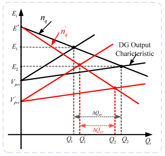
Figure 3.
Reactive power sharing of DG units with mismatched feeder impedance.
3. Reactive Power-Voltage Controller Design
3.1. A Reactive Power-Voltage Controller based on Adaptive Virtue Impedance
The analysis in Section 2.1 reveals that feeder impedance errors are the main factor affecting the accuracy of reactive power distribution. In order to improve the accuracy of reactive distribution under varying load conditions, this paper adopts the adaptive virtual impedance method to reconstruct the output impedance of DG units. The adaptive virtue impedance proposed in this paper is as follows:
where, X0 and Xvir are initial virtue impedance and total virtue impedance. Qi is the reactive power measured by a DG unit. Ki is the virtue impedance coefficient related to the reactive power. If there is no reactive load, Ki can be set to zero. Proper virtue impedance can improve system resistance characteristics, thereby enhancing system stability. The adaptive virtue impedance introduced in this paper is mathematically depicted as:
3.2. A Voltage Recovery Strategy Based on a Simultaneous Communication Mechanism
An adaptive virtue impedance reactive power-voltage controller can improve reactive distribution accuracy under light or heavy loads. However, the output voltage of the DG unit may drop when the load is heavy, affecting power quality. To overcome this shortcoming, a simultaneous compensation mechanism is adopted to raise the voltage. Simultaneous communication is used to raise the output voltage of the DG units. When an undervoltage signal is detected by a DG source, the compensation value ΔE0 is applied to all DG sources. When an overvoltage signal is detected, all compensation stops simultaneously. Hence, in this paper, the droop control method with voltage recovering mechanism is proposed as follows:
where, Gn is the synchronic signal andΔE0 is the compensation step. When Gn is 1, positive voltage recovery is initiated. When Gn is −1, negative voltage recovery is initiated. When Gn is 0, recovery is stopped. This can be mathematically described as:
To cope with the problem, the voltage recovery operation Gn will be performed. That is to say, if the output voltage Ei of one DG unit is less than its allowed low limit, then the DG unit will trigger the voltage recovery operation Gn until its output voltage is restored to rating value. The output voltage of all the DG units will be added an identical value ΔE0 to increase the PCC voltage Vpcc. The idea for the voltage recovery operation can be comprehended with the aid of Figure 4. As shown in Figure 4, the relative value of the DG sources will not be changed by synchronously raising the DG output voltage, therefore the active distribution behavior will not be affected. In addition, it should be noted that the time interval for the synchronous signal in Equation (8) is long and its order of magnitude is far bigger than the control cycle. A delay is assumed to exist in the synchronous signal, which means the time at which each DG unit receives the signal will be different, and a reactive power error will occur. However, the proposed adaptive virtue impedance strategy will rectify the DG output reactive power, achieving a new balance. Hence, this strategy has a low requirement for communication bandwidth and synchronism, a strong robustness, and maintains the plug-and-play solution of DG units in a microgrid.
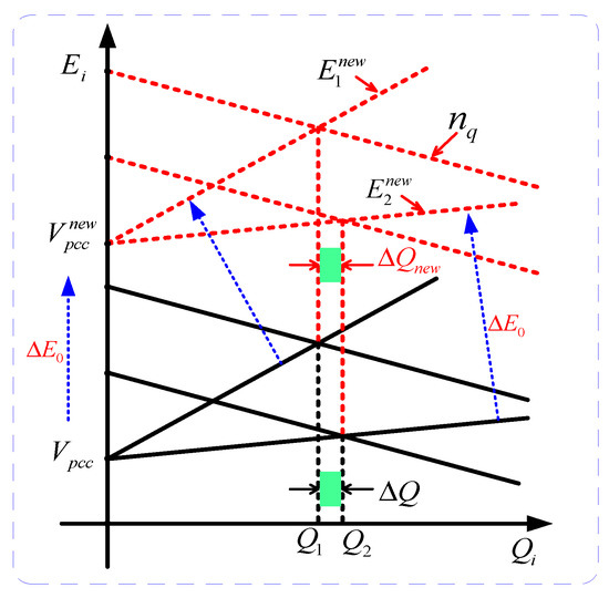
Figure 4.
Schematic diagram of the voltage recovery mechanism.
3.3. Reactive Error Analysis of the Adaptive Virtue Impedance Controller
To facilitate the analysis, it can be assumed that DGi and DGj of the same capacity operate in parallel, and their droop gains are the same. In addition, the virtue coefficients in this paper are set to be the same:
The adaptive virtue impedance proposed in this paper can be simplified as:
From Equation (4), the new reactive error after adopting the adaptive virtue impedance controller can be described as:
The following equation can then be obtained:
Simplifying Equation (12) results in the following:
From Equation (3),
Combining Equations (13) and (14) results in the following:
Utilizing the theory of equivalent voltage sources in Thevenin’s circuit, it can be deduced that:
where, Zeq is the internal impedance of the DG equivalent voltage source, including feeder impedance and virtue impedance, which is a resistance-inductance impedance. ii is the output current of the equivalent voltage source. Since , combining it with Equation (16) results in the following:
Combining Equations (15) and (17) results in the following:
Therefore,
Hence, the adaptive virtue impedance controller proposed in this paper can improve the accuracy of reactive distribution. Choosing a proper virtue impedance value and coefficient will allow the reactive error to be controlled within a certain range.
4. Simulation and Test
4.1. Simulation Results
In order to verify the effectiveness of the adaptive virtue impedance strategy and voltage recovery strategy proposed in this paper, a simulation model of an islanded microgrid system was constructed in Matlab/Simulink software. The control scheme for the single DG unit in the microgrid is shown in Figure 5, consisting of three DG units of 4 kVA and power loads. Samples were taken for the output current, voltage magnitude, and the filter current value. The adaptive virtue impedance strategy and voltage recovery strategy proposed in this paper were adopted. The feeders of the three DG units were considered to be 1 km, 1.5 km and 2 km, since the feeder coefficient of 1km is (Xl = 0.082 Ω, Rl = 0.54 Ω). The load active power was 5 kW, and reactive power was 5 kVar. The detailed DG coefficients are shown in Table 1.
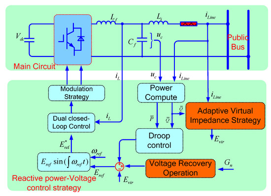
Figure 5.
Simulink scheme of the single DG unit.

Table 1.
The circuit and control parameters of the DG unit.
4.1.1. Simulation Case 1
Adopting the control method proposed in this paper, three DG units with the same capacity of 4 kVA operated in parallel to the public bus. The simulation result is shown in Figure 6. To facilitate the contrast, the conventional droop control strategy was adopted in the initial time interval t = [0 s, 1.5 s], only the adaptive virtue impedance strategy was adopted in the time interval t = [1.5 s, 3.0 s], and the activate voltage recovery operational strategy was adopted according to voltage drop in the time interval t = [3.0 s, 4.0 s].
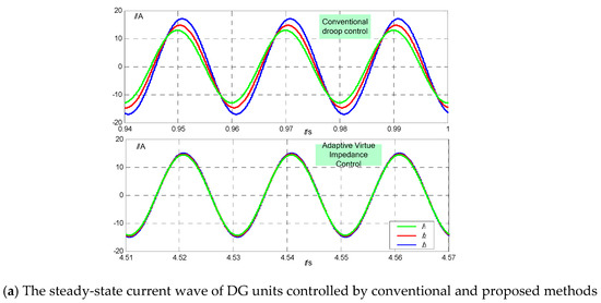
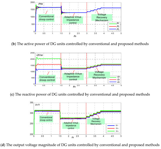
Figure 6.
Simulation results of Test 1.
Figure 6a illustrates the current wave of DG in a stable state under conventional control and proposed control methods. From the Figure, a large error exists in the phase and magnitude of the DG unit output current in a steady state. The output current magnitude difference between DG1 and DG3 is 5 A. The DG output current in a steady state when adopting the proposed method is almost the same, with circular current of nearly zero. Figure 6b,c shows the output active and reactive power of the DG unit under conventional and proposed control. When controlled by the conventional method, the output reactive powers of the DG units are 1.2 kVar, 1.6 kVar, and 2.1 kVar. When t = 1.5 s, the adoption of adaptive virtue impedance obviously improves the reactive distribution accuracy, with the output reactive powers of the DG units at 1.22 kVar, 1.25 kVar, and 1.28 kVar and circular current at nearly zero. However, the voltage-dividing caused by virtue impedance also lowers the system voltage level. After t = 3.0 s, the voltage recovery operation of the DG unit is activated, and the output reactive and active power value increases gradually, sharing loads collaboratively. From the figure, the operation will not affect reactive power allocation between DG units.
Figure 6d illustrates the output voltage magnitude of the DG units controlled by the conventional and proposed methods. Adaptive virtue impedance improves reactive power distribution accuracy, but also makes voltage drop to approximately 270 V. Voltage recovery operations can recover the system voltage to approximately 310 V without affecting the reactive power allocation, ensuring the rated active and reactive output are maintained. Therefore, this case verifies the effectiveness and feasibility of the adaptive virtue impedance and voltage recovery strategy proposed in this paper.
4.1.2. Simulation Case 2
In order to test the requirement for synchronous communication of the proposed control method, at t = 1.6 s, DG2 receives the synchronous signal 0.1 s in advance. At t = 2.1 s, the signal is received 0.1 s later. The synchronous signals for DG1 and DG3 are normal.
Figure 7a,b shows the simulation results of the output reactive power and voltage magnitude of three DG units when synchronous communication is abnormal. In contrast with the simulation results in case 1, the synchronous signal and asynchronous (delay or advance) signals affected the dynamic characteristics of reactive power, and the reactive difference between DG1 and DG2 increased from 40 Var to 100 Var. In the time intervals t = [1.6 s, 1.7 s] and t= [2.1 s, 2.2 s], a slight disturbance occurs in the output reactive power of the DG units. However, when the next normal synchronous signal is received, reactive allocation accuracy improves again because of the adaptive virtue impedance method, and voltage recovery operation with normal communication ensures each unit produces a rated reactive value. Figure 7b shows the output voltage magnitude of each DG unit a slight vibration appears in output voltage when communication is abnormal, but fundamental system voltage is not affected.
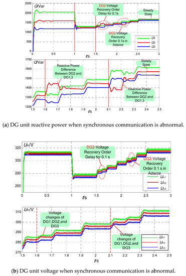
Figure 7.
Simulated results of Test 2.
Therefore, this case verifies that the voltage recovery operation adopted in this paper has a low requirement for communication bandwidth and consistency and has a strong robustness.
4.1.3. Simulation Case 3
This simulation tested the effect of the adopted method when a load changes suddenly. In the time interval t = [5.0 s, 7.5 s], the load increases reactive power to 2.5 kVar, causing a heavy reactive load. In the time interval t = [7.5 s, 10 s], the load reduces reactive power to 5.5 kVar, causing a light reactive load.
Figure 8a,b represents the reactive and active power allocation between three DG units when a load changes. Before t = 5.0 s, the system is in a steady state. Load vibration results in a voltage drop of virtue impedance. Although the reactive error is small, the system voltage level lowers, and the voltage recovery operation will be activated to bring the output voltage of the DG unit back to the rated level, ensuring the rated reactive power to be 2.40 kVar, 2.45 kV, and 2.48 kVar when the system is under heavy load. At t = 7.5 s, the reactive load decreases to 1.8 kVar. Although the system is under light load, proper reactive error is maintained, and the reactive power is 0.55 kVar, 0.60 kVar, and 0.68 kVar, respectively. Figure 8c illustrates the voltage magnitude change of the DG units, the output voltage of the DG changes when the load changes, but the system is maintained at a proper voltage level by positive and negative voltage recovery operations.
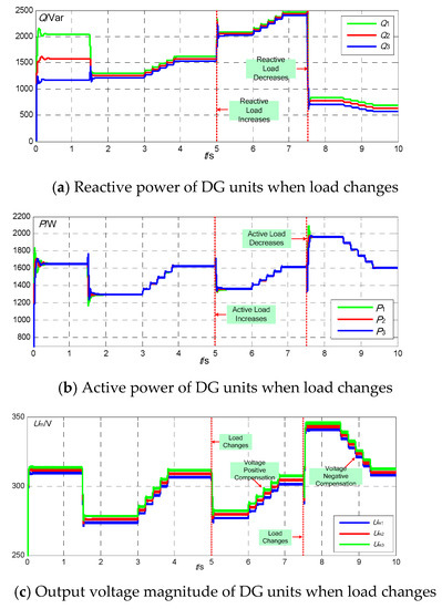
Figure 8.
Simulation results of Test 3.
Hence, this case verifies that the proposed method can be applied to the reactive distribution under different load conditions (light or heavy) and can keep the voltage level in a proper range.
4.2. Experimental Verification
In order to verify the proposed method, a simple experimental prototype with two DG units operating in parallel was built, with a switching device in its main circuit using CM75DY-24H, and the core control panel composed of DSP28335 and FPGA. The DC capacitance voltage of the prototype was 80 V. Control parameters are listed in Table 1. Resistance-inductance load was 16 Ω and 3 mH, and the switching frequency and sample frequency were both at 12.8 kHz. Voltage drop was not to exceed 10% of the rated value.
Figure 9 depicts the test waves of the output voltage, current, and circular current (I0H = I01 − I02) of two DG units under at a steady state. Since the feeders of the two DG units are different, certain phase and magnitude differences of the output current of the two DG units exist when adopting the conventional method. The system circular current is large, with I0H at approximately 1.2 A at peak. Figure 10 shows that, after adopting the proposed adaptive virtue impedance, the phase and magnitude of output current of the DG units are nearly consistent, and the peak value of the circular current I0H is about zero. However, the output voltage magnitude is below the rated value because of the voltage-dividing effect of the virtue impedance. In addition, as Figure 11 shows, no current overshoot phenomenon appears in the process of the circular current converging to zero, which presents a good dynamic characteristic.
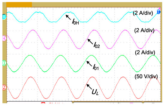
Figure 9.
Steady state experimental waveforms using the conventional method.
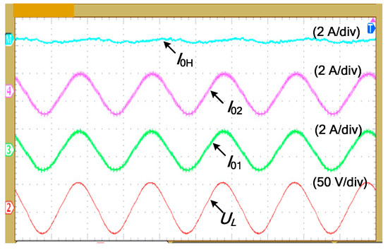
Figure 10.
Steady state experimental waveforms using the proposed method.
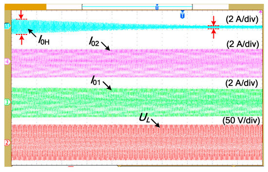
Figure 11.
The output current and circulating current waveform of the DG units in transience.
Hence, the above waves verify that the proposed method can improve the allocation accuracy of the reactive power, as well as lower the system voltage magnitude level.
To verify that the proposed adaptive virtue impedance strategy and voltage recovery operation can affect one another, two separate operations were performed. As shown in Figure 12, when adopting adaptive virtue impedance only, the system circular current converges to an extremely small value which is then maintained, while the system bus voltage declines gradually, with the lowest level at 5 V (10%), which is the voltage lower limit. Figure 13 illustrates the voltage magnitude of the DG units and bus. As depicted in the figure, the voltage recovery operation will not affect the system circular current, keeping it almost unchanged while the system bus voltage steadily recovers to the rated value.
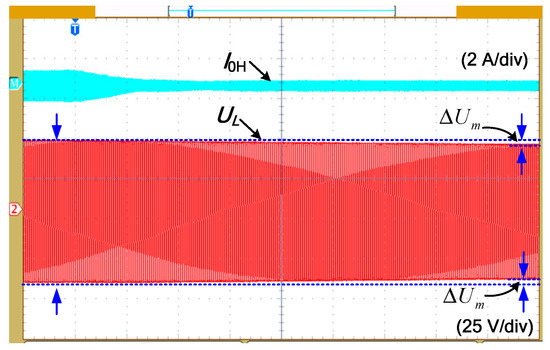
Figure 12.
The circulating current and PCC voltage of DGs using the adaptive virtual impedance method.
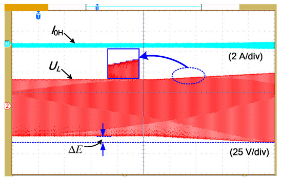
Figure 13.
The circulating current and PCC voltage of DGs when only voltage recovery operation is performed.
Therefore, the Figures below verify that the two methods adopted in this paper will not interrupt each other. The voltage recovery operation maintains the system bus voltage level within a reasonable range, while adaptive virtue impedance enhances reactive power allocation accuracy, allowing DG units to produce rated active and reactive power as well as share load collaboratively.
5. Conclusions
In order to analyze the voltage/reactive power droop characteristics of an AC microgrid, this paper proposes a reactive power-voltage control strategy for microgrids based on adaptive virtue impedance. The scheme adds adaptive terms to conventional virtue impedance, rectifies voltage reference values, and compensates DG output voltage by utilizing a voltage recovery mechanism activated by synchronous communication.
This paper verifies that the proposed method can reduce reactive error, and further verifies the effectiveness and feasibility of the method through simulation and testing. The adopted method only requires simple and low-bandwidth synchronous signal communication. Power information between different DG units is not used, and the plug-and-play characteristic of DG units is maintained. The scheme can be universally applied to a variety of microgrid structures and can even be applied to complicated structures, such as network microgrids.
Author Contributions
The paper was a collaborative effort between the authors. The authors contributed collectively to the theoretical analysis, modeling, simulation, and manuscript preparation.
Acknowledgments
This work was supported by a China National Energy Bureau project under the City-Park two levels of “Internet +” smart energy demonstration projects supporting the energy consumption revolution.
Conflicts of Interest
The authors declare no conflict of interest.
References
- Sun, Y.Z.; Mei, S.W. Exploring the new advantages of the electric power system through international cooperation. Sci. Found. China 2003, 17, 185–187. [Google Scholar]
- Jain, N.; Singh, S.N.; Wen, F.S. Distributed generation recent trends and future challenges. J. Electr. Power Sci. Technol. 2008, 23, 53–61. [Google Scholar]
- Song, D.R.; Li, Q.G.; Cai, Z.L.; Li, L.; Yang, J.; Su, M.; Young, H.J. Model predictive control using multi-step prediction model for electrical yaw system of horizontal-axis wind turbines. IEEE Trans. Sustain. Energy 2018. [Google Scholar] [CrossRef]
- Song, D.R.; Fan, X.Y.; Yang, J.; Liu, A.F.; Chen, S.F.; Young, H.J. Power extraction efficiency optimization of horizontal-axis wind turbines through optimizing control parameters of yaw control systems using an intelligent method. Appl. Energy 2018, 224, 267–279. [Google Scholar] [CrossRef]
- Cheng, P.T.; Chen, C.A.; Lee, T.L.; Kuo, S.Y. A cooperative imbalance compensation method for distributed generation interface converters. IEEE Trans. Ind. Appl. 2009, 45, 805–815. [Google Scholar] [CrossRef]
- Xie, L.L.; Shi, B.; Hua, G.Y.; Wen, F.; Yang, L.; Dong, Q. Parallel operation technology of distributed generations based on improved droop control. Power Syst. Technol. 2013, 37, 992–998. [Google Scholar]
- Guerrero, J.M.; De Vicuna, L.G.; Matas, J.; Castilla, M.; Miret, J. A wireless controller to enhance dynamic performance of parallel inverters in distributed generation system. IEEE Trans. Power Electron. 2004, 19, 1205–1213. [Google Scholar] [CrossRef]
- Song, D.R.; Yang, J.; Dong, M.; Young, H.J. Model predictive control with finite control set for variable-speed wind turbines. Energy 2017, 126, 564–572. [Google Scholar] [CrossRef]
- Tuladhar, A.; Jin, H.; Unger, T.; Mauch, T. Control of parallel inverters in distributed AC power systems with consideration of line impedance effect. IEEE Trans. Ind. Electron. 2000, 36, 131–138. [Google Scholar] [CrossRef]
- Zhang, Q.H.; Peng, C.W.; Chen, Y.D.; Jin, D.; Luo, A. A control strategy for parallel operation of multi-inverters in microgrid. Proc. CSEE 2012, 32, 126–133. [Google Scholar]
- Sao, C.K.; Lehn, P.W. Autonomous load sharing of voltage source converters. IEEE Trans. Power Deliv. 2005, 20, 1009–1016. [Google Scholar] [CrossRef]
- Zhong, Q. Robust droop controller for accurate proportional load sharing among inverters operated in parallel. IEEE Trans. Ind. Electron. 2013, 60, 1281–1290. [Google Scholar] [CrossRef]
- De Brabandere, K.; Bolsens, B.; Van der Keybus, J. A voltage and frequency droop control method for parallel inverters. IEEE Trans. Power Electron. 2007, 22, 1107–1115. [Google Scholar] [CrossRef]
- Li, Y.W.; Kao, C.N. An accurate Power Control Strategy for power Electronics Interfaced distributed Generation Units operating in a Low Voltage multibus microgrid. IEEE Trans Power Electron. 2009, 24, 2977–2988. [Google Scholar]
- Ma, T.Y.; Jin, X.M.; Liang, J.G. Multiple virtual impedance control method of micro-grid converter under island mode. Trans. China Electrotech. Soc. 2013, 28, 304–312. [Google Scholar]
- Wei, Y.; Min, C.; Matas, J.; Guerrero, J.M.; Qian, Z.M. Design and Analysis of the Droop Control Method for Parallel Inverters Considering the Impact of the Complex Impedance on the Power Sharing. IEEE Trans. Ind. Electron. 2011, 58, 576–588. [Google Scholar]
- Yu, W.; Xu, D.H. Control scheme of paralleled UPS system based on output virtual resistance. Proc. CSEE 2009, 29, 32–39. [Google Scholar]
- He, J.W.; Li, Y.W. An Enhanced Microgrid Load Demand Sharing Strategy. IEEE Trans. Power Electron. 2012, 27, 3984–3995. [Google Scholar] [CrossRef]
- Han, H.; Liu, Y.; Sun, Y.; Su, M.; Guerrero, J.M. An Improved Droop Control Strategy for Reactive Power Sharing in Islanded Microgrid. IEEE Trans. Power Electron. 2015, 30, 3133–3141. [Google Scholar] [CrossRef]
- Mohsen, E.; Li, L. Microgrid operation improvement by adaptive virtual impedance. IET Renew. Power Gener. 2018, 13, 296–307. [Google Scholar]
- Hanqing, Y.; Qi, L.; Weirong, C. Microgrid Communication System and Its Application in Hierarchical Control; Academic Press: New York, NY, USA, 2019. [Google Scholar]
- Hou, X.; Sun, Y.; Han, H.; Liu, Z.; Yuan, W.; Su, M. A fully decentralized control of grid-connected cascaded inverters. IEEE Trans. Sustain. Energy 2019, 10, 315–317. [Google Scholar] [CrossRef]
- Liu, Z.; Su, M.; Sun, Y.; Li, L.; Han, H.; Zhang, X.; Zheng, M. Optimal criterion and global/sub-optimal control schemes of decentralized economical dispatch for AC microgrid. Int. J. Electr. Power Energy Syst. 2019, 104, 38–42. [Google Scholar] [CrossRef]
- Lyu, Z.; Wei, Q.; Zhang, Y.; Zhao, J.; Manla, E. Adaptive Virtual Impedance Droop Control Based on Consensus Control of Reactive Current. Energies 2018, 11, 1801. [Google Scholar] [CrossRef]
- Morteza, A.; Rokrok, E. An Improved Centralized Control Structure for Compensation of Voltage Distortions in Inverter-Based Microgrids. Energies 2018, 11, 1862. [Google Scholar]
- Hou, X.; Sun, Y.; Zhang, X.; Lu, J.; Wang, P.; Guerrero, J.M. Improvement of Frequency Regulation in VSG-Based AC Microgrid via Adaptive Virtual Inertia. IEEE Trans. Power Electron. 2019. [Google Scholar] [CrossRef]
- Zhang, L.; Chen, K.; Lyu, L.; Cai, G. Research on the Operation Control Strategy of a Low-Voltage Direct Current Microgrid Based on a Disturbance Observer and Neural Network Adaptive Control Algorithm. Energies 2019, 12, 1162. [Google Scholar] [CrossRef]
- Chang, Y.; Xie, P.; Dan, Y.; Xiao, X. Transient Stability Analysis of Islanded AC Microgrids with a Significant Share of Virtual Synchronous Generators. Energies 2018, 11, 44. [Google Scholar] [CrossRef]
- Rocabert, J.; Luna, A.; Blaabjerg, F.; Rodriguez, P. Control of power converters in AC microgrids. IEEE Trans. Power Electron. 2012, 27, 4734–4749. [Google Scholar] [CrossRef]
- Lu, Z.X.; Wang, C.X.; Min, Y.; Zhou, S.; Lv, J.; Wang, Y. Overview on microgrid research. Autom. Electr. Power Syst. 2007, 31, 100–107. [Google Scholar]
- Guerrero, J.M.; Loh, P.; Chandorkar, M. Advanced Control Architectures for Intelligent MicroGrids-Part I: Decentralized and Hierarchical Control. IEEE Trans. Ind. Electron. 2013, 60, 1254–1262. [Google Scholar] [CrossRef]
- Wang, C.S.; Gao, F.; Li, P.; Huang, B.; Ding, C.; Yu, H. Control strategy research on low voltage microgrid. Proc. CSEE 2012, 32, 2–8. [Google Scholar]
- Yang, X.F.; Su, J.; Lv, Z.P. Overview on micro-grid technology. Proc. CSEE 2014, 34, 57–70. [Google Scholar]
- Guerrero, J.M.; Vasquez, J.C.; Matas, J.; De Vicuña, L.G.; Castilla, M. Hierarchical control of droop-controlled ac and dc microgrids-a general approach towards standardization. IEEE Trans. Ind. Electron. 2011, 58, 158–172. [Google Scholar] [CrossRef]
- He, J.W.; Li, Y.W. Analysis, Design, and Implementation of Virtual Impedance for Power Electronics Interfaced Distributed Generation. IEEE Trans. Ind. Appl. 2012, 47, 2525–2538. [Google Scholar] [CrossRef]
© 2019 by the authors. Licensee MDPI, Basel, Switzerland. This article is an open access article distributed under the terms and conditions of the Creative Commons Attribution (CC BY) license (http://creativecommons.org/licenses/by/4.0/).