Abstract
This paper presents two control strategies: (i) An optimal exergy destruction (OXD) controller and (ii) a decentralized power apportionment (DPA) controller. The OXD controller is an analytical, closed-loop optimal feedforward controller developed utilizing exergy analysis to minimize exergy destruction in an AC inverter microgrid. The OXD controller requires a star or fully connected topology, whereas the DPA operates with no communication among the inverters. The DPA presents a viable alternative to conventional droop control, and does not suffer from fluctuations in bus frequency or steady-state voltage while taking advantage of distributed storage assets necessary for the high penetration of renewable sources. The performances of OXD-, DPA-, and droop-controlled microgrids are compared by simulation.
1. Introduction
High penetration levels of renewable energy sources, such as wind and solar, provide unique challenges for the future power grid which require new control techniques. Current grid control, based on excess generation and the open-loop control of power flow from sources to loads, is not transferrable to microgrids with high penetration of renewable sources. Microgrids are broadly categorized as either: (i) Islanded microgrids, which are altogether isolated from any other energy grid; or (ii) networked microgrids, which are coupled to either other microgrids or to a large utility grid [1,2].
The following work focuses on islanded, inverter-based AC microgrids, as shown in Figure 1. Numerous control strategies exist for inverter-based AC microgrids, as has been discussed by Hossain et al. [3]. Optimal control strategies require ubiquitous communication among the microgrid [4]; which, in turn, yields numerous benefits (as presented in [5,6,7,8,9]), including hierarchal control optimization strategies with the ability to optimize fuel consumption and emission pollutants [8]. Despite the numerous control schemes and benefits presented in [3,5,6,7,8,9], the authors are not aware of any publications that have described analytical, closed-form optimal solutions or decentralized alternative control schemes for inverter-based AC microgrids, which are the voids this manuscript aims to fill.
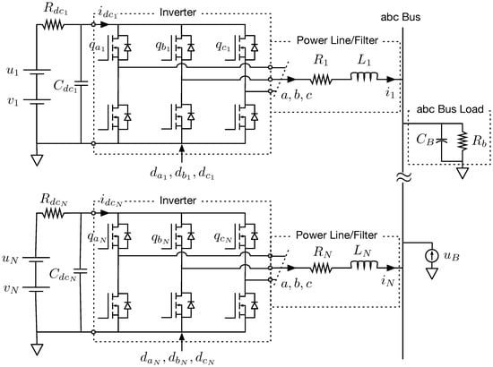
Figure 1.
Schematic of an N-inverter system in the domain.
Wilson et al. [10] provided a solution to the problem of regulation and power balance in an AC inverter microgrid with high penetration levels of stochastic renewable sources by employing distributed storage. Through the use of distributed storage, they were able to maintain a constant bus voltage despite significant fluctuations from stochastic sources [10]. Employing energy storage can be costly, both financially and in terms of system efficiencies. Thus, it is desirable to maximize the power delivered to the microgrid’s bus load, which, in turn, minimizes utilization of energy storage.
To maximize the power delivered to the microgrid’s bus load, exergy analysis will be used. Exergy is the maximum useful work potential of a system that can theoretically be extracted during a process. The work done W in a given process is a function f of the initial state, process path, and final state. The work done is maximized when the process path is reversible. Thus, the work potential is determined by employing reversible processes. In any real-world process, irreversibilities cause some work potential to be wasted. The wasted work potential is known as exergy destruction , which must be greater than or equal to zero [11].
The proposed optimal exergy destruction (OXD) feedforward controller minimizes the exergy destruction rate in transferring energy from the source to the bus load, which maximizes the useful work potential delivered to the bus load. In this study, ideal storage elements are used; however, as energy storage for islanded microgrids expands beyond conventional fossil fuels to include combinations of chemical potential energy, electrical potential energy, and mechanical potential energy—such as flow batteries, super capacitors, and flywheels—the optimal exergy analysis presented here can be expanded to include non-ideal storage models.
There are two parts to the control of the microgrid: Feedforward inverter controls and the Hamiltonian-based feedback control. The optimal exergy destruction (OXD) controller is a centralized feedforward controller that identifies the inverter operating set points which will maximize the power delivered to the load by utilizing exergy analysis while minimizing the exergy destruction. The Hamiltonian-based feedback controller is a local, decentralized controller designed to minimize the bus load voltage variations with respect to a reference bus voltage [10]. To implement the OXD, ubiquitous communication is required. The motivation for the development of the decentralized power apportionment (DPA) feedforward controller was to: (i) Eliminate the need for a fully connected or star topology, such as that required by the OXD guidance law, while preserving the ability to maintain a constant bus voltage through both load and source fluctuations; and (ii) fill a vacancy in the decentralized control of three-phase AC inverter microgrids.
Decentralized droop controllers exist for three-phase AC inverter microgrids, but the conventional droop control is unable to: (i) Maintain a constant frequency through bus load fluctuations, (ii) maintain a constant bus voltage without the aid of an outer control loop, (iii) maintain a constant bus voltage in the event that a source goes offline without an outer loop controller, or (iv) take advantage of the distributed storage devices required for the high penetration of renewable sources [12,13,14,15,16]. The decentralized power apportionment scheme proposed in this paper fills the voids left by conventional droop control. The primary objective of both the OXD and DPA approaches is to maintain a specified bus voltage in the presence of source or load variability. Second, the OXD guidance law minimizes the exergy destroyed in the electrical microgrid. Decentralized microgrid control schemes can lead to the use of storage, even when there is enough generation capacity to meet the total load. Therefore, a secondary objective of the DPA guidance law is to avoid storage use in steady-state operation.
First, this manuscript builds upon the work of [10] to show feedback control dynamic stability of the Hamiltonian-based feedback controller developed in [10]. After stability of the feedback controller developed in [10] has been established, the OXD and DPA feedforward controllers are developed, which are the main contributions of this manuscript. In Section 6, the DPA approach is first compared to the conventional droop control. Then, the decentralized power apportionment method is compared to the optimal exergy destruction scheme through simulation. Finally, in Section 7, the results are summarized.
2. AC Inverter Microgrid Model
The AC inverter microgrid model of [10] was expanded to N three-phase inverters, which are connected to a common wye-connected three-phase parallel resistor and capacitor balanced AC bus load, as shown in Figure 1. The load is sourced by N renewable, stochastic energy sources () in series with energy storage devices (). The AC output voltages of the jth inverter () are controlled by the duty cycles (). An additional energy storage device is collocated with the load () [10,17]. The time-varying nature of the state equations can be removed by utilizing the Parks power-invariant reference frame transformation, yielding a DC-like system, as shown in Figure 2. This reference frame transformation has been done by [17] to create a reference frame model for a two inverter microgrid, as shown in Figure 2 with . The state equations for the jth AC inverter are given in (1), where a DC capacitor (), which was introduced as in [10], provides the ability to control the DC input voltage to the inverter [10,17]:
where
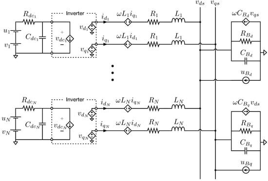
Figure 2.
Schematic of an N-inverter system in the domain.
- = jth inverter output voltage angle relative to current,= ,
- = AC angular frequency,
- = ,
- = ,
- = DC voltage source to the jth inverter,
- = DC input voltage of the jth inverter,
- = -axis output voltage of the jth inverter,
- = -axis output voltage of the jth inverter,
- = d-axis AC bus voltage,
- = q-axis AC bus voltage,
- = d-axis current of the jth inverter,
- = q-axis current of the jth inverter,
- = equivalent inverter input resistances of the jth inverter,
- = capacitor on the DC side of the jth inverter,
- = depth-of-modulation of the jth inverter,
- = power line LR filter inductance for the jth inverter,
- = power line LR filter resistance for the jth inverter,
- = ideal voltage storage for the jth inverter,
- = ideal current storage on the d-axis bus load,
- = ideal current storage on the q-axis bus load.
The corresponding bus equations in the reference frame are [17]
The full model development can be found in [10,17].
3. Hamiltonian Surface Shaping and Power Flow Control
3.1. State Variable Stability
The ideal energy storage devices of the system () were used in [10,17] as control inputs to develop a feedback controller, utilizing Hamiltonian surface shaping and power flow control (HSSPFC) techniques, which ensures stability while satisfying time-varying bus loads [10,17,18]. The state variable model of [17], which was modified by [10] by the addition of , has been expanded to N inverters, where is the state vector, is the N stochastic source vector, and is the input vector [10,17]:
The reduced order model, in matrix form, is [10,17]:
with expanded for N inverters as [10],
where has been partitioned into the diagonal and skew-symmetric matrices and , respectively [10]:
The significance of [10] in adding into the microgrid architecture of [17] shows up mathematically in (4), where the and terms are all contained in . Without , the and terms are in both and .
The derivation of the Hamiltonian-based feedback controller for this architecture of AC inverter microgrids, along with the dynamic stability condition and simulation studies, can be found in [10]. Before the development of the feedforward control laws, feedback control dynamic stability of the feedback controller will be addressed, which was not covered in [10].
3.2. Feedback Control Dynamic Stability
Asymptotic stability of the system is shown through Theorem 1 from Schaub and Junkins [19], including the control dynamics of .
Theorem 1.
Assume there exists a Lyapunov function of the dynamical system . Let Ω be the non-empty set of state vectors such that
If the first derivatives of , evaluated on the set Ω, are zero
and the kth derivative is negative definite on the set Ω
then, the system is asymptotically stable if k is an odd number [19].
Following the Hamiltonian-based feedback control law derivation and notation in [10], the system error state and control inputs are defined as
where the reference state and control vectors are [10]
Utilizing Theorem 1 and the matrix mathematics laid out in [10,20], one finds that
The second time derivative of the Hamiltonian is [20]
and the third time derivative of the Hamiltonian is [20]
and
Three is an odd number; thus, the feedback dynamical system is asymptotically stable by Theorem 1. Dynamic stability for the feedback controller has been thoroughly addressed, allowing for the creation of: (i) An optimal exergy destruction (OXD) feedforward controller and (ii) a decentralized power apportionment (DPA) feedforward controller.
4. Optimal Exergy Destruction
The Optimal Exergy Destruction (OXD) feedforward control developed in the following section has the primary goal of minimizing the degradation of energy quality by reducing the system’s exergy destruction rate. The exergy destruction of an electrical system occurs due to the heat transfer to the environment by the electrical resistance and, thus, the microgrid’s total rate of exergy destruction is
The OXD guidance law’s secondary goal is to avoid storage use when the power available is greater than the load. To accomplish both goals, the OXD controller will determine the necessary inverter controls to be used as feedforward terms, as well as the reference DC input voltage () for the Hamiltonian-based feedback controller. It is assumed that the d-axis and q-axis bus voltages are specified. The OXD guidance law will be used as the benchmark for comparison of the decentralized consensus alternative, which has no peer-to-peer inverter communication.
The OXD approach is developed from the steady-state () balanced power flow (),
The steady-state, power balanced form of (2) is
Let
where
ensures that (15) and (16) are satisfied by balancing the load requirements with the energy supplied by the inverters, which eliminates the need for storage . Combining (16) and (17) yields
where and are functions of and other known quantities.
Wilson et al. [10] provided a method to solve for , and for sources. This method can be expanded to sources, yielding
and
Through substitution, , , , , and can be expressed in terms of , which allows one to resolve out the constraints of (15) and (16). This leaves only the single constraint given by (18).
The DC input voltage to the jth inverter, , is a function of , , , and . Both and are functions of and , meaning that can be written as a function of only and . Inspection of (21) reveals that will be maximum when and are at minima. Thus, to minimize the rate of exergy destruction in the system, the cost function does not need to include the term of (14),
Augmenting (23) with (18) yields
where is a Lagrange multiplier. The analytical closed-form optimal feedforward control is derived from the necessary conditions, using
Substituting into produces
5. Decentralized Power Apportionment
The motivation for development of the decentralized power apportionment (DPA) guidance law below is to eliminate the requirement of a star or fully connected topology, as required by the OXD guidance law, while still providing a regulated bus on an islanded microgrid with high penetration of stochastic renewable sources. To calculate the currents of the OXD approach of (28), either: (i) Each inverter is aware of all N inverter resistances and online status in order to locally calculate its reference current, or (ii) a centralized controller must be aware of all N inverter resistances and online status, calculate each inverter’s reference currents, and then communicate that to each inverter controller. The DPA approach eliminates the need for a star topology which enhances the microgrid’s stability. The primary goal of the DPA control scheme is to maintain the specified bus voltage through source or load fluctuations. A supporting goal of the DPA feedforward controller is to avoid driving steady-state energy storage employment, in order to minimize the cost of the high penetration of renewable sources, while simultaneously reducing exergy destruction due to storage utilization. A tertiary goal of the DPA is to obtain OXD steady-state operation. Additionally, the DPA feedforward controller must not disrupt the Hamiltonian-based feedback control law’s objective of maintaining a constant bus voltage through sources and load fluctuations. Development of the DPA feedforward controller begins with the system’s balanced power flow,
This yields the reference states, as
One key aspect of an AC inverter microgrid utilizing the Hamiltonian feedback controller presented in [10] is that the power balance state of the microgrid is indicated by the employment of bus storage. For example, it is known that the power supplied by the inverters is insufficient when the bus storage is supplying. Conversely, it is known that the inverters are over-powering the bus load when the bus storage level is increasing. Similar to the decentralized mode adaptive guidance law of [21] for DC microgrids, the decentralized power apportionment guidance law for AC inverter microgrids exploits the state of the bus storage to indicate the power balance of the microgrid, and then adjusts accordingly.
Let and represent the power delivered to the d-axis and q-axis bus loads, respectively, from the jth inverter. Let and represent the jth inverter’s perceived bus load power requirements of the d-axis and q-axis bus loads, respectively, where the “perceived bus load power” may vary from the actual bus load power requirements. The jth inverter’s perceived bus powers are the DPA feedforward controller’s estimates of the actual bus load requirements, which is done independent of information from any other inverter controllers. The jth inverter is capable of tracking the actual bus power through bus load fluctuations; if the initial perceived bus powers match the actual bus load power requirement, then the jth inverter’s DPA guidance law will be able to accurately track the bus load fluctuations. The jth inverter’s perceived bus power will deviate from the actual bus power when source fluctuations are large enough to activate bus storage, a consequence of eliminating communication among the inverters. The DPA guidance law responds as though all fluctuations are load variations and adjusts appropriately, according to the following methodology.
The ratio of the jth inverter’s power requirement () to the jth inverter’s perceived bus power () is
The DPA guidance law is tasked with driving all energy storage use to zero in steady-state without disrupting the feedback controller’s objective of maintaining the specified bus voltage. Hence, the update rate of the outer loop DPA controller is run k times slower than the fast, inner loop Hamiltonian feedback control law after a deviation from zero storage usage. Utilizing (31), the jth inverter can locally track its power requirements by
where () are the initial -axes power requirements for the jth inverter. Similarly, the jth inverter can locally track its -axes perception of the bus load power by
Defining the jth inverter efficiency, , as the ratio of the power delivered to the bus to the total bus load power plus the electrical exergy destruction rate of the jth inverter, we have
The decentralized power apportionment solution is obtained by rearranging (34),
Utilizing (35), the DPA currents can be found:
The DPA reference current Equation (36) is similar the OXD optimal reference current Equation (28). The significant differences between the two equations is that OXD (28) requires a summation over all inverters, , which mandates a fully connected or star topology in order to accommodate the stochastic nature of renewable energy sources as they come online and go offline, as well as instantaneous bus load knowledge (). The DPA control scheme has eliminated the need for instantaneous system-wide information. Substituting (36) into (35) provides a solution to the efficiency of the inverter,
Equations (31), (32), (33), and (37) allow for the efficiency of an inverter to be updated without a centralized controller or any communication among inverters. All storage elements will be driven to zero, assuming that the inverters are capable of powering the bus load. In the event that the inverters are under-powered, the DPA guidance law will drive all inverter storage elements to zero and make up the power deficit with the bus storage.
6. Discussion and Simulation Results
Conventional droop control is a common decentralized control method for islanded AC inverter microgrids, which will be used as a basis of comparison for the decentralized power apportionment approach presented in Section 5. While all three control methods are designed to maintain a specified bus voltage, droop control depends on the implementation of a virtual impedance to share the bus currents among the inverters, while both the DPA and OXD approaches are based on HSSPFC techniques which take advantage of distributed storage making it possible for the high penetration of stochastic renewable sources. The key differences among OXD, DPA, and the conventional droop control resides in the communication requirements to implement the control scheme. In the case of OXD and DPA, said communication differences affect the storage requirements to actuate the microgrid. These communication requirements are summarized in Table 1, where the jth inverter’s known quantities are: , , , , , , , , , , and . Figure 3 provides corresponding block diagrams for the OXD and DPA control methods.

Table 1.
Comparison of control methods.
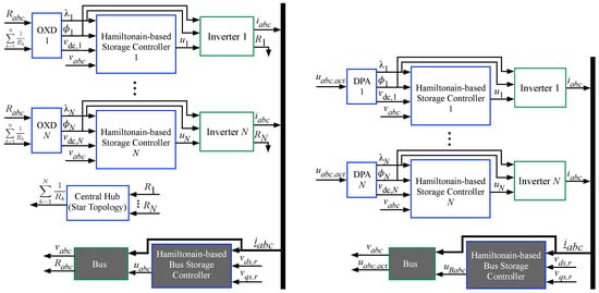
Figure 3.
(a) OXD block diagram. (b) DPA block diagram. The jth inverter known quantities have been omitted, for simplicity.
While OXD and DPA can handle an inverter going offline with no additional communication requirements than those specified in Table 1, the conventional droop control requires either an outer loop controller or the adjustment of all inverter references. To bring a new inverter online using the DPA approach, the controller will have to be given initial power requirements and perceived bus powers (, , ), but no communication among the inverters is required. To bring an inverter online utilizing conventional droop control would require either an outer loop controller or the adjustment of all inverter references. In the following subsections, steady-state and dynamic responses are presented, in order to highlight the similarities and differences between the the control methods.
To analyze the dynamic responses, an N-inverter microgrid simulation was created using the MathWorks MATLAB/Simulink environment. The primary subsystems, implemented as c-coded S-Functions, were: The grid model of (1) and (2); the Hamiltonian-based feedback control law of [10]; the OXD guidance law from Section 4; and the DPA guidance law from Section 5. Conventional droop control was implemented as in [12,13]
where and are the inverter reference angular frequency and peak voltage, respectively. The no-load angular frequency and peak voltage reference values are and , respectively. The real and reactive power droop gains are given by and , respectively [12,13].
To independently verify the accuracy of the Simulink models, a two-source inverter microgrid was built utilizing a Typhoon HIL 602 [22] to implement the microgrid shown in Figure 1. The OXD, DPA, and droop control schemes were run separately on an Opal RT OP5700, as c-coded S-functions, using RT-Lab [23], yielding a controller-in-the-loop (CIL). Communication channels between the Typhoon HIL 602 and Opal RT OP5700 are described in Table 2 and presented in Figure 3. Sixteen-bit analog voltages were calibrated and scaled to utilize the full range of the analog-to-digital converter (ADC) and digital-to-analog converter (DAC). The blue blocks in Figure 3 identify the controllers implemented on the Opal RT OP5700 and the green blocks identify the AC inverter microgrid implemented on the Typhoon HIL 602. The microgrid parameters are provided in Table 3.

Table 2.
Communication channels between the Typhoon HIL and Opal RT for a two-source inverter microgrid.

Table 3.
Typhoon HIL 602 parameters.
6.1. Model Verification
The MathWorks MATLAB/Simulink models, implemented as c-coded S-Functions, were verified in a scenario that doubled the bus load power by stepping the bus load resistance from to at time s for a balanced, wye-connected RC load. Then, at time s, the source V was stepped to V. The simulations were conducted at 60 Hz with a balanced load. The feedback controller time step was 10 s, and the Typhoon HIL 602 parameters for all control methods are provided in Table 3.
The results of the model verification tests are shown in Figure 4, where it can be seen that the MATLAB/Simulink models matched the Typhoon HIL 602 implemented microgrid. All three control methods successfully compensated for the bus load power increase. As expected, the OXD and DPA controlled microgrids were able to return the bus to following the source step change, whereas the droop controlled microgrid experienced a drop to .
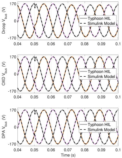
Figure 4.
Model Verification: Typhoon HIL 602 three-phase bus voltage response to a bus load step change at s and a source step change at s, overlaid with c-coded S-Functions simulation results for all three control methods: droop, OXD, and DPA.
After verification of the MathWorks MATLAB/Simulink models, the simulated microgrid was expanded to for further study. The following simulated scenarios were conducted at 60 Hz with a balanced load. The time step of the feedback controller was 10 s with the parameters provided in Table 4.

Table 4.
Simulation parameters.
6.2. Scenario 1: Bus Load Step Change
The optimal exergy destruction, decentralized power apportionment, and conventional / droop control were first compared by stepping the bus load resistance from to at s. The three-phase bus voltage response to the step change is shown in Figure 5a for all control methods. The three control methods had similar dynamic responses, with the key differences materializing in the droop controller’s inability to return the bus voltage back to the reference value, as well as adjusting the angular frequency from 60 Hz, as shown in Figure 5a. The OXD control scheme determined the new inverter set points in one iteration and returned the bus voltage back to the reference value, V. The initial adjustment made by the DPA fell short of the OXD solution. The DPA guidance law then waited () before making a second, more granular adjustment to return the bus voltage back to the reference value. The conventional droop controlled microgrid made an initial adjustment, which also fell short of the OXD solution. Unlike the DPA-controlled microgrid, the droop-controlled microgrid bus voltage did not return to the reference bus voltage. Additionally, the droop-controlled microgrid experienced a 0.3% increase in the angular frequency after reaching steady-state, whereas the OXD and DPA control schemes held constant, at 60 Hz.
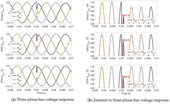
Figure 5.
Scenario 1: (a) Three-phase bus voltage response to a bus load step change at s for all three control methods: droop, OXD, and DPA. (b) Zoomed-in response to a bus load step change at s, to more easily identify performance differences.
An outer loop controller would have to be used in order for the conventional droop control to be able to return the bus voltage back to 170 V or hold the angular frequency at 60 Hz, which would make it no less decentralized than the DPA approach. Without the aid of a secondary control loop, the conventional droop control will suffer from both bus voltage and angular frequency variations if an inverter goes offline or has a significant change in its output, as is common in renewable sources such as photovoltaic arrays and wind turbines. Finally, the DPA-controlled microgrid operated at a fixed frequency, whereas the angular frequency of a conventional droop-controlled microgrid fluctuated, according to (38).
6.3. Scenario 2: Bus Load and Source Step Change
Scenario 2 was designed to demonstrate how the decentralized power apportionment scheme works without communication among the inverters. In this scenario, a bus load step change that doubles the bus load power was followed by the elimination of the largest voltage source and its accompanying storage, as shown in the top two plots of Figure 6a. The purposes of this scenario were to highlight: (i) The ability of the DPA to function similarly to the OXD when initiated in an OXD state, and (ii) the ability of the DPA to adapt to an inverter being suddenly disconnected from the microgrid with no communication among the inverters.
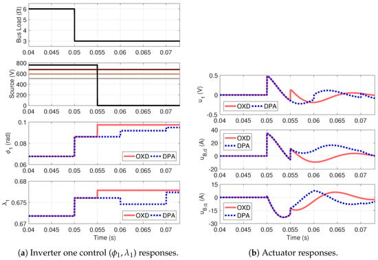
Figure 6.
Scenario 2: OXD and DPA: (a) inverter one controls the () response and (b) controlled storage response to a bus load step at , followed by the largest inverter being eliminated from the microgrid at .
At s, the bus resistance decreased from to and both the OXD and DPA were able to calculate new setpoints (, ) for the inverters in one iteration, as shown in Figure 6a (where only and are shown, for clarity). When the load power increased at s, Figure 6b shows the activation of both the source- and load-side storage by the feedback controller, in order to regulate the bus voltage. At s, inverter V and its accompanying storage were removed from the microgrid. The OXD guidance law was able to determine the new set points for all remaining inverters in one iteration, because it is immediately aware that the inverter fell offline, as reflected in Figure 6a. Storage utilization is simultaneously adjusted at s by the feedback controller to accommodate the system response to the power increase and new setpoint while regulating the bus voltage, as shown in Figure 6b and Figure 7. As , the DPA controller did not adjust the inverter controls until s, as shown in Figure 6a. During the interim, storage usage was adjusted by the feedback controller to maintain a constant bus voltage, despite the largest source dropping out, as shown in Figure 6b and Figure 7. Figure 6a shows the new inverter control values determined by the DPA at s, which drove the storage usage closer to zero, as reflected in Figure 6b. At s, Figure 6b indicates that the storage usage was still non-zero and, thus, the DPA made another correction to the inverter control values, as presented in Figure 6a. The DPA will continue to converge to a solution that requires no storage, stopping when it reaches a user-defined threshold for storage usage. In the above simulation, the threshold was set to A.
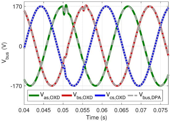
Figure 7.
Scenario 2: OXD and DPA bus voltage response to the bus load step at s followed by the largest inverter being eliminated from the microgrid at s. OXD controlled bus voltage is shown in red, green, and blue, with the DPA controlled bus voltage overlayed in gray.
The bus voltage is shown in Figure 7, which highlights the ability of the feedback controller to hold a specified bus voltage while the OXD and DPA feedforward controllers adjust the inverter set points to a power-balanced state, requiring no storage. The DPA-controlled microgrid will always utilize more storage than the OXD-controlled microgrid, due to the time it takes to converge to a solution. The length of time the DPA takes to arrive at a solution can be reduced by trimming the scalar constant k, as demonstrated in the next scenario.
6.4. Scenario 3: Stochastic Sources and Load
The cost of eliminating the ubiquitous communication network required by the OXD guidance law is an increased reliance on storage, as demonstrated by Scenario 2. In this scenario, the scalar constant was decreased to . This case study was designed to simulate stochastic renewable sources powering a stochastic load. Normally distributed sources with means at = [507, 592, 677, 762] V and variance of 50 were used, in conjunction with a normally distributed bus load with a mean of and variance of 2, as shown in Figure 8a. The bus capacitance was increased to F to help reduce the ripples caused by the stochastic nature of the sources.
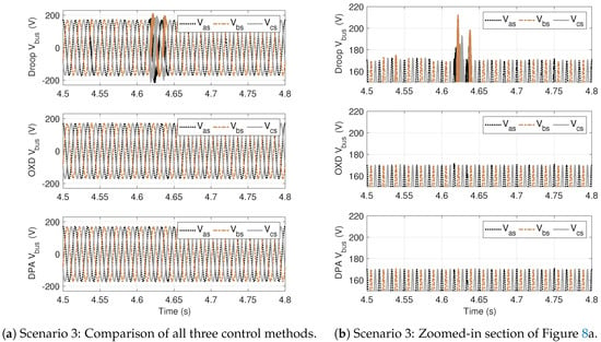
Figure 8.
Scenario 3: (a) The bus voltage for conventional droop, OXD, and DPA control methods for stochastic sources powering a stochastic load; (b) OXD and DPA control methods outperform the conventional droop, in terms of bus voltage regulation.
The source storage response for is shown in the top plot of Figure 9b. In Scenario 2, the source storage only responded every 1 ms. In this scenario, , which allowed the bus storage to adjust every s. The OXD-controlled bus storage responded faster, adjusting every s. While the storage usage of the DPA-controlled microgrid was reduced, it was still greater than the OXD solution.
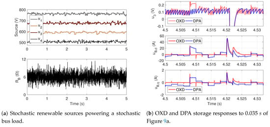
Figure 9.
Scenario 3: (a) Stochastic renewable sources powering a stochastic bus load and (b) a small portion of the corresponding OXD and DPA storage responses. For clarity, only source storage was plotted.
The bus voltage for all three control methods is shown in Figure 8a, which demonstrates the superiority of the OXD and DPA control methods over the conventional droop for stochastic renewable sources powering a stochastic load. Taking full advantage of the distributed storage, the feedback controller is able to hold the intended peak value of with less than 1.5% deviation, as reflected in Figure 8b. During the five-second simulation, conventional destroyed 32.0% more exergy than the optimal solution and the DPA-controlled microgrid destroyed 12.9% more exergy than the optimal solution, with totals provided in Table 5.

Table 5.
Comparison of the exergy destruction for the different control methods.
7. Conclusions
This paper presented (i) an analytical, closed-loop optimal feedforward controller, which was developed by utilizing exergy analysis, to minimize exergy destruction in an islanded, N-source AC inverter microgrid; and (ii) an alternative decentralized power apportionment feedforward controller which eliminates the need for a star or fully connected topology, as no communication is required among the inverters. The benefits of both control schemes were discussed and compared to the conventional droop control.
It was shown that the DPA control scheme provides a viable alternative to both the conventional droop control and the OXD solution. Unlike conventional droop control, the DPA control scheme makes the high penetration of renewable sources possible. The goals of near-minimal steady-state storage usage without communication among the inverters and tracking the OXD steady-state functionality were obtained with the DPA control method. The advantages of the DPA control scheme come with the trade-off of increased dynamic storage employment, with respect to the OXD solution. Storage usage can be decreased, but it cannot match that of the OXD-controlled microgrid, due to the consensus approach and the necessary scalar multiple k, which increases the time required to converge to a solution. The control development was done for a single bus system. This approach could be expanded to a multi-bus microgrid, which would require an admittance matrix be included in the formulation.
Future work includes investigating the exergy destruction due to storage activity with non-ideal storage models, to better compare the rates of exergy destruction between the OXD and DPA approaches. Exergy analysis and efficiencies based on the second law of thermodynamics have been widely used to characterize heat engines, as well as electrochemical reactions. Electrochemical mass transfer is an irreversibility that destroys exergy, increasing the voltage losses and reducing the performance of an electrochemical cell. Voltage losses after the thermodynamic conversion of energy between electricity and chemical bonds are the result of thermal waste, which is effectively described by exergy and the second law of thermodynamics. Recent work by Cuadras et al., has demonstrated that the exergy destruction rate of capacitors could be used to monitor their degradation due to charging and discharging [24], further expanding the use of exergy analysis for electrical systems.
Author Contributions
Conceptualization, M.D.C., E.H.T., G.G.P., R.D.R.III, and W.W.W.; Formal analysis, M.D.C.; Investigation, M.D.C. and E.H.T.; Methodology, M.D.C., E.H.T., G.G.P., R.D.R.III, and W.W.W.; Supervision, G.G.P. and R.D.R.III; Writing—original draft, M.D.C.
Funding
This work was supported in part by the US National Science Foundation (Grant #1541148).
Acknowledgments
This work was supported in part by the John and Cathi Drake Professorship of Mechanical Engineering and by the Elizabeth and Richard Henes Professorship of Mechanical Engineering at Michigan Technological University.
Conflicts of Interest
The authors declare no conflict of interest. The funders had no role in the design of the study; in the collection, analyses, or interpretation of data; in the writing of the manuscript, or in the decision to publish the results.
References
- Kroposki, B.; Martin, G. Hybrid renewable energy and microgrid research work at NREL. In Proceedings of the 2010 IEEE Power and Energy Society General Meeting, Providence, RI, USA, 25–29 July 2010; pp. 1–4. [Google Scholar]
- Narkhede, M.S.; Chatterji, S.; Ghosh, S. Trends and challenges in optimization techniques for operation and control of Microgrid—A review. In Proceedings of the 2012 1st International Conference on Power and Energy in NERIST (ICPEN), Nirjuli, India, 28–29 December 2012; pp. 1–7. [Google Scholar]
- Hossain, M.A.; Pota, H.R.; Issa, W.; Hossain, M.J. Overview of AC Microgrid Controls with Inverter- Interfaced Generations. Energies 2017, 10, 1300. [Google Scholar] [CrossRef]
- Tan, K.T.; Peng, X.Y.; So, P.L.; Chu, Y.C.; Chen, M.Z.Q. Centralized Control for Parallel Operation of Distributed Generation Inverters in Microgrids. IEEE Trans. Smart Grid 2012, 3, 1977–1987. [Google Scholar] [CrossRef]
- John, T.; Wang, Y.; Tan, K.T.; So, P.L. Model Predictive Control of Distributed Generation inverter in a microgrid. In Proceedings of the 2014 IEEE Innovative Smart Grid Technologies—Asia (ISGT ASIA), Kuala Lumpur, Malaysia, 20–23 May 2014; pp. 657–662. [Google Scholar] [CrossRef]
- Feng, W.; Sun, K.; Guan, Y.; Guerrero, J.M.; Xiao, X. Active Power Quality Improvement Strategy for Grid-Connected Microgrid Based on Hierarchical Control. IEEE Trans. Smart Grid 2018, 9, 3486–3495. [Google Scholar] [CrossRef]
- P, E.R.; Jain, T. Robust optimal centralized controller to mitigate the small signal instability in an islanded inverter based microgrid with active and passive loads. Int. J. Electr. Power Energy Syst. 2017, 90, 225–236. [Google Scholar] [CrossRef]
- Gao, Y.; Ai, Q. Distributed cooperative optimal control architecture for AC microgrid with renewable generation and storage. Int. J. Electr. Power Energy Syst. 2018, 96, 324–334. [Google Scholar] [CrossRef]
- Deshmukh, V.; Patil, A. Comparison and performance analysis of closed loop controlled nonlinear system connected PWM inverter based on hybrid technique. J. Electr. Syst. Inf. Technol. 2015, 2, 86–98. [Google Scholar] [CrossRef][Green Version]
- Wilson, D.G.; Robinett, R.D., III; Weaver, W.W.; Byrne, R.H.; Young, J. Nonlinear Power Flow Control design of high penetration renewable sources for AC inverter based microgrids. In Proceedings of the 2016 International Symposium on Power Electronics, Electrical Drives, Automation and Motion (SPEEDAM), Anacapri, Italy, 22–24 June 2016; pp. 701–708. [Google Scholar]
- Cengel, Y.; Boles, M. Thermodynamics: An Engineering Approach; McGraw-Hill: New York, NY, USA, 2010. [Google Scholar]
- Chandorkar, M.C.; Divan, D.M.; Adapa, R. Control of parallel connected inverters in standalone AC supply systems. IEEE Trans. Ind. Appl. 1993, 29, 136–143. [Google Scholar] [CrossRef]
- Hou, X.; Sun, Y.; Yuan, W.; Han, H.; Zhong, C.; Guerrero, J. Conventional P − w/Q − V Droop Control in Highly Resistive Line of Low-Voltage Converter-Based AC Microgrid. Energies 2016, 9, 943. [Google Scholar] [CrossRef]
- Guerrero, J.M.; Vasquez, J.C.; Matas, J.; de Vicuna, L.G.; Castilla, M. Hierarchical Control of Droop-Controlled AC and DC Microgrids–A General Approach Toward Standardization. IEEE Trans. Ind. Electron. 2011, 58, 158–172. [Google Scholar] [CrossRef]
- Lee, C.T.; Chuang, C.C.; Chu, C.C.; Cheng, P.T. Control strategies for distributed energy resources interface converters in the low voltage Microgrid. In Proceedings of the 2009 IEEE Energy Conversion Congress and Exposition, San Jose, CA, USA, 20–24 September 2009. [Google Scholar]
- Yu, X.; Khambadkone, A.M.; Wang, H.; Terence, S.T.S. Control of Parallel-Connected Power Converters for Low-Voltage Microgrid—Part I: A Hybrid Control Architecture. IEEE Trans. Power Electron. 2010, 25, 2962–2970. [Google Scholar] [CrossRef]
- Hassell, T.; Weaver, W.W.; Robinett, R.D., III; Wilson, D.G.; Parker, G.G. Modeling of inverter based Ac microgrids for control development. In Proceedings of the 2015 IEEE Conference on Control Applications (CCA), Sydney, Australia, 21–23 September 2015; pp. 1347–1353. [Google Scholar]
- Robinett, R.D., III; Wilson, D.G. Nonlinear Power Flow Control Design: Utilizing Exergy, Entropy, Static and Dynamic Stability, and Lyapunov Analysis; Springer: London, UK, 2011. [Google Scholar]
- Schaub, H.; Junkins, J.L. Analytical Mechanics Of Space Systems; American Institute of Aeronautics and Astronautics: Reston, VA, USA, 2003. [Google Scholar]
- Trinklein, E.H.; Cook, M.D.; Parker, G.G.; Weaver, W.W. Exergy optimal multi-physics aircraft microgrid control architecture. Int. J. Electr. Power Energy Syst. 2020, 114, 105403. [Google Scholar] [CrossRef]
- Cook, M.D.; Parker, G.G.; Robinett, R.D.; Weaver, W.W. Decentralized Mode-Adaptive Guidance and Control for DC Microgrid. IEEE Trans. Power Deliv. 2017, 32, 263–271. [Google Scholar] [CrossRef]
- Typhoon HIL Inc. Typhoon HIL 602 Brochure; Typhoon HIL Inc.: Somerville, MA, USA, 2017. [Google Scholar]
- OPAL-RT Technologies. OP5700 User Manual; OPAL-RT Technologies: Montreal, QC, Canada, 2017. [Google Scholar]
- Cuadras, A.; Romero, R.; Ovejas, V.J. Entropy characterisation of overstressed capacitors for lifetime prediction. J. Power Sources 2016, 336, 272–278. [Google Scholar] [CrossRef]
© 2019 by the authors. Licensee MDPI, Basel, Switzerland. This article is an open access article distributed under the terms and conditions of the Creative Commons Attribution (CC BY) license (http://creativecommons.org/licenses/by/4.0/).