Article

Model-Based Condition Monitoring of a Vanadium Redox Flow Battery

1
School of Space and Environment, Beihang University, Beijing 100191, China
2
School of Automation, Wuhan University of Technology, Wuhan 430072, China
3
School of Civil and Environmental Engineering, Nanyang Technological University, Singapore 639798, Singapore
*
Author to whom correspondence should be addressed.
Energies 2019, 12(15), 3005; https://doi.org/10.3390/en12153005
Submission received: 27 June 2019 / Revised: 19 July 2019 / Accepted: 29 July 2019 / Published: 3 August 2019
(This article belongs to the Special Issue Advanced Battery Technologies for Energy Storage Devices)

Abstract

:
The safe, efficient and durable utilization of a vanadium redox flow battery (VRB) requires accurate monitoring of its state of charge (SOC) and capacity decay. This paper focuses on the unbiased model parameter identification and model-based monitoring of both the SOC and capacity decay of a VRB. Specifically, a first-order resistor-capacitance (RC) model was used to simulate the dynamics of the VRB. A recursive total least squares (RTLS) method was exploited to attenuate the impact of external disturbances and accurately track the change of model parameters in realtime. The RTLS-based identification method was further integrated with an H-infinity filter (HIF)-based state estimator to monitor the SOC and capacity decay of the VRB in real-time. Experiments were carried out to validate the proposed method. The results suggested that the proposed method can achieve unbiased model parameter identification when unexpected noises corrupt the current and voltage measurements. SOC and capacity decay can also be estimated accurately in real-time without requiring additional open-circuit cells.

Graphical Abstract

1. Introduction

Battery storage systems have been widely applied in many fields, such as renewables storage, peak shaving, emergency back-up, load-leveling and electric vehicles [1]. Specifically, the all-vanadium redox flow battery (VRB) proposed by Skyllas-Kazacos [2,3] and co-workers shows unique attributes, including cross contamination elimination and a long life cycle [4,5]. Many efforts have been made towards component optimization [6,7] and sizing [8]. However, the efficient and durable operation of VRB systems should be under the control of a high-fidelity management system that can accurately monitor the key operating parameters of the VRB.
Battery state of charge (SOC) is defined as the percentage of residual capacity to the maximum capacity. Effective monitoring of the SOC is critical for identifying the safety margin and protecting the VRB from fast degradation caused by unsuitable over-charge/discharge; thus, it underlies any further energy management strategies. Unlike other commonly-used batteries, such as lithium-ion batteries (LIBs), a VRB allows open-circuit voltage (OCV) monitoring using additional open-circuit cells to infer the SOC. The additional components, however, increase system complexity and cost accordingly. Meanwhile, the mapping from OCV to SOC is open-loop and sensitive to measurement noise. The coulomb counting (CC) method can be used to monitor the SOC of electrochemical storage systems. As an open-loop method, however, it is vulnerable to initialization and measurement errors. For VRBs, electrolyte conductivity and spectrophotometric properties can be measured to determine the SOC [9]. This method, albeit accurate, is ex-situ and not suitable for real-time application. In a recent study, the electrolyte viscosity—determined by measuring the pressure drop across the VRB cell—was used to estimate the SOC [10]. This method demonstrated good potential for online SOC monitoring, although the quantitative relationships among SOC, viscosity, and pressure drop have to be calibrated accurately to ensure a reliable estimate. Uncertainties associated with other environmental or operating conditions also have to be ruled out.
A new category of methods for SOC estimation of VRBs is the model-based observers. Firstly, a battery model is established to describe the inner physical processes and electrochemical reactions [11,12]. A typical model-based observer then links the measurable input and output to the internal state via a nonlinear state-space model [13]. This can provide a closed-loop and robust solution, which is favourable for online application, although a highly accurate battery model is a prerequisite. Different types of models have been proposed for VRBs. Numerical models [14,15,16] can describe the complicated electrochemical processes and multi-physics feature of a VRB well, but the high computing cost restricts their use in real-time application. Tang et al. developed a simplified mathematical model to describe the key processes of a VRB [17]. However, the model parameters involved had to be determined empirically based on extensive testing and knowledge of the VRB’s dynamics. In contrast to mechanism-based models, equivalent circuit models (ECMs) show an expected trade-off between the computing complexity and the model accuracy. A simple ECM has been proposed for system-level integration, although this overlooks the dynamic variability of VRBs [18,19,20]. More recently, first-order [21,22,23] and second-order [24,25] RC models were developed to take into account the polarization effects of a VRB. In Ref. [26], leveraging a specific ECM, the SOC of a VRB was observed online using an extended Kalman filter (EKF). Following this work, Ref. [27] modelled and estimated the capacity fading effect using a sliding mode observer (SMO). Nevertheless, the model parameters are known to be influenced by the operating temperature, SOC, current magnitude/direction, and aging state of the VRB. Uncertainty in the model parameters largely defines the modeling accuracy and the associated estimation performance. Moreover, these methods are vulnerable to external disturbances which are unavoidable in real application.
Capacity decay is an important issue that needs to be monitored in a VRB system during long-term utilization. Generally, capacity decay is governed by two processes in a VRB. Firstly, vanadium species diffuse at different rates across the membrane, causing an imbalance of vanadium ions. Alongside the volumetric transfer of electrolyte, this ion imbalance leads to further imbalance of vanadium ions and volume in the half-cells [28,29]. Together, these processes result in a significant loss of usable capacity. Secondly, gassing side effects and oxidation of negative ions in the electrolyte amplifies the imbalance in the oxidation states of vanadium species. In addition to these two processes, hydrogen evolution during charging at high SOCs and air oxidation of the negative half-cell electrolyte contribute to further capacity fade. The aforementioned capacity losses can be restored by either remixing the two half-cell electrolytes or by applying electrochemical or chemical rebalancing. To this end, the capacity decay of a VRB has to be monitored accurately to understand its health condition, as well as to determine when to start rebalancing. Mathematical models have been developed to predict capacity loss in VRBs [15,16,30,31,32,33]. For instance, the diffusion of vanadium ions across a membrane was modelled to forecast the capacity loss over long cycling [33]. Following such works, the side effects of hydrogen evolution [15] and oxygen evolution [16] were further modelled. These models facilitated the understanding of the underlying mechanisms of capacity decay. Nevertheless, the accuracy of the models is tied directly to the model parameters which, in turn, are closely tied to the electrolyte composition and material used. Moreover, they are design-oriented rather than real-time control/estimation-oriented. A model-based capacity estimator has recently been proposed. Similar to the case of SOC estimates, however, external disturbances can easily decrease the accuracy of estimations. Despite the use of hardware filtering, measurements in practical battery management systems (BMSs) still contain large amounts of noise, stemming from both sensor flaws and electromagnetic interference. Incidentally, noise corruption is one of the major contributors to algorithmic performance failure [34]. To date, a reliable method of estimating SOC and capacity decay with high accuracy, high adaptivity and strong disturbance tolerance is still lacking for VRBs.
This paper aims to address the aforementioned challenges and proposes an online, adaptive, model-based method to jointly estimate the SOC and capacity decay of a VRB. An unbiased parameter identification method with high noise immunity is emphasized. To begin with, a first-order RC model was used to simulate the dynamics of a VRB, while a total least squares (TLS) method and its recursive version (RTLS) were exploited to compensate for the noise effect and identify the unbiased model parameters either online or offline. Leveraging the identified battery model, the SOC and capacity of the VRB were estimated online by combining the TLS and an H-infinity filter (HIF). The proposed method was validated by both simulation and experimental results.
The remainder of the paper is organized as follows. Battery modeling and identification based on RTLS are detailed in Section 2. The HIF-based monitoring of SOC and capacity decay is described in Section 3. Experimental details and the major results are presented in Section 4, while conclusions are drawn in Section 5.

2. Battery Modeling and Identification

2.1. Battery Modeling

General n-th order RC models, such as the one shown in Figure 1, are widely used to describe the dynamics of a broad range of battery chemistries [35]. In Figure 1, the voltage source describes the SOC-dependent OCV, while Rs is the ohmic resistance. The RC parallel branches aim to simulate polarization effects, including charge transfer, diffusion, and passivation layer effect on electrodes. Governing equations of the N-th order RC model are given as:
C p i d V p i ( t ) / d t + V p i ( t ) / R p i = I 0 ( t )
V t 0 ( t ) = V o c ( t ) i = 1 n V p i ( t ) I 0 ( t ) R s
z ˙ ( t ) = η I 0 ( t ) / Q
where I0 denotes the load current, Vpi the voltage across the i-th RC branch, Vt0 the terminal voltage, z the SOC, η the coulomb efficiency, and Q the maximum capacity. OCV, as a function of the SOC, is calibrated as:
V o c = f ( z ) = i = 0 n p c i z i
where ci (i = 0, 1, 2, …, np) denotes the polynomial coefficients.

2.2. Parameter Identification

The model parameters associated with Equations (1)–(3) should be identified accurately. Applying Laplace transform to Equation (1) and Equation (2) gives:
y 0 ( s ) I 0 ( s ) = R s i = 1 n R p i 1 + R p i C p i s
where y0 = Vt0Voc. Applying bilinear transform s = 2 (q − 1)/ts/(q + 1) to Equation (5) gives:
y 0 ( q 1 ) I 0 ( q 1 ) = i = 0 n b i q i 1 + i = 1 n a 1 q i
where q−1 is the backward shift operator. Rewriting Equation (6) in the discrete-time domain gives:
y 0 , k = θ k T φ 0 , k
where θ = [akbkT]T with a = [a1, a2, …, an] and b = [b0, b1, bn]T, φ0,k = [−y0,k−1, …, −y0,k−n, I0,k, I0,k−1, …, I0,kn]T. It is explicit that increasing the model order elevates the computing cost due to the cubic complexity of commonly used identification methods. In this paper, the model order was determined as 1, considering the extra computing burden brought about by the need of both online parameterization and state observation. For the chosen model order, the parameter vector and regressor simplify to θk = [a1,k b0,k b1,k]T, φk = [−y0,k−1, I0,k, I0,k−1]T, where the coefficients are expressed by:
a 1 = ( t s 2 R p C p ) / ( t s + 2 R p C p ) b 0 = ( R s t s + R p t s + 2 R s R p C p ) / ( t s + 2 R p C p ) b 1 = ( R s t s + R p t s 2 R s R p C p ) / ( t s + 2 R p C p )
where ts is the time interval of signal sampling in BMSs. Once the regression model (7) is solved, the model parameters can be determined by:
[ R s R p C p ] = [ b 1 b 0 1 a 1 2 ( a 1 b 0 b 1 ) 1 a 1 2 ( 1 a 1 ) 2 t s 4 ( a 1 b 0 b 1 ) ]

2.3. Total Least Squares

The regression problem characterized by Equation (7) is typically solved by using the least squares (LS) method considering its low computing cost. However, the measurements of both current and voltage are disturbed by noise in practice, i.e.,
I k = I 0 , k + Δ I k , V t , k = V t 0 , k + Δ V t , k
where ∆I and ∆Vt are noises on I0 and Vt0. Noise corruption causes the solution of Equation (7) to become a typical error-in-variable (EIV) problem. The LS method assumes system inputs are free from disturbances; thus, its performance for solving EIV problems is questionable. In contrast, the TLS method aims to minimize deviations on both input and output, so as to achieve the best fitting for the regression problem.
Definition 1.
The auto-covariance of arbitrary vector pk is defined by Equation (11). The cross-covariance between an arbitrary vector pk and a scalar stochastic process rk is defined by Equation (12), whilst the auto-covariance function of scalar stochastic processes rk is defined by Equation (13).
R p = E [ p k p k T ]
ξ p r = E [ p k r k ]
R r = E [ r k r k ]
where E[•] is the expected value operator.
To ease explaining the TLS, the input and output of Equation (7) can be re-written as:
φ k = φ 0 , k + Δ φ k
y k = V t 0 , k + Δ V t , k V o c , k = y 0 , k + Δ V t , k
where φk is the noise contained in real measurements.
In terms of TLS, θk is obtained by input–output fitting with minimum perturbations; i.e., solving minimum perturbation matrices (Φk, Yk) and the estimated parameter vector to satisfy:
Y k + Δ Y k = θ ^ k T ( Φ k + Δ Φ k )
where Yk = [yk, yk−1, …, y1]T and Φk = [φk, φ k−1, …, φ1]T. In this case, the TLS solution is given by:
θ ^ k = arg minimize Δ Φ k , Δ Y k Δ Φ k | Δ Y k F
where ǁ•ǁF denotes the Frobenius norm. The minimization problem shown in Equation (17) can be solved alternatively by:
θ ^ k = [ α k ] 1 : ( 2 N + 1 ) / [ α k ] 2 N + 2
where N is the order of the model used and αk is the eigenvector associated with the least eigenvalue of the covariance matrix, given by:
R φ ¯ , k = E [ φ ¯ k φ ¯ k T ] ( 2 N + 2 ) × ( 2 N + 2 )
where φ ¯ k = [ φ k T y k ] T ( 2 N + 2 ) × 1 . This completes the description of the TLS for parameter identification.

2.4. Recursive Version of TLS

Singular value decomposition is generally used to extract the eigenvector. However, it is difficult for direct application in a real-time system due to the high cubic complexity. This section aims to extend the TLS to a recursive version so that a real-time update of the model parameters can be achieved.
It has been reported that αk can be obtained alternatively by minimizing the Rayleigh Quotient (RQ) cost function, i.e.,
α ^ k = arg min α k ( R φ ¯ , k , α k )
where the specific form of the cost function is given by:
( R φ ¯ , k , α k ) = α k T R φ ¯ , k α k α k T T α k
where β = σv2/σi2. Under the criterion-constrained RQ minimization, the eigenvector of interest is defined by α k = [ θ k T , 1 ] T , so that Equation (21) can be re-expressed by:
( R φ ¯ , k , θ k ) = [ θ k T , 1 ] R φ ¯ , k [ θ k T , 1 ] T [ θ k T , 1 ] T [ θ k T , 1 ] T
The solution of the minimization problem suggested by Equation (20) gives rise to a couple of numerical methods in the literature, although in this paper the gradient search method is applied. In this framework, the parameter vector is updated recursively by:
θ ^ k = θ ^ k 1 + μ k φ k
where μk is the adaptive step size along the update direction, which can be determined by:
( R φ ¯ , k , θ ^ k 1 + μ k φ k ) μ k = 0
It is explicit that augmented covariance defined by Equation (19) can be reorganized by:
R φ ¯ , k = [ R φ , k ξ φ y , k ξ φ y , k T R y , k ]
Combining Equation (22), Equation (24) and Equation (25) gives:
ϑ 1 , k μ k 2 + ϑ 2 , k μ k + ϑ 3 , k = 0
where the step size can be easily updated by:
μ k = ( ϑ 2 + ϑ 2 2 4 ϑ 1 ϑ 3 ) / ( 2 ϑ 1 )
The coefficients involved in Equation (26) can be calculated by:
ϑ 1 , k = 2 , k ψ k T φ k 3 , k [ ψ k T θ ^ k 1 φ k T ξ φ y , k ] ϑ 2 , k = ( β + 1 , k ) ψ k T φ k q k 3 , k ϑ 3 , k = ( β + 1 , k ) [ ψ k T θ ^ k 1 φ k T R φ y , k ] q k 2 , k
where
ψ k = R φ , k φ k q k = [ θ ^ k 1 T , 1 ] R φ ¯ , k [ θ ^ k 1 T , 1 ] T 1 , k = θ ^ k 1 T T 1 : 3 , 1 : 3 θ ^ k 1 2 , k = φ k T T 1 : 3 , 1 : 3 θ ^ k 1 3 , k = φ k T T 1 : 3 , 1 : 3 φ k
The covariance terms are used frequently in the proposed method. It is critical to find a computationally efficient way to calculate them in real-time. Taking Rφ,k as an example, the covariance can be propagated recursively with low cost by:
R φ , k = ( 1 1 ρ k ) R φ , k 1 + 1 ρ k φ k φ k T
where ρ k = i = 1 k λ k i = = ( 1 λ k ) / ( 1 λ ) , with λ—the forgetting factor—giving more weight to recently obtained information. Specifically, a large forgetting factor gives more weight to the old data so that the regression is more stable, although the estimation is lagging in real dynamics. In contrast, a small forgetting factor keeps the alertness to the new trend, but the estimation can suffer from inevitable fluctuation. Therefore, there is always a trade-off in the selection of the forgetting factor.

3. Joint Estimate of SOC and Capacity Fade

Leveraging the battery model parameterized by TLS/RTLS, a state joint estimator based on advanced filtering is built in this section to observe the SOC and capacity fade of a VRB simultaneously.

3.1. H-Infinity Filter

A variety of advanced filters have been studied for the purpose of state estimation in the literature, such as an EKF, unscented Kalman filter (UKF), particle filter, and slide-mode observer. Different filters exhibit distinct features and computing complexities. An HIF is applied in this paper as it is capable of tolerating uncertainty in battery modeling and works well without the knowledge of noise statistics [36]. Fundamentally, a set of discrete-time and nonlinear state-space models should be defined firstly, i.e.,
x k + 1 = f ( x k , u k ) + w k d k = g ( x k , u k ) + v k ξ k = h k x k w k ~ ( 0 , R w ) v k ~ ( 0 , R v )
where the first two equations denote the state transition and output equation; uk, xk, and dk are the input, state and output, respectively; wk and vk are the process and measurement noises with covariance of Rw and Rv; hk is a unity matrix if estimating xk directly; and ξk is a linear combination of the states of interest.
The HIF aims to optimize the estimate of ξk, i.e., minimizing ε k = ξ k ξ ^ k for arbitrary x0, wk, and vk. A typical description of the HIF-based estimate is given by:
x ^ k = arg min ( J k )
with the cost function defined by:
J k = k = 0 M 1 ξ k ξ ^ k S k 2 x 0 x ^ 0 R x , 0 - 1 2 + k = 0 M 1 ( w k R w , k 1 2 + v k R v , k 1 2 )
where ( ( x 0 x ^ 0 ) , w k , v k ) 0 , x ^ k is an a priori estimate of xk, Rx,0 is the a priori state error covariance, and Sk is a user-defined symmetric positive matrix.
The optimized estimate of ξk should fulfill sup   J < 1 / τ according to the worst-case performance principle, where “sup” denotes the supremum (least upper bound) and τ is a pre-defined threshold. Being aware of this, the HIF solution is given by:
min ξ ^ k max ( x 0 , w k , v k ) J = 1 2 τ x 0 x ^ 0 R x , 0 - 1 2 + 1 2 k = 0 N 1 [ ξ k ξ ^ k S k 2 1 τ ( w k R w , k 1 2 + v k R v , k 1 2 ) ]
This completes the description of HIF. With the aforementioned knowledge, the completed algorithmic procedures of HIF are summarized in Table 1.

3.2. Co-Estimation of SOC and Capacity

The state-space model, as shown in Equation (31), should be formulated first to adopt the HIF. In this paper, the state to be observed is formulated by x = [Vp z 1/Q]T, while I and Vt are defined as the system input and measurement. Combining the discretized form of Equations (1)–(3) gives:
A ^ k = f x | x k = x ^ k + = [ e t s R p C p 0 0 0 1 η I k t s 0 0 1 ] C ^ k = [ g x 1 g x 2 g x 3 ] | x k = x ^ k = [ 1 d V o c d z | z k = z ^ k 0 ]
where ts is the onboard sampling time interval. Note that the third entry of C ^ k , i.e., d V o c / d ( 1 / Q ) , is approximated as 0 as the SOC–OCV correlation is not sensitive to capacity decay for the VRB [37].
Leveraging the derived reference matrices, the HIF can be applied to jointly estimate the SOC and capacity fade of a VRB. The proposed method is data-driven and requires only the measured onboard current and voltage. In this case, the commonly-used open-circuit cells installed for SOC estimation can be avoided.

4. Results and Discussion

4.1. Experiment

A 20 (4 × 5) cm2 VRB cell was fabricated and used for experiments. Two reservoirs were used to store the half-cell electrolytes, each of which contained vanadium electrolyte (80 mL) comprising 1.6 M V+3.5 in 4.5 M sulfate solution (GFE, Nürnberg, Germany). An anion exchange membrane (FAP 450, Fumatech GmbH, Bietigheim-Bissingen, Germany) was used to separate the two half-cells. The requested current was loaded to the fabricated cell using a battery cycler. All the data, including the load current and terminal voltage, were sampled at 1 Hz. The half-cell solutions were cycled through the cell at 60 mL min−1 under the control of a peristaltic pump, while the ambient temperature was set to 22 °C.
Hybrid pulse tests were carried out to validate the proposed method. The VRB cell was first charged fully in constant current-constant voltage (CCCV) mode. The CC current, upper cut-off voltage, and stopping current were 1 A, 1.65 V and 0.1 A, respectively. The cell was then discharged with 1 A until it reached the pre-defined SOC. After 30 min rest, a hybrid pulse current profile was loaded until the cell reached its lower cut-off voltage of 0.9 V. The load current and terminal voltage were sampled and stored in the host computer. In order to simulate the adverse condition of noise corruption, random noises of 9 mA2 and 100 mV2 were added on the current and voltage measurements, respectively.
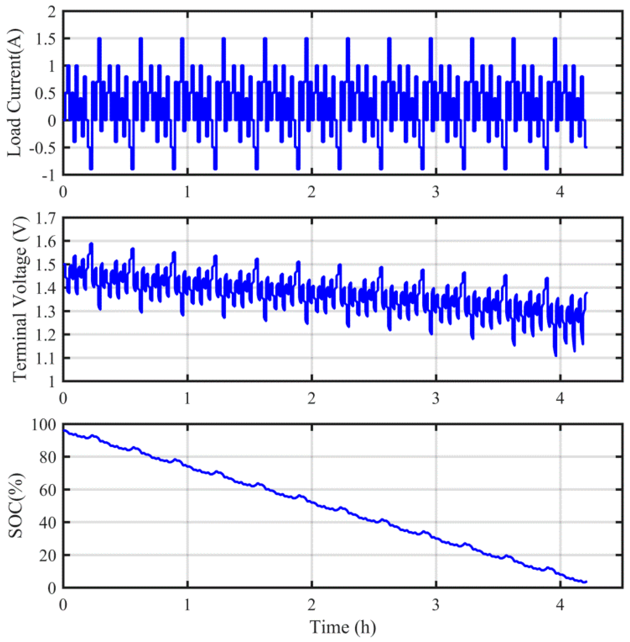
Using the aforementioned experimental schedule, the capacity of the VRB cell was obtained by leveraging the coulombic counting (CC) method. As the initial SOC was accurately known, the reference SOC could also be easily determined. The measured load current, terminal voltage and calibrated reference SOCs are shown in Figure 2. As such, the proposed method was able to be evaluated with the data obtained.
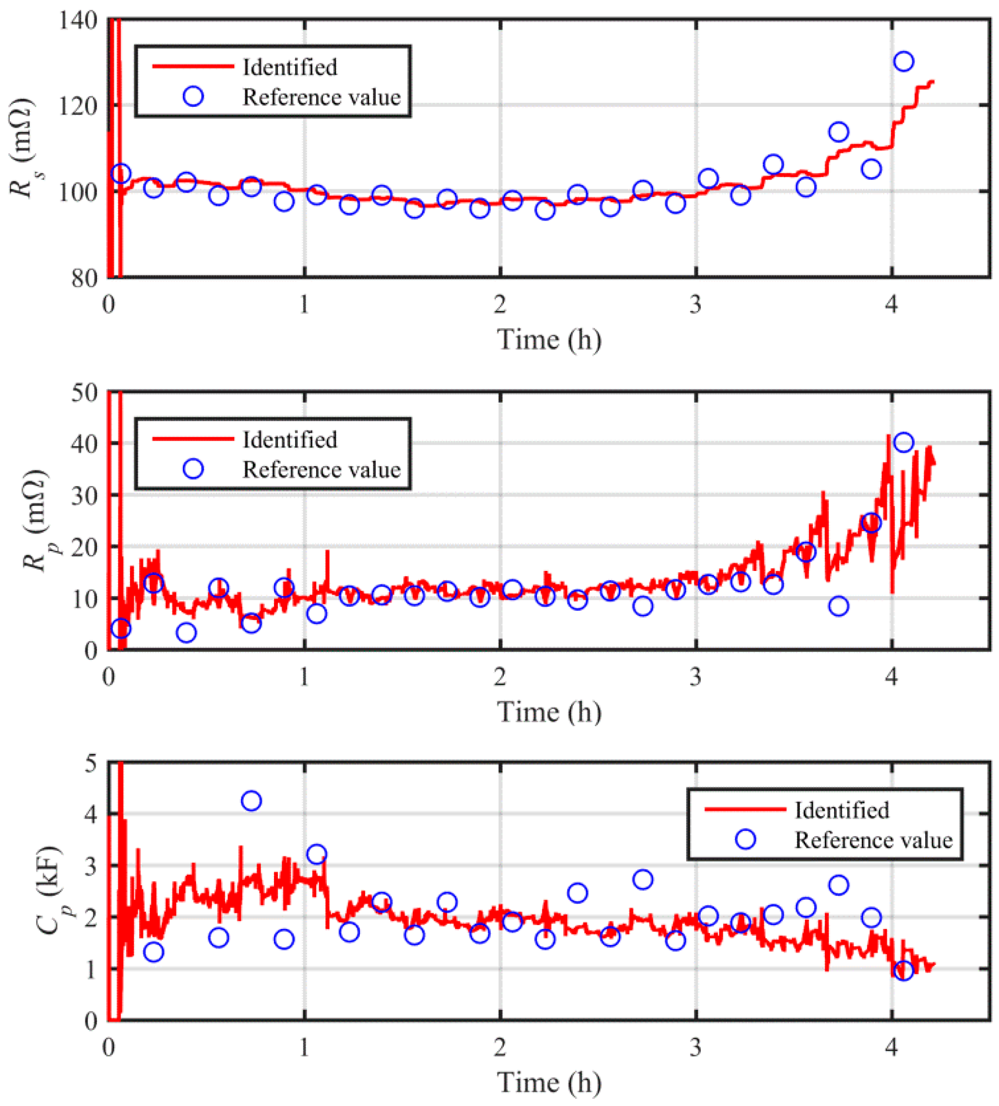
The reference model parameters were also extracted to validate the proposed method. In this work, a user-defined number of time points were selected during the hybrid pulse experiment. Then, around each selected time point, several batches of current/voltage measurements were sampled. Each sampled data batch was leveraged to extract the model parameters offline. Specifically, Rs was calculated by dividing the voltage jump by the corresponding current change. As accurate knowledge of OCV was available from the reference values of the SOC, Rp and Cp were readily determined by fitting the predicted terminal voltages to real measurements.

4.2. Validation of Model Parameter Identification

Identification of model parameters is a prerequisite of accurate modeling and model-based estimation. In this section, validation of the proposed method is discussed for model identification by using the data obtained from the hybrid pulse experiment, as described in Section 4.1.
The online identified model parameters associated with the corresponding reference values are shown in Figure 3. In this figure, the reference values of the model parameters are highly dynamic during the entire experiment. This can be explained by the fact that the model parameters are sensitive to both SOC and current magnitude/direction. The real-time adaption of them is thereby paramount to ensure high modeling and estimation accuracy. By using the proposed method, the erroneously initialized model parameters converged quickly after a short period of initial offset correction. The proposed method was then able to follow the change of model parameters effectively. The proposed method hence manifests itself with the capability to learn the measured current and voltage and to online adapt the model parameters.
With the online adapted model parameters, the modeling results are shown in Figure 4. In this figure, the terminal voltage of the VRB can be predicted accurately with the online adapted model. The predicting error on the terminal voltage is confined well to the 10 mV error bound most of the time, although the error enlarges to some extent in the low SOC region, but can still be kept within 20 mV. The mean absolute error (MAE) and rooted mean square error (RMSE) of the voltage prediction are listed in Table 2. The low modeling error further confirms the accuracy of the identified model parameters, and provides the basis for accurate model-based estimation.

4.3. Validation of SOC Estimation

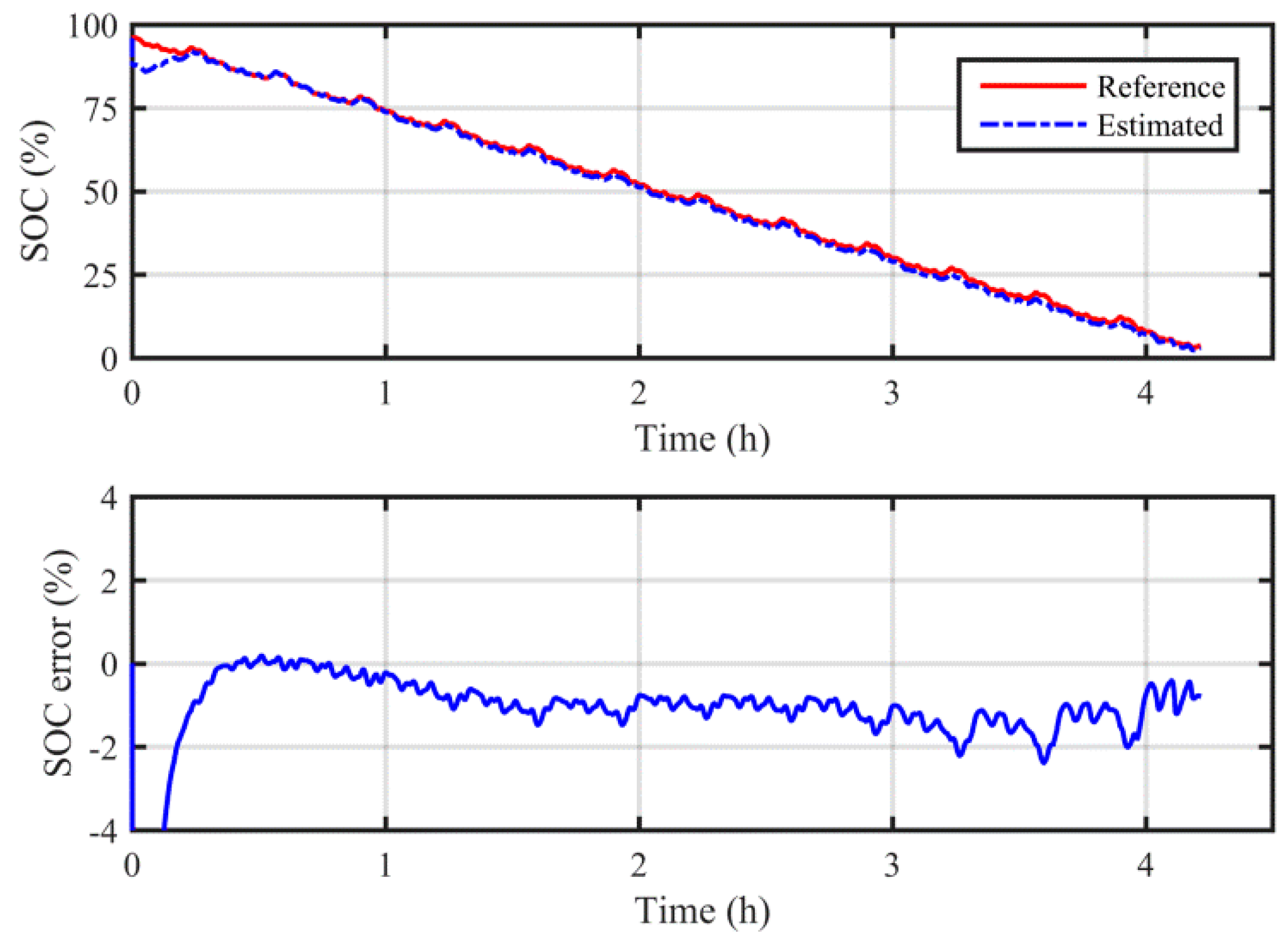
Leveraging the online adapted model, the SOC of the VRB was estimated using the HIF. The results of the SOC estimation are shown in Figure 5. In spite of the large initialization error of the SOC, the proposed method was able to converge to the reference SOC rapidly and keep track of the evolving SOC with high precision. Throughout the experiment, it was observed that the maximum absolute error did not exceed 2.3%. The MAE and RMSE of the SOC estimation are summarized in Table 2. Although the additional open-circuit cell was not used, Table 2 shows that the SOC of the VRB can still be estimated accurately via the proposed method. The proposed method is thereby shown to be highly robust against erroneous initialization and highly reliable in the estimation of VRB SOC.

4.4. Validation of Capacity Decay Monitoring

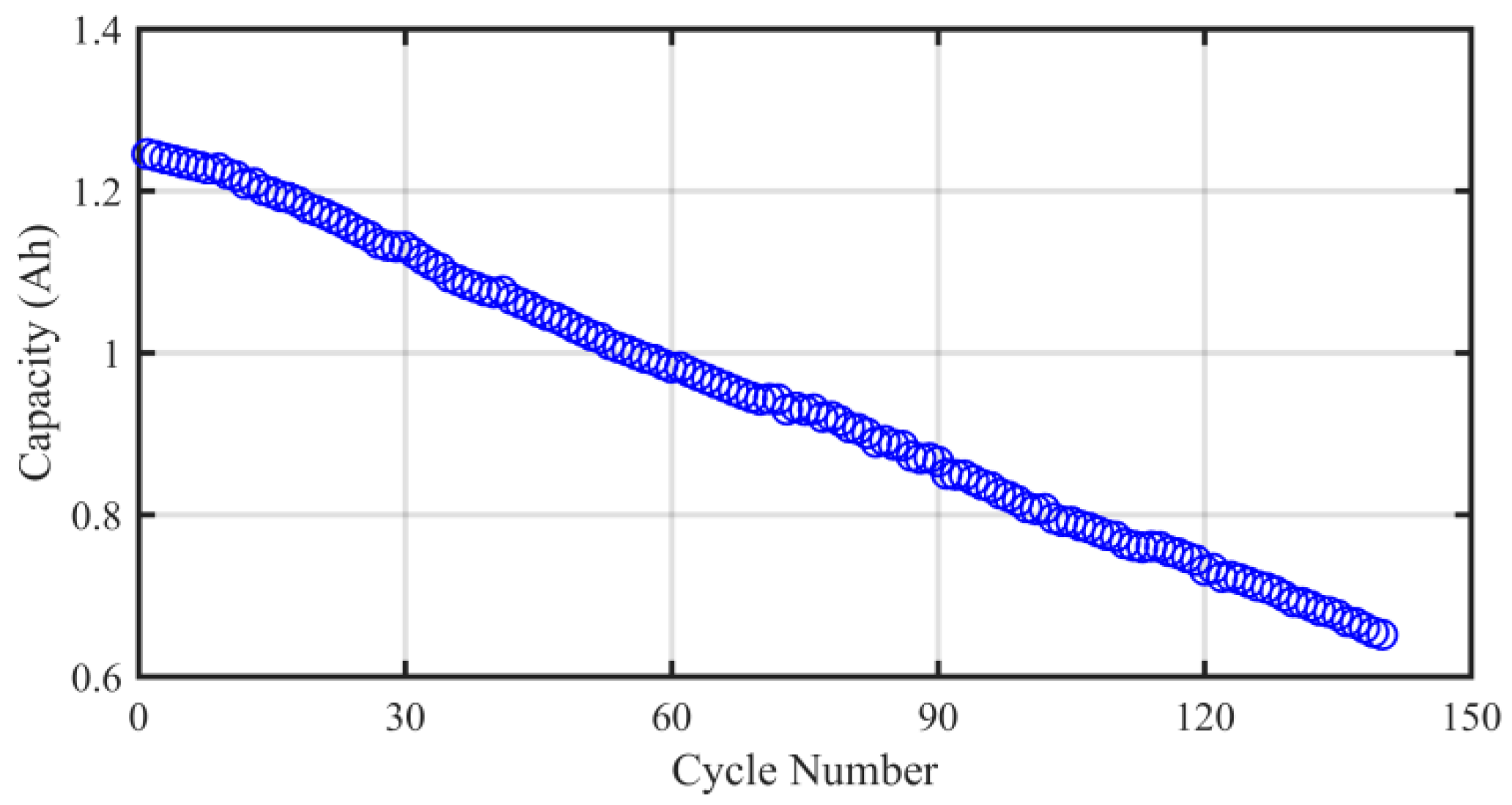
After the hybrid pulse experiment explained in Section 4.1 was performed, a capacity decay test—including 140 cycles of charge and discharge—was carried out to introduce a decay to the VRB’s capacity. The test of capacity decay was performed under a constant current of 1 A for both charge and discharge, while the upper and lower cut-off voltage were defined as 1.65 V and 0.9 V, respectively. The capacity decay of the VRB cell is illustrated in Figure 6, where a significant capacity drop may be observed.
A potentiometric titration was also performed to measure imbalance in vanadium concentrations and oxidation states between the two half-cells. Specifically, 1 mL of electrolyte from each reservoir was sampled after the 140th cycle when the SOC was 23.7%. The results showed that the SOCs were 76.42% and 14.29% for the positive and negative electrolytes, respectively. Moreover, the concentrations of the vanadium species for the positive and negative electrolytes were 2.01 M and 1.02 M, respectively. This finding further confirms a substantial imbalance of vanadium species, which explains the capacity loss of the VRB.
Online monitoring of the imbalance and capacity decay was important for determining a suitable time for rebalancing the two half-cells. In this paper, the hybrid pulse experiment described in Section 4.1 was performed again after the cycling so as to evaluate the performance of the proposed method for capacity decay monitoring.
The results of the capacity decay estimation of the VRB are illustrated in Figure 7. As can be observed in the figure, the estimated capacity is able to converge with the reference capacity following incorrect initialization for the experiment before cycling. Although the initial stage shows an overshoot, the estimation tends to stabilize gradually around the reference value. Meanwhile, the estimation shows a similar performance after the cycling experiment, although a large imbalance of both vanadium species and bulk solution occurred. Rooted in the accurate real-time estimation of capacity, the capacity decay of the studied VRB cell from 1248.5 mAh to 646.4 mAh was monitored accurately. This is insightful for real application, as knowledge of capacity decay helps the operator to determine when to start the rebalancing process to recover the capacity.
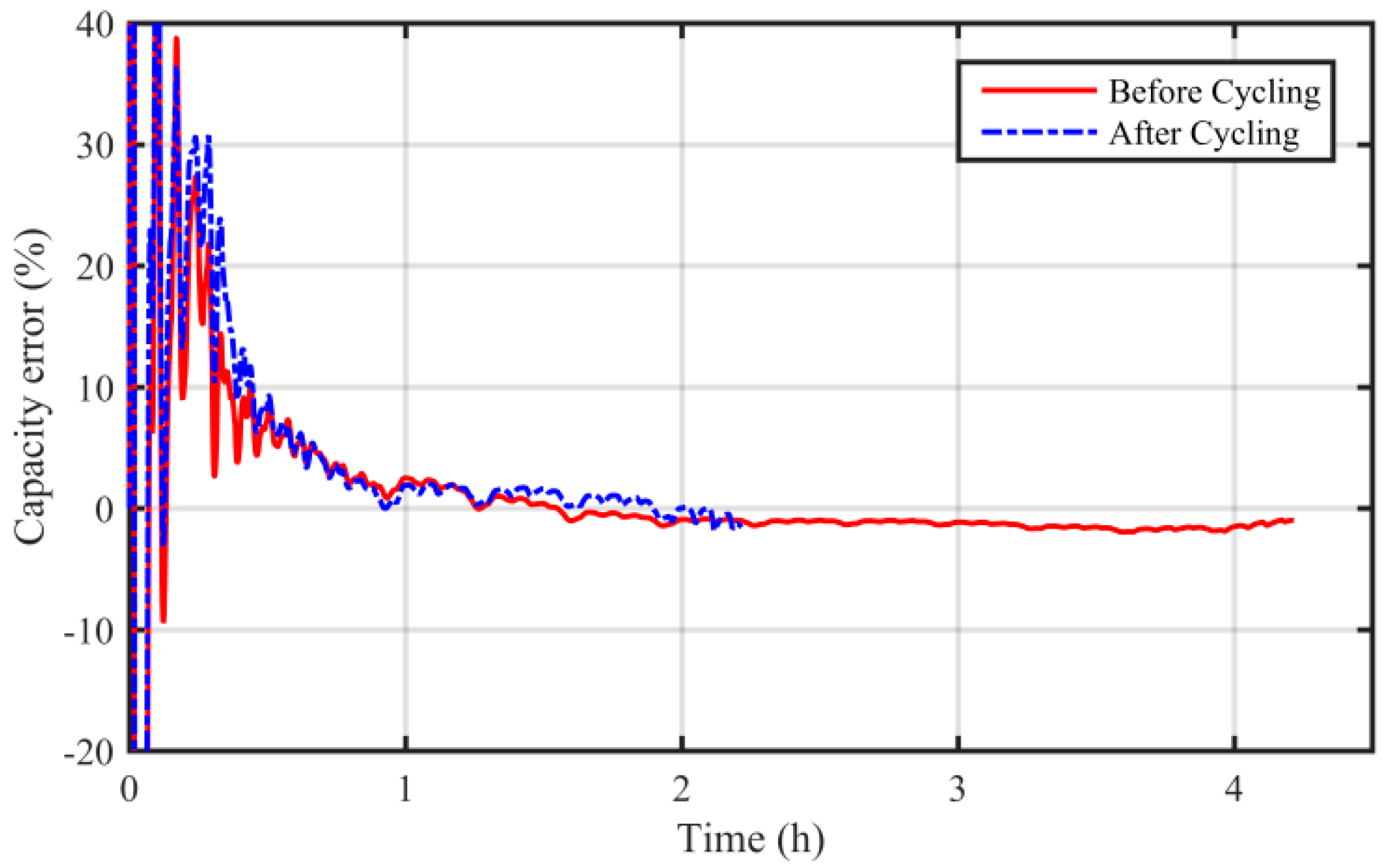
The relative error of capacity estimation for the experiment before and after cycling is shown in Figure 8. As can be observed, the estimation error oscillates at the initial stage to correct the initialization error; as time evolves, the estimation converges to a steady state with reasonable accuracy. The MAE, RMSE and convergence time of the estimation are summarized in Table 3. Note that the estimation converges once the relative estimation error enters the 10% error bound. Importantly, the errors were calculated only after the algorithm converges, as the initial converging process introduces unreasonably high error.
Table 3 shows that the proposed method takes longer to converge compared to the SOC estimate. However, this will not affect real application of the method for two reasons. Firstly, the capacity change is quite slow in real-world VRB systems; thus, the convergence time can be neglected considering the long monitoring period. Secondly, the convergence is actually counted by the calculated steps. The frequency of signal sampling and calculation can be much higher in typical real-time embedded systems. In this case, convergence will likely occur within several seconds.

4.5. Discussion

In this study, we found that the capacity of the VRB dropped significantly within 140 cycles. Two reasons exist for the fast capacity loss. Firstly, the volume of electrolytes was quite small, so that the diffusion-induced imbalance across the membrane easily decreased the overall capacity. Secondly, the differential pressure drop across the membrane was not controlled during the lab-scale experiments. Hence, the rapid capacity loss observed was an extreme case for a lab-scale investigation, and is not typical for VRB systems in practical applications. Commercial VRB systems generally lower the pressure across the membrane to an expected level via effective control of the flow rate; thus, the capacity decay is much slower than that observed in this paper.
The proposed estimation method relies on a computationally affordable circuit model. By lumping together multiple electrical components to describe the dynamics with different time constants, the proposed model associated with the estimator has good potential for use in large VRB systems.

4.6. Future Work

Temperature has a large impact on the performance of VRBs. Thermal precipitation of V5+ occurs if the temperature rises above 40 °C for typical electrolytes with 1.8–2 M vanadium sulfate in 2.5–3 M sulfuric acid, while temperature below 5 °C leads to the precipitation of V2+/V3+ [38]. As our model has not been validated for describing such thermal effects, the performance of the proposed model-based estimator will decline under such unsuitable temperatures. However, in real applications, the electrolytes are typically controlled within a specific temperature range in order for the VRB to work efficiently. In our future work, a refined model which describes the temperature effect will be established and combined with the proposed method to estimate the SOC and capacity decay. This will endeavor to maintain the fidelity of monitoring in the case of unsuitable operating temperatures.
The capacity decay outlined in this paper is mostly due to the imbalance of half-cell electrolytes, which is rooted in the diffusion of vanadium species and water across the separator. Nevertheless, additional irreversible capacity decay, including that caused by side effects, passivation, and air oxidation, was not analyzed in this paper. More experiments will need to be performed to further validate the proposed method for monitoring such irreversible capacity decay in the future.

5. Conclusions

This paper proposes a novel method for monitoring the SOC and capacity decay of a VRB, which was based on an online adapted battery model. RTLS was employed to compensate for the noise effect and online identify the unbiased model parameters. Leveraging the online identified model, an HIF-based joint observer was proposed to co-estimate the SOC and capacity decay of a VRB. Experiments were performed to validate the proposed method. Results showed that the proposed method was able to accurately track the change of model parameters under the impact of noise disturbances. The online unbiased model parameterization further ensured a high modeling accuracy. The SOC estimate was found to be within a 2.3% error bound, while the capacity decay from 1248.5 mAh to 646.4 mAh was also monitored accurately.
The proposed method observes the states of interest by making use of the measured onboard current and voltage data, as well as avoiding the need to install open-circuit cells, which increases the complexity and cost of the overall system. Hence, the method appears to be a good candidate for the management of VRB systems.

Author Contributions

Conceptualization, S.M. and Y.Y.; methodology, S.M. and B.X.; validation, S.M. and T.L.; formal analysis, S.M. and B.X.; investigation, S.M. and B.X.; resources, T.M.L.; writing—original draft preparation, S.M.; writing—review and editing, S.M. and T.L.

Funding

This research received no external funding.

Conflicts of Interest

The authors declare no conflict of interest.

References

  1. Pham, H.T.T.; Kim, Y.; Kim, Y.J.; Lee, J.W.; Park, M.S. Robust design of dual-phasic carbon cathode for lithium–oxygen batteries. Adv. Funct. Mater. 2019, 29, 1902915. [Google Scholar] [CrossRef]
  2. Sum, E.; Rychcik, M.; Skyllas-Kazacos, M. Investigation of the V (V)/V (IV) system for use in the positive half-cell of a redox battery. J. Power Source 1985, 16, 85–95. [Google Scholar] [CrossRef]
  3. Skyllas-Kazacos, M.; Rychcik, M.; Robins, R.G.; Fane, A.; Green, M. New all-vanadium redox flow cell. J. Electrochem. Soc. 1986, 133, 1057. [Google Scholar] [CrossRef]
  4. Zeng, Y.; Zhao, T.; An, L.; Zhou, X.; Wei, L. A comparative study of all-vanadium and iron-chromium redox flow batteries for large-scale energy storage. J. Power Source 2015, 300, 438–443. [Google Scholar] [CrossRef]
  5. Zeng, Y.; Li, F.; Lu, F.; Zhou, X.; Yuan, Y.; Cao, X.; Xiang, B. A hierarchical interdigitated flow field design for scale-up of high-performance redox flow batteries. Appl. Energy 2019, 238, 435–441. [Google Scholar] [CrossRef]
  6. Shi, Y.; Eze, C.; Xiong, B.; He, W.; Zhang, H.; Lim, T.; Ukil, A.; Zhao, J. Recent development of membrane for vanadium redox flow battery applications: A review. Appl. Energy 2019, 238, 202–224. [Google Scholar] [CrossRef]
  7. Kim, K.J.; Park, M.-S.; Kim, Y.-J.; Kim, J.H.; Dou, S.X.; Skyllas-Kazacos, M. A technology review of electrodes and reaction mechanisms in vanadium redox flow batteries. J. Mater. Chem. A 2015, 3, 16913–16933. [Google Scholar] [CrossRef]
  8. Zhang, X.; Li, Y.; Skyllas-Kazacos, M.; Bao, J. Optimal sizing of vanadium redox flow battery systems for residential applications based on battery electrochemical characteristics. Energies 2016, 9, 857. [Google Scholar] [CrossRef]
  9. Skyllas-Kazacos, M.; Kazacos, M. State of charge monitoring methods for vanadium redox flow battery control. J. Power Source 2011, 196, 8822–8827. [Google Scholar] [CrossRef]
  10. Li, X.; Xiong, J.; Tang, A.; Qin, Y.; Liu, J.; Yan, C. Investigation of the use of electrolyte viscosity for online state-of-charge monitoring design in vanadium redox flow battery. Appl. Energy 2018, 211, 1050–1059. [Google Scholar] [CrossRef]
  11. Wei, Z.; Zou, C.; Leng, F.; Soong, B.H.; Tseng, K.-J. Online model identification and state-of-charge estimate for lithium-ion battery with a recursive total least squares-based observer. IEEE Trans. Ind. Electron. 2017, 65, 1336–1346. [Google Scholar] [CrossRef]
  12. Li, Y.; Vilathgamuwa, M.; Farrell, T.; Choi, S.S.; Tran, N.T.; Teague, J. A physics-based distributed-parameter equivalent circuit model for lithium-ion batteries. Electrochim. Acta 2019, 299, 451–469. [Google Scholar] [CrossRef]
  13. Cui, X.; He, Z.; Li, E.; Cheng, A.; Luo, M.; Guo, Y. State-of-charge estimation of power lithium-ion batteries based on an embedded micro control unit using a square root cubature Kalman filter at various ambient temperatures. Int. J. Energy Res. 2019. [Google Scholar] [CrossRef]
  14. Lee, J.; Kim, J.; Park, H. Numerical simulation of the power-based efficiency in vanadium redox flow battery with different serpentine channel size. Int. J. Hydrog. Energy 2019. [Google Scholar] [CrossRef]
  15. Shah, A.A.; Al-Fetlawi, H.; Walsh, F.C. Dynamic modelling of hydrogen evolution effects in the all-vanadium redox flow battery. Electrochim. Acta 2010, 55, 1125–1139. [Google Scholar] [CrossRef]
  16. Al-Fetlawi, H.; Shah, A.A.; Walsh, F.C. Modelling the effects of oxygen evolution in the all-vanadium redox flow battery. Electrochim. Acta 2010, 55, 3192–3205. [Google Scholar] [CrossRef] [Green Version]
  17. Tang, A.; Bao, J.; Skyllas-Kazacos, M. Studies on pressure losses and flow rate optimization in vanadium redox flow battery. J. Power Source 2014, 248, 154–162. [Google Scholar] [CrossRef]
  18. Chahwan, J.; Abbey, C.; Joos, G. VRB modelling for the study of output terminal voltages, internal losses and performance. In Proceedings of the IEEE Canada Electrical Power Conference, Montreal, QC, Canada, 25–26 October 2007; pp. 387–392. [Google Scholar]
  19. Barote, L.; Marinescu, C.; Georgescu, M. VRB modeling for storage in stand-alone wind energy systems. In Proceedings of the 2009 IEEE Bucharest Power Tech, Bucharest, Romania, 28 June–2 July 2009; pp. 1–6. [Google Scholar]
  20. Barote, L.; Marinescu, C. A new control method for VRB SOC estimation in stand-alone wind energy systems. In Proceedings of the 2009 International Conference on Clean Electrical Power, Capri, Italy, 9–11 June 2009; pp. 253–257. [Google Scholar]
  21. Wei, Z.; Tseng, K.J.; Wai, N.; Lim, T.M.; Skyllas-Kazacos, M. Adaptive estimation of state of charge and capacity with online identified battery model for vanadium redox flow battery. J. Power Source 2016, 332, 389–398. [Google Scholar] [CrossRef]
  22. Wei, Z.; Zhao, J.; Ji, D.; Tseng, K.J. A multi-timescale estimator for battery state of charge and capacity dual estimation based on an online identified model. Applied Energy 2017, 204, 1264–1274. [Google Scholar] [CrossRef]
  23. Wei, Z.; Bhattarai, A.; Zou, C.; Meng, S.; Lim, T.M.; Skyllas-Kazacos, M. Real-time monitoring of capacity loss for vanadium redox flow battery. J. Power Source 2018, 390, 261–269. [Google Scholar] [CrossRef]
  24. Zhang, Y.; Zhao, J.; Wang, P.; Skyllas-Kazacos, M.; Xiong, B.; Badrinarayanan, R. A comprehensive equivalent circuit model of all-vanadium redox flow battery for power system analysis. J. Power Source 2015, 290, 14–24. [Google Scholar] [CrossRef]
  25. Mohamed, M.R.; Ahmad, H.; Seman, M.N.A.; Razali, S.; Najib, M.S. Electrical circuit model of a vanadium redox flow battery using extended Kalman filter. J. Power Source 2013, 239, 284–293. [Google Scholar] [CrossRef]
  26. Xiong, B.; Zhao, J.; Wei, Z.; Skyllas-Kazacos, M. Extended Kalman filter method for state of charge estimation of vanadium redox flow battery using thermal-dependent electrical model. J. Power Source 2014, 262, 50–61. [Google Scholar] [CrossRef]
  27. Xiong, B.; Zhao, J.; Su, Y.; Wei, B.; Skyllas-Kazacos, M. State of Charge estimation of vanadium redox flow battery based on sliding mode observer and dynamic model including capacity fading factor. IEEE Trans. Sustain. Energy 2017, 8, 1658–1667. [Google Scholar] [CrossRef]
  28. Sun, C.; Chen, J.; Zhang, H.; Han, X.; Luo, Q. Investigations on transfer of water and vanadium ions across Nafion membrane in an operating vanadium redox flow battery. J. Power Source 2010, 195, 890–897. [Google Scholar] [CrossRef]
  29. Corcuera, S.; Skyllas-Kazacos, M. State-of-charge monitoring and electrolyte rebalancing methods for the vanadium redox flow battery. Eur. Chem. Bull. 2012, 1, 511–519. [Google Scholar]
  30. Tang, A.; Bao, J.; Skyllas-Kazacos, M. Dynamic modelling of the effects of ion diffusion and side reactions on the capacity loss for vanadium redox flow battery. J. Power Source 2011, 196, 10737–10747. [Google Scholar] [CrossRef]
  31. Badrinarayanan, R.; Zhao, J.; Tseng, K.; Skyllas-Kazacos, M. Extended dynamic model for ion diffusion in all-vanadium redox flow battery including the effects of temperature and bulk electrolyte transfer. J. Power Source 2014, 270, 576–586. [Google Scholar] [CrossRef]
  32. Agar, E.; Benjamin, A.; Dennison, C.; Chen, D.; Hickner, M.; Kumbur, E. Reducing capacity fade in vanadium redox flow batteries by altering charging and discharging currents. J. Power Source 2014, 246, 767–774. [Google Scholar] [CrossRef]
  33. Skyllas-Kazacos, M.; Goh, L. Modeling of vanadium ion diffusion across the ion exchange membrane in the vanadium redox battery. J. Membr. Sci. 2012, 399, 43–48. [Google Scholar] [CrossRef]
  34. Wei, Z.; Zhao, J.; Xiong, R.; Dong, G.; Pou, J.; Tseng, K.J. Online estimation of power capacity with noise effect attenuation for lithium-ion battery. IEEE Trans. Ind. Electron. 2018, 66, 5724–5735. [Google Scholar] [CrossRef]
  35. Wei, Z.; Meng, S.; Xiong, B.; Ji, D.; Tseng, K.J. Enhanced online model identification and state of charge estimation for lithium-ion battery with a FBCRLS based observer. Applied Energy 2016, 181, 332–341. [Google Scholar] [CrossRef]
  36. Xia, B.; Zhang, Z.; Lao, Z.; Wang, W.; Sun, W.; Lai, Y.; Wang, M. Strong tracking of a H-infinity filter in lithium-ion battery state of charge estimation. Energies 2018, 11, 1481. [Google Scholar] [CrossRef]
  37. Wei, Z.; Lim, T.M.; Skyllas-Kazacos, M.; Wai, N.; Tseng, K.J. Online state of charge and model parameter co-estimation based on a novel multi-timescale estimator for vanadium redox flow battery. Appl. Energy 2016, 172, 169–179. [Google Scholar] [CrossRef]
  38. Kazacos, M.; Cheng, M.; Skyllas-Kazacos, M. Vanadium redox cell electrolyte optimization studies. J. Appl. Electrochem. 1990, 20, 463–467. [Google Scholar] [CrossRef]
Figure 1. General structure of the N-th order RC model (the ellipsis represents repeated RC branches connected in series).
Energies 12 03005 g001
Figure 2. Measured load current, terminal voltage and calibrated state of charge (SOC) of the hybrid pulse experiment.
Energies 12 03005 g002
Figure 3. Results of model parameter identification with the proposed method.
Energies 12 03005 g003
Figure 4. Results of the terminal voltage prediction with the online adapted model.
Energies 12 03005 g004
Figure 5. Results of SOC estimation with the proposed method.
Energies 12 03005 g005
Figure 6. Capacity decay of the vanadium redox flow battery (VRB) cell during long-term cycling.
Energies 12 03005 g006
Figure 7. Monitoring results of capacity decay with the proposed method.
Energies 12 03005 g007
Figure 8. Relative error of capacity estimation with the proposed method (the 0% line means perfect estimation without error).
Energies 12 03005 g008
Table 1. Procedures for adopting the H-infinity filter.
Define: A ^ k = f x | x k = x ^ k + , C ^ k = g x | x k = x ^ k +
Initialization: x ^ 0 + , R x , 0 + , Rw, Rv, S0, τFor k = 1, 2, …
Priori state update: x ^ k = f ( x ^ k 1 + , u k 1 )
Priori error covariance update: R x , k = A ^ k 1 R x , k 1 + A ^ k 1 T + R w , k
Update of HIF gain: M k = h k T S k h k L k = A ^ k R x , k ( I τ M k R x , k + C ^ k T R v , k 1 C ^ k R x , k ) 1 C ^ k T R v , k 1
Posteriori state update: x ^ k + = x ^ k + L k [ y k g ( x ^ k , u k ) ]
Posteriori error covariance update: R x , k + = R x , k ( I τ M k R x , k + C ^ k T R v , k 1 C ^ k R x , k ) 1
Table 2. Performance of the proposed method on voltage prediction and SOC estimation for the hybrid pulse experiment.
MeasureVoltage PredictionSOC Estimation
MAE1.60 mV1.15%
RMSE2.03 mV1.65%
MAE, mean absolute error; RMSE, root mean square error.
Table 3. Performance of the proposed method on voltage prediction and SOC estimation for the hybrid pulse experiment.
MeasureBefore CyclingAfter Cycling
MAE1.73%2.33%
RMSE2.16%3.33%
Convergent time1305 steps1389 steps