Article

IoT and Blockchain Paradigms for EV Charging System

1
DCTI, Instituto Universitário de Lisboa (ISCTE-IUL), ISTAR-IUL, 1649-026 Lisboa, Portugal
2
INOV INESC Inovação—Instituto de Novas Tecnologias, 1000-029 Lisboa, Portugal
3
ALGORITMI Research Centre, University of Minho, 4800-058 Guimarães, Portugal
4
CMEMS-UMinho Center, University of Minho, 4800-058 Guimarães, Portugal
*
Author to whom correspondence should be addressed.
Energies 2019, 12(15), 2987; https://doi.org/10.3390/en12152987
Submission received: 13 June 2019 / Revised: 23 July 2019 / Accepted: 31 July 2019 / Published: 2 August 2019
(This article belongs to the Special Issue Intelligent Transportation Systems for Electric Vehicles)

Abstract

:
In this research work, we apply the Internet of Things (IoT) paradigm with a decentralized blockchain approach to handle the electric vehicle (EV) charging process in shared spaces, such as condominiums. A mobile app handles the user authentication mechanism to initiate the EV charging process, where a set of sensors are used for measuring energy consumption, and based on a microcontroller, establish data communication with the mobile app. A blockchain handles financial transitions, and this approach can be replicated to other EV charging scenarios, such as public charging systems in a city, where the mobile device provides an authentication mechanism. A user interface was developed to visualize transactions, gather users’ preferences, and handle power charging limitations due to the usage of a shared infrastructure. The developed approach was tested in a shared space with three EVs using a charging infrastructure for a period of 3.5 months.

Graphical Abstract

1. Introduction

One of the big challenges related with electric vehicle (EV) market penetration is the charging process, where the main problems are related to the lack of proper infrastructure in residential buildings (condominiums) since they are not prepared for this new reality. Condominiums have the problem of shared electricity, which does not meet the EV owner’s requirements. Based on new advances in the Internet of Things (IoT) [1], and the associated sensing devices and communication platforms, blockchain and information systems have the potential to create new solutions for these problems. Another facet of this challenge is the problem associated with rental houses and the eventual need for supporting EV charging in these cases.
In condominiums, unfortunately, there is a general reluctance regarding the installation of EV charging stations that will only be used by a few homeowners [2]. In addition, there is also an issue regarding the safety of the electrical installations, since they are not built proactively to support EV charging stations, and, adapting the condominium electrical infrastructure will require not only that a consensus between the majority of the owners is reached, which may be hard to achieve, but also authorizations issued by the government building safety entities.
Taking into consideration that most residential buildings have shared spaces with common electrical installations and are not prepared for the installation of new EV charging systems, this is a barrier to EV uptake [3]. A study by Lopez-Behar et al. [4] identified four main problem domains in the context of sharing EV charging solutions in buildings: unavailable charging infrastructure, building limitations, regulation issues and parking availability.
In this work, we propose a new IoT-based approach for handling the EV charging process, which can be used in the context of a shared energy infrastructure without requiring a supervision entity to control the process.
The proposed solution is supported by a decentralized blockchain approach, running on a mobile device app. Figure 1 shows an overview of a condominium with the proposed EV charging platform. This work allows the following features: (1) A pre-registration with a local EV charging provider is not required, avoiding the problem of different cards in different charging infrastructures (every charging infrastructure has its own cards, and this is a problem for EV owners because they need several charging cards when different providers are available); (2) it can work with digital currency using a peer-to-peer (P2P) framework on the same homogeneous blockchain infrastructure and technology; and (3) reduced cost (almost zero fees), because there is no requirement for a third party management entity, apart from the condominium, which would create additional costs.
As illustrated in Figure 1, the major features of the proposed system are: (1) User authentication with a mobile device using Bluetooth Low Energy (BLE) communication and, based on this, release of energy for the EV charging process; and (2) energy consumption is monitored by Internet of Things (IoT) sensors and a microcontroller board transmits the data to a web server (Raspberry Pi with Raspbian operating system), which acts as the management unit, storing the data, handling the transactions in a blockchain implementation and managing the charging according to the power limitations.
Complementary to the setup presented in Figure 1, which is suitable for deploying the solution at the local level, in the context of a single condominium, an equivalent model can be applied to scale the solution to a wider geographical area with an increased number of charging locations. In this sense, Figure 2 expands the proposed model to an IoT architecture that is suitable to explore cloud paradigms, such as Infrastructure as a Service (IaaS) or Software as a Service (SaaS), where the local management unit is replaced by a shared cloud computing platform. Without loss of generality and instantiating the model with existing platforms, the mobile app can be deployed on the Google Play store or Apple’s App Store, the Management Unit can be packaged in a Docker container [5], and deployed on the AWS (Amazon Web Services) cloud computing platform, and the Ethereum open blockchain network can be used to support the financial transactions originated by the EV charging operation.
Figure 2 also enumerates the sequence steps to initiate a charging process: (1) Using the internet connection, the payment is sent from the mobile device to the open blockchain network (Ethereum); (2) the information related to the operation is exchanged between the mobile device and the Management Unit hosted on the AWS; (3) payment is received from the blockchain network, triggering the charging process on the Management Unit; and (4) the EV charging process is enabled on the IoT device (installed on the parking facilities), and the information related to the energy being delivered is sent back to the Management Unit on the AWS.
This paper is organized as follows. Section 2 presents the state of the art in related work. An overview of the proposed approach is presented in Section 3, and Section 4 describes the system implementation. Section 5 presents a case study at a condominium, and Section 6 discusses future implications of the presented work. Finally, Section 7 presents the conclusions.

2. State of the Art

The proposed approach explores a set of works in several domain areas to create a new approach to handle the EV charging process in shared spaces, including the use of IoT sensing information to measure electricity taken on the EV charging process. Concerning driver profiles and EV charging with power limitations, several studies have been performed, and we apply an approach based on our previous work described in [6]. In our implementation, it was also considered an implicit authentication mechanism [7], applied on user’s mobile devices, which confirms the user authentication based on actions that he had performed on a daily basis. This implicit authentication mechanism can be used to prevent fraudulent credit transactions on a mobile device, verifying that the user is who he claims to be during the transaction. After researching systems that meet our criteria, we found some promising work [8,9,10,11,12]. We apply a solution with user privacy (no identification is performed) in an approach based on the system proposed by Frank et al., called Touchalytics [13]. We also apply the blockchain approach to handle distributed transactions without central supervision. The primary goal of the blockchain is to allow decentralized transactions with a digital currency, such as Bitcoin [14] or Etherum [15], without the need of a public authority to control the process. From the technical perspective, a blockchain is a sequence of blocks associated with transactional data using encryption based on a private and public key [16]. User A performs a transaction, and this process is associated with a block encrypted with his private key, in a hash process. User B checks the transaction using the public key of user A, allowing the following properties:
  • Decentralization, since we need confirmation from some party of each block transaction without central control;
  • Anonymity, since it allows for the authentication of transactions without giving up any personal information;
  • Auditability, which is performed based on the fact that each of the transactions is recorded and validated with a timestamp, where users can trace the previous transactions by accessing any node in the distributed network.
The application of blockchain in the domain of smart grids has great potential, providing a decentralized approach to implement management systems [17] and handle power transactions. Due to the large space occupied by the meter sampling information on a blockchain block, [17] presents a design to balance the amount of information kept onchain/offchain while keeping the properties of a block chain implementation. The authors of [18] note the use of an open public cryptocurrency network, such as Bitcoin or Ethereum, can introduce a high transactional cost, due to the fees associated with cryptocurrency transaction processing (eventually similar to the cost of the energy supplied), and propose the development of a private Bitcoin-based blockchain network for EV charging purposes. Other relevant application cases include micro-generation [19,20], as well as the contribution to handle the EV charging payment process without the use of propriety company payment systems.
The EV charging payment process is more frequent than fossil fuel refuelling and more complex due to the immaturity of the service. Specifically, the following issues are fairly common: (1) Transparency and clarity of rates and charges before they are incurred; (2) ability to pick-and-choose best rates and location of available charging points on the go; (3) ability to request priority charging and pay for it, when other EVs do not need priority; (4) ability to select a supplier or source of electricity, which would also enable greater competition and increase trust of customers; and (5) preferences for various types of payment, such as post-paid, pre-paid, or one-off payment.
We complement this work with our previous work on an EV charging system [21,22] and IoT energy measurements using local sensors [23], as well as new challenges of energy markets [19]. Some issues identified are also addressed in [24], which proposes a blockchain-based model with recourse to a bid to identify charging stations (and eventually schedule the charging), complementary to the approach suggested in [21]. Another issue originated by the increase of the EV charging needs is the impact on the energy demands and the power limitation of the existing infrastructure [25], which may not only increase the operational costs to fulfil the required demand, but also affects the voltage stability of the network. In [25], the authors introduced the AdBEV, which is an algorithm to optimize the EV charging schedule, maximizing the voltage stability at the power grid side, and minimizing the charging costs. In [26] the application of a blockchain-based process is suggested to support the EV charging queue management.
Together with mobile device authentication and a payment system, we developed a new approach to be used in shared EV charging spaces. Another interesting output is to use mobile devices to provide authentication and payment services in the context of the public EV charging systems, exploring recent advances in mobile device payment systems for public transportation [27] and other application areas [28]. As a new topic of research, new publications are appearing in the literature concerning the use of a blockchain approach to handling the EV charging process, such as: testing pilots to use digital currency for the EV charging process [29,30]; proposal of a P2P energy transaction model to handle the EV vehicle-to-grid (V2G) operation in smart grids [31]; handling the EV authentication issues based on a blockchain approach [32]; proposal of a cross-domain authentication scheme with blockchain [33]; and handling of security and privacy issues for energy transactions based on blockchain. Moreover, in this context, the EV is identified as part of the energy market [34], and as a contribution to the contextualization of the local energy market [35], where the blockchain plays an important role in the decentralization process, as well as for optimization purposes [36].

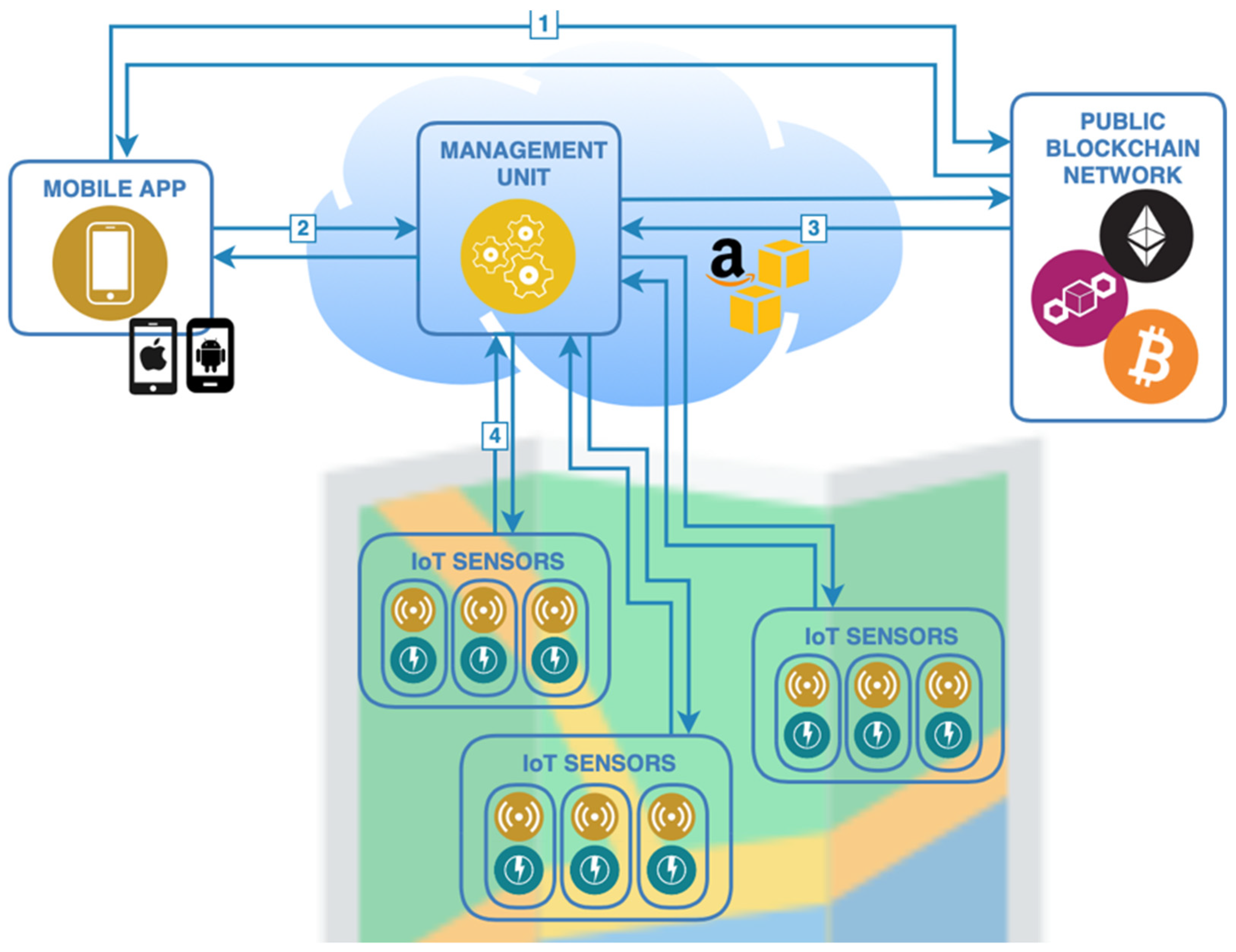
3. Proposed Approach—Conceptual Model

The EV charging platform is composed of the elements presented in Figure 3, whose roles are briefly described below, and the implementation details for each component is detailed in the next section:
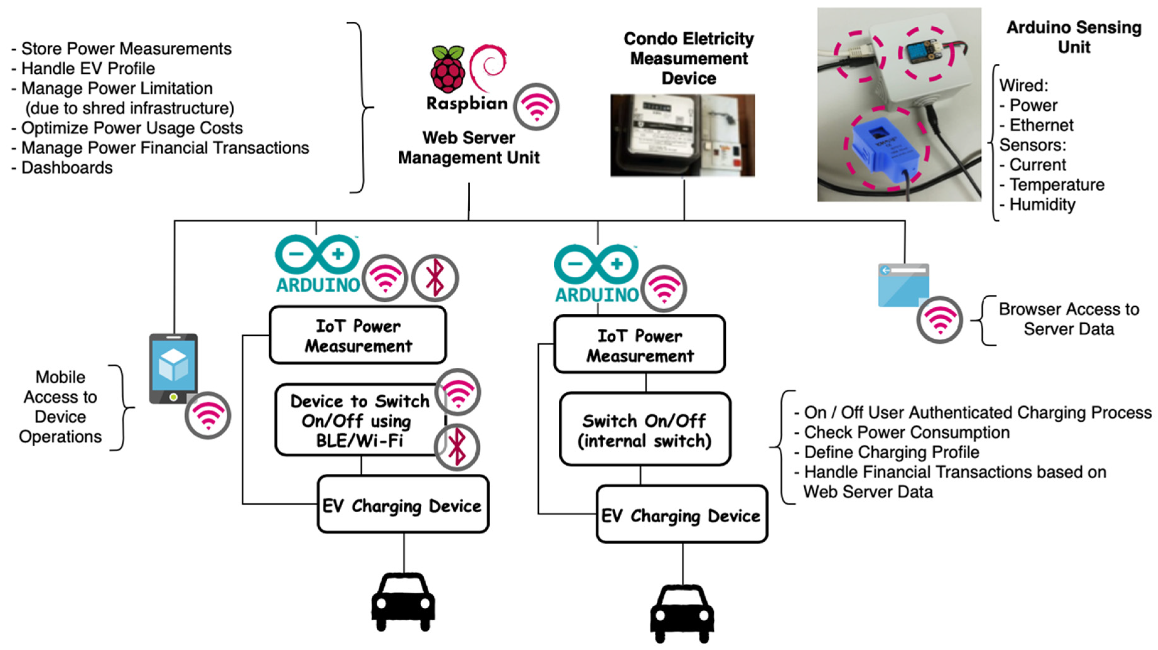
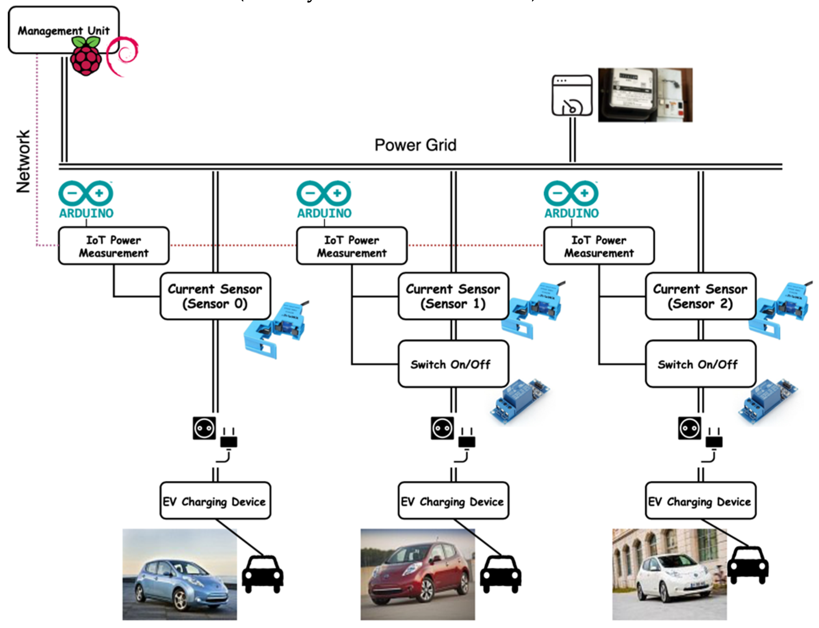
  • IoT Units. Sensor and power management units that support the interaction with the EV charger, being used to enable or disable it (on/off switch), to measure the amount of power consumed, gather environment temperature and humidity (complementary measures), and to upload all the information to the management unit. Implemented with COTS (commercial off-the-shelf) components, Arduino microcontrollers, actuators and sensors. Depending on the installation requirements, different components can be combined to set up the IoT Unit.
  • Mobile App. The element that establishes the interaction between the EV owner and the platform, authenticates the user, starts/stops the charging process, and provides some common operations, such as configuration management, usage dashboards, transactions lists, etc.
  • Management Unit. This element is the heart of the platform, providing not only all the backend services to support the required operations, but also the management console for the platform. In the prototype presented in this paper, the management unit was implemented using a Raspberry Pi, which also acts as a Wi-Fi access point, providing network access to the sensor units and to the mobile app, but it could also be implemented using a cloud computing platform.

4. System Implementation
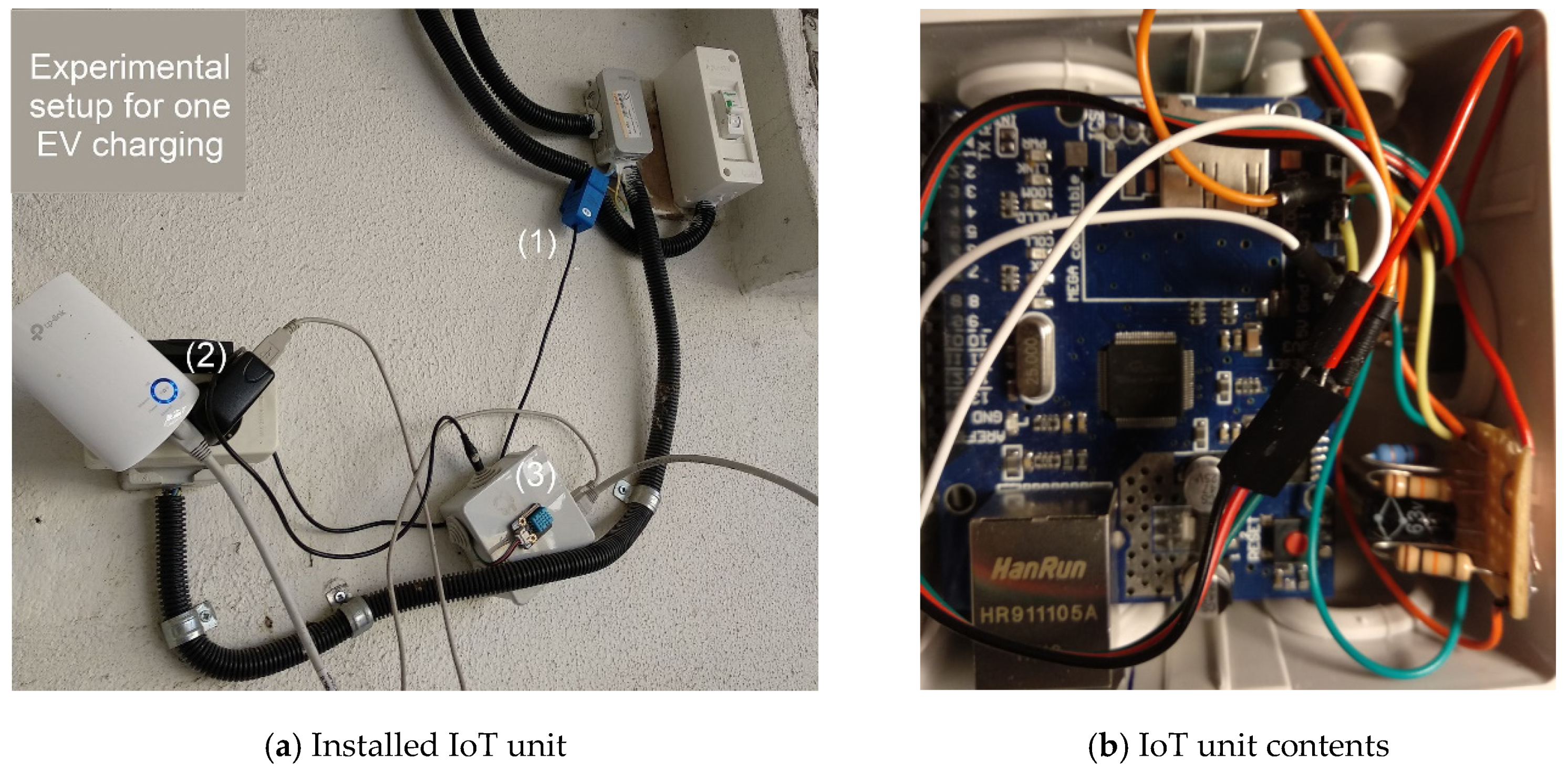
As previously described, the proposed EV charging platform is composed of three major elements: IoT units (sensors/actuators devices), a mobile app and a management unit. This section explores the implementation details of each element.

4.1. IoT Unit

The IoT unit was developed considering the approach described in our previous work [19], with improvements to the hardware and transmission process, as well as the creation of a prototype towards a possible commercial system. The first steps were the assessment of the surrounding environment and context, aiming to review the system design approach. The goal of reaching a potential commercial system’s architecture led to the consideration of a flexible design, where different network transmission requirements/devices, current sensor devices and power switching devices should be available to use, tailoring their combination to match a specific installation requirement. After an initial period of checking and testing hardware, we implemented a solution based on an Arduino Uno (microcontroller) combined with the devices listed in Table 1, where only one component for each type was used to assemble the IoT unit.

4.1.1. Configuration of Variations

Wired (Ethernet) vs. Wireless (Wi-Fi) Network: Taking into account that most existing condominiums do not have a wired network infrastructure, the use of a Wi-Fi network simplifies the deployment of the platform, as no other infrastructure components are required, particularly when using the Wi-Fi network provided by the management unit. For new installations or for larger installations, a cable-based approach may be more suitable and less error-prone.
Intrusive vs. Non-Intrusive Power Sensing: The non-intrusive approach offers the capability to measure the energy that passed through a specific IoT unit, allowing the measures to be gathered without any major changes to the existing infrastructure, as the sensor only needs to be “hooked” around the power cable that powers the EV charger device socket. However, since no physical devices are installed between the power plug and the EV charging device, the capability to enable/disable the charging process needs to be implemented by the EV or by the charging device and exposed as a service to the charging platform; eventually, the platform network or other communication technologies, like BLE, could allow the management unit to start/stop the process based on user commands. On the other hand, although the intrusive approach forces the platform owner to introduce the IoT device between the power grid and the power socket, which requires some intervention in the existing infrastructure, it is able to provide a sound solution to the platform owner, as it provides a “one-in-a-box” unit that is able to measure and control the energy delivery (enabling/disabling) simultaneously, while providing energy only to authenticated users or inside of a blockchain transactional context.
Built-In vs. COTS (Commercial Off-The-Shelf) Power Switching: To enable/disable the EV charging devices, we have considered using the SRD-05VDC-SL-C (Ningbo Song Relay Co., Ningbo, China) device (see Figure 4f), which, when connected to the Arduino device, can be used as a switch. A different approach to support this requirement is to use a standard TCP/IP-based (Transmission Control Protocol—Internet Protocol) switch commonly available as COTS on the market.

4.1.2. Hardware Components

The most relevant characteristics of the hardware components used for the prototype implementation are:
  • Arduino R3 Uno Microcontroller (Figure 4a): based on the microcontroller ATmega328P, it has the following characteristics (from the Arduino R3 Uno dataset):
    14 digital input/output pins (the first 2 are commonly used for serial RX/TX (Receive and Transmit), 6 can be used as pulse-width modulation (PWM) outputs that mimic an analogue output) and 6 analogue input pins (A0–A6).
    16 MHZ clock speed (memory: flash, 32 K; SRAM, 2 K; EEPROM, 1 K).
    USB type B connection, ICSP Header.
    Power input 9 V (operating voltage 5 V), built-in LED, reset button.
  • Sparkfun Wi-Fi Arduino Shield (based on ESP8266) (Figure 4b): manufactured by Sparkfun this Arduino shield is commonly used to connect the Arduino microcontroller to a Wi-Fi network and use the “standard” internet protocols (TCP or UDP).
  • Arduino Ethernet Shield (based on Wiznet W5100) (Figure 4c): designed for embedded applications where ease of integration, stability, performance and cost are required, as well as ease of internet connection without the need for an operating system to implement. This chip complies with IEEE 802.3 10Base-T and 802.3u 1000Base-TX standards and includes a TCP/IP hardwired stack, supports up to four simultaneous socket connections, integrated MAC and PHY Ethernet, and 16 kilobytes of internal buffer for data transmission. The standard RJ45 connection allows speeds from 10 to 100 megabytes.
  • Non-Intrusive Current Sensor SCT-013-000 (non-intrusive) (Figure 4d): a non-intrusive sensor used to measure the current passing through a conductor without the need to cut or modify the conductor itself. The measurements are collected from the electromagnetic induction, which is proportional to the intensity of the current passing through the conductor. This sensor collects measurements up to 100 A, outputting at 50 mA. In terms of accuracy, it may deviate from 1% to 2% of the actual value.
  • Intrusive Current Sensor 20 A (based on ACS712) (Figure 4e): based on ACS712 this intrusive Hall effect current sensor can be used to measure currents between −20 A and +20 A, with an output ratio of 100 mV/A.
  • Power Switch 10 A (based on SRD-05VDC-SL-C) (Figure 4f): a mechanical relay which operates a switch. Powered by the standard Arduino 5 Vcc, it has a control line (+5 V) that when powered, establishes a connection between the terminals common (C) and normally open (NO). The used part also includes a small LED which is enabled when the circuit between the terminals C and NO is established.
  • Temperature and Humidity Sensor (DHT11 based) (Figure 4g): from DFRobot, can work from 0 to 50 °C and humidity from 20% to 90%, and has low power consumption, with a precision of 2 °C.
  • RFID/NFC Reader/Writer (PN532) (Figure 4h): has several wireless capabilities, it can be used to read and write RFID and to exchange data with Near Field Communication (NFC) enabled devices.

4.1.3. IoT Unit Software

The software implemented in the Arduino Uno microcontroller was developed in C++ through the Arduino IDE, where the main methods are used to read the sensor data, enable/disable the EV charging device, authenticate the user, initialize the network shield and obtain an IP (Internet Protocol) address via DHCP (Dynamic Host Configuration Protocol) or configure a static IP address, buffer the collected sensor data, and send the data to the management unit. Once the IoT Unit is powered on, it performs the following steps:
  • When the device starts, it checks if it contains configuration information stored in the EEPROM. In this case, it will automatically go to step 3 (if the sensor is started with the reset button pressed the EEPROM configuration is deleted, Figure 4i).
  • In the absence of a stored configuration, the device contacts the server to obtain the configuration data, receiving the following parameters in response: (a) Data transmission frequency; (b) sampling frequency; (c) target server; (d) IP configuration (static or dynamic); and (e) time server. To identify the sensor together with the central application, the sensor Id is read from the dip-switches shown in Figure 4i, allowing a total of 64 (26) sensors configured to obtain configuration.
  • After reading the configuration data, the device is ready for operation.
The communication with the server to obtain the configuration and sending of readings is done using the TCP and Hypertext Transfer Protocol (HTTP) protocols, using the GET and POST methods, respectively.

4.2. Mobile App

As an integral part of the project and to allow the EV owner to interact with the platform, a mobile app was developed in C# using the framework Xamarin.Forms, which allows multiplatform development for Android, iOS and UWP (Universal Windows Platform). Figure 5 presents the use case diagram that enumerates the most relevant features implemented.

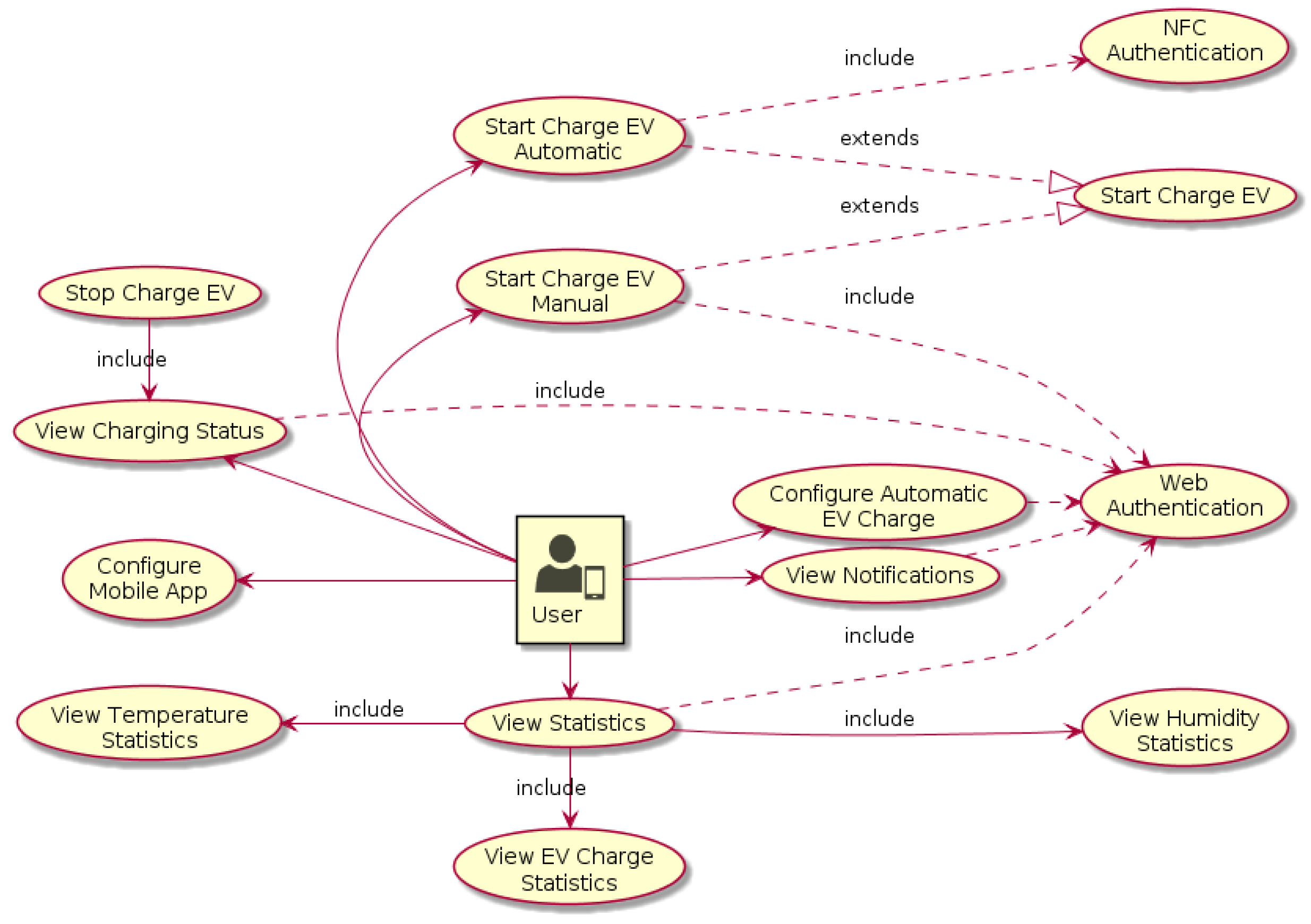
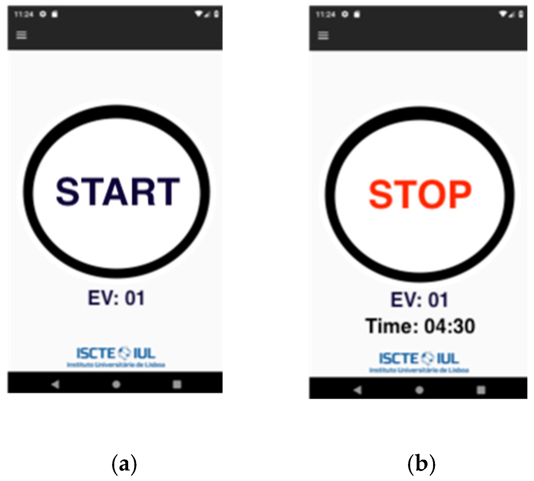
4.2.1. EV Charging Process (Automatic vs. Manual Starting Process)

Initiating the EV charging process is the key function of the mobile app, being simultaneously the most frequent operation, as charging the EV is the purpose of the entire system. Requiring the EV owner to connect to a network where the management unit is reachable, as is illustrated in Figure 3 (assuming that the system operates in a closed network), to be able to start the charging process adds a non-practical, time-consuming process. Aiming to improve the user experience, while performing the operation, we have implemented two approaches: one automatic approach supported by the NFC capabilities of the user’s mobile device and one manual approach relying exclusively on the implemented mobile app. Using a more automatic approach, the user initiates the charging process using the NFC capabilities of his mobile device to authenticate the operation, starting the process by placing his mobile device near to the NFC reader attached to the IoT unit. In this case, the process will use the statistical information collected from the previous operations to confirm the user authentication, estimate the power needs and the amount of time that the EV will be connected to the charging plug (to forecast the power/time usage). Complementary to this process, a more controlled approach can be used, when the NFC device is not available or not attached to the sensor unit, or if the vehicle owner needs to configure the charging process (setting parameters such as the amount of the battery energy according to the state of charge (SoC), the amount of time connected to the platform, time-window for charging, etc.). In this case, the charging process can be initiated by connecting to the network where the management unit is reachable, eventually to the Wi-Fi network provided by the management unit, and manually starting the process, providing the required information. Figure 6 shows the application interfaces to initiate a charging process and to stop the charging process.

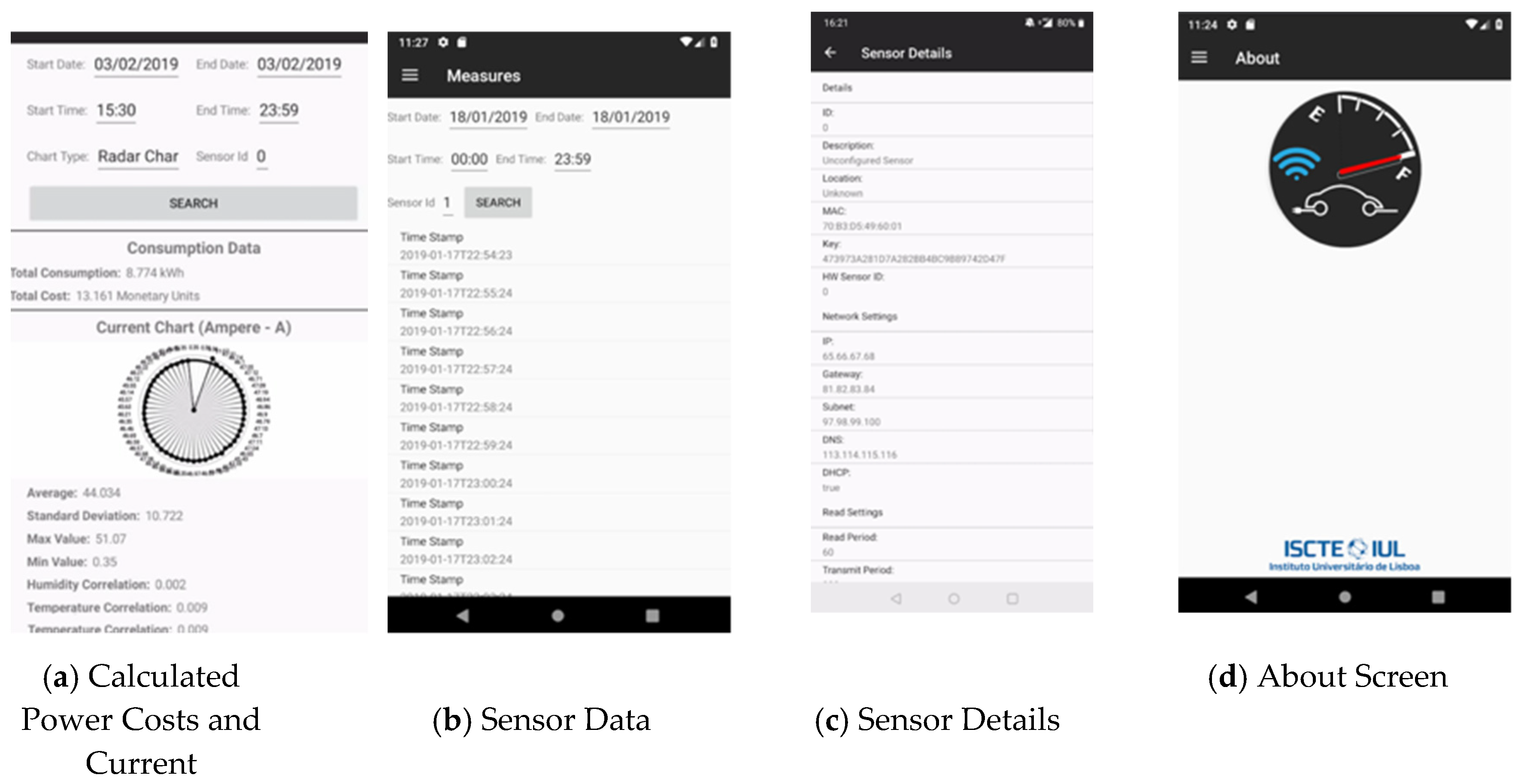
4.2.2. General App Features

Apart from the EV charging process, which can be considered the crux of the system, the mobile app also implements several features that, although not as relevant, are required to achieve a production-grade design stage. Figure 7 and Figure 8 shows screenshots for some of the implemented features:
  • Application splash screen, Figure 7a.
  • Current usage pattern, Figure 7b.
  • Application settings, Figure 7c.
  • Energy costs calculated on the basis of kWh and sensor statistical measures, Figure 8a.
  • List of sensor readings received, Figure 8b.
  • Sensor configuration details, Figure 8c.
  • About screen, Figure 8d.

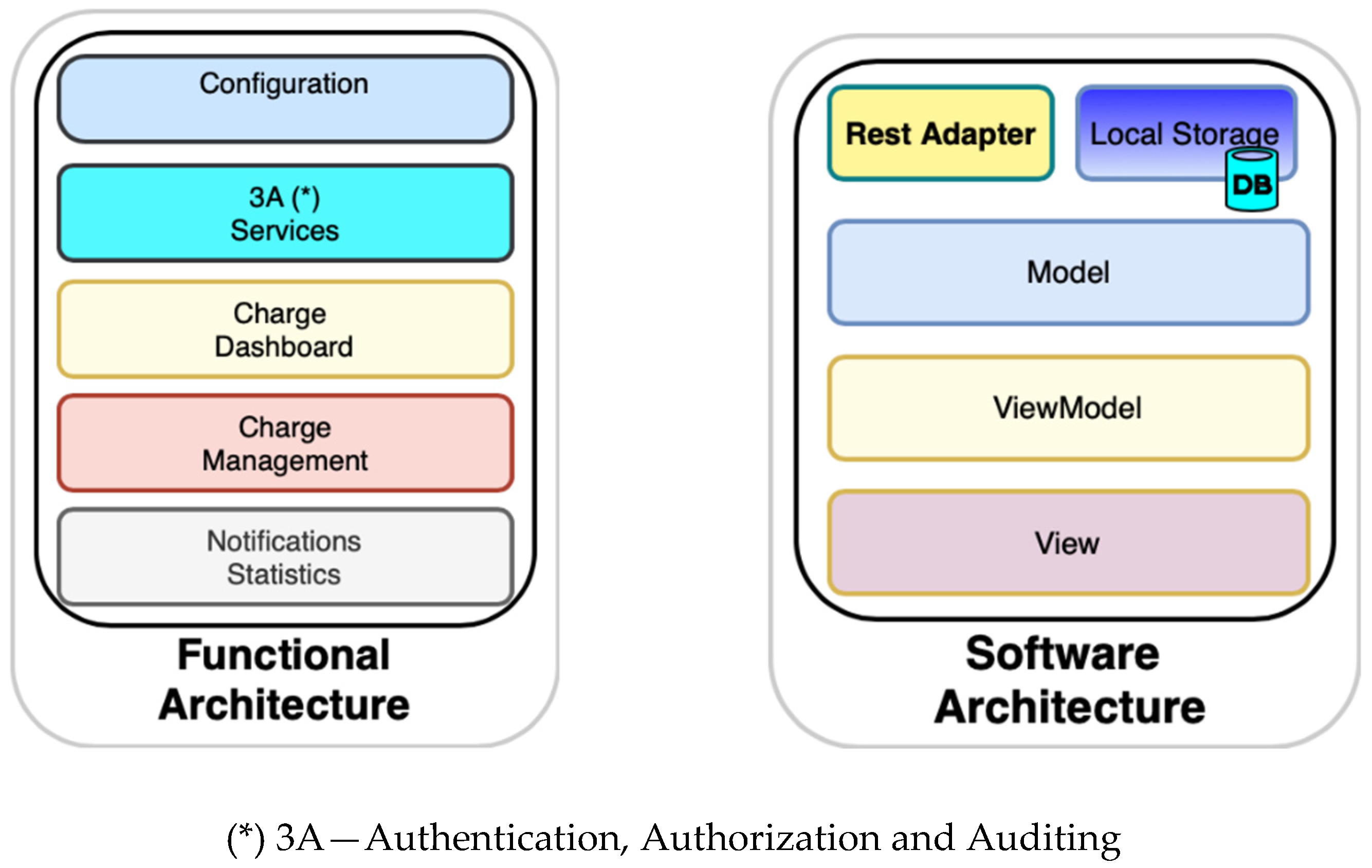
4.2.3. Software Architecture

Figure 9 displays the mobile app software organization. From a functional perspective, the mobile app is split into several modules enforcing the separation of concerns between each functional unit. From the software architecture perspective, the mobile app is implemented following the Model-View-ViewModel (MVVM) pattern, which can be considered one extension of the Presentation Model (PM) pattern [37], frequently used in Xamarin.Forms applications (as well as other mobile apps) where each logical layer has a clear separation of concerns, as described:
  • View, implemented with XAML (eXtensible Application Markup Language), a declarative language used to design and structure the user interface.
  • View-Model is the binding element that intermediates the relationship between the View and the Model, mapping the information and actions between both elements.
  • Model is the representation of the data.
  • Rest Adapter since the mobile app entirely relies on services provided by the management unit, this component acts as a proxy between the mobile application and the services exposed. Due to the financial nature of transactions, the information exchanged between the mobile app and the central management unit uses a secure Hypertext Transfer Protocol Secure [38] (HTTPS) connection (secured by a server certificate) and Hypertext Transfer Protocol [39] (HTTP) standard authentication mechanisms. Stronger authentication schemes can be supported by use of client certificates to authenticate the mobile app requests on the server; however, this was not considered for the current implementation to avoid the complexity of introducing a Public Key Infrastructure (PKI) in the platform.
  • Local Storage consists of a small information repository to store local configuration data in the mobile device.

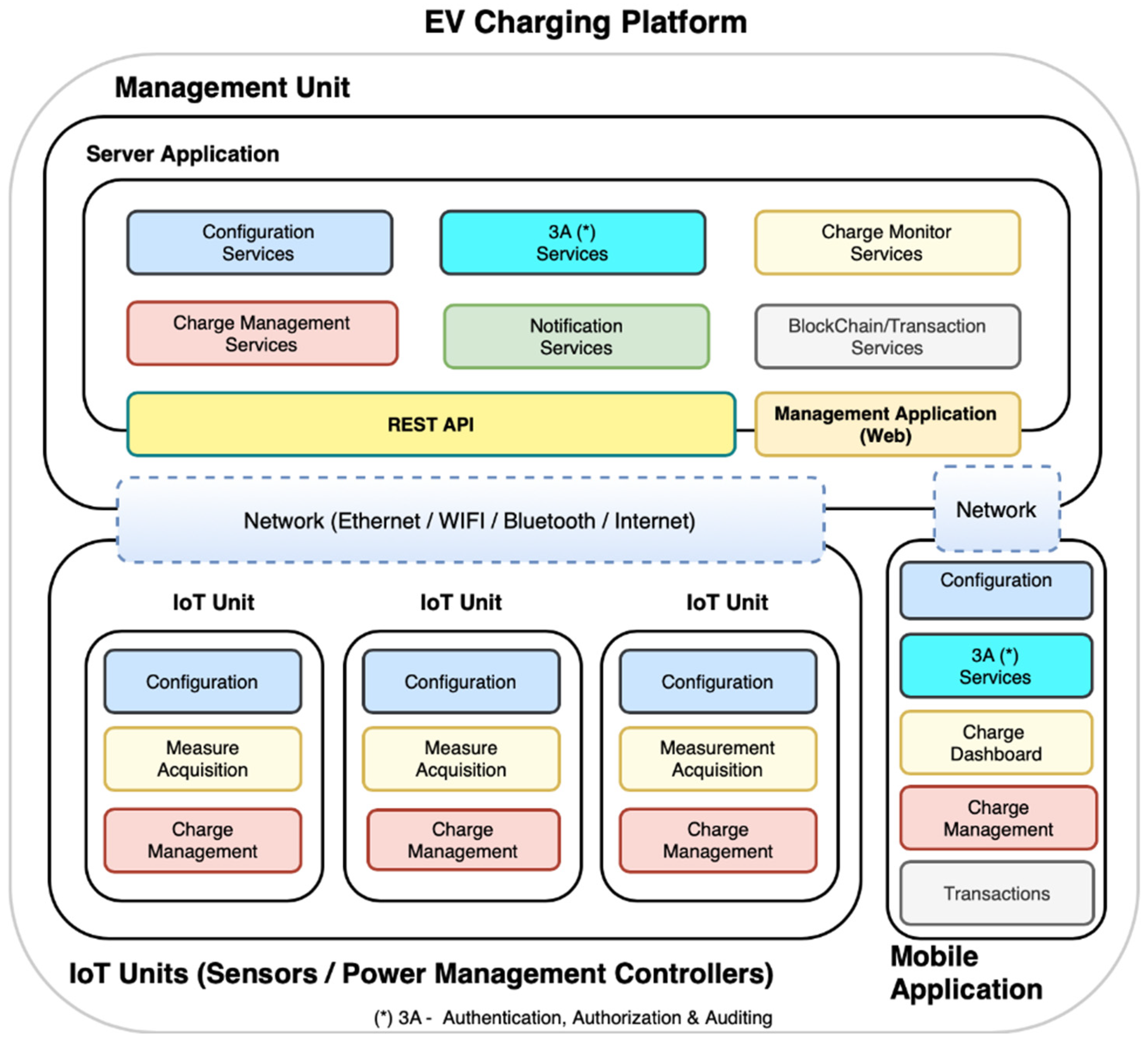
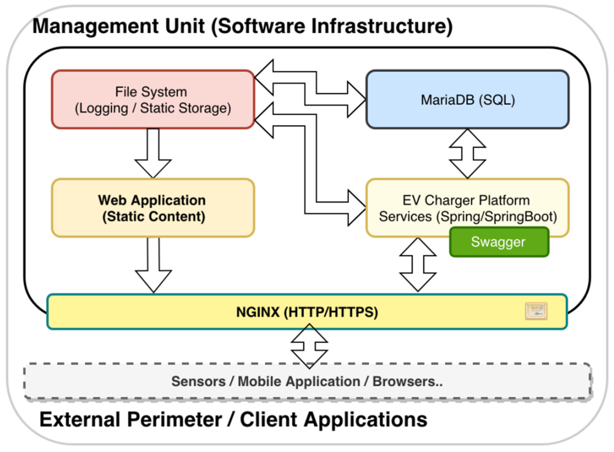
4.3. Management Unit

The management unit is the heart of the platform. This section is divided into the following subsections: Hardware and Network Infrastructure; Software and Services Infrastructure; Management Services; Management Web Application; and the Blockchain.

4.3.1. Hardware and Network Infrastructure

The management unit was built using a Raspberry Pi 3 Model B+ hardware, and the Raspbian operating system. The unit was configured as a Wi-Fi access point, setting up the network to allow Wi-Fi communications between all the platform components (management unit, sensor units and mobile app). This configuration allows the deployment of a completely self-contained, pluggable, low-cost solution, without requiring any other infrastructure components (apart from the energy power grid), while increasing the security of the overall solution by reducing its exposure to external network threats. Complementarily, if deployed in a location with existing network support, the management unit can be connected to the network using the RJ45 Ethernet connector of the Raspberry Pi, allowing the platform to benefit from the existing infrastructure and to eventually be deployed in setups where the use of a Wi-Fi network may not be available or the most suitable option, for instance, a multi-level condominium parking lot, or a parking lot spread over several areas and sharing only one management unit.

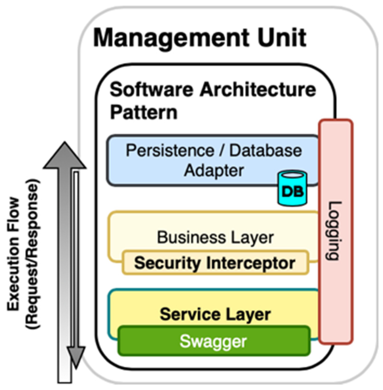
4.3.2. Software and Services Infrastructure

Figure 10 displays the software infrastructure that supports the services exposed to the platform elements (IoT unit, mobile app).
The platform services, built using the Spring Framework and SpringBoot, are exposed as a set of Representational State Transfer (REST) endpoints, self-documented through the use of the Swagger Framework, as presented in Figure 11. This approach exposes an API (Application Programming Interface) that can be easily used by third-party applications, using standard interoperability tools, allowing the development of custom-made integrations (for instance, to integrate the platform with a condominium management system). The platform data is stored in a local MariaDB database server. Aiming to guarantee the security of the communications between the management console, the mobile app and the central unit use a standard HTTPS protocol that has been archived by the installation, and configuration of HTTPS certificates (freely provided by Let’s Encrypt), deployed in an NGINX (Engine X) web server, which acts as a proxy between the “external world” and the services layer.

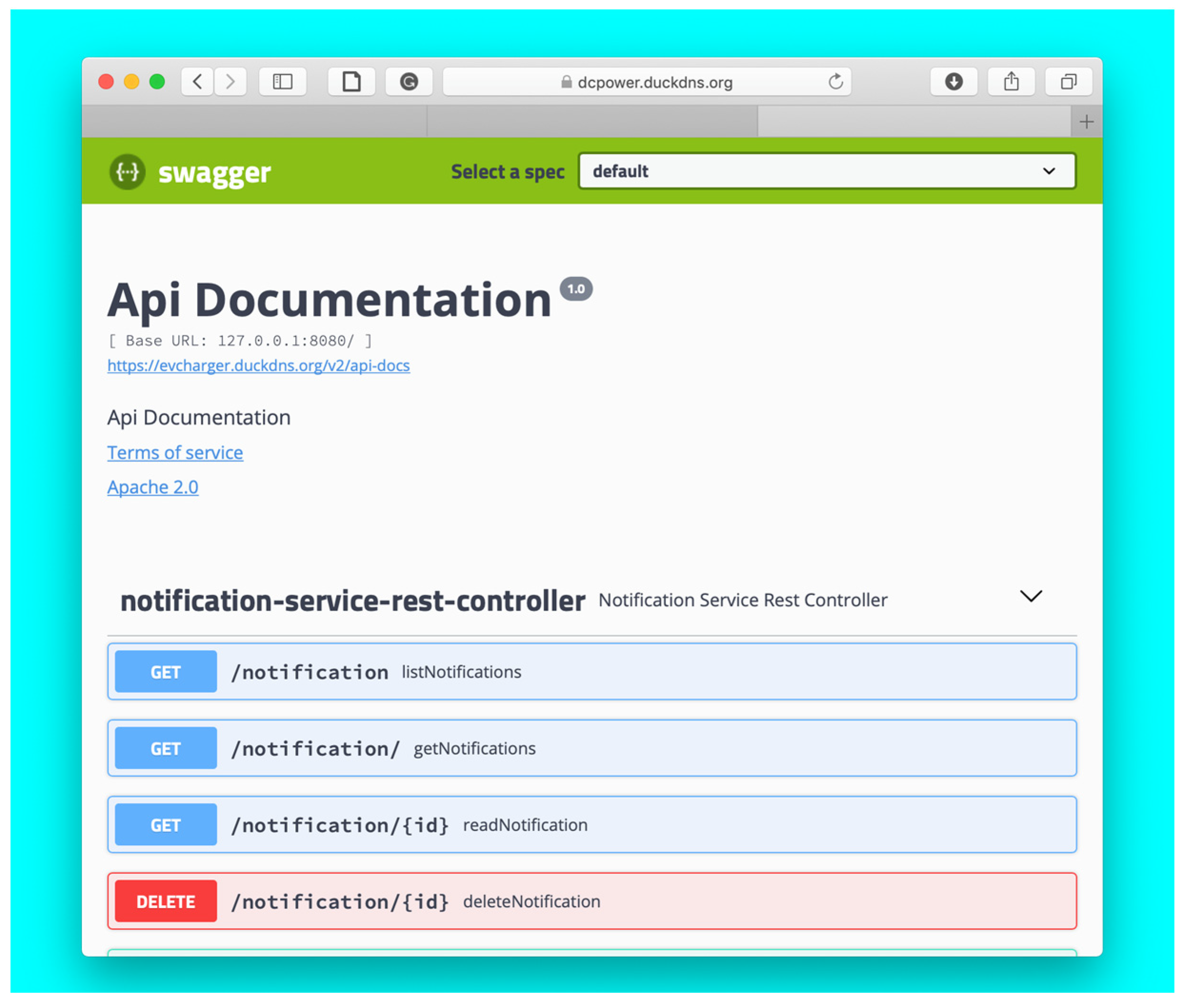
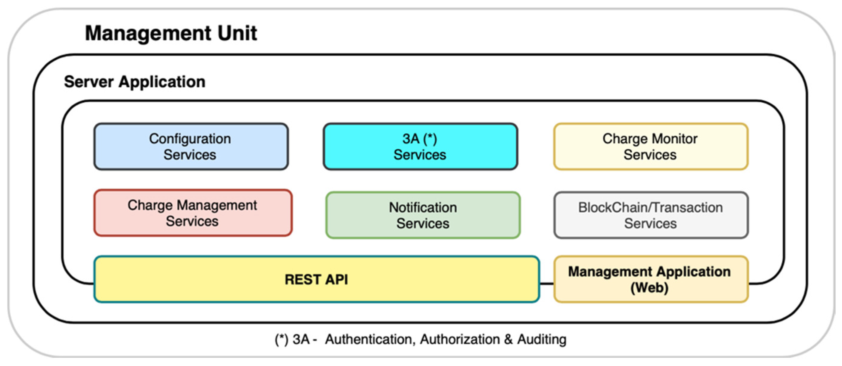
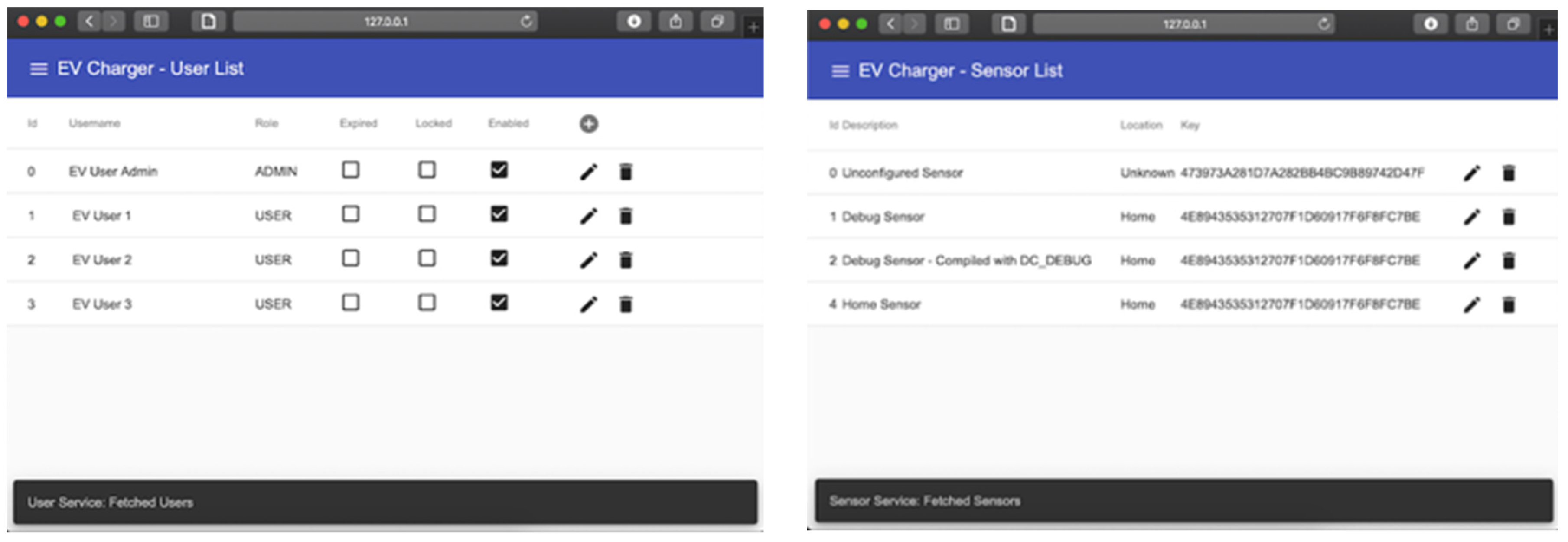
4.3.3. Management Services

Figure 12 presents the application level services that constitute the EV charging platform.
A brief description of the implemented services and their contribution to the overall platform is presented below:
  • Configuration: Provides a set of services required to configure the EV platform, allowing the user to define several platform parameters, such as the existing sensors and their configuration (e.g., network configuration, maximum current, accounting frequency, measure period, etc.), as well as the groups of sensors (sensors inside the same group, maximum load per group, etc.).
  • 3A (Authentication, Authorization, Auditing): This module has a central role in the entire platform. It is responsible for centralizing all the operations related to user/system authentication (“who is who“), authorization (“what can do”) and auditing (“what was done”). Apart from implementing the set of operations to manage the user access to the platform, it also implements the implicit authentication [6] to validate the charging request automatically, based on the current user’s usage pattern.
  • Charge Monitor: This module collects and processes all information generated from the installed sensors to update the EV charging records and detect the end of the charging events, as well as any anomalies on the charging process (e.g., exceeding the nominal current, temperature, charging time), and triggering eventual notifications when required. This module also collects the user’s usage pattern to estimate the power needs for the current charging process, as well as estimate the leave time of the EV from the charging plug, if that information is not provided explicitly by the user.
  • Charge Management: If the installation has the capability to enable or disable the EV charging process, by the use of network-controlled charging devices or by the use of charging switches attached to the sensor unit, the module enables or disables de-charging of the EV, aiming to properly distribute the available charging windows between all the EVs connected to the charging group, based on the charging requirements and the amount of time that the vehicle will be connected to the charging device and using the information provided explicitly by the user or inferred by the platform based on the users usage pattern.
  • Notification Services: This module provides all the notification related services to the platform, routing the system-generated notifications to users that had subscribed to that notification (i.e., vehicle charged, abnormal charge pattern, etc.)
  • Transaction/Blockchain: This module supports all the “financial” related operations, for instance, it records the changing event in the blockchain ledger; if the installation supports the charge management process (described previously), it allows the platform managers to transfer “charging tokens” to the user’s wallet (if not using a public crypto-currency network); it monitors the reception of user’s transferred credit to start the charging process; and it returns the unused credit to the user’s wallet. It also provides minimal reporting capabilities to allow the financial management and analysis of the platform usage.
Each service is implemented following a similar pattern to the pattern presented in Figure 13, where the responsibilities of each are defined as follows:
  • Service Layer: Acts as a mapping service, translating the external representation of the information to the internal representation.
  • Business Layer: All the application behaviour level is defined on this layer, and any interaction between layers made exclusively through the interface provided at this level.
  • Persistence Layer: This layer maps the internal representation of the information to representation used by the database engine.

4.3.4. Web Application

The management unit exposes a web application, developed in Angular, which relies on the services exposed and allows the EV platform managers to monitor, configure and operate the platform. It also provides to the platform users a complementary user interface that, although supporting only a reduced set of the operations available on the native mobile app, allows the users to interact with the platform using browser-only technologies, available in a wider range of devices. Figure 14 displays some screenshots for the management unit web application.

4.3.5. Blockchain Implementation and Integration

The transactions between the users and the platform rely on the exchange of EV charging tokens (self-generated). If using a “public” crypto-currency infrastructure like Ethereum (or Bitcoin), the trades are made using that crypto-currencies (which can be exchanged in the market). Currently, the transaction is performed with a fixed energy price or based on pre-defined rules but, in the future, the price can be negotiated dynamically in full implementation of a smart grid [19]. This implementation uses the same approach of our previous work on this topic [19]. Figure 15 presents the interactions with a blockchain network using a private/internal blockchain ledger, whereas Figure 16 shows the interactions that would be held when using an “open” cryptocurrency (e.g., Bitcoins).
The sequence of operations presented in Figure 15 and Figure 16 are explained as follows.
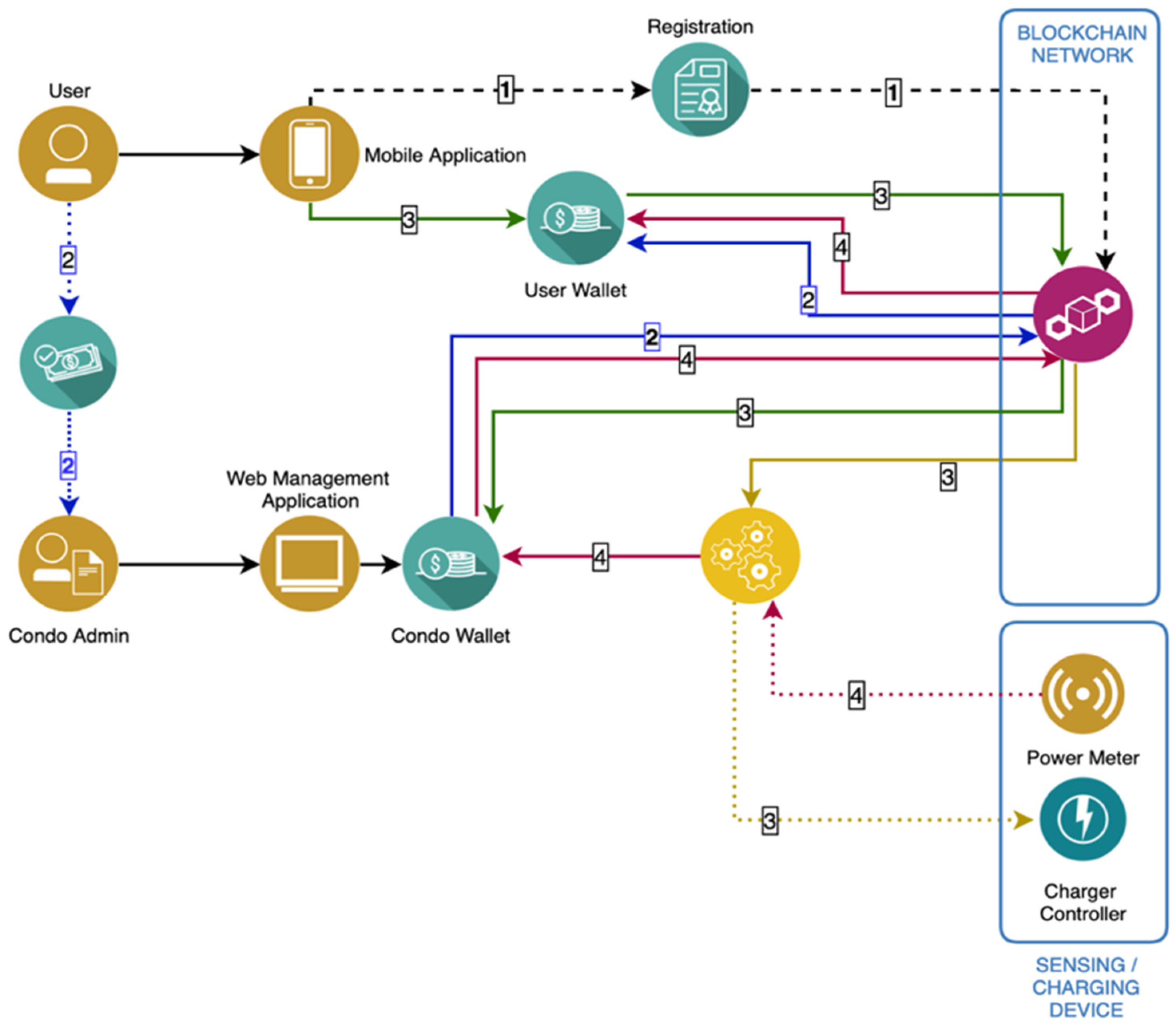
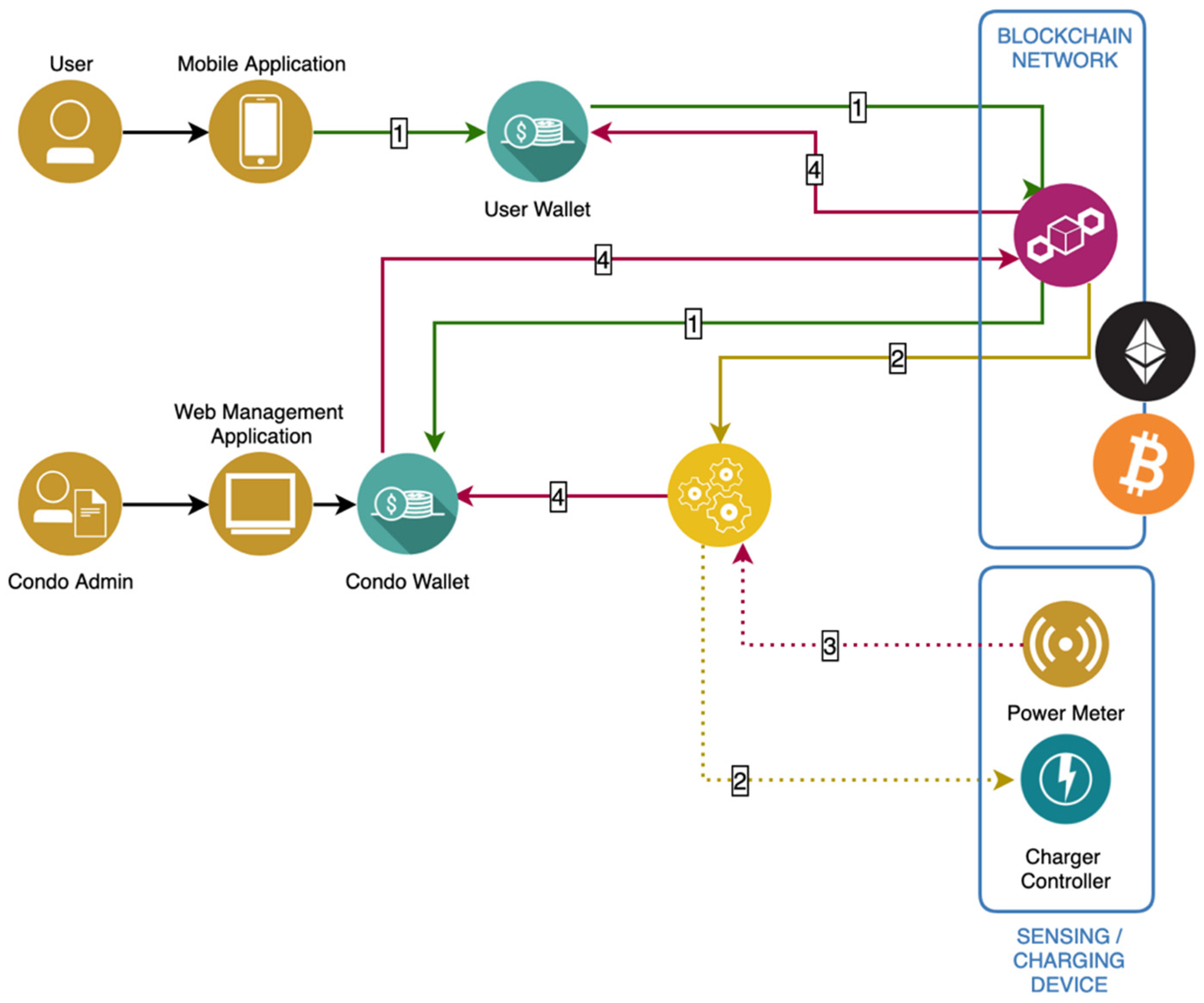
  • Using the mobile app, the user registers/creates his account on the blockchain network (if using public crypto-currency infrastructure, the user creates his crypto-currency wallet).
  • Using real money, the user buys EV charging tokens from the EV platform management, referring to the web interface of the Management Unit. The charging tokens are transferred from the platform wallet to the user wallet through a blockchain network (if using a public crypto-currency the user buys the currency on the market).
  • Using the mobile app, the user sends charging tokens from his wallet to the EV platform wallet, defining the maximum amount to spend and the maximum time that the vehicle will be connected to the plug (used to optimize the power distribution). The Management Unit receives the transfer from the network and triggers the power management unit to start the charging process, which may not be immediate due to the optimization of the power distribution between the used chargers.
  • The Management Server receives the power measures from the charger, stopping the charging process when the maximum amount is reached, the maximum charging time is reached, or when the vehicle is removed from the charger (detected by a reduction of the consumed power). If the charging process is interrupted, the remaining amount is returned by the Management Server to the user wallet using the blockchain network.

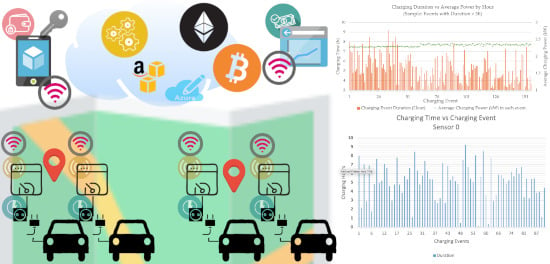
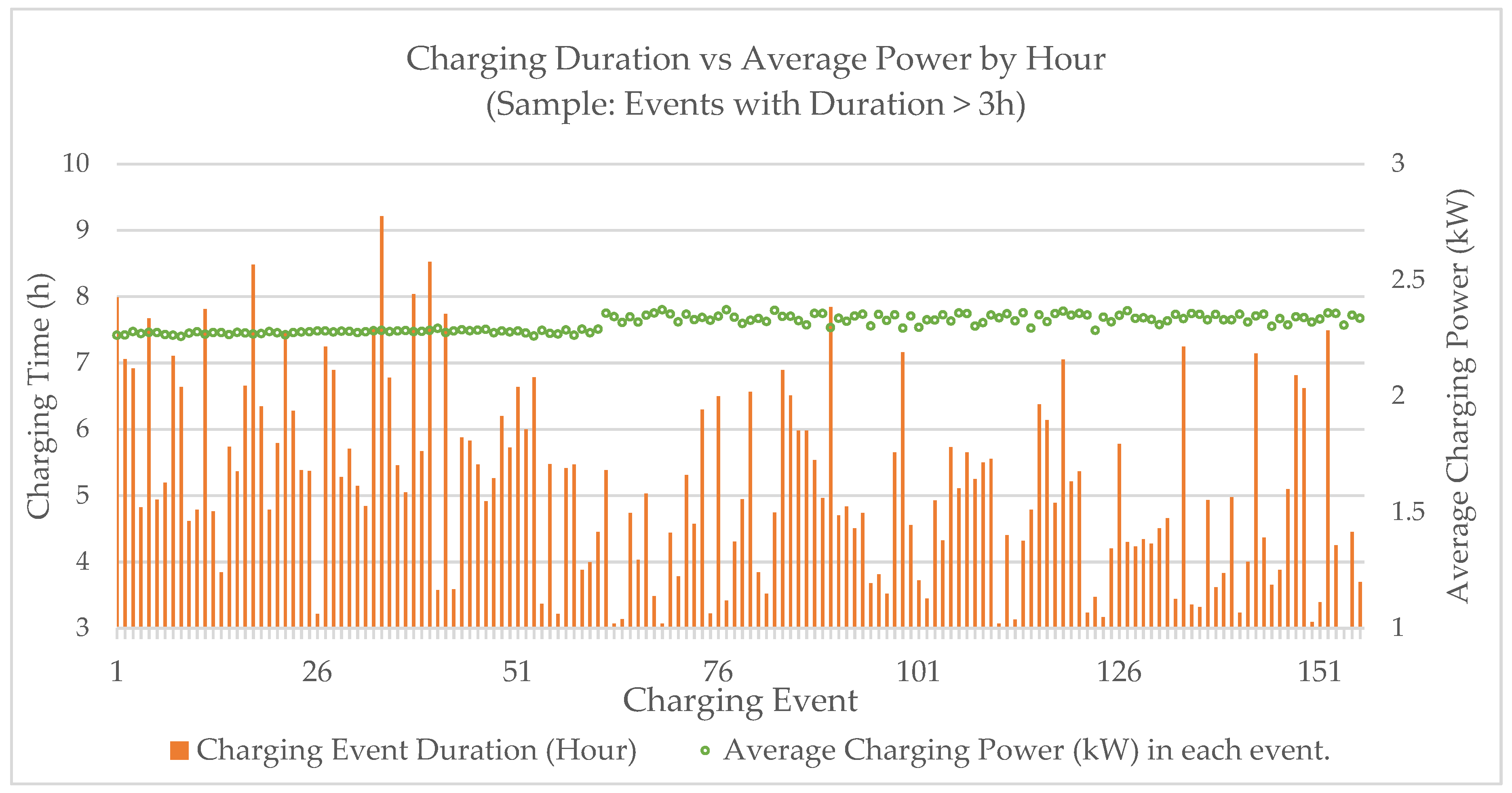
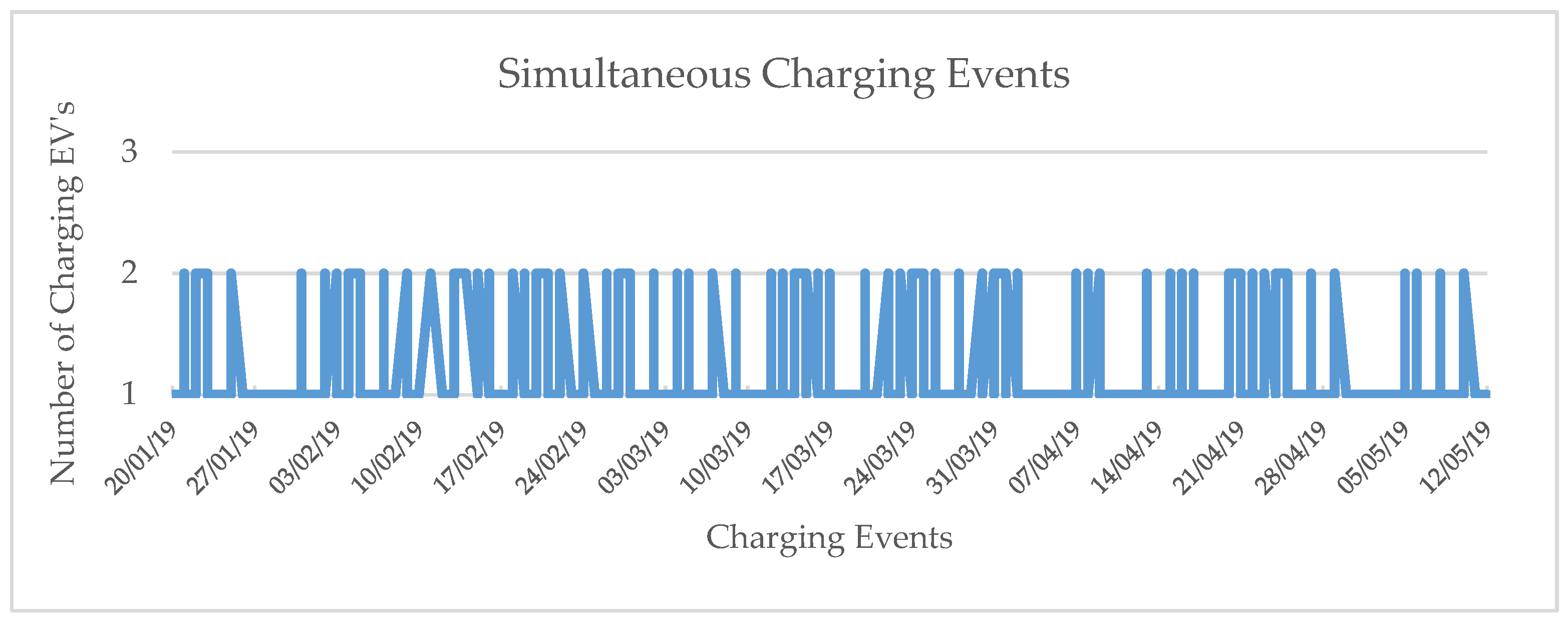
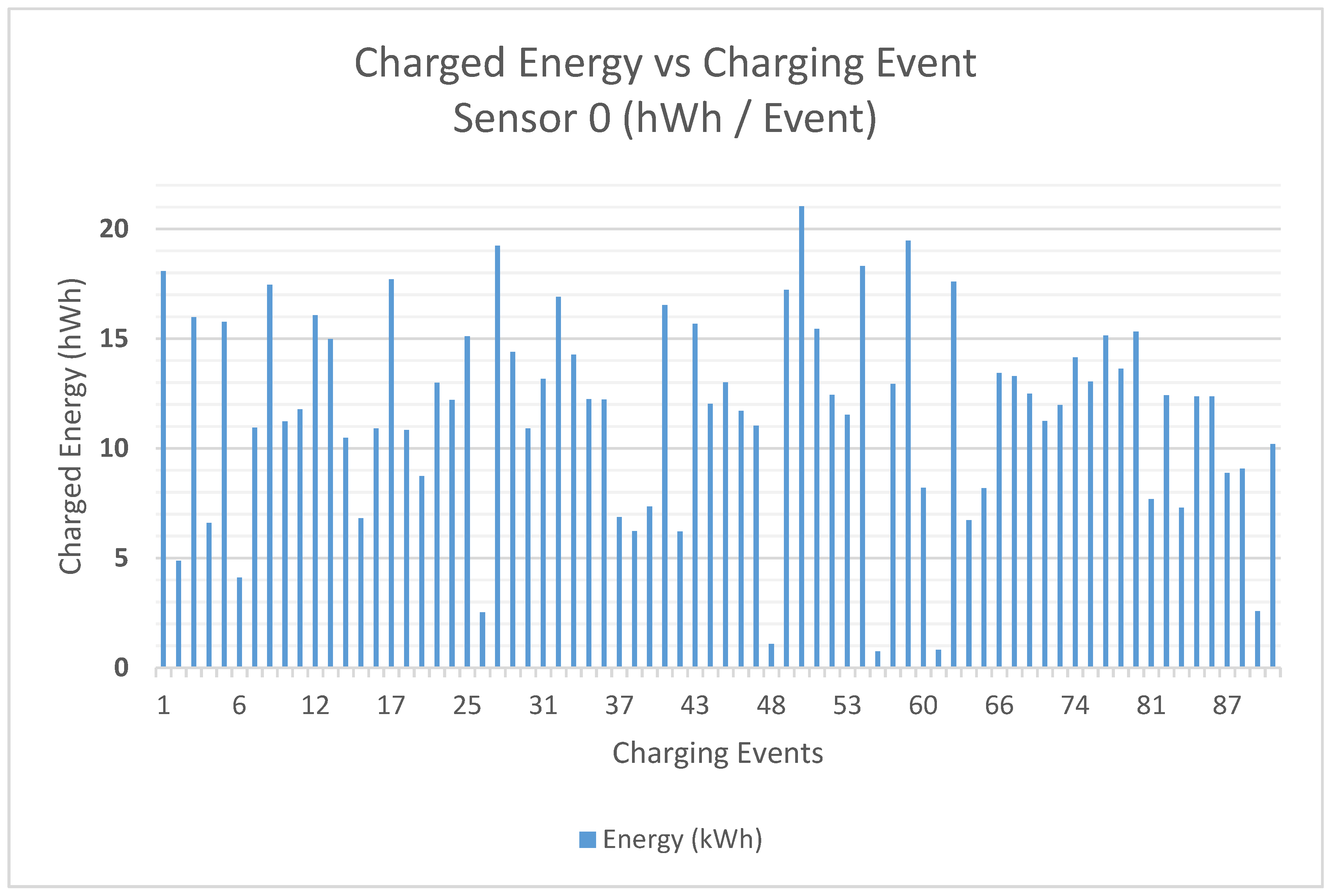
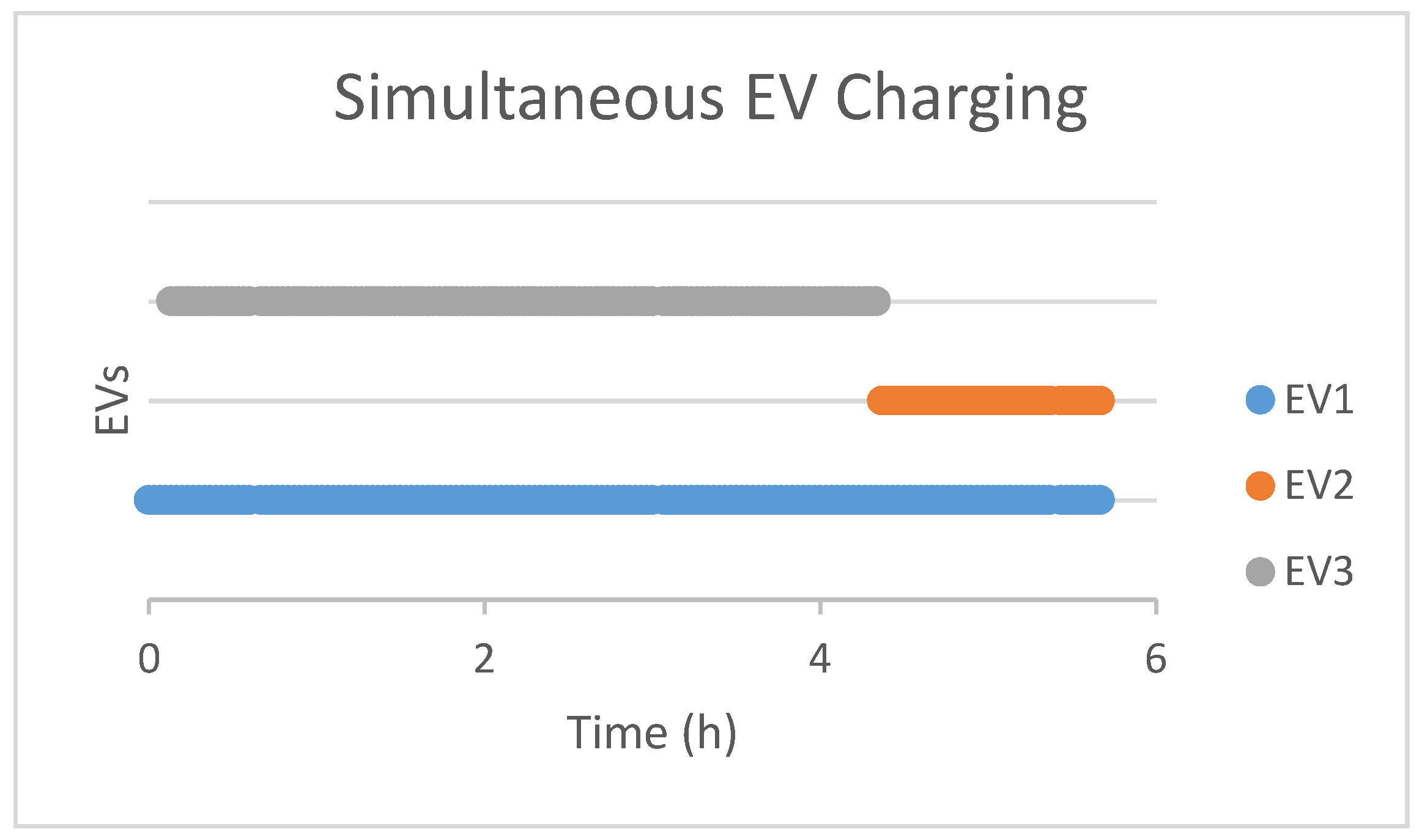
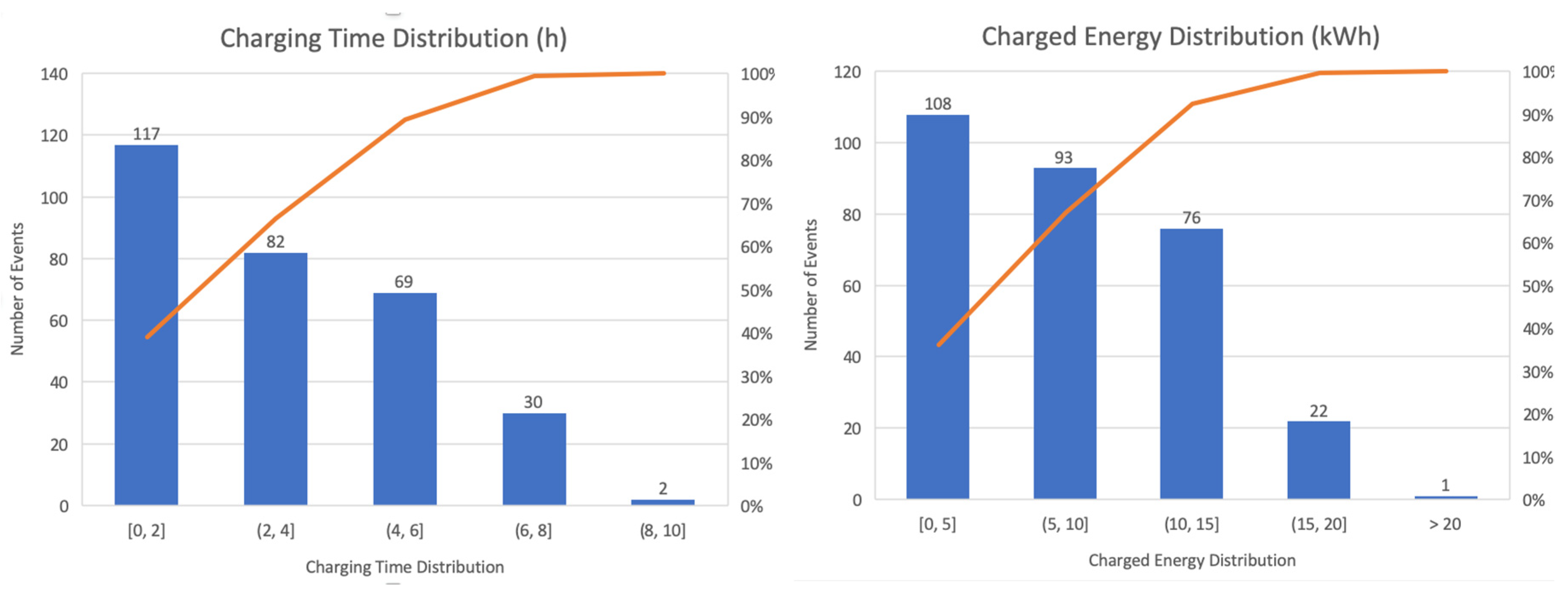
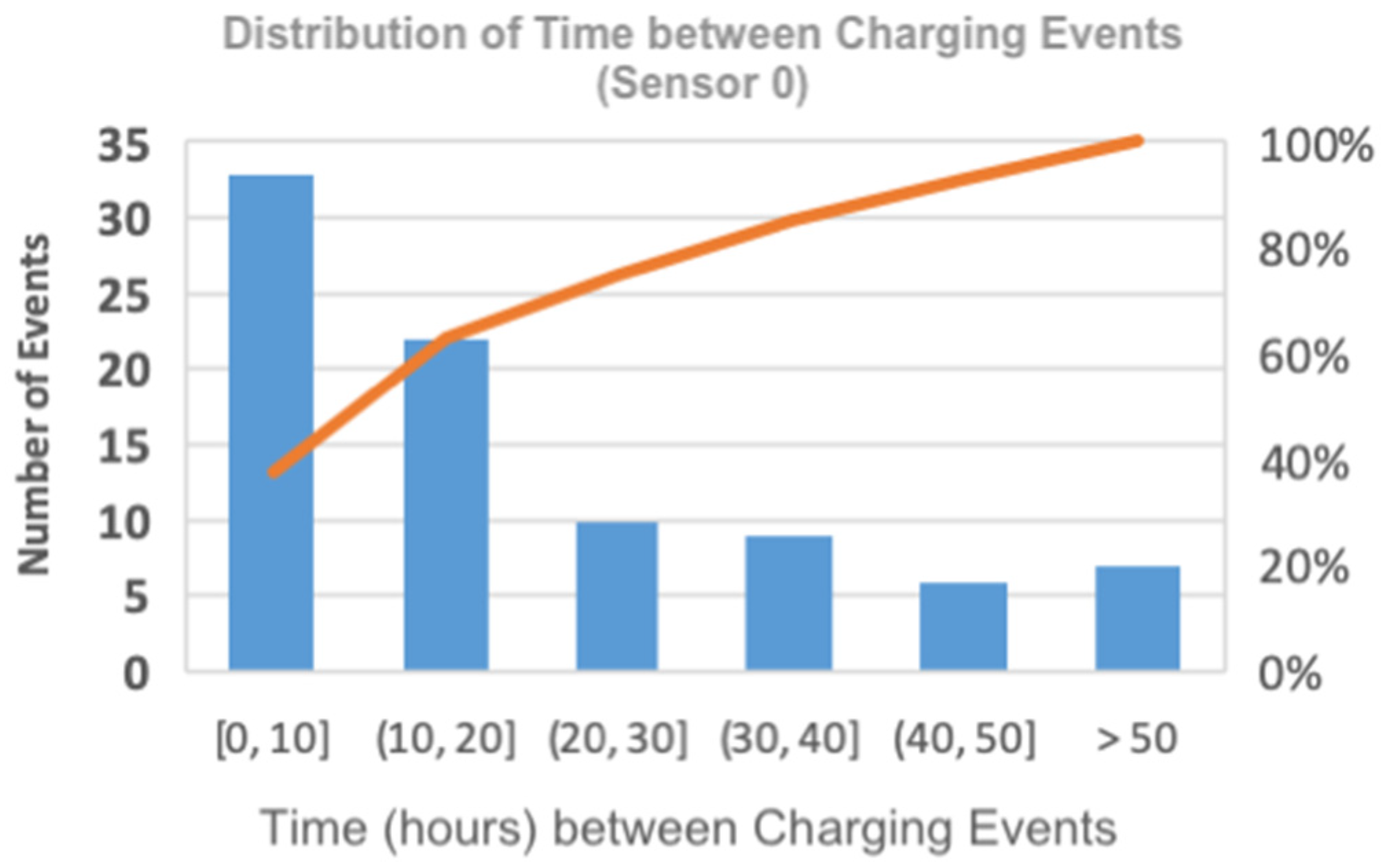
5. Case Study at a Condominium

We applied the current approach to a shared place in a condominium, where three EV owners shared the condominium electric installation available at parking places for a period of 3.5 months. Each sensor was configured to generate one sample each minute, allowing further study of the current load patterns during a charging event. A set of three EVs (all Leaf vehicles with 24 kWh battery capacity) and three independent sensors (Sensor 0; Sensor 1; Sensor 2) were used; Figure 17 presents the diagram of the test environment for the case study. Due to physical constraints of the installation, the charging adapter connected to Sensor 0 was directly connected to the power grid, without one intermediate switch (“always on” on the scheme).
Figure 18 presents photos of one of the developed prototypes. Figure 18a shows a photo of one of the IoT unit prototypes installed (Label (3) in Figure 18a) of the test environment, measuring the current with the non-intrusive SCT-013-000-100A sensor (Label (1) in Figure 18a). In this case, due to the weak Wi-Fi signal at the install location and the absence of other network infrastructure, the sensor unit was connected, using the RJ45 Ethernet interface, to a Wi-Fi Range Extender (Label (2) in Figure 18a) to amplify the signal, allowing the IoT unit to reach the Management Unit accessible from the network where the Wi-Fi Range Extender was connected. Figure 18b shows the contents of the IoT unit installed in Figure 18a (Label (3)).
Table 2 summarizes the data collected during the case study.
Figure 19 shows the charging time and the average charging power for each charging event (for events with > 3 h of charging duration), where it is possible to identify an average value of 2.3 kW, approximately (assuming an root mean square, RMS, voltage value of 230 V). The absence of a strong correlation between the charging time and the average charging power is also observable (the correlation coefficient between the charging duration and the charging power dataset is −0.30), which suggests that the average charged power by hour load is limited by the charging device and not directly dependent of the amount of energy required to charge the EV (e.g., a charging event of 6 h has a similar average charging power as a charging event with 3 h).
Figure 20 displays simultaneous charging events for the entire period analysed (330 charging events on 20 January and 12 May). Due to the power limitations, only two EVs are allowed to be charging at the same time, using full charging power, and the power is delivered on a first-come, first-served (FCFS) basis, where the platform controls the maximum number of stations that are allowed to charge the EVs simultaneously, queueing the remaining charging requests until a charging slot is available.
Since the charging platform measures the supplied power continuously, it detects when the EV is fully charged. At that time, it interrupts the EV charging process, transfers the data to the blockchain network (to account for the transaction performed), and starts supplying energy to the next EV queued. Supported by the drivers’ consumption profile and the statistical information about their behavior (taken from past stored data, average power required, the average number of hours before the vehicle is unplugged, etc.) a priority/utility-based resource scheduler can be applied to maximize the benefits/utility of the energy supplied.
Figure 21 shows the charging sessions of a Leaf with 24 kWh battery capacity, in a 3.5 month period, where it is possible to verify charging session periods ranging from 1 to 9 h (with an arithmetic average of 5.12 h and standard deviation of 2.03 h), and Figure 22 shows the charged energy, which varies between 2 kWh and 22 kWh (with an arithmetic average of 11.67 kWh and standard deviation of 4.58 kWh). It is possible to identify in this figure that, on average, this driver only charges 52% of the total charge and uses, on average, 5.5 h to charge the EV. From this approach, it is possible to identify driver profiles and use this for future charging processes accounting for the power limitation, as is shown in [19,22].
Figure 23 shows the charging process with three EVs at the condominium, where it is possible to identify that, due to the power limitation, EV2 had to wait for an available charging window.
Figure 24 presents the distributions for the charging time (left) and for the charged energy (right) for each charging event. It can be observed that for 89% of the charging events ((117 + 82 + 69)/300), the EV will be charging for 6 h or less. A similar analysis can be made for the charging energy, where for 92% ((108 + 93 + 76)/300) of the charging events, the EV will charge 15 kWh, which represents roughly 62.5% of the total battery capacity.
Several usages pattern also were observed. Figure 25 displays the distribution of the amount of time between each EV charging event, which shows that for 64% of the times the driver charges the EV with less than 20 h between charging events, which may be correlated with the commute journey.

6. Future Implication of Mobile Devices as a Payment System for EV Charging

EVs face several problems when going abroad, due to the need for previous planning in getting charging cards from foreign operators in a process that is not easy. The developed app for the condominiums can be adapted for public charging with an identity management process and a secure environment provided by the blockchain.
This approach can be similarly applied for mobile ticketing systems, allowing users to buy public transportation tickets using mobile devices (see [27] as an example of this work), or pay motorway fees and for other services.
Some commercial approaches are currently being tested; for example, charging stations in the UK will be equipped with NFC payment technology [40]. In future work, we will perform security tests on this approach and develop an interface to a payment service.

7. Conclusions

The work presented in this paper explores different approaches based on IoT, mobile devices and blockchain to create a novel solution for the EV charging process in shared spaces with authentication and security features, accounts and a transaction system. This approach can contribute to the proliferation of EVs, because one of their current barriers is the charging process at condominiums and rented houses. Moreover, from this solution, it is possible to identify EV charging profiles, create patterns to handle power limitations and share services without the need for new individual services. This approach can also be applied to handle energy transactions in other application scenarios, such as micro-generation without a central supervision control mechanism, although the use of open public cryptocurrency platforms like Bitcoin or Ethereum, due to high transaction costs, can create some barriers to the acceptance of the model.
The proposed solution demonstrated the robustness of the developed prototype for an EV charging process in shared spaces in the context of the presented case study at a condominium. During the 3.5 month of operation, there was only one failure of an IoT sensor unit due to a general power failure, and the problem was corrected by simply delaying the start of the charging process. Although no network-related limitations were identified while using traditional wired (Ethernet) and wireless (Wi-Fi) local area network (LAN) technologies to establish communication between the IoT devices and the Management Unit for the presented case study environment, the implementation of the system in wider geographical environments or other building topologies may require the use of wireless communication technologies more suitable for that context, for instance, low-power wide-area network (LPWAN) technologies such as LoRa, Sigfox, NB-IoT or LTE-M.

Author Contributions

J.P.M. is a Master student that performed all development work. J.C.F. is a thesis supervisor and organized all work in the computer science subject, and the other authors revised the document and collaborated on energy and power electronics, as well as in IoT topics.

Funding

This work has been partially supported by Portuguese National funds through FITEC programa Interface, with reference CIT “INOV—INESC Inovação—Financiamento Base”.

Conflicts of Interest

The authors declare no conflict of interest.

References

  1. Al-Fuqaha, A.; Guizani, M.; Mohammadi, M.; Aledhari, M.; Ayyash, M. Internet of things: A survey on enabling technologies, protocols, and applications. IEEE Commun. Surv. Tutor. 2015, 17, 2347–2376. [Google Scholar] [CrossRef]
  2. Stat of the Week: Percent of Households That Rent By Country. Available online: https://evadoption.com/stat-of-the-week-percent-of-households-that-rent-by-country/ (accessed on 21 May 2019).
  3. Axsen, J.; Goldberg, S.; Bailey, J.; Kamiya, G.; Langman, B.; Cairns, J.; Wolinetz, M.; Miele, A. Electrifying Vehicles: Insights from the Canadian Plug-in Electric Vehicle Study; Simon Fraser University: Vancouver, BC, Canada, 2015. [Google Scholar]
  4. Lopez-Behar, D.; Tran, M.; Mayaud, J.R.; Froese, T.; Herera, O.; Merida, W. Putting electric vehicles on the map: A policy agenda for residential charging infrastructure in Canada. Energy Res. Soc. Sci. 2019, 50, 29–37. [Google Scholar] [CrossRef]
  5. Ismail, B.I.; Goortani, E.M.; Ab Karim, M.B.; Tat, W.M.; Setapa, S.; Luke, J.Y. Evaluation of docker as edge computing platform. In Proceedings of the 2015 IEEE Conference on Open Systems (ICOS 2015), Melaka, Malasya, 24–26 August 2015. [Google Scholar]
  6. Ferreira, J.C.; Monteiro, V.; Afonsom, J.L. Vehicle-to-Anything Application (V2Anything App) for electric vehicles. IEEE Trans. Ind. Inform. 2014, 10, 1927–1937. [Google Scholar] [CrossRef]
  7. Bo, C.; Zhang, L.; Li, X.-Y.; Huang, Q.; Wang, Y. Silentsense: Silent user identification via touch and movement behavioral biometrics. In Proceedings of the 19th Annual International Conference on Mobile Computing & Networking (MobiCom ’13), Miami, FL, USA, 30 September–4 October 2013; ACM: New York, NY, USA, 2013; pp. 187–190. [Google Scholar] [CrossRef]
  8. Patel, V.M.; Chellappa, R.; Chandra, D.; Barbello, B. Continuous User Authentication on Mobile Devices: Recent progress and remaining challenges. IEEE Signal Process. Mag. 2016, 33, 49–61. [Google Scholar] [CrossRef]
  9. De Luca, A.; Hang, A.; Brudy, F.; Lindner, C.; Hussmann, H. Touch me once and iknow it’s you!: Implicit authentication based on touch screenpatterns. In Proceedings of the SIGCHI Conference on Human Factors in Computing Systems (CHI ’12), Austin, TX, USA, 5–10 May 2012; ACM: New York, NY, USA, 2012; pp. 987–996, ISBN 978-1-4503-1015-4. [Google Scholar] [CrossRef]
  10. Feng, T.; Liu, Z.; Kwon, K.-A.; Shi, W.; Carbunar, B.; Jiang, Y.; Nguyen, N. Continuous mobile authentication using touchscreen gestures. In Proceedings of the 2012 IEEE Conference on Technologies for Homeland Security (HST 2012), Waltham, MA, USA, 13–15 November 2012; pp. 451–456, ISBN 978-1-46732709-1. [Google Scholar] [CrossRef]
  11. Jakobsson, M.; Shi, E.; Golle, P.; Chow, R. Implicit authentication for mobile devices. In Proceedings of the 4th USENIX Conference on Hot Topics in Security (HotSec’09), Montreal, QC, Canada, 10–14 August 2009; USENIX Association: Berkeley, CA, USA, 2009; p. 9. [Google Scholar]
  12. Sae-Bae, N.; Ahmed, K.; Isbister, K.; Memon, N. Biometric-rich gestures: A novel approach to authentication on multi-touch devices. In Proceedings of the SIGCHI Conference on Human Factors in Computing Systems (CHI ’12), Austin, TX, USA, 5–10 May 2012; ACM: New York, NY, USA, 2012; pp. 977–986, ISBN 978-1-4503-1015-4. [Google Scholar] [CrossRef]
  13. Frank, M.; Biedert, E.M.R.; Martinovic, D.S.I. Touchalytics: On the applicability of touchscreen input as a behavioral biometric for continuous authentication. IEEE Trans. Inf. Forensics Secur. 2013, 8, 136–148. [Google Scholar] [CrossRef]
  14. Nakamoto, S. Bitcoin: A Peer-to-Peer Electronic Cash System. Available online: https://bitcoin.org/bitcoin.pdf (accessed on 8 July 2019).
  15. A Next-Generation Smart Contract and Decentralized Application Platform. Available online: https://github.com/ethereum/wiki/wiki/White-Paper (accessed on 8 July 2019).
  16. Panarello, A.; Tapas, N.; Merlino, G.; Longo, F.; Puliafito, A. Blockchain and IoT integration: A systematic survey. Sensors 2018, 18, 2575. [Google Scholar] [CrossRef] [PubMed]
  17. Pop, C.; Antal, M.; Cioara, T.; Anghel, I.; Sera, D.; Salomie, I.; Raveduto, G.; Ziu, D.; Croce, V.; Bertoncini, M. Blockchain-based scalable and tamper-evident solution for registering energy data. Sensors 2019, 19, 3033. [Google Scholar] [CrossRef] [PubMed]
  18. Erdin, E.; Cebe, M.; Akkaya, K.; Solak, S.; Bulut, E.; Uluagac, S. Building a Private Bitcoin-based Payment Network among Electric Vehicles and Charging Stations. In Proceedings of the 2018 International Conference in Blockchain, Xi’an, China, 10–12 December 2018. [Google Scholar]
  19. Ferreira, J.C.; Martins, A.L. Building a community of users for open market energy. Energies 2018, 11, 2330. [Google Scholar] [CrossRef]
  20. Sanseverino, E.R.; Silvestre, M.L.D.; Gallo, P.; Zizzo, G.; Ippolito, M. The blockchain in microgrids for transacting energy and attributing losses. In Proceedings of the 2017 IEEE International Conference on Internet of Things (iThings) and IEEE Green Computing and Communications (GreenCom) and IEEE Cyber, Physical and Social Computing (CPSCom) and IEEE Smart Data (SmartData), Exeter, UK, 21–23 June 2017; pp. 925–930. [Google Scholar]
  21. Ferreira, J.C.; Monteiro, V.; Afonso, J.L. Smart electric vehicle charging system. In Proceedings of the 2011 IEEE Intelligent Vehicles Symposium (IV 2011), Baden, Germany, 5–9 June 2011. [Google Scholar]
  22. Ferreira, J.C.; Afonso, J.L. EV-cockpit—Mobile personal travel assistance for Electric vehicles. In Advanced Microsystems for Automotive Applications 2011; Springer: Berlin/Heidelberg, Germany, 2011. [Google Scholar]
  23. Ferreira, J.C.; Monteiro, V.; Afonso, J.; Afonso, J.L. An energy management platform for public buildings. Electronics 2018, 7, 294. [Google Scholar] [CrossRef]
  24. Pustišek, M.; Kos, A.; Sedlar, U. Blockchain based autonomous selection of electric vehicle charging station. In Proceedings of the 2016 International Conference on Identification, Information and Knowledge in the Internet of Things (IIKI), Beijing, China, 20–21 October 2016; pp. 217–222. [Google Scholar] [CrossRef]
  25. Liu, C.; Chai, K.K.; Zhang, X.; Lau, E.T.; Chen, Y. Adaptive blockchain-based electric vehicle participation scheme in smart grid platform. IEEE Access 2018, 6, 25657–25665. [Google Scholar] [CrossRef]
  26. Thakur, S.; Breslin, J.G. Electric vehicle charging queue management with blockchain. In Internet of Vehicles. Technologies and Services Towards Smart City. IOV 2018. Lecture Notes in Computer Science; Skulimowski, A., Sheng, Z., Khemiri-Kallel, S., Cérin, C., Hsu, C., Eds.; Springer: Cham, Switzerland, 2018; Volume 11253, pp. 249–264. [Google Scholar]
  27. Ferreira, J.C. Android as a Cloud Ticket Validator. In Proceedings of the International Conference on Cloud Ubiquitous Computing Emerging Technologies (CUBE 2013), Pune, India, 15–16 November 2013. [Google Scholar] [CrossRef]
  28. Dahlberg, T.; Guo, J.; Ondrus, J. A critical review of mobile payment research. Electron. Commer. Res. Appl. 2015, 14, 265–284. [Google Scholar] [CrossRef]
  29. Higgins, S. Why a German Power Company is Using Ethereum to Test Blockchain Car Charging. CoinDesk. 7 March 2016. Available online: http://www.coindesk.com/german-utility-company-turns-to-blockchain-amid-shifting-energy-landscape/ (accessed on 8 July 2019).
  30. Allison, I. RWE and Slock.it—Electric Cars Using Ethereum Wallets Can Recharge by Induction at Traffic Lights. International Business Times UK. 22 Feburary 2016. Available online: http://www.ibtimes.co.uk/rwe-slock-it-electric-cars-using-ethereum-wallets-can-recharge-by-inductiontraffic-lights-1545220 (accessed on 8 July 2019).
  31. Kang, J.; Yu, R.; Huang, X.; Maharjan, S.; Zhang, Y.; Hossain, E. Enabling localized peer-to-peer electricity trading among plug-in hybrid electric vehicles using consortium blockchains. IEEE Trans. Ind. Inf. 2017, 13, 3154–3164. [Google Scholar] [CrossRef]
  32. Garg, S.; Kaur, K.; Kaddoum, G.; Gagnon, F.; Rodrigues, J.J. An efficient blockchain-based hierarchical authentication mechanism for energy trading in V2G environment. arXiv 2019, arXiv:1904.01171. [Google Scholar]
  33. Liu, D.; Li, D.; Liu, X.; Ma, L.; Yu, H.; Zhang, H. Research on a cross-domain authentication scheme based on consortium blockchain in V2G networks of smart grid. In Proceedings of the 2nd IEEE Conference on Energy Internet and Energy System Integration (EI2), Beijing, China, 20–22 October 2018. [Google Scholar]
  34. Aitzhan, N.Z.; Svetinovic, D. Security and privacy in decentralized energy trading through multi-signatures, blockchain and anonymous messaging streams. IEEE Trans. Dependable Secur. Comput. 2018, 15, 840–852. [Google Scholar] [CrossRef]
  35. Mengelkamp, E.; Notheisen, B.; Beer, C.; Dauer, D.; Weinhardt, C. A blockchain-based smart grid: Towards sustainable local energy markets. Comput. Sci. Res. Develop. 2018, 33, 207–214. [Google Scholar] [CrossRef]
  36. Münsing, E.; Mather, J.; Moura, S. Blockchains for decentralized optimization of energy resources in microgrid networks. In Proceedings of the IEEE Conference on Control Technology and Applications (CCTA 2017), Kohala Coast, HI, USA, 27–30 August 2017; pp. 2164–2171. [Google Scholar]
  37. Presentation Model. Available online: https://martinfowler.com/eaaDev/PresentationModel.html (accessed on 21 May 2019).
  38. HTTP Over TLS. Available online: https://tools.ietf.org/html/rfc2818 (accessed on 21 May 2019).
  39. Hypertext Transfer Protocol (HTTP/1.1): Semantics and Content. Available online: https://tools.ietf.org/html/rfc7231 (accessed on 21 May 2019).
  40. Charging Solutions for Your Business. Available online: https://www.allego.eu (accessed on 21 May 2019).
Figure 1. Overview of the proposed electric vehicle (EV) charging platform in shared spaces.
Energies 12 02987 g001
Figure 2. Overview of an IoT/cloud model solution to handle the EV.
Energies 12 02987 g002
Figure 3. Main architecture of the proposed EV charging platform: Server Application, IoT Units and Mobile Application.
Energies 12 02987 g003
Figure 4. Hardware components used in the proposed EV charging platform.
Energies 12 02987 g004
Figure 5. Use case diagram of the developed mobile app.
Energies 12 02987 g005
Figure 6. Mobile app interfaces for starting the EV charging (a) process and for stopping the EV charging process (b).
Energies 12 02987 g006
Figure 7. Mobile app screenshots.
Energies 12 02987 g007
Figure 8. Other mobile app major functionalities.
Energies 12 02987 g008
Figure 9. Mobile app functional and software architecture views.
Energies 12 02987 g009
Figure 10. Software infrastructure and flows of information.
Energies 12 02987 g010
Figure 11. Self-generated API (to support interfacing with third-party applications).
Energies 12 02987 g011
Figure 12. Management Unit Services.
Energies 12 02987 g012
Figure 13. Software architecture pattern.
Energies 12 02987 g013
Figure 14. Web application: Users list (left) / Sensors list (right).
Energies 12 02987 g014
Figure 15. Blockchain interactions with an internal ledger.
Energies 12 02987 g015
Figure 16. Blockchain interactions using an open cryptocurrency.
Energies 12 02987 g016
Figure 17. Setup diagram of the case study.
Energies 12 02987 g017
Figure 18. Developed prototype: (a) IoT unit prototype deployed in one test environment to take measurements at a condominium; (b) contents of the IoT unit prototype.
Energies 12 02987 g018
Figure 19. Average charging power and charging duration during each charging event.
Energies 12 02987 g019
Figure 20. Simultaneous charging (during the test period).
Energies 12 02987 g020
Figure 21. Charging hours (Y-axis) per charging session event in a 3.5-month period for sensor 0, used to charge a Leaf with 24 kWh battery capacity.
Energies 12 02987 g021
Figure 22. Energy (kWh) per each EV charging session in a Leaf with 24 kWh battery capacity.
Energies 12 02987 g022
Figure 23. Charging windows (power limitation allows only two EVs to charge simultaneously).
Energies 12 02987 g023
Figure 24. Charging time (left) and energy (right).
Energies 12 02987 g024
Figure 25. Distribution of time between charging events.
Energies 12 02987 g025
Table 1. List of IoT hardware add-ons.
Component TypeDevice
Network (Shields)Sparkfun ESP8266 (Wi-Fi)
WIZnet’s W5100 (Ethernet)
Current SensorsSCT-013-000 (non-intrusive)
ACS712 20A (intrusive)
Power Switching (*)SRD-05VDC-SL-C (generic network switch)
Temperature and HumidityDHT11
NFC RFID (**) Wireless ModulePN532
(*) A generic network-controlled switch can be controlled by the management unit. Approaches such as BLE-controlled switches can eventually also be used, providing that a BLE add-on is added to the IoT unit. (**) Near Field Communication e Radio-Frequency IDentification.
Table 2. Data collected during the case study.
MeasureValue
Data Samples450,000 1
Total Time (hours)2700
Start Date20 January 2019
End Date12 May 2019
Charging Data Samples63,000
Charging Events300
Total Charging Time (hours)1060 h (~40%)
Unused Charging Time (hours)1640 h (~60%)
Total Energy (kWh)2450 kWh 2
1 Estimation, based on the configuration, as “empty” data samples are discarded. 2 For the current case study, it was assumed a voltage of 230 V.

