An Automatic Classification Method of Well Testing Plot Based on Convolutional Neural Network (CNN)

Abstract
:1. Introduction
2. Background
3. Theory
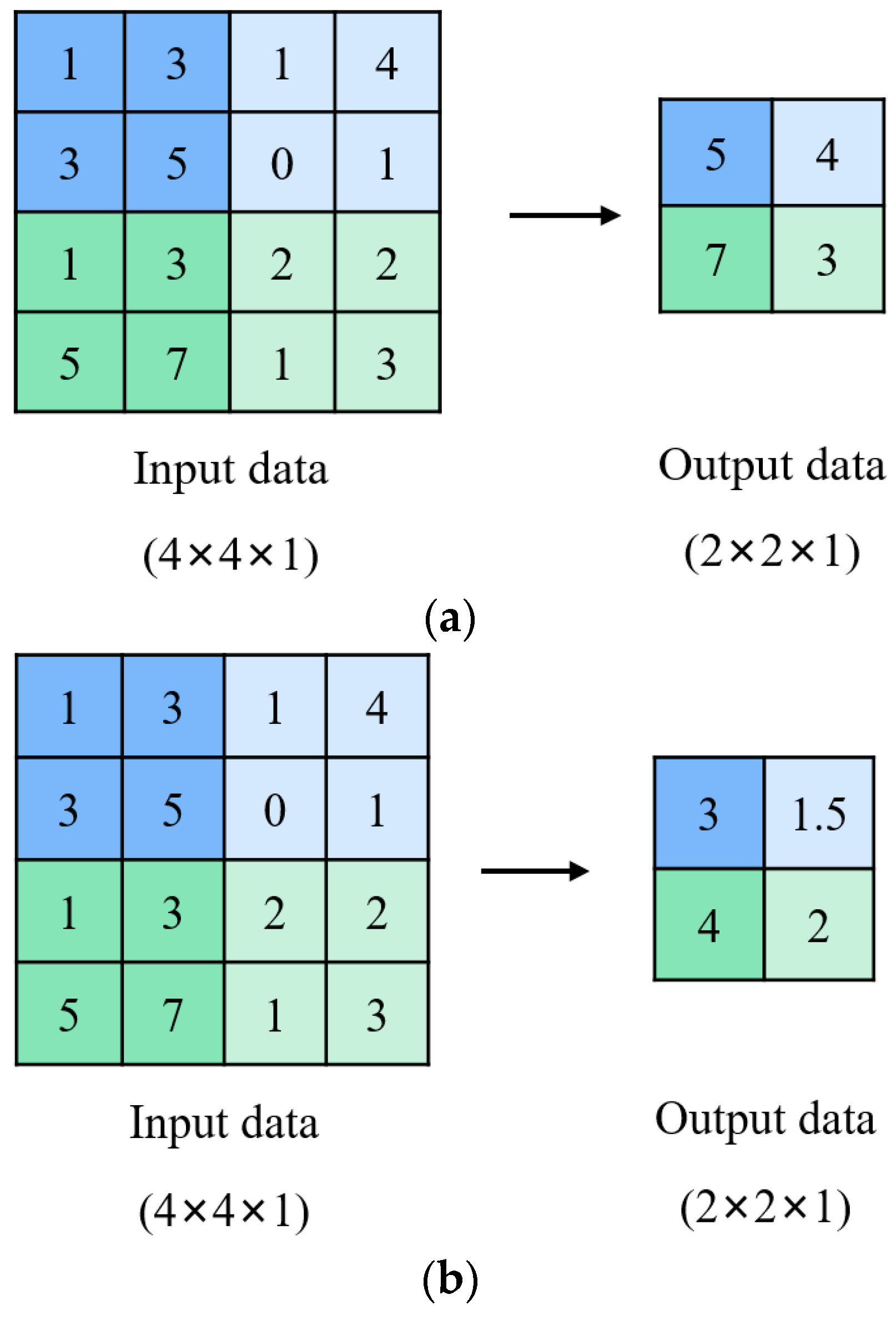
3.1. Concept of CNN
3.2. Model of CNN
3.2.1. Sample Obtaining
3.2.2. Structure of Neural Network Model
Model Building of CNN
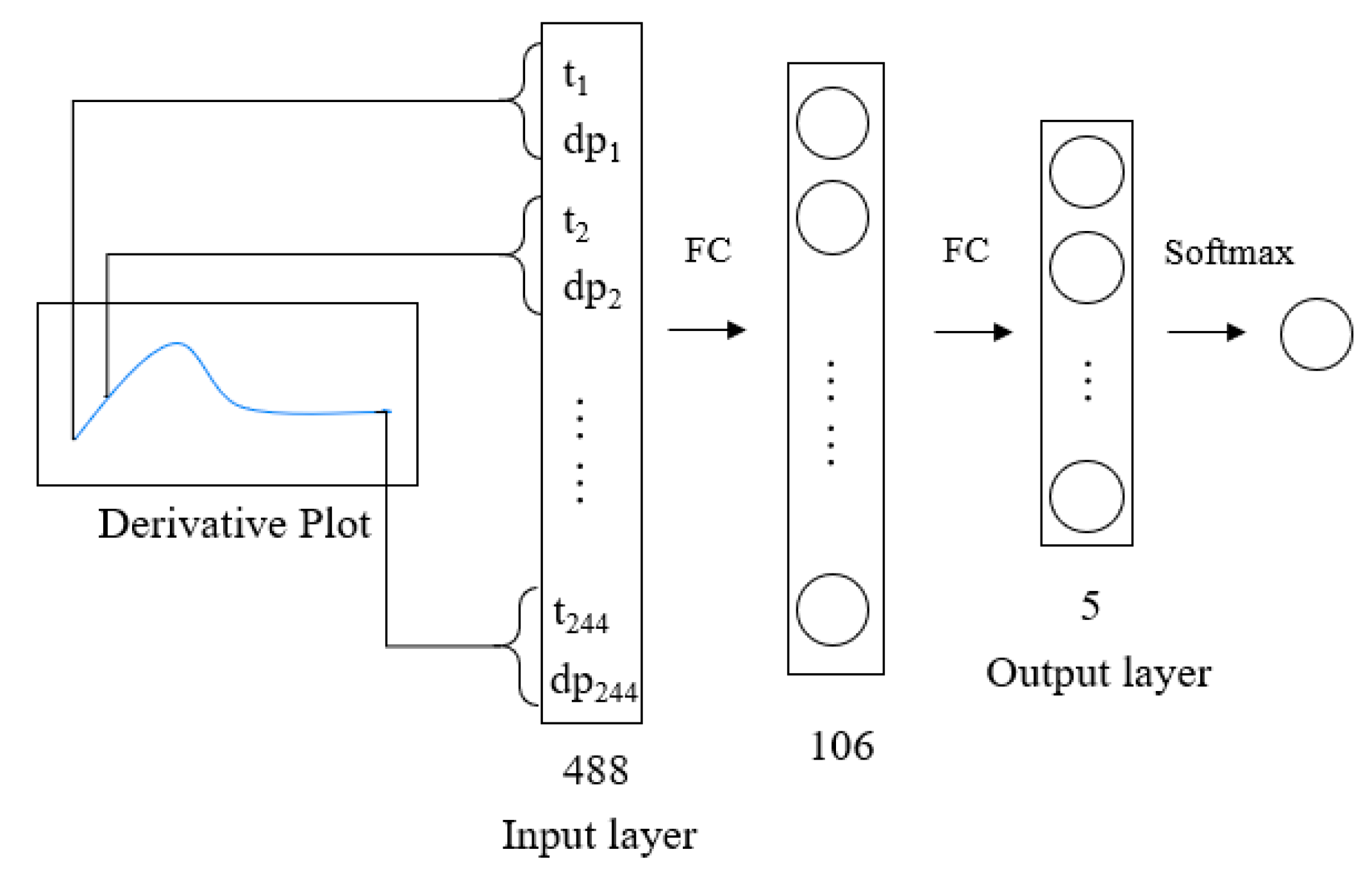
Model Building of FCNN
Evaluation Results for the CNN and FCNN
3.2.3. One-Hot Encoding
3.2.4. Determination of Model Initialization
3.2.5. Selection of Activation Functions
3.2.6. Regularization Technique
3.2.7. Adam Optimization Algorithm
3.2.8. Mini Batch Technique
4. Results and Discussions
4.1. Comparison of Classification Performance for FCNN and CNN
4.2. Effects of Parameters on Classification Results
4.2.1. Effect of the Learning Rate
4.2.2. Effect of the Dropout Rate
4.2.3. Effect of the Number of Training Samples
5. Conclusions
Author Contributions
Funding
Conflicts of Interest
Nomenclature
| Convolutional Neural Network | |||
| Fully Connected Neural Network | |||
| Convolutional Layer | |||
| Fully Connected Layer | |||
| One Dimensional | |||
| Two Dimensional | |||
| True Positive | |||
| False Positive | |||
| False Negative | |||
| Network Weight | |||
| Gradient | |||
| Number of Network Weight | |||
| Number of Iterative Step in Mini Batch Technique | |||
| Number of Training Samples in Mini Batch Technique | |||
| Number of Sample Classes | |||
| Sample Matrix | |||
| Real Sample Label Matrix | |||
| Predictive Sample Label Matrix | |||
| Output Value of Neural Network | |||
| Number of Training Samples | |||
| Greek | |||
| Learning Rate | |||
| , | Exponential Decay Rates in Adam Algorithm | ||
| , | Momentum in Adam Algorithm | ||
| Constant | |||
| L2 Regularization Parameter | |||
| Subscript | |||
| i-th Sample | |||
| j-th Feature | |||
| Iteration | |||
| Superscript | |||
| t-th Time Step | |||
Appendix A. Field Cases Used in This Work

| Thickness (m) | Porosity (%) | Permeability (mD) | Initial Pressure (MPa) | Wellbore Storage Coefficient | Skin Factor | Composite Radius (m) | Mobility Ratio | Dispersion Ratio | Fracture Half Length (m) | Omega | Lambda | Curve Type | |
|---|---|---|---|---|---|---|---|---|---|---|---|---|---|
| Case1 | 9.4 | 10.94 | 0.82 | 15.06 | 0.19 | 0.05 | / | / | / | 23.1 | / | / | 1 |
| Case2 | 9.56 | 13.12 | 0.02 | 13.56 | 0.12 | −5.88 | / | / | / | 59 | / | / | 1 |
| Case3 | 13.12 | 9.08 | 7.53 | 14.02 | 2.12 | 0.02 | / | / | / | 112 | / | / | 1 |
| Case4 | 5.68 | 11.04 | 0.5 | 17.2 | 0.01 | 0.01 | / | / | / | 76 | / | / | 1 |
| Case5 | 16 | 11.61 | 0.2 | 14.28 | 0.03 | 0.63 | / | / | / | 11.1 | / | / | 2 |
| Case6 | 4.3 | 13.68 | 0.41 | 10.29 | 0.6 | 0.11 | / | / | / | 46 | / | / | 2 |
| Case7 | 13.7 | 12.56 | 0.09 | 26.82 | 0.07 | 0.18 | / | / | / | 16.4 | / | / | 2 |
| Case8 | 9.7 | 10.8 | 1.14 | 20.05 | 1.96 | 0.26 | / | / | / | 128 | / | / | 2 |
| Case9 | 13.3 | 11.28 | 0.17 | 12.29 | 0.33 | 0.21 | / | / | / | 56.5 | / | / | 2 |
| Case10 | 8.5 | 11.77 | 1.08 | 22.61 | 0.12 | 0.3 | / | / | / | 126 | / | / | 2 |
| Case11 | 9.67 | 10.13 | 1 | 19.13 | 0.01 | 0.02 | / | / | / | / | 0.29 | 1.4 × 10⁻⁸ | 3 |
| Case12 | 10.78 | 13.03 | 0.27 | 40.55 | 0.07 | −0.81 | / | / | / | / | 0.08 | 9.4 × 10⁻⁴ | 3 |
| Case13 | 13.2 | 11.1 | 0.84 | 17.08 | 0.24 | −3.77 | 40.6 | 7.36 | 3.61 | / | / | / | 4 |
| Case14 | 5.4 | 12.3 | 0.34 | 13.47 | 0.16 | −4.58 | 12.3 | 7.71 | 12.8 | / | / | / | 4 |
| Case15 | 16.3 | 10.95 | 0.13 | 12.41 | 0.14 | −3.54 | 31 | 2.32 | 1.4 | / | / | / | 4 |
| Case16 | 11.6 | 13.12 | 0.25 | 16.02 | 0.15 | −3.64 | 31 | 2 | 3.06 | / | / | / | 4 |
| Case17 | 11.2 | 9.63 | 0.78 | 13.24 | 0.14 | −2.23 | 13.3 | 9.56 | 8.03 | / | / | / | 4 |
| Case18 | 8.2 | 11.25 | 0.25 | 20.87 | 0.15 | −2.82 | 33.26 | 0.82 | 0 | / | / | / | 5 |
| Case19 | 9.2 | 14.06 | 0.91 | 18.52 | 0.66 | −1.37 | 52.1 | 0.44 | 0 | / | / | / | 5 |
| Case20 | 27.2 | 13.12 | 0.4 | 24.64 | 0.32 | −1.72 | 13.9 | 0.36 | 0 | / | / | / | 5 |
| Case21 | 9.7 | 10.8 | 1.14 | 20.05 | 1.96 | 0.26 | 94.3 | 0.75 | 0.1 | / | / | / | 5 |
| Case22 | 8.2 | 13.36 | 0.42 | 25.82 | 0.89 | −3.78 | 59 | 0.51 | 0 | / | / | / | 5 |
| Case23 | 11.2 | 10.31 | 0.1 | 23.21 | 0.26 | −3.11 | 41 | 0.03 | 0 | / | / | / | 5 |
| Case24 | 7.3 | 14.6 | 1.35 | 24.68 | 0.61 | −3.56 | 92.2 | 0.72 | 0.01 | / | / | / | 5 |
| Case25 | 7.6 | 12.74 | 0.66 | 23.66 | 1.13 | −3.45 | 18.9 | 0.98 | 0 | / | / | / | 5 |
Appendix B. Infinite-Conductivity Vertically Fractured Model
Appendix C. Dual-Porosity Model with Pseudo-Steady State
Appendix D. Radial Composite Model
References
- Muskat, M. The flow of homogeneous fluids through porous media. Soil Sci. 1938, 46, 169. [Google Scholar] [CrossRef]
- Van Everdingen, A.F.; Hurst, W. The application of the Laplace transformation to flow problems in reservoirs. J. Pet. Technol. 1949, 1, 305–324. [Google Scholar] [CrossRef]
- Horner, D.R. Pressure build-up in wells. In Proceedings of the 3rd World Petroleum Congress, The Hague, The Netherlands, 28 May–6 June 1951. [Google Scholar]
- Ramey, H.J., Jr. Short-time well test data interpretation in the presence of skin effect and wellbore storage. J. Pet. Technol. 1970, 22, 97–104. [Google Scholar] [CrossRef]
- Gringarten, A.C.; Ramey, H.J., Jr.; Raghavan, R. Unsteady-state pressure distributions created by a well with a single infinite-conductivity vertical fracture. Soc. Pet. Eng. J. 1974, 14, 347–360. [Google Scholar] [CrossRef]
- Bourdet, D.; Ayoub, J.A.; Pirard, Y.M. Use of pressure derivative in well test interpretation. SPE Form. Eval. 1989, 4, 293–302. [Google Scholar] [CrossRef]
- Zhou, Q.; Dilmore, R.; Kleit, A.; Wang, J.Y. Evaluating gas production performances in Marcellus using data mining technologies. J. Nat. Gas. Sci. Eng. 2014, 20, 109–120. [Google Scholar] [CrossRef]
- Ma, Z.; Leung, J.Y.; Zanon, S.; Dzurman, P. Practical implementation of knowledge-based approaches for steam-assisted gravity drainage production analysis. Expert Syst. Appl. 2015, 42, 7326–7343. [Google Scholar] [CrossRef]
- Lolon, E.; Hamidieh, K.; Weijers, L.; Mayerhofer, M.; Melcher, H.; Oduba, O. Evaluating the relationship between well parameters and production using multivariate statistical models: A middle Bakken and three forks case history. In Proceedings of the SPE Hydraulic Fracturing Technology Conference, The Woodlands, TX, USA, 9–11 February 2016. [Google Scholar]
- Wang, S.; Chen, S. Insights to fracture stimulation design in unconventional reservoirs based on machine learning modeling. J. Pet. Sci. Eng. 2019a, 174, 682–695. [Google Scholar] [CrossRef]
- Wang, S.; Chen, Z.; Chen, S. Applicability of deep neural networks on production forecasting in Bakken shale reservoirs. J. Pet. Sci. Eng. 2019b, 179, 112–125. [Google Scholar] [CrossRef]
- Awoleke, O.; Lane, R. Analysis of data from the Barnett shale using conventional statistical and virtual intelligence techniques. SPE Reserv. Eval. Eng. 2011, 14, 544–556. [Google Scholar] [CrossRef]
- Chu, H.; Liao, X.; Zhang, W.; Li, J.; Zou, J.; Dong, P.; Zhao, C. Applications of Artificial Neural Networks in Gas Injection. In Proceedings of the SPE Russian Petroleum Technology Conference, Moscow, Russia, 15–17 October 2018. [Google Scholar]
- Akbilgic, O.; Zhu, D.; Gates, I.D.; Bergerson, J.A. Prediction of steam-assisted gravity drainage steam to oil ratio from reservoir characteristics. Energy 2015, 93, 1663–1670. [Google Scholar] [CrossRef]
- Al-Kaabi, A.U.; Lee, W.J. Using artificial neural networks to identify the well test interpretation model (includes associated papers 28151 and 28165). SPE Form. Eval. 1993, 8, 233–240. [Google Scholar] [CrossRef]
- Sultan, M.A.; Al-Kaabi, A.U. Application of neural network to the determination of well-test interpretation model for horizontal wells. In Proceedings of the SPE Asia Pacific Oil and Gas Conference and Exhibition, Melbourne, VIC, Australia, 8–10 October 2002. [Google Scholar]
- Kharrat, R.; Razavi, S.M. Determination of reservoir model from well test data, using an artificial neural network. Sci. Iran. 2008, 15, 487–493. [Google Scholar]
- AlMaraghi, A.M.; El-Banbi, A.H. Automatic Reservoir Model Identification using Artificial Neural Networks in Pressure Transient Analysis. In Proceedings of the SPE North Africa Technical Conference and Exhibition, Cairo, Egypt, 14–16 September 2015. [Google Scholar]
- Schroff, F.; Kalenichenko, D.; Philbin, J. Facenet: A unified embedding for face recognition and clustering. In Proceedings of the IEEE Conference on Computer Vision and Pattern Recognition, Boston, MA, USA, 7–12 June 2015; pp. 815–823. [Google Scholar]
- Redmon, J.; Divvala, S.; Girshick, R.; Farhadi, A. You only look once: Unified, real-time object detection. In Proceedings of the IEEE Conference on Computer Vision and Pattern Recognition, Las Vegas, NV, USA, 27–30 June 2016; pp. 779–788. [Google Scholar]
- Gatys, L.A.; Ecker, A.S.; Bethge, M. A neural algorithm of artistic style. arXiv 2015, arXiv:1508.06576. [Google Scholar] [CrossRef]
- He, K.; Zhang, X.; Ren, S.; Sun, J. Deep residual learning for image recognition. In Proceedings of the IEEE Conference on Computer Vision and Pattern Recognition, Las Vegas, NV, USA, 27–30 June 2016; pp. 770–778. [Google Scholar]
- Liu, D.; Li, Y.; Agarwal, R.K. Numerical simulation of long-term storage of CO2 in Yanchang shale reservoir of the Ordos basin in China. Chem. Geol. 2016, 440, 288–305. [Google Scholar] [CrossRef]
- Chu, H.; Liao, X.; Chen, Z.; Zhao, X.; Liu, W. Estimating carbon geosequestration capacity in shales based on multiple fractured horizontal well: A case study. J. Pet. Sci. Eng. 2019, 181, 106179. [Google Scholar] [CrossRef]
- Meng, X. Horizontal Fracture Seepage Model and Effective Way for Development of Chang 6 Reservoir. Ph.D. Thesis, Southwest Petroleum University, Chengdu, China, 2018. [Google Scholar]
- Chu, H.; Liao, X.; Chen, Z.; Zhao, X.; Liu, W.; Dong, P. Transient pressure analysis of a horizontal well with multiple, arbitrarily shaped horizontal fractures. J. Pet. Sci. Eng. 2019, 180, 631–642. [Google Scholar] [CrossRef]
- Jingli, Y.; Xiuqin, D.; Yande, Z.; Tianyou, H.; Meijuan, C.; Jinlian, P. Characteristics of tight oil in Triassic Yanchang formation, Ordos Basin. Pet. Explor. Dev. 2013, 40, 161–169. [Google Scholar]
- Hua, Y.A.N.G.; Jinhua, F.; Haiqing, H.; Xianyang, L.I.U.; Zhang, Z.; Xiuqin, D.E.N.G. Formation and distribution of large low-permeability lithologic oil regions in Huaqing, Ordos Basin. Pet. Explor. Dev. 2012, 39, 683–691. [Google Scholar]
- Li, Y.; Song, Y.; Jiang, Z.; Yin, L.; Luo, Q.; Ge, Y.; Liu, D. Two episodes of structural fractures: Numerical simulation of Yanchang Oilfield in the Ordos basin, northern China. Mar. Pet. Geol. 2018, 97, 223–240. [Google Scholar] [CrossRef]
- Guo, P.; Ren, D.; Xue, Y. Simulation of multi-period tectonic stress fields and distribution prediction of tectonic fractures in tight gas reservoirs: A case study of the Tianhuan Depression in western Ordos Basin, China. Mar. Pet. Geol. 2019, 109, 530–546. [Google Scholar] [CrossRef]
- Krizhevsky, A.; Sutskever, I.; Hinton, G.E. Imagenet classification with deep convolutional neural networks. In Proceedings of the 25th International Conference on Neural Information Processing Systems, Lake Tahoe, NV, USA, 3–6 December 2012; pp. 1097–1105. [Google Scholar]
- Glorot, X.; Bengio, Y. Understanding the difficulty of training deep feedforward neural networks. In Proceedings of the Thirteenth International Conference on Artificial Intelligence and Statistics, Sardinia, Italy, 13–15 March 2010; pp. 249–256. [Google Scholar]
- Ghaderi, A.; Shahri, A.A.; Larsson, S. An artificial neural network based model to predict spatial soil type distribution using piezocone penetration test data (CPTu). Bull. Eng. Geol. Environ. 2018, 1–10. [Google Scholar] [CrossRef]
- Kingma, D.P.; Ba, J. Adam: A method for stochastic optimization. arXiv 2014, arXiv:1412.6980. [Google Scholar]
- Chen, X.; Liu, S.; Sun, R.; Hong, M. On the convergence of a class of adam-type algorithms for non-convex optimization. arXiv 2018, arXiv:1808.02941. [Google Scholar]
- Reddi, S.J.; Kale, S.; Kumar, S. On the convergence of adam and beyond. arXiv 2019, arXiv:1904.09237. [Google Scholar]
- Mukhanov, A.; Arturo Garcia, C.; Torres, H. Water Control Diagnostic Plot Pattern Recognition Using Support Vector Machine. In Proceedings of the SPE Russian Petroleum Technology Conference, Moscow, Russia, 15–17 October 2018. [Google Scholar]
- Hamdia, K.M.; Silani, M.; Zhuang, X.; He, P.; Rabczuk, T. Stochastic analysis of the fracture toughness of polymeric nanoparticle composites using polynomial chaos expansions. Int. J. Fract. 2017, 206, 215–227. [Google Scholar] [CrossRef]
- Shahri, A.A.; Asheghi, R. Optimized developed artificial neural network-based models to predict the blast-induced ground vibration. Innov. Infrastruct. Solut. 2018, 3, 34. [Google Scholar] [CrossRef]
- Saltelli, A.; Ratto, M.; Andres, T.; Campolongo, F.; Cariboni, J.; Gatelli, D.; Saisana, G.; Tarantola, S. Global Sensitivity Analysis: The Primer; John Wiley & Sons: Chichester, UK, 2008; ISBN 9780470725184. [Google Scholar]
- Saltelli, A. Sensitivity analysis for importance assessment. Risk Anal. 2002, 22, 579–590. [Google Scholar] [CrossRef]
- Vu-Bac, N.; Lahmer, T.; Zhuang, X.; Nguyen-Thoi, T.; Rabczuk, T. A software framework for probabilistic sensitivity analysis for computationally expensive models. Adv. Eng. Soft. 2016, 100, 19–31. [Google Scholar] [CrossRef]
- Shahri, A.A. An optimized artificial neural network structure to predict clay sensitivity in a high landslide prone area using piezocone penetration test (CPTu) data: A case study in southwest of Sweden. Geotech. Geol. Eng. 2016, 34, 745–758. [Google Scholar] [CrossRef]
- Chen, Z.; Liao, X.; Sepehrnoori, K.; Yu, W. A Semianalytical Model for Pressure-Transient Analysis of Fractured Wells in Unconventional Plays With Arbitrarily Distributed Discrete Fractures. SPE J. 2018, 23, 2041–2059. [Google Scholar] [CrossRef]
- Chen, Z.; Liao, X.; Zhao, X.; Lyu, S.; Zhu, L. A comprehensive productivity equation for multiple fractured vertical wells with non-linear effects under steady-state flow. J. Pet. Sci. and Eng. 2017, 149, 9–24. [Google Scholar] [CrossRef]
- Zongxiao, R.; Xiaodong, W.; Dandan, L.; Rui, R.; Wei, G.; Zhiming, C.; Zhaoguang, T. Semi-analytical model of the transient pressure behavior of complex fracture networks in tight oil reservoirs. J. Nat. Gas Sci. Eng. 2016, 35, 497–508. [Google Scholar] [CrossRef]


| Model | 1 | 2 | 3 | 4 | 5 |
|---|---|---|---|---|---|
| Wellbore storage coefficient (m3/MPa) | 0–0.25 | 0–0.25 | 0–0.25 | 0–0.25 | 0–0.25 |
| Skin factor | 0–0.05 | 0.05–2 | 0–1 | 0–1 | 0–1 |
| Fracture half length (m) | 20–80 | 20–80 | / | / | / |
| Initial pressure (MPa) | 15–35 | 15–35 | 15–35 | 15–35 | 15–35 |
| Permeability (mD) | 0.10–50 | 0.10–50 | 0.10–50 | 0.10–50 | 0.10–50 |
| Thickness (m) | 9.14 | 9.14 | 9.14 | 9.14 | 9.14 |
| Porosity | 0.10 | 0.10 | 0.10 | 0.10 | 0.10 |
| Omega | / | / | 0.01–0.60 | / | / |
| lambda | / | / | 10−6–10−9 | / | / |
| Mobility ratio | / | / | / | 1–20 | 0–1 |
| Dispersion ratio | / | / | / | 1–20 | 0–1 |
| Composite radius (m) | / | / | / | 10–200 | 10–200 |
| Layer | Layer Shape (Output Shape) | Weights Number |
|---|---|---|
| Input | (2,244) | 0 |
| Conv1D | (38,80) | 418 |
| Max-Pooling1D | (38,38) | 0 |
| Conv2D | (17,17,64) | 1664 |
| Max-Pooling2D | (5,5,64) | 0 |
| Conv2D | (2,2,128) | 73856 |
| Average-Pooling2D | (1,1,128) | 0 |
| Flatten | 128 | 0 |
| FC (Output) | 5 | 645 |
| Layer | Layer Shape (Output Shape) | Weights Number |
|---|---|---|
| Input | 488 | 0 |
| FC | 106 | 75,795 |
| FC (Output) | 5 | 780 |
| Class1 | Class2 | Class3 | Class4 | Class5 | |
|---|---|---|---|---|---|
| Sample1 | 0 | 1 | 0 | 0 | 0 |
| Sample2 | 1 | 0 | 0 | 0 | 0 |
| Sample3 | 0 | 0 | 1 | 0 | 0 |
| …………. | |||||
| Sample2724 | 0 | 0 | 1 | 0 | 0 |
| Sample2725 | 0 | 0 | 0 | 0 | 1 |
| Type | Equation |
|---|---|
| linear | |
| tanh | |
| sigmoid | |
| ELU | |
| ReLU |
| Loss Function | Accuracy (%) | |
|---|---|---|
| CNN train set | 0.19 | 96.6 |
| CNN validation set | / | 95.6 |
| FCNN train set | 0.44 | 91.2 |
| FCNN validation set | / | 89.8 |
| Model | Index | Class1 | Class2 | Class3 | Class4 | Class5 | Score |
|---|---|---|---|---|---|---|---|
| FCNN | Precision (%) | 92.94 | 86.71 | 88.72 | 91.32 | 96.07 | 0.83 |
| Recall (%) | 92.20 | 82.20 | 91.20 | 92.60 | 97.80 | ||
| F1Score | 0.93 | 0.84 | 0.90 | 0.92 | 0.97 | ||
| CNN | Precision (%) | 97.25 | 97.00 | 96.64 | 94.34 | 97.83 | 0.93 |
| Recall (%) | 99.00 | 90.60 | 97.80 | 96.60 | 99.00 | ||
| F1Score | 0.98 | 0.94 | 0.97 | 0.95 | 0.98 |
| Model | Index | Class1 | Class2 | Class3 | Class4 | Class5 | Score |
|---|---|---|---|---|---|---|---|
| FCNN | Precision (%) | 97.50 | 78.57 | 97.83 | 76.92 | 100 | 0.81 |
| Recall (%) | 86.67 | 73.33 | 100 | 88.89 | 100 | ||
| F1Score | 0.92 | 0.76 | 0.99 | 0.82 | 1.00 | ||
| CNN | Precision (%) | 100 | 95.35 | 95.56 | 91.49 | 95.74 | 0.91 |
| Recall (%) | 95.56 | 91.11 | 95.56 | 95.56 | 100 | ||
| F1Score | 0.97 | 0.93 | 0.96 | 0.93 | 0.98 |
| Index | Model 1 | Model 2 | Model 3 | Model 4 | Model 5 | Score |
|---|---|---|---|---|---|---|
| Recall | 75 | 83.3 | 100 | 80 | 87.5 | 0.69 |
| Precision | 100 | 71.4 | 66.7 | 80 | 100 | |
| F1Score | 0.86 | 0.77 | 0.80 | 0.80 | 0.93 |
© 2019 by the authors. Licensee MDPI, Basel, Switzerland. This article is an open access article distributed under the terms and conditions of the Creative Commons Attribution (CC BY) license (http://creativecommons.org/licenses/by/4.0/).
Share and Cite
Chu, H.; Liao, X.; Dong, P.; Chen, Z.; Zhao, X.; Zou, J. An Automatic Classification Method of Well Testing Plot Based on Convolutional Neural Network (CNN). Energies 2019, 12, 2846. https://doi.org/10.3390/en12152846
Chu H, Liao X, Dong P, Chen Z, Zhao X, Zou J. An Automatic Classification Method of Well Testing Plot Based on Convolutional Neural Network (CNN). Energies. 2019; 12(15):2846. https://doi.org/10.3390/en12152846
Chicago/Turabian StyleChu, Hongyang, Xinwei Liao, Peng Dong, Zhiming Chen, Xiaoliang Zhao, and Jiandong Zou. 2019. "An Automatic Classification Method of Well Testing Plot Based on Convolutional Neural Network (CNN)" Energies 12, no. 15: 2846. https://doi.org/10.3390/en12152846
APA StyleChu, H., Liao, X., Dong, P., Chen, Z., Zhao, X., & Zou, J. (2019). An Automatic Classification Method of Well Testing Plot Based on Convolutional Neural Network (CNN). Energies, 12(15), 2846. https://doi.org/10.3390/en12152846