1. Introduction
Electrical machines condition monitoring is a scientific area that includes two individual areas, namely the fault diagnosis and fault prognosis. The former deals with the detection of faults that have happened in the electrical machine, while the latter deals with the estimation of the machine’s remaining useful life through proper modeling of the degradation mechanisms. The two areas have different approaches and philosophies and typically work in a complimentary manner.
Regarding the fault diagnosis in electrical machines, the literature is very rich, although most papers deal with induction motors due to their importance for industrial applications. However, synchronous generators are very critical devices and are typically much larger than induction motors so if a catastrophic failure happens to them, it can lead to huge financial losses and other negative impacts. The exact impact of an undetected fault that leads to a catastrophic machine breakdown depends on the machine’s rating and application [
1].
Modern diagnostic demands require not only the discrimination between a healthy and a faulty machine state but also reliable fault identification and estimation of the fault’s severity level to allow for maintenance actions and service planning.
The main application of salient-pole synchronous machines is for hydro energy as well as smaller sized power production in industry. Typically, such generators operate uninterrupted for extended periods before they are subjected to maintenance [
2]. There are three types of faults: electrical, magnetic and mechanical [
3]. Among those, the mechanical failures are the most frequently expected faults [
4]. Mechanical failures include the eccentricity fault and bearing faults. The eccentricity fault is a condition where the electrical machine operates under an asymmetrical air-gap due to displacement of the rotor. The eccentricity fault may be either static when the rotor’s dislocation is fixed in space and time, or dynamic when the rotor geometric center changes continuously over time. If the two conditions co-exist, then this is known as the mixed eccentricity condition [
5].
The static eccentricity fault usually appears at the commissioning stages and starts as a manufacturing fault. It can be caused by improper alignment of the shaft or the stator inner ovality. Some level of inherent eccentricity is expected, however, and this is due to the very small air-gap between the rotor poles and the stator teeth [
6]. The impact of the rotor weight affects the level of the static eccentricity in large electrical machines over time.
The impact of eccentricity on synchronous machines has been studied in the past [
6,
7,
8,
9]. The radial and tangential forces are known to increase in the presence of eccentricity conditions [
7]. It has been presented in reference [
8] that variation of the air-gap magnetic reluctance will generate eddy currents in the rotor damping cage, even at unloaded operation [
8]. A paper on the Unbalanced Magnetic Pull (UMP) caused by eccentricity faults in synchronous machines presented the independence between the static and dynamic eccentricity [
6]. Finally, it was shown that the impact of the damper cage in case of eccentric conditions is very weak, an attribute associated with its high ohmic resistance [
9]. However, the damper cage’s impact on the forces due to the eccentricity fault is small, an attribute due to the cage’s high ohmic resistance.
Moreover, focusing on the actual diagnosis of the eccentricity fault in synchronous machines, it is clear that most past works focus on either permanent magnet [
10,
11,
12,
13] or reluctance machines [
14,
15,
16], while literature is very limited for salient pole ones. Despite this unequal research effort, some contributions have been identified and are listed here. Intrusive techniques such as the installation of flux sensors to capture the air-gap magnetic flux give good results [
17]. Alternatively, it has been proposed to monitor the shaft voltage at a steady state [
18,
19]. However the reliability of this method is questionable. Furthermore, the no-load induced stator voltage’s spectra [
20] and space vector [
21] have been applied. In reference [
22] an off-line technique is proposed, based on the standard short-circuit test, where the line currents are subjected to spectral analysis and their higher harmonic index is studied. Moreover, a satisfying approach is shown in references [
23,
24] where the Split-Phase Currents method is presented.
In this paper, a new reliable method is proposed for the detection of static eccentricity in 3-phase synchronous generators. The main advantage of the proposed method is its simplicity, low cost and non-intrusiveness. The technique relies on the monitoring of the three phase currents of the generator under locked rotor conditions for three rotor positions. The monitored signals are used to calculate a pseudo Zero-Sequence Current (ZSC) waveform. The spectra of this signal has been proven to be a reliable way to detect not only the static eccentricity fault but also its severity level. The method can replace the existing practices in the field by utilizing wedges to measure the eccentricity, and more importantly offers a solution for generator cases that are difficult to disassemble due to their cooling mechanisms, which prevent the use of wedges. More importantly, the proposed method can be applied in any 3-phase wound rotor synchronous generator, since it relies on the impact of saturation inflicted by the static eccentricity fault. Finally, its value on the discrimination of the static eccentricity fault from the mixed eccentricity conditions typically monitored by other on-line methods is profound, since it will suggest a more accurate maintenance plan by technical crews.
2. Description of the Proposed Method: Pseudo Zero Sequence Current
When an electrical machine has static eccentricity, then the rotor’s irregular position in the stator is fixed in space, thus creating an asymmetry of the air-gap reluctance which is only spatial and not time varying.
Furthermore, this means that at every instant a certain salient pole will be closer to the stator iron core while its symmetrical salient pole at 180° apart has a maximum distance from the stator. This condition affects the spatial distribution of the magnetic flux.
More specifically, the salient pole at the side of the eccentricity displacement will drive more flux lines to the stator core due to the local decreased air-gap reluctance. However, this means that locally the iron teeth of the stator and this specific rotor pole will experience the impact of local flux increase due to the fault.
The synchronous generators’ stator windings are typically connected in star. So, for the purposes of this method, the stator 3-phase winding is connected to a symmetrical sinusoidal supply. It is important not to forget that the rotor is in locked position, so there is an absence of back-EMF. Thus, the supply voltage has to remain low in order to avoid high currents in the stator winding. In general, such methods with the rotor being locked should be applied to machines fed by less than 20% the nominal voltage.
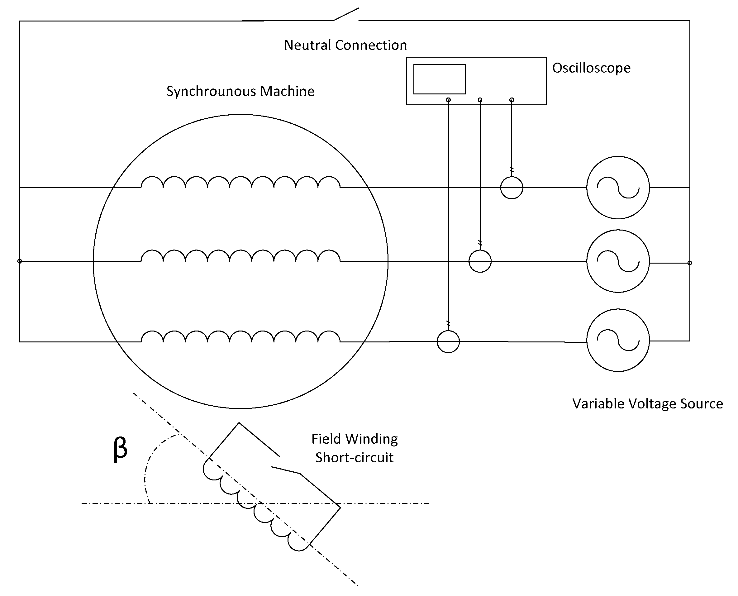
The electric circuit under the testing conditions is illustrated in
Figure 1. The rotor field winding could be in either open or shorted condition. If open, then there is no electrical impact from the rotor. On the other hand, if the rotor winding is shorted, it resembles an induction machine and thus the rotating magnetic field of the stator will induce eddy currents in the field winding. Furthermore, since the stator winding is in star, there is a question of whether the neutral point will be connected or not connected to that of the supply.
Finally, the initial rotor position (unknown to the diagnostic engineer) could influence the measurements, as the magnetic behavior of the machine when a pole is across the maximum of the rotating magnetic field is different to when the maximum of the field is across the maximum air-gap condition. This parameter is also taken into account in
Figure 1 by the use of the angle β.
The current value in this test depends on the relative to the stator, rotor position. In case of minimum air gap, that is the pole is in front of the phase, the phase current will be minimum. On the other hand, if the air gap is at its maximum, the phase current should be also at its maximum. The variation in the reluctance, produced by the rotation of the rotor, is clearly seen in the magnetization current. Moreover, as explained before, eccentricity also modifies the reluctance. The main objective of this method is to measure the excitation current at three different equivalent positions in each phase, in ideal case without eccentricity, the currents should be equal, but in case of eccentricity, the currents will be different.
Pseudo Zero Sequence Subsection
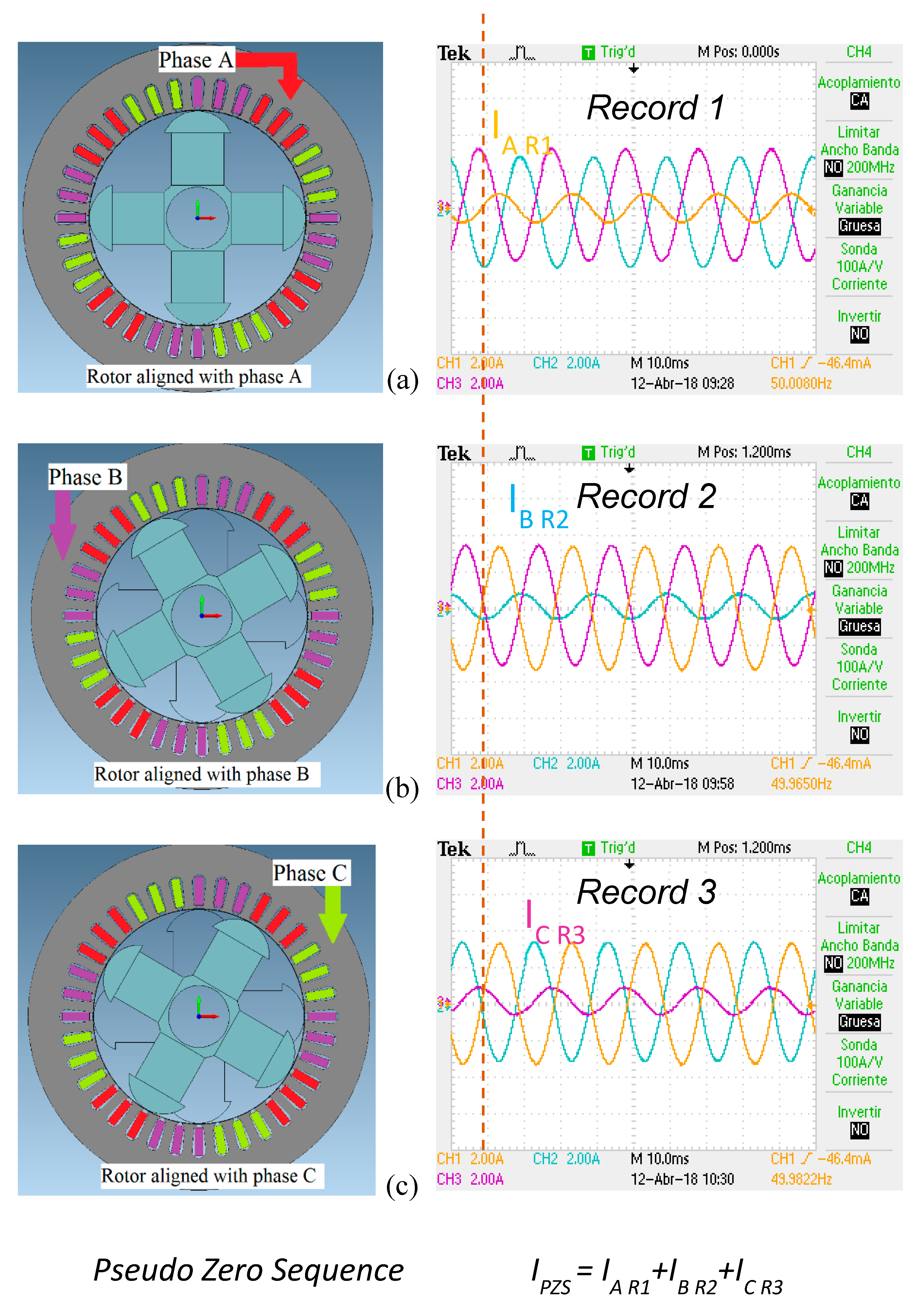
The main idea behind the proposed method is that the spatial air-gap irregularity caused by the static eccentricity spatially affects the electrical machine. So, more than one sensing local points are required. For this purpose, all three phase currents are monitored at a specific rotor position while the rotor is locked.
Afterwards, the rotor is manually shifted by 120 electrical degrees and the measurement is repeated. And finally the rotor is shifted by another 120 electrical degrees and the phase current waveforms are captured again.
The first second and third phase currents are stored from records 1, 2 and 3, as shown in
Figure 2. In order to obtain the pseudo zero sequence (I
PZS), it is necessary to add the phase A of the first record (I
A R1) to the phase B (I
B R2) of the second record and to the phase C (I
C R3) of the third record. It is important that the three records should recorded with a trigger in one phase. For example, in the
Figure 2 it can be observed than the phase A is zero in the three records at the same time (see the dotted line).
It is remarkable that in the example presented in
Figure 2, the phase current in the phases used for the method is at the minimum level. This is due to the pole being aligned to the phases when the records have been taken.
Under healthy conditions, the three captured currents should be the same because the rotor shift by 120 electrical degrees leads to a non-change of the air-gap reluctance. As a consequence, their sum, which is a pseudo zero-sequence current, will result in a signal which is iron core non linearity dependent and which will have a fundamental frequency equal to 3 times the supply one. However, if a static eccentricity fault exists, then the third harmonic will be increased due to the different current in the equivalent positions described earlier and this is the main indication of the fault existence and severity.
3. Finite Element Analysis
To have a closer look to the magnetic field behavior under healthy and eccentric state, an investigation took place using the Finite Element Analysis.
The machine used in this work has parameters shown in
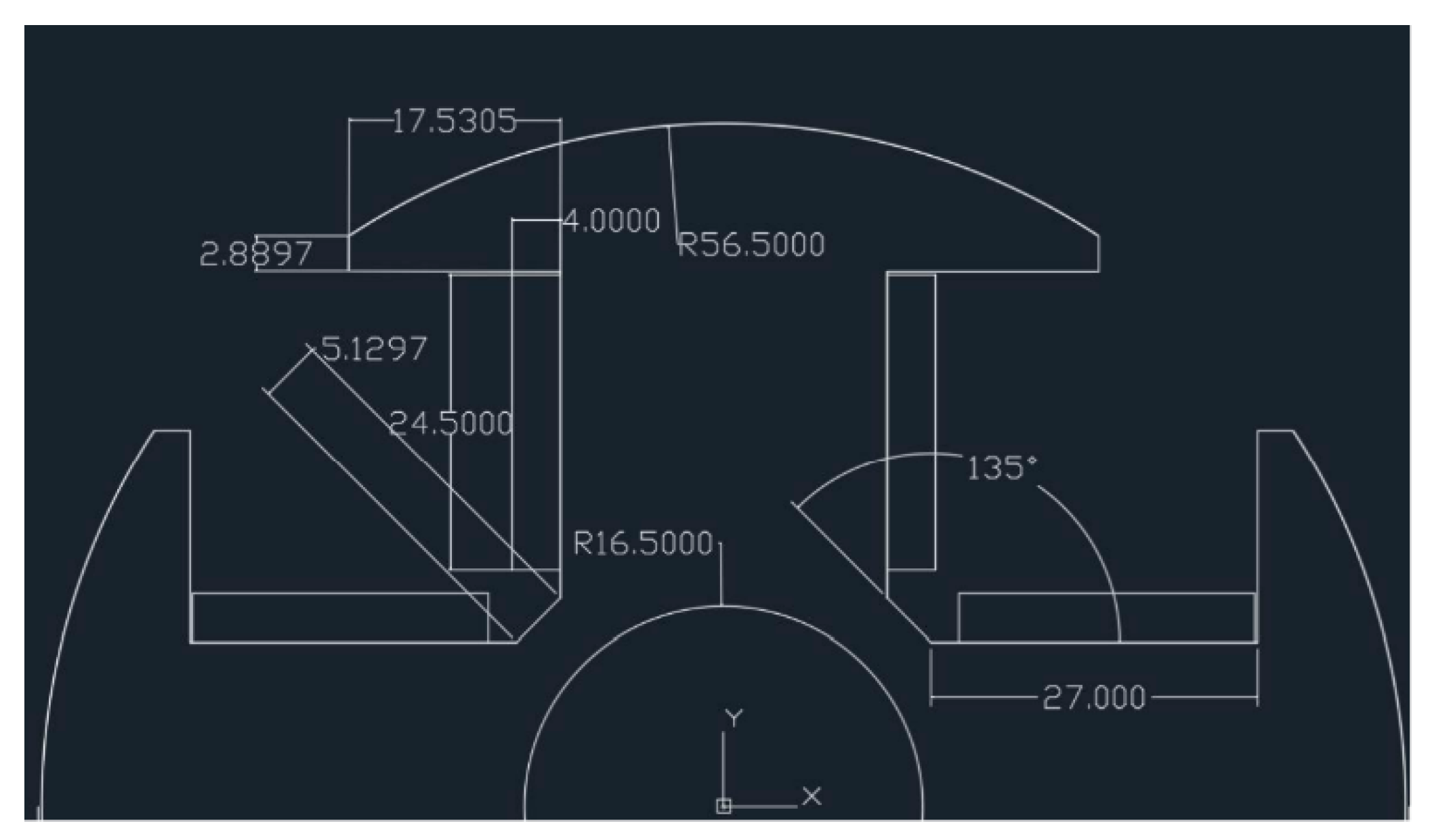
Table 1. The designed machine’s rotor blueprints are shown in
Figure 3. The outer radius of the stator is 92.5 mm while the stator slot number is 36.
The level of the static eccentricity fault severity was kept deliberately low and equal to 20%.
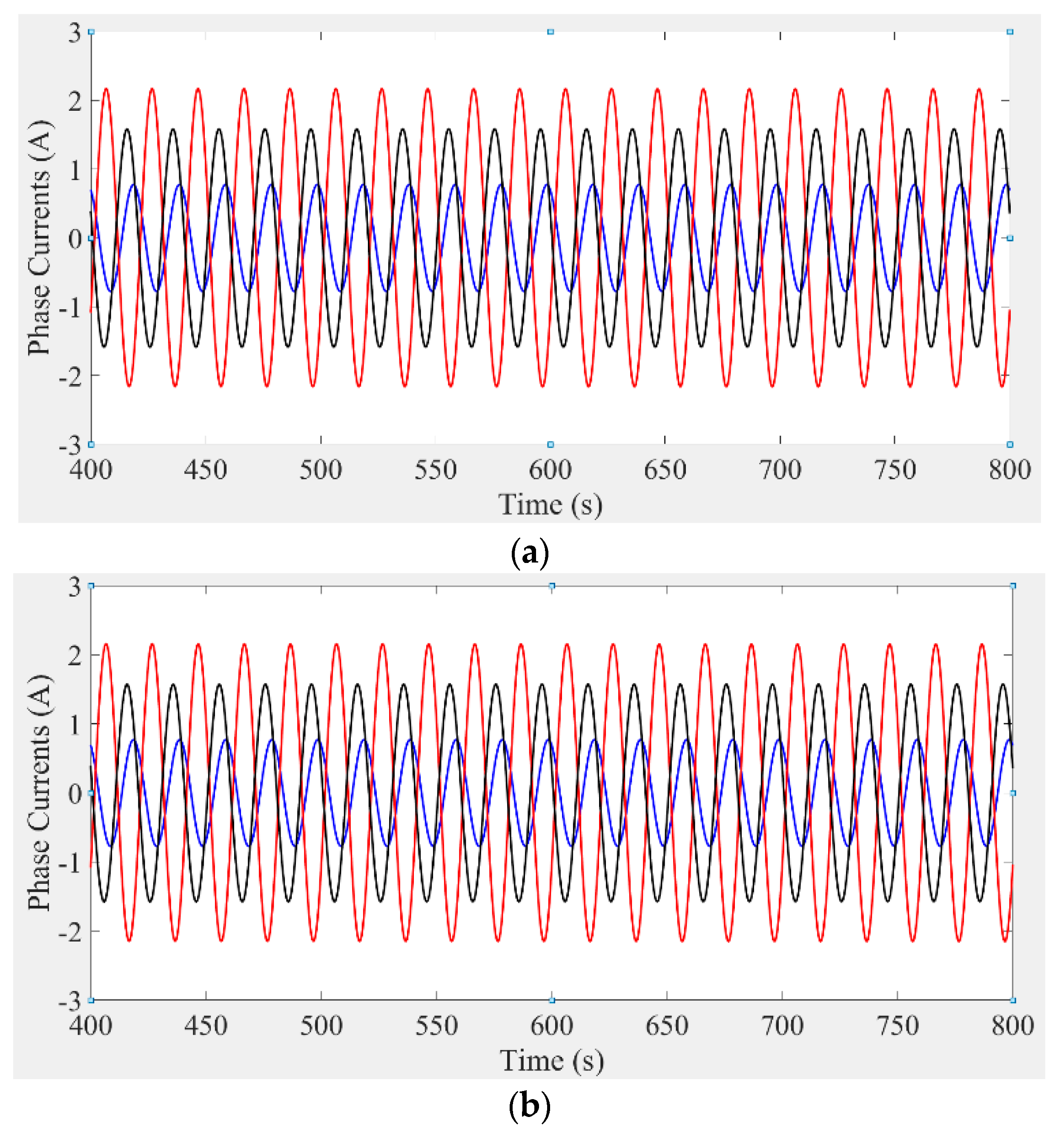
Figure 4 presents the three phase currents as captured for a specific rotor position under healthy and faulty state (20% severity). The three phase currents are of course asymmetrical because their amplitude and phase depend on the instantaneous rotor position with respect to the stator. However, no noticeable difference was observed between the healthy and faulty machines. For this purpose, the magnetic flux density distribution was be studied at the initial rotor position.
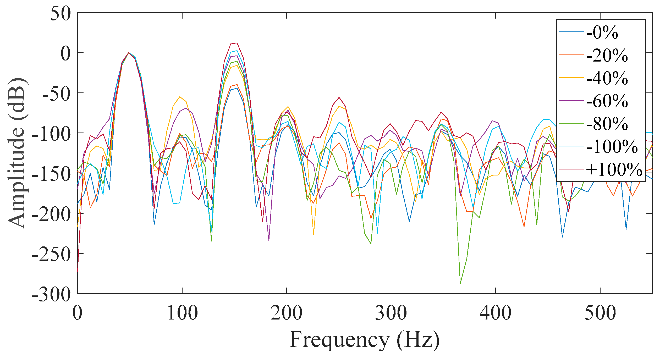
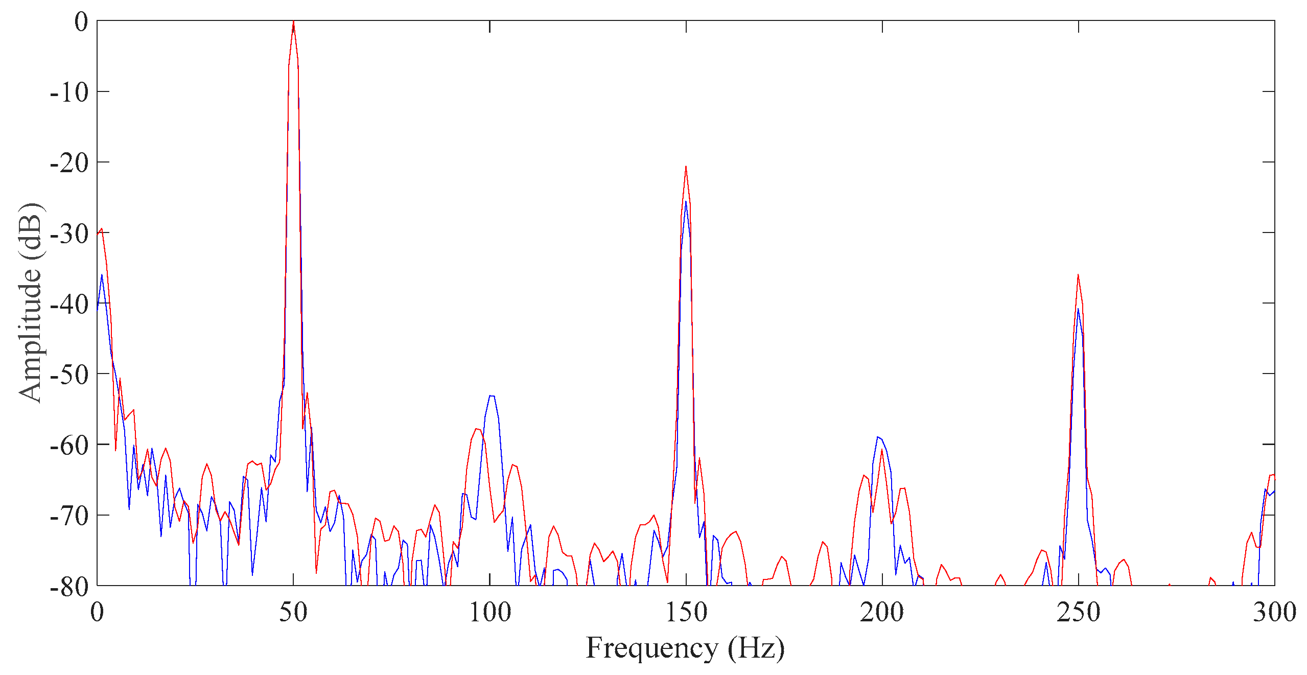
The application of the proposed method led to the calculation of the following spectra as shown in
Figure 5 below. It is clear that the third harmonic’s amplitude increased in the faulty machine and the amplitude difference was approximately 5 dB. A similar amplitude increase was observed in the fifth harmonic as well.
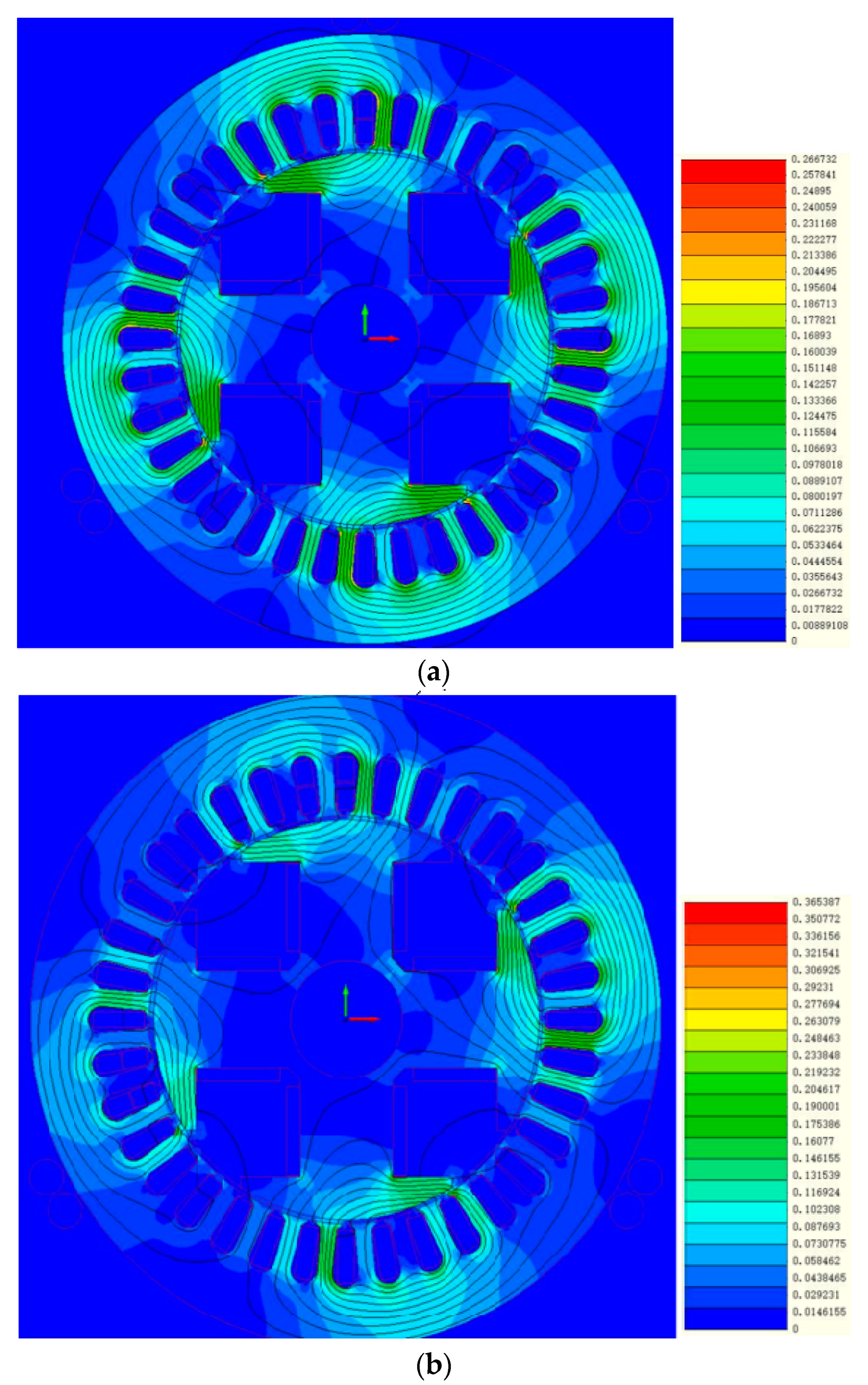
The magnetic flux density distribution at initial position for a healthy and faulty machine is shown in
Figure 6. The asymmetry of the magnetic flux density distribution due to the fault can be easily recognized. From the asymmetrical distribution, it is clear that the rotor has been shifted to the right, while the right pole has a significantly higher magnetic flux density than the other three.
More importantly though, the maximum of the magnetic flux density appears to have significantly increased in the faulty machine. To be specific, in the healthy machine is the increase was approximately 0.267 T and in the eccentric machine it was 0.365 T.
4. Experimental Results and Analysis
At the early stages of this investigation, it was noted that the proposed method for eccentricity testing can be applied in salient-pole synchronous machines by at least eight different combinations, which depend on the following aspects:
Initial relative position of the rotor with respect to the stator.
Field winding status (Short-circuit or open-circuit).
Neutral point connection.
4.1. Initial Position of the Rotor
The current value in the eccentricity tests strongly depends on the relative to the stator, rotor position. If the air gap is minimum (that is when the salient pole is across the activated phase) in front of the activated phase winding, the phase current will be minimum in the phase winding as well. On the other hand, if the air gap is maximum the phase current should be also maximum in this phase winding. This is obviously due to the effect of the magnetic reluctance, which significantly increases in the case of a maximum air gap. For this reason, the results on the eccentricity tests were not the same as when the initial rotor position changed. Therefore the two extremes cases, maximum and minimum stator current were considered in this investigation.
4.2. Connection of the Neutral Points
The windings of the synchronous machines, especially the generators, were connected in Y. Thus, we had the ability to connect the neutral point of the variable voltage source to the neutral of the machine. Therefore, two more cases were investigated and used to deal with the neutral connection. It is to be noted at this point that the main difference between the two connections was the formation of the zero-sequence current, as well as the phase difference of the 3-phase triplets to their respective fundamentals.
4.3. Field Winding Status (Short-Circuit or Open-Circuit)
The field winding of the synchronous machine could be open or in short-circuit condition. In the second case, eddy currents will flow in the rotor winding due to the rotating magnetic field, whereas in the first case, the rotor is magnetically passive to the stator. When the field winding is shorted then the behavior of the machine emulates that of an induction motor.
4.4. Experimental Setup
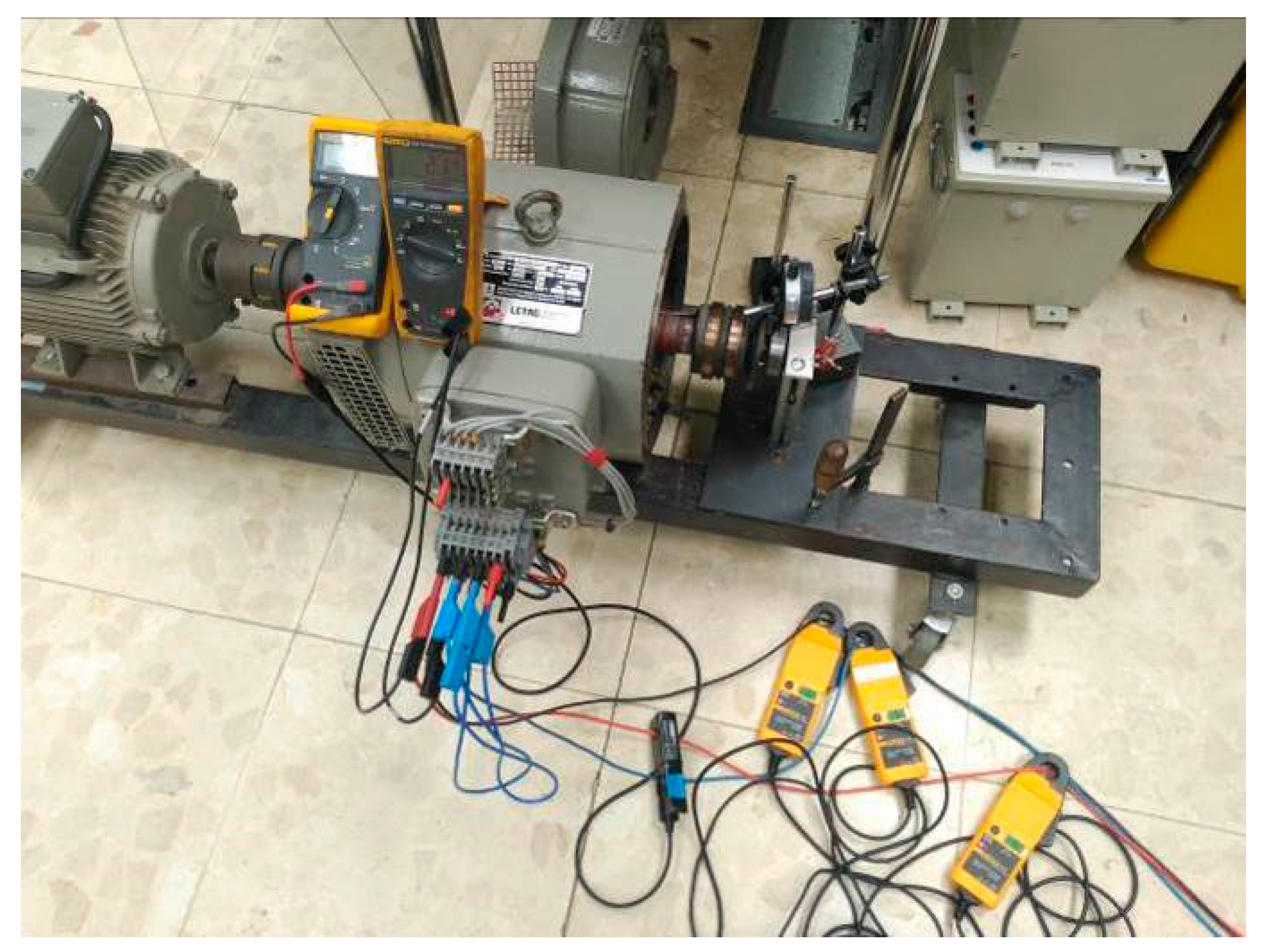
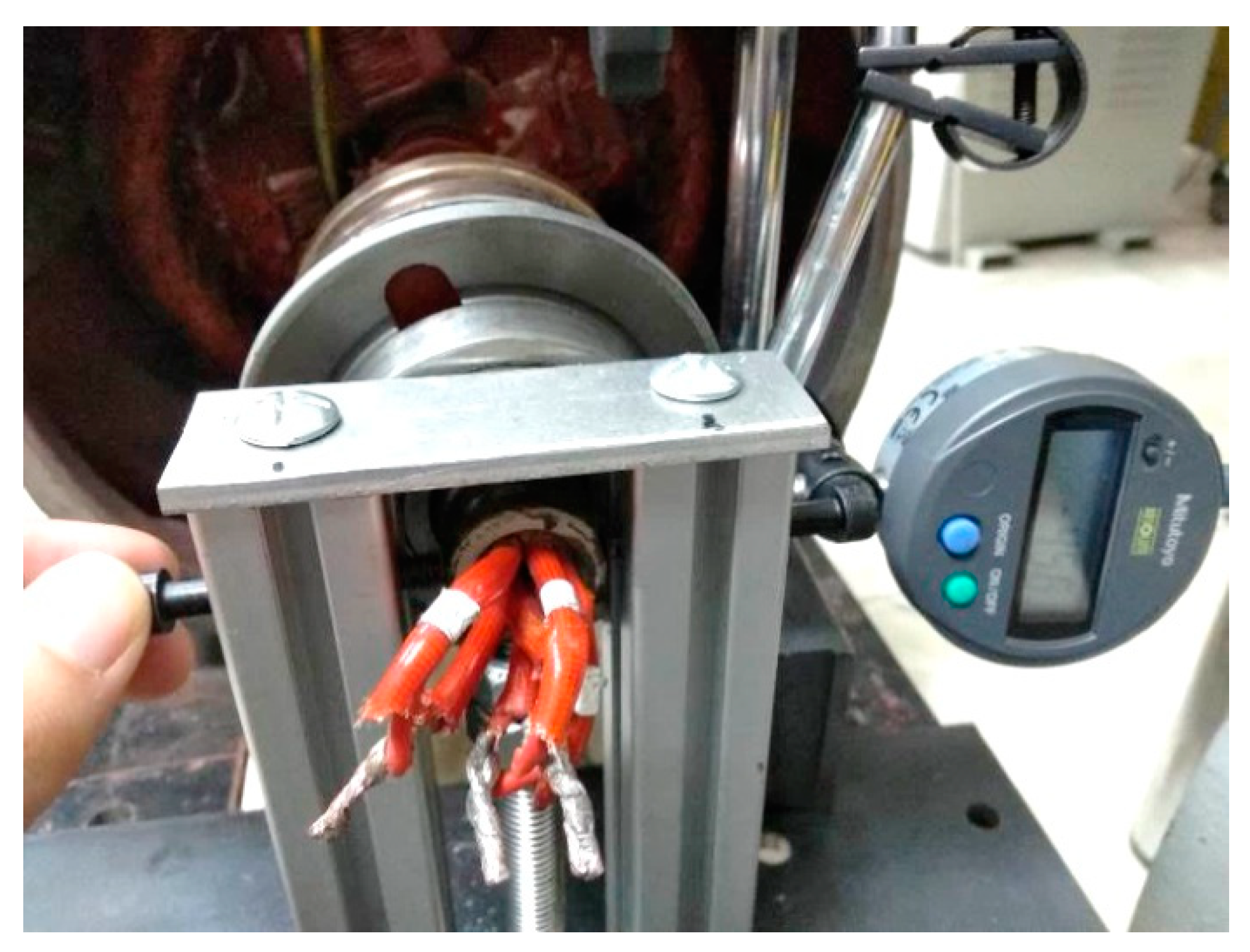
In order to create the eccentricity fault, one side cover of the generator was completely removed in order to allow access to the shaft in the non-drive end. A contrumption based on two steel columns and a system of 3 skrews has been installed to allow the rotor displacement at desired positions. A comparator watch has been installed to provide an indication of the severity level of the eccentric displacement (
Figure 7). The severity level is the rotor centre displacement from the stator’s geometrical centre over the air-gap length so it is dimensionless and usually presented in % values. Hall-effect current sensors are used to monitor the stator currents with an error of ±2 mA for sampling frequencies up to 20 MHz (
Figure 8). The monitored signals are stored with the use of a 4-channel digital (100 MHz bandwidth, 2 GS/s sample rate).
4.5. Experimental Testing and Results
In conclusion we had eight different ways to carry out the proposed testing methodology, as presented in
Table 2.
Furthermore, the salient pole generator was monitored under healthy and various faulty conditions. The static eccentricity fault severity levels were set to 20%, 40%, 60%, 80% and 100%. All of the above investigating conditions were considered and the respective results of the eccentricity tests are presented for the different cases in
Figure 9,
Figure 10,
Figure 11,
Figure 12,
Figure 13,
Figure 14,
Figure 15 and
Figure 16.
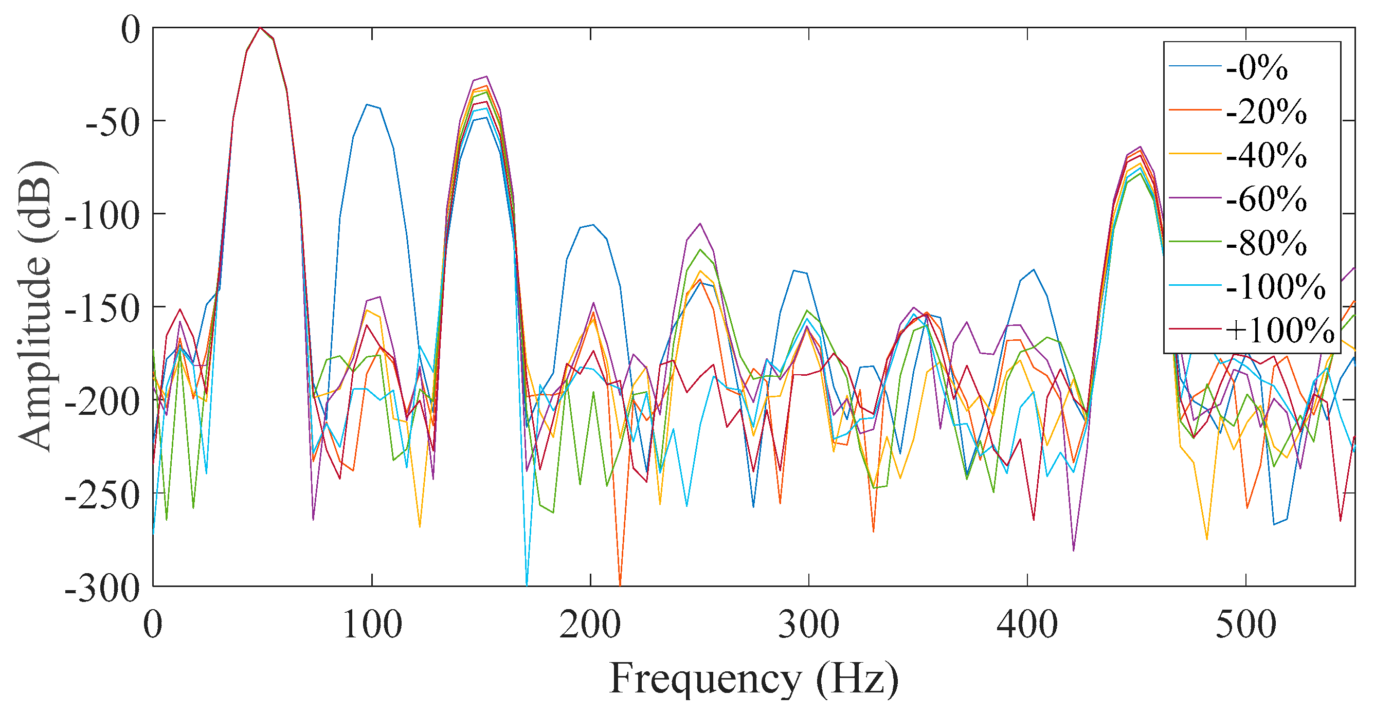
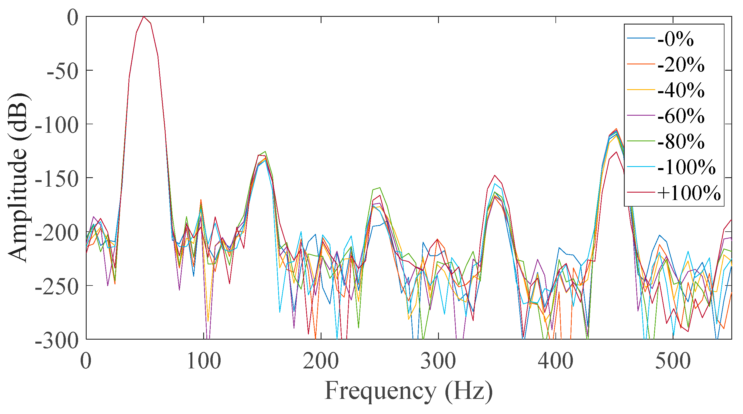
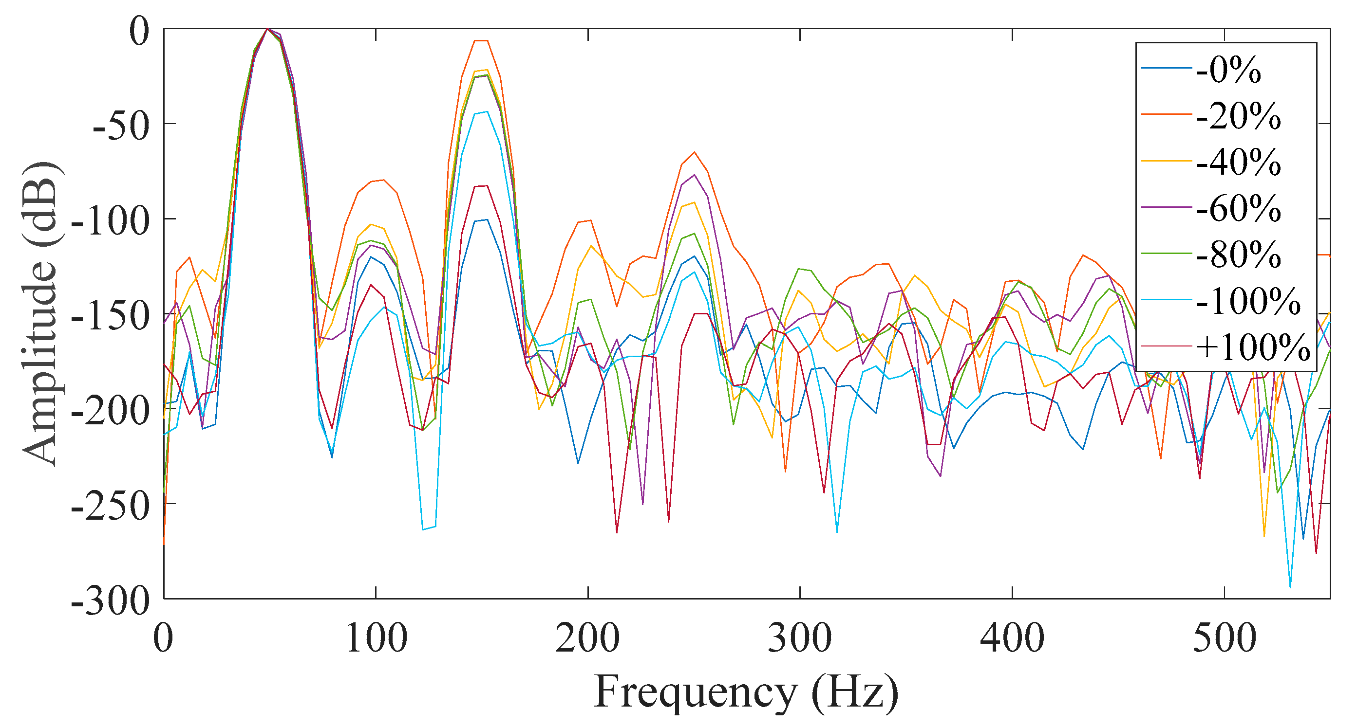
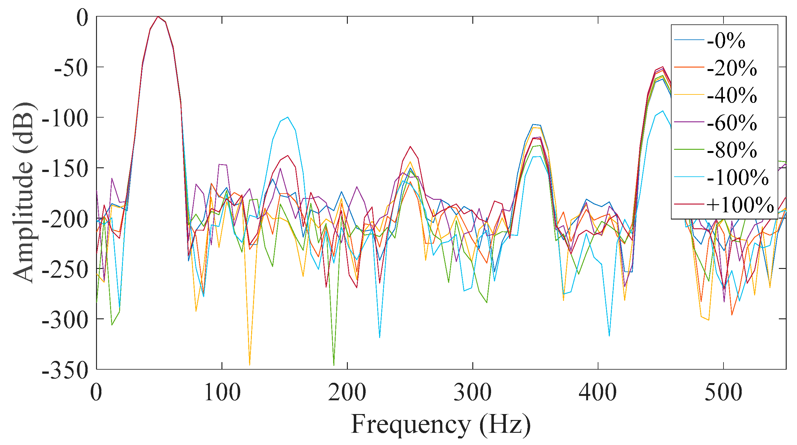
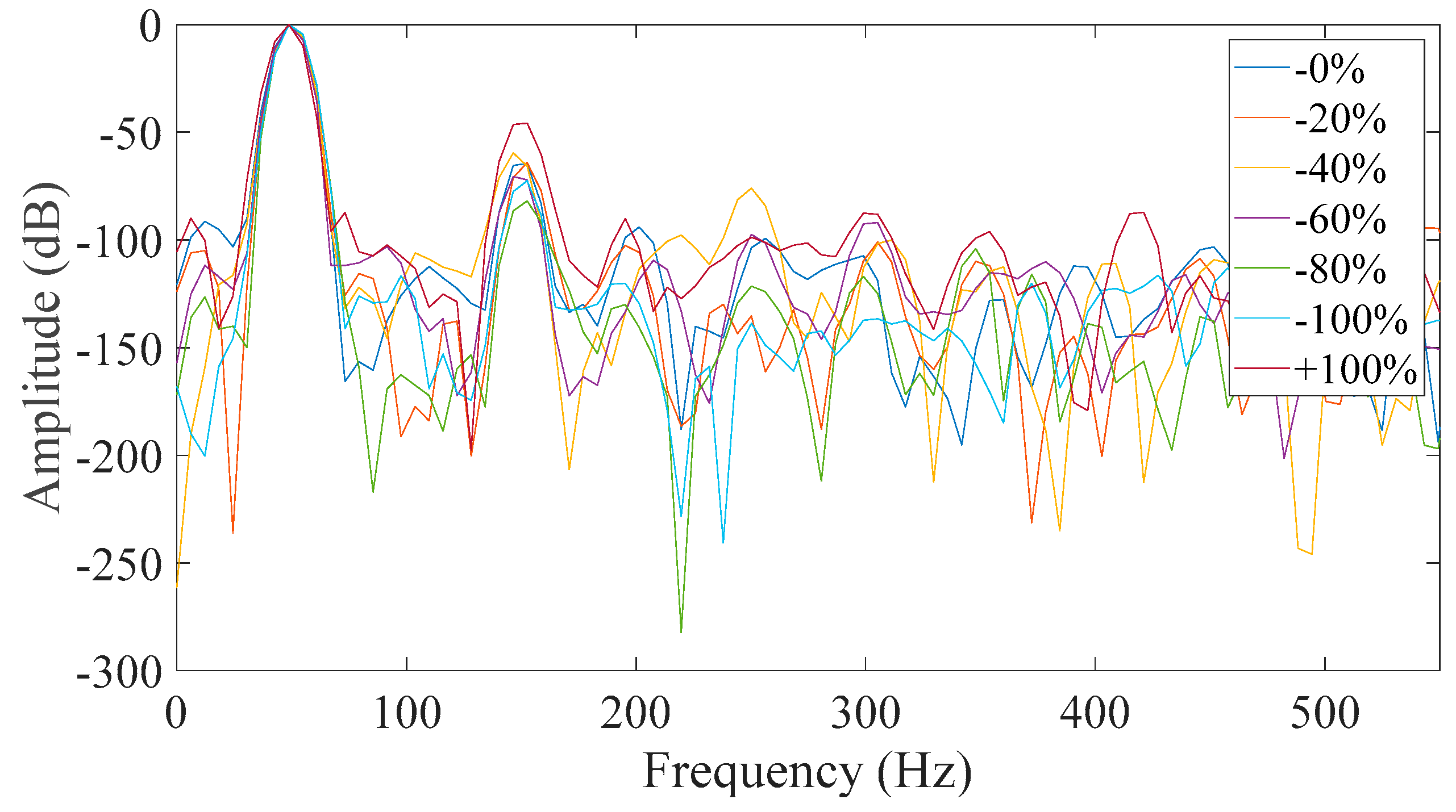
From all of the above shown possibilities, the most promising proved to be Case 3 (
Figure 11) and Case 7 (
Figure 15). The similarities between the two cases are that in both, the neutral was disconnected and the field winding was short-circuited. That is because all faulty cases appeared to have a significant increase of the third harmonic amplitude with respect to the healthy machine. However, it was observed that most of the captured data had a monotonic relation with the fault level severity in Case 7 which did not happen in Case 3. The monotony of the mechanism was not shown only for 80% severity, which is very close to 60% severity. That result could have been caused by many factors associated with inherent asymmetries during the testing and the fact that the test subject is a small machine with very short air-gap. So, the time when the rotor pole is across the measured phase was the best starting point in order to get reliable results.
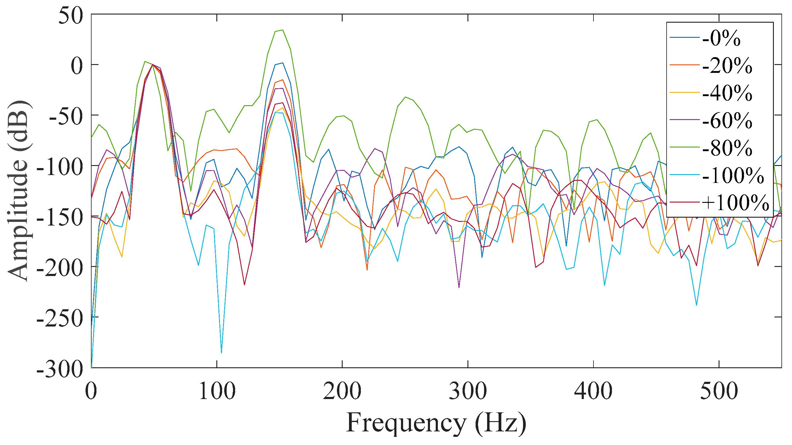
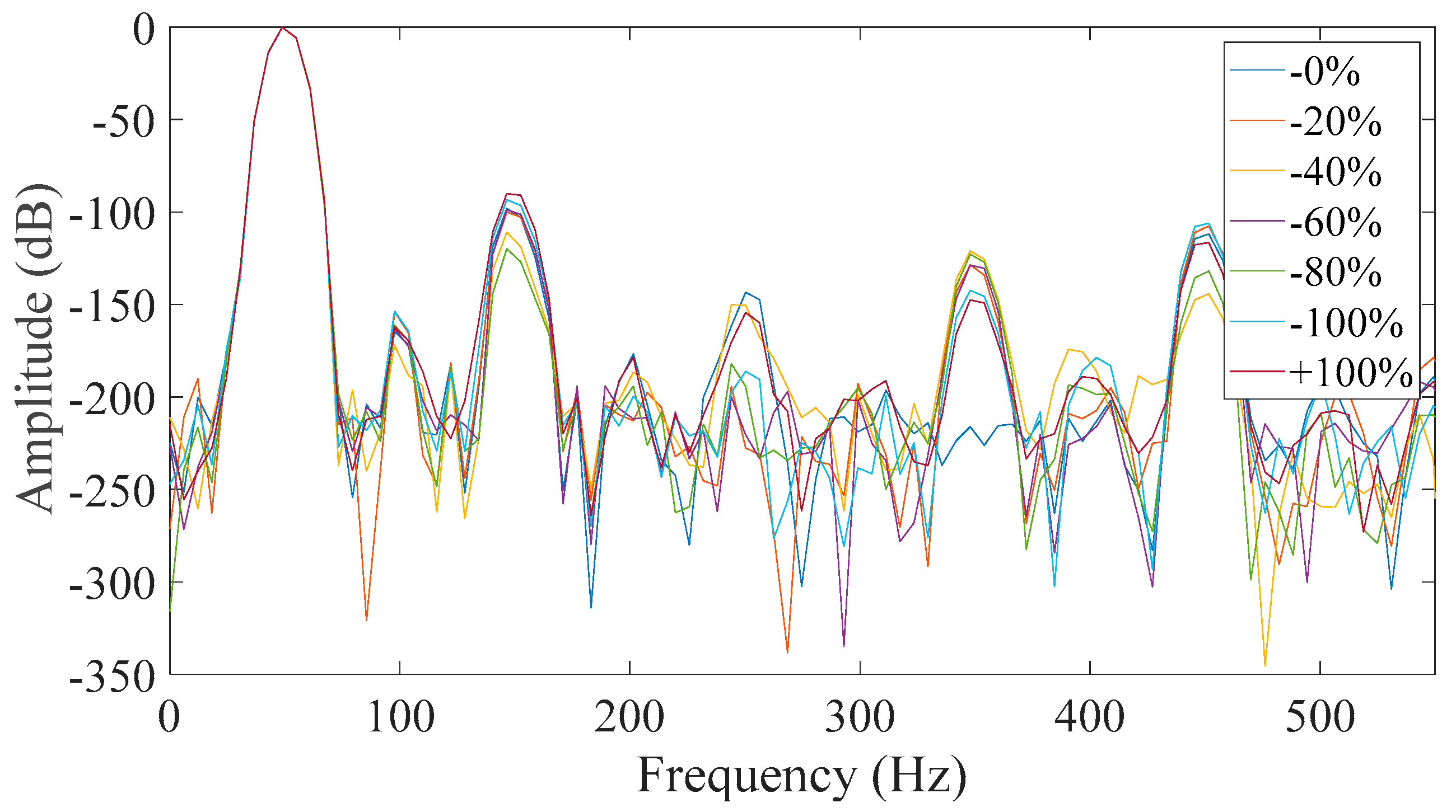
All other studied cases prove to be inadequate for reliable diagnosis where either the faulty cases are similar to the healthy ones, or the behavior of the third harmonic was not monotonic but random.
To summarize, the steps for the application of the proposed method used are the following:
Select the initial locked rotor position with respect to phase A, through monitoring of phase A current amplitude.
Supply the stator with a symmetrical 3-phase sinusoidal supply. Make sure that the voltage amplitude is at safe levels as the rotor is locked and no back-EMF exists.
Monitor Phase A current for the initial rotor position (IA R1).
Rotate the rotor mechanically by 120 degrees and monitor phase B current waveform (IB R21).
Rotate the rotor by another 120 degrees and monitor phase C current waveform (IC R3).
Sum the three currents leading to the calculation of the pseudo-zero-sequence current.
Apply the Fast Fourier Transform in the pseudo zero-sequence current and monitor the amplitude of the third harmonic.
5. The Impact of Saturation on the Applicability of the Method
This section will throw some light on the reason as to why the third harmonic amplitude of the pseudo-zero sequence current increased monotonically with the increase of the static eccentricity fault severity level. It is well known that the level of the iron core saturation is strongly dependent on the amplitude of the third current harmonic. So, an investigation to the behavior of the third harmonic under different rotor positions and for different fault level severities revealed the physical mechanism that leads to the proposed method’s reliability. It was shown recently that the Lissajous curve between the phase current and the zero-sequence current is saturation level dependent in induction motors [
25]. The method proposed in this paper is of the same philosophy as the one applied in induction machines if one considers that both machines are 3-phase and if the rotor winding of the synchronous machine is shorted, then it draws eddy currents from the rotating field in a similar way to the cage of the induction motor. However, the spatial distribution of the rotorfield is different due to the concentrated rotor winding and the rotor saliency, which is neglegible in induction motors due to the uniform air-gap.
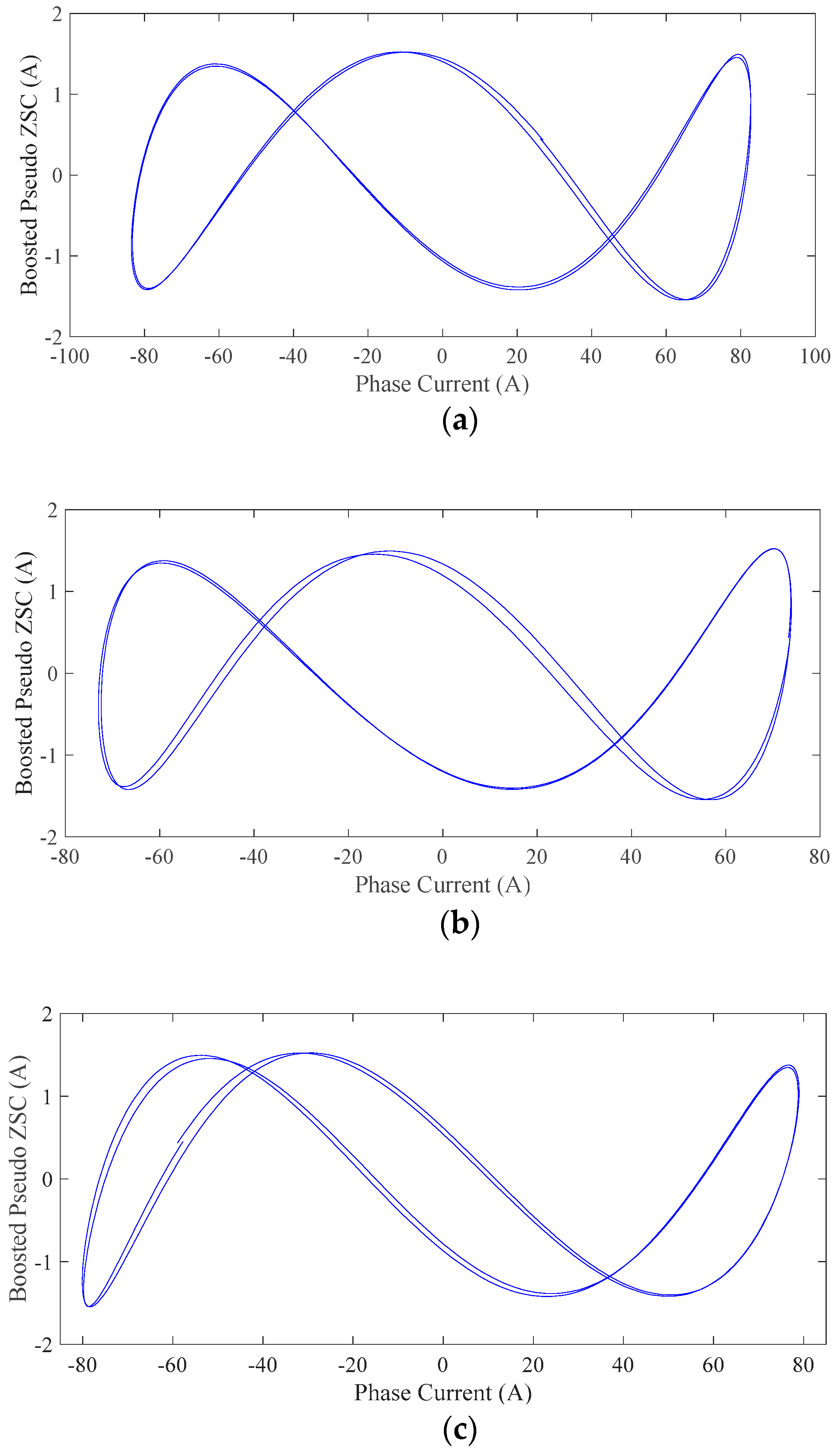
The waveform of the third harmonic alone was extracted from the pseudo zero-sequence current using appropriate filtering and then it was plotted against each phase current. This procedure was performed for the healthy case and for the machine with 80% eccentricity. The results are shown in
Figure 17 and
Figure 18 for the two above cases, respectively.
From
Figure 16 it can be seen that for the healthy machine case, all phases had phase difference between 0–45° with respect to the pseudo ZSC waveform. Theoretically they should be identical but the machine itself had some inherent asymmetries. Moreover, a small error might have been introduced during the experimental procedure, for example the initial rotor position was not exactly at the geometrical center of the stator.
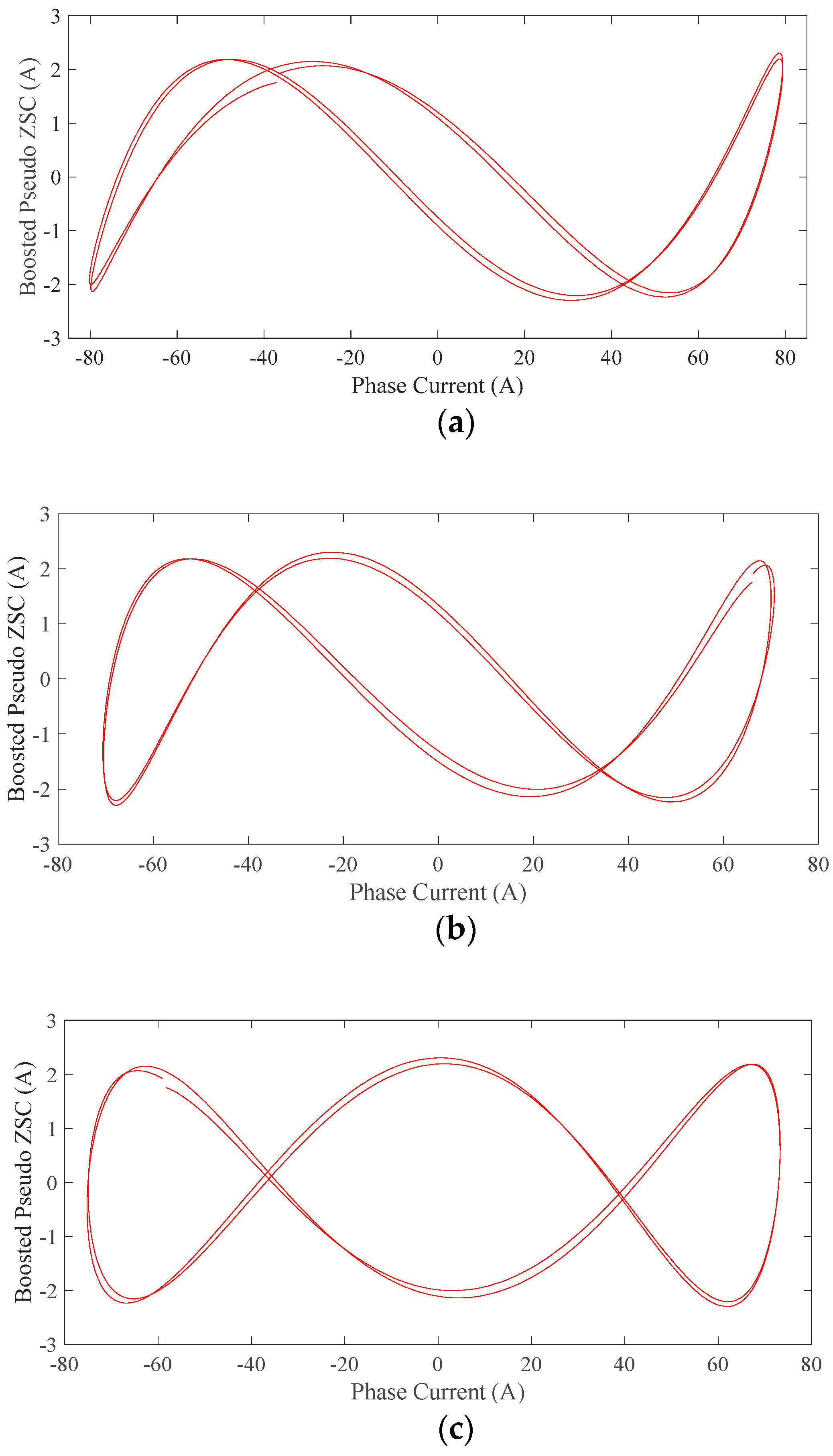
Despite the inherent asymmetry of the healthy machine,
Figure 18 reveals that the Lissajous curves of the first and second phase are similar to those of the healthy machine. However, the third phase’s Lissajous curve presented a significant phase shift of the pseudo ZSC. The two signals now appeared to have 90° phase difference. This phase shift is saturation related and was caused by the improper positioning of the rotor, as also shown earlier in
Figure 6.
6. Conclusions
This paper demonstrates a reliable method for the detection of static eccentricity in synchronous salient pole electric generators. The method relies on the calculation of a pseudo zero-sequence current obtained after monitoring the phase currents of the generator at standstill under three different rotor positions. The proposed method appears to be sensitive to the fault level severity, allowing for appropriate maintenance and service planning. It is to be noted that the method’s quantitative results depended on the non-linear characteristic of the iron core and the geometrical features of the machine, thus it is proposed to calibrate the method under healthy conditions in order to reliably detect the fault. That is because a small level of inherent eccentricity exists even in healthy machines due to manufacturing tolerances. Due to its effectiveness and simplicity, the method should be extended to cylindrical rotor synchronous machines, which is considered to be promising future work.


