1. Introduction
Due to fluctuations in the price of fossil fuels, the interest in renewable energy sources is increasing day by day [
1]. There are many methods of generating electricity from renewable sources, such as the wind turbine and solar panel. Wind turbines are among the most important of these methods. Wind turbines convert wind energy into electrical energy. Many types of generators are used in wind turbines [
2]. A permanent magnet synchronous generator (PMSG) has recently begun to attract the attention of wind turbine manufacturers, due to its superior features. The PMSG is supplied to the electrical grid system by means of the grid side converter (GSC), machine side converter (MSC), and control systems [
3,
4]. The fault ride-through (FRT) capability is one of the important issues for the operation system of the wind turbine. The grid connection requirements (GCRs) involve the operational condition control of the distributed power system [
5]. The GCRs have to provide efficiency and reliability to the electrical grid system. The wind turbine (WT) must remain connected to the electrical grid system during grid faults [
6]. The fault ride-through is depicted in three stages [
7]:
In the first stage, a WT supplies an electrical power grid system during grid fault time;
In the second stage, a wind turbine can inject reactive power to support the grid voltage recovery;
In the third stage, a WT restarts the delivery of the active power after a grid fault.
All these requirements must be considered in the design of the controller and power converter of the WT. This design increases the stability of the WT during a grid fault [
8]. Therefore, many methods are proposed in the literature for the FRT capability enhancement of the PMSG.
A braking chopper (BC) system has been implemented to enhance the FRT capability of a PMSG based on a wind energy conversion system (WECS) during a grid fault [
9,
10,
11,
12]. This method has some advantages, such as low cost and a simple control structure, but BC does not enhance the power quality in the WT’s output. The static synchronous compensator (STATCOM) has been implemented to analyze a dynamic mechanism for a wind farm [
13]. A coordinating control system for wind turbines was presented in Reference [
13]. However, STATCOM has disadvantages, such as high cost and additional hardware needs. The peak current limitation for a high-power PMSG was realized in Reference [
14]. Maximum power point tracking (MPPT) was implemented in the GSC and MSC. An active crowbar is kept the DC link voltage value by using this method. A superconducting fault current limiter (SFCL) was implemented for the FRT enhancement of a PMSG in Reference [
15]. The presented method achieved reductions in the fault currents in DC systems.
Recently, soft computing methods have started to develop rapidly with the development of computer technology. Soft computing methods are applied in real-world applications, such as renewable energy and automotive and motor control. Soft computing methods are widely implemented in wind power applications, such as for MPPT control, pitch control, fault diagnosis, wind power generation, wind turbine power control, and prediction of wind speed and power. Soft computing methods consist of four computing algorithms such as predictive method, genetic algorithm, artificial neural networks, and fuzzy logic controllers (Type 1 and Type 2).
Interval type-2 fuzzy logic control (IT-2 FLC) is a type of soft computing method that overcomes the uncertainties of any system [
16]. Uncertainty is a natural part of intelligent systems in many applications. Fuzzy Type 1 does not fully deal with the uncertainties of intelligent systems. An IT-2 FLC system is designed to minimize the uncertainties of any system. The IT-2 FLC system has been implemented in industrial applications. For example, interval type-2 hesitant fuzzy sets (IT2HFSs) have been implemented to cope with the underground hydrogen storage site selection problem in Romania [
17]. The IT-2 FLC system has been applied in wind power system applications, such as diagnosis, pattern recognition decision, classification, control, and time series prediction.
Mokryani et al. [
18] introduced a fault ride-through method using the FLC algorithm for several wind turbines. The presented method was applied to adjust the reactive and active power generated by the generator during grid faults. The proposed algorithm was utilized for all grid fault cases and different locations. Tahir et al. [
19] developed a low voltage ride-through (LVRT) method using an adaptive FLC algorithm for wind turbines based on a wound field synchronous generator (WFSG). The proposed method was applied to both power converters of a WT. The proposed control system improved the reactive power of the grid system and regulated the current of the grid side converter. Morshed and Fekih [
20] presented a design and analysis of the FRT method for a wind turbine. A new fuzzy second order integral terminal sliding mode control was developed for the power electronic converters. The proposed system was employed in a wind turbine. The overcurrents of the rotor and the stator with the presented control system did not exceed 10%. Therefore, the voltage and current values of the generator were within acceptable ranges. Rashid and Ali [
21] proposed to achieve an improved FRT capability based on a fuzzy logic controlled parallel resonance fault current limiter (FLC-PRFCL) for doubly fed induction generator (DFIG)-based wind farms. The effectiveness of the presented protecting control system was compared with conventional proportional-integral (PI) control, the bridge-type fault current limiter, and the crowbar circuit system. Bechkaoui et al. [
22] introduced online monitoring of grid faults based on the FLC method for wind plants. The proposed method provided a diagnosis of two grid faults. These faults were open phase and short-circuit. The proposed method was implemented to define the stator condition with high certainty. The data of the whole system were generated under both faulty and healthy conditions. The authors indicate that the proposed method is quite efficient. However, Fuzzy Type 1 does not fully cope with the uncertainties of complex systems, such as wind turbines. Several methods have been applied to deal with the uncertainties of complex systems in the literature [
23,
24,
25]. In addition, in the literature, the interval type-2 FLC has started to be implemented to cope with the uncertainties of complex systems.
Yassin et al. [
26] implemented a low voltage ride-through (LVRT) method using an interval type-2 FLC technique for a wind turbine. The input variables of the interval type-2 FLC technique were selected as the DC link voltage and rotor speed. There was irregularity between the delivered to the grid power and the generated active power. To protect from this harmful effect, the proposed method kept the DC link voltage constant. The authors indicate that the proposed algorithm is quite efficient. However, the interval type-2 FLC was implemented only to the MSC control during grid faults. In the normal operational condition, the system was controlled by a traditional control system (PI). The PI control system did not perform better than the IT-2 FLC in any aspect.
This paper proposes a new control approach using the IT-2 FLC method in the WT based on a PMSG to improve the transient stability during grid faults. An IT-2 FLC is designed to enhance the FRT performance of the PMSG. Unlike other studies in the literature, an IT-2 FLC was implemented to control the MSC and GSC of a PMSG during grid faults and normal operational conditions. The aim of the proposed control system is to maintain the generator connected with the grid system and to prevent the harmful effect of an overcurrent occurring during grid faults. The proposed IT-2 FLC is very simple, cost effective, and easy to implement in comparison to the conventional control system. All simulation results proved that the presented IT-2 FLC scheme has the capability to improve the FRT capability of a PMSG.
The rest of the paper is organized as follows: the wind energy conversion system is introduced in
Section 2, the proposed protection control system of a PMSG is presented in
Section 3, a review of the interval type-2 fuzzy logic system is given in
Section 4, the simulation results validating the proposed methodology are presented in
Section 5, and, finally, concluding remarks are provided in
Section 6.
2. Wind Energy Conversion System
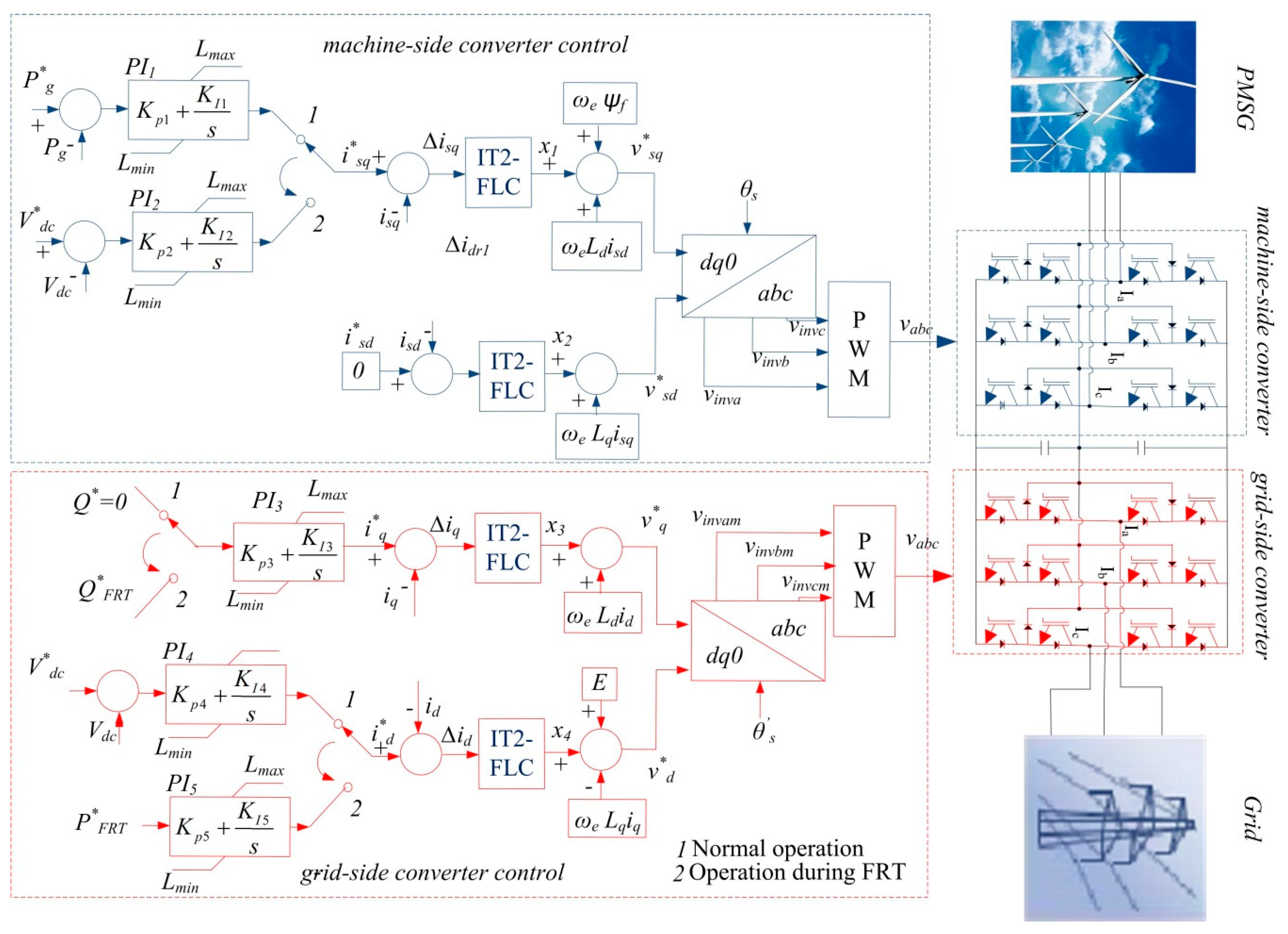
A WECS consists of a blade generator, control system, transformer, point of common coupling (PCC) system, and power electronics components, as shown in
Figure 1. Wind turbines convert wind energy into electrical energy. Many types of generators are used in wind turbines. Recently, PMSGs started being used in WTs. Both the GSC and MSC are required to connect wind turbines to the PCC. These converters consist of a neutral point clamped (NPC) system in the study. The NPC three-level converter systems are more effective than conventional converter methods for high-power applications.
2.1. Wind Turbine Characteristics
The mechanical power of the WT, which converts wind energy into electric energy, is calculated by the following formula [
27]:
where
Cp is the power coefficient and does not have a constant value. It varies with the tip speed ratio of the WT.
λ, which is the tip speed ratio of the WT, varies the rotational speed of the WT.
ρ, which is the air density, depends on both air pressure and temperature.
β denotes the pitch angle.
Vω depicts the wind speed.
A represents the area swept by a blade [
27].
λ is calculated by the formula
where
ωr depicts the rotor speed and
R depicts the blade radius.
The power coefficient (Cp), which is a function of the λ and β, is the most important parameter for the maximum power generated from a wind turbine. This parameter varies for each turbine type. The Cp value of each wind turbine is given as the table by the manufacturer. As shown in Equation (1), the maximum active power (Pm) changes linearly with the wind speed.
2.2. Mathematical Model of Permanent Magnet Synchronous Generator (PMSG)
The mathematical model of the PMSG is derived from the output voltage equations of the stator. The output voltage equations of the PMSG are illustrated in Equation (3) below. The windings are placed as balanced on the stator. The resistances of the windings are equal and depicted by
Rs =
Rq =
Rd.
Rs depicts the stator resistance,
Ls depicts the stator inductance, and
ωe denotes the electrical angular frequency.
vs, which depicts an output voltage of the PMSG, is described in Equation (3) [
27,
28,
29,
30]. The mathematical model is very useful for the generator to operate at optimum values and most important for the safe operation of the generator.
The stator flux linkages (
dq frame) are defined in Equation (4):
where
and
are the flux linkages,
Ld and
Lq represent the stator inductances in the
dq frame,
isd and
isq represent the generator’s
dq frame currents, and
represents the flux linkage in the permanent magnets. The
dq frame stator voltages by means of the flux linkages are as follows:
where
vsq and
vsd are the voltages of the
q and
d loops in the stator, respectively. The voltages of the
vsd and
vsq are utilized to generate the reference three-phase sinusoidal voltage, and the
isd and
isq depict the currents of the
d and
q loops in the stator, respectively.
Rs is a stator resistor,
Lq and
Ld represent the inductances of the
q and
d loops in the stator, respectively, and
ωe is the electrical angular of the PMSG.
3. Proposed Protection Control System
The controller design for the PMSG is very important in high performance applications. The design procedure for synthesizing and applying the controllers is very similar to the controllers in other high performance generators. However, the IT-2 FLC has more features than conventional control systems, such as numerical uncertainties and modeling the uncertainties in linguistic variables. The parameters of the PI are difficult to adjust for a WECS based on high nonlinearity with uncertain operating conditions. The PI controller supplies the proper performance for a given operating point. However, new methods have been investigated to overcome numerical uncertainties and new linguistics. The type-2 fuzzy set is a new method with specific characteristics. Thus, the special characteristics of the IT-2 FLC are used to improve wind energy conversion systems in this study. The block diagram for the IT-2 FLC is given in
Figure 1. An open source interval type-2 fuzzy logic system (IT2-FLS) Matlab/Simulink (R2106a, MathWorks, Natick, Massachusetts, USA) toolbox produced by Taskin and Kumbasar [
31] was used in this study.
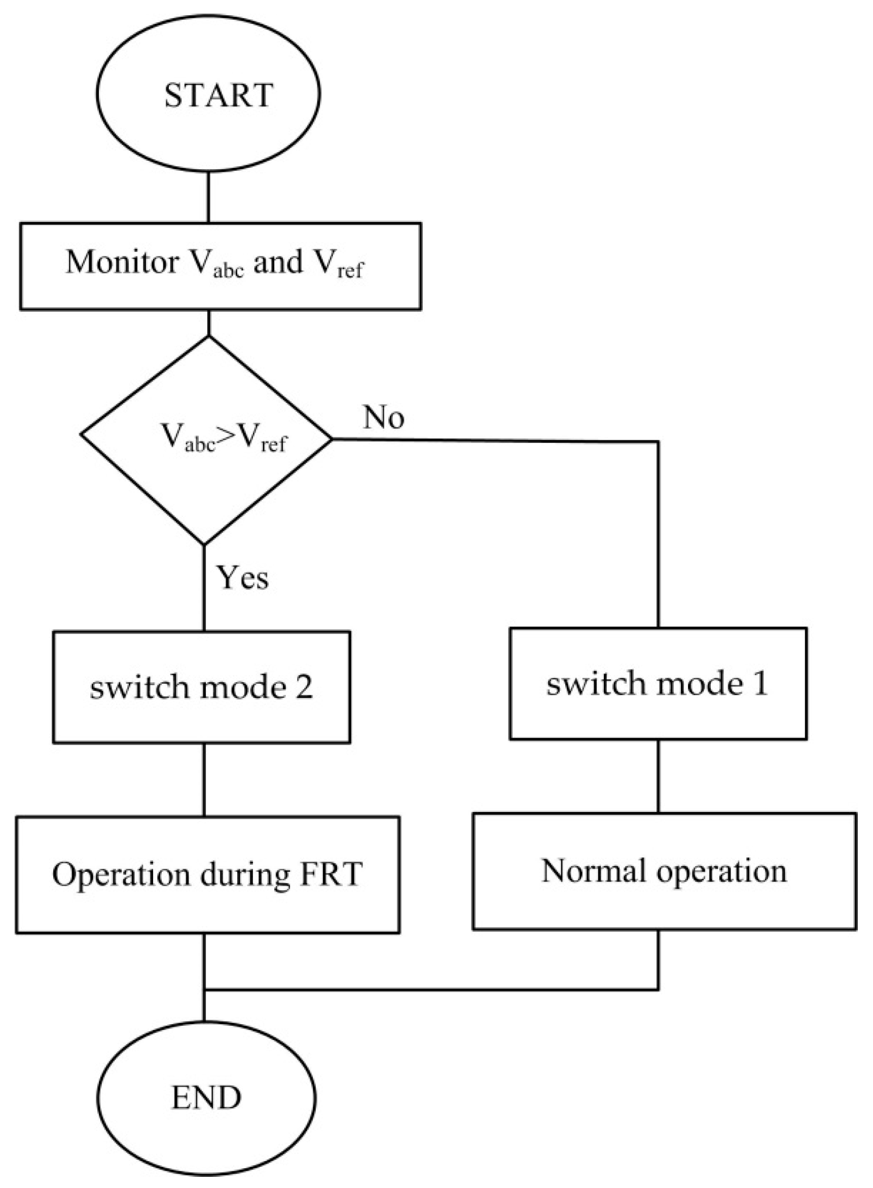
The line voltages are measured by the control system in the system runtime. The measurement voltages are compared with the reference voltage. When the measurement current value is higher than the reference current value, the switching mode is changed by the control system. A flowchart of the proposed control algorithm is given in
Figure 2.
The q loop of the machine side converter has two switching modes. The first mode is active during normal operation. The first mode input is the active power during normal operation. An error signal is produced by comparing the measured active power (P*g) with the reference active power (Pg). To obtain the reference current (i∗sq), this error signal is increased by the PI control.
The second mode is active during a grid fault. The input of the second mode is the DC link voltage. An error signal is produced by comparing the reference DC link voltage (Vdc) with the measured DC link voltage (V∗dc). To obtain the reference current (i∗sq), this error signal is increased by the PI control during a grid fault.
Δi∗sq is produced by comparing the reference current (i∗sq) with the measured current (isq). Δi∗sq is the input of the IT-2 FLC system for both the fault and normal operations. In this study, the IT-2 FLC was designed specifically to obtain efficient results in both the fault and normal operations. To obtain the required voltage (v*sq) for switching signals, the IT-2 FLC output signal (x1) sum with both ωeLdisd and ωeψf.
In addition, the d-axis current reference (i∗sd) of the MSC is set to 0. Δi∗sd is produced by comparing the reference current (i∗sd) with the measured current (isd). Δi∗sd is the input of the IT-2 FLC system for both the normal and fault operations. To obtain the required voltage (v*sd) for switching signals, the IT-2 FLC output signal (x2) is added to ωeLqisq.
In
Figure 1, the reference voltages (
v*sd and
v*sq) are added to enhance the transient response, as expressed by
The q loop of the grid side converter has two switching modes. The first mode is active during normal operation. The first mode input is the reactive power during normal operation. The reactive power (Q*) is set to 0. To obtain the reference current (i∗q), this error signal is increased by the PI control. The input of the second mode is the fault reactive power (Q*FRT). To obtain the reference current (i∗q), this error signal is increased by the PI control during a grid fault.
Δi∗q is obtained by comparing the reference current (i∗q) with the current measured (iq). Δi∗q is the input of the IT-2 FLC system for both the fault and normal operations. In this study, the IT-2 FLC was designed specifically to obtain efficient results in both fault operation and normal operation. To obtain the required voltage (v*q) for switching signals, the IT-2 FLC output signal (x3) is added to ωeLdid.
The second mode is active during the grid fault. The input of the second mode is the active power. To obtain the reference current (i∗d), this error signal is increased by the PI control.
Δi∗d is produced by comparing the reference current (i∗d) with the measured current (id). Δi∗d is the input of the IT-2 FLC system for both fault and normal operations. In this study, the IT-2 FLC was designed specifically to obtain efficient results in both the normal and fault operations. To obtain the required voltage (v*d) for the switching signals, the IT-2 FLC output signal (x4) is combined with both the ωeLqiq and E.
In
Figure 1, the reference voltages (
v*d and
v*q) are added to enhance the transient response, expressed as
4. Overview of Interval Type-2 Fuzzy Logic Systems
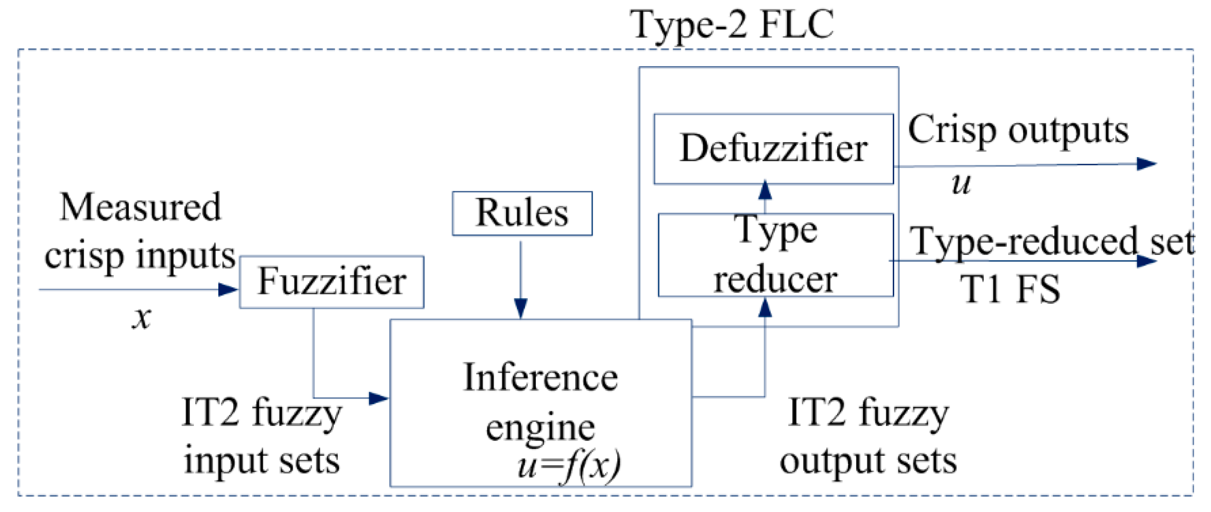
The first interval type-2 method was proposed by Zadeh in 1975. Then, many other authors started to implement the IT-2 FLC system in many applications. The IT-2 FLC method consists of five components: fuzzifier, rules, inference engine, type reducer, and defuzzifier. The structure of the IT-2 FLC method is given in
Figure 3. The crisp inputs of the IT-2 FLC are obtained from the input sensors. The fuzzifier converts the physical input values into a normalized fuzzy subset. The inference engine of the IT-2 FLC system uses the same rules as those used in a T-1 FLC system. Then, the type reducer converts the IT-2 FLC to a T-1 FLC. Finally, defuzzification is usually called output processing [
32]. The fuzzifier is the first stage in applying fuzzy logic control. The fuzzifier converts the physical input values into a normalized fuzzy subset. The physical input values of the sensors are mapped to a set of input fuzzy values [0, 1] by the membership functions. Finally, the fuzzifier converts the physical input values to a fuzzy input of the inference engine [
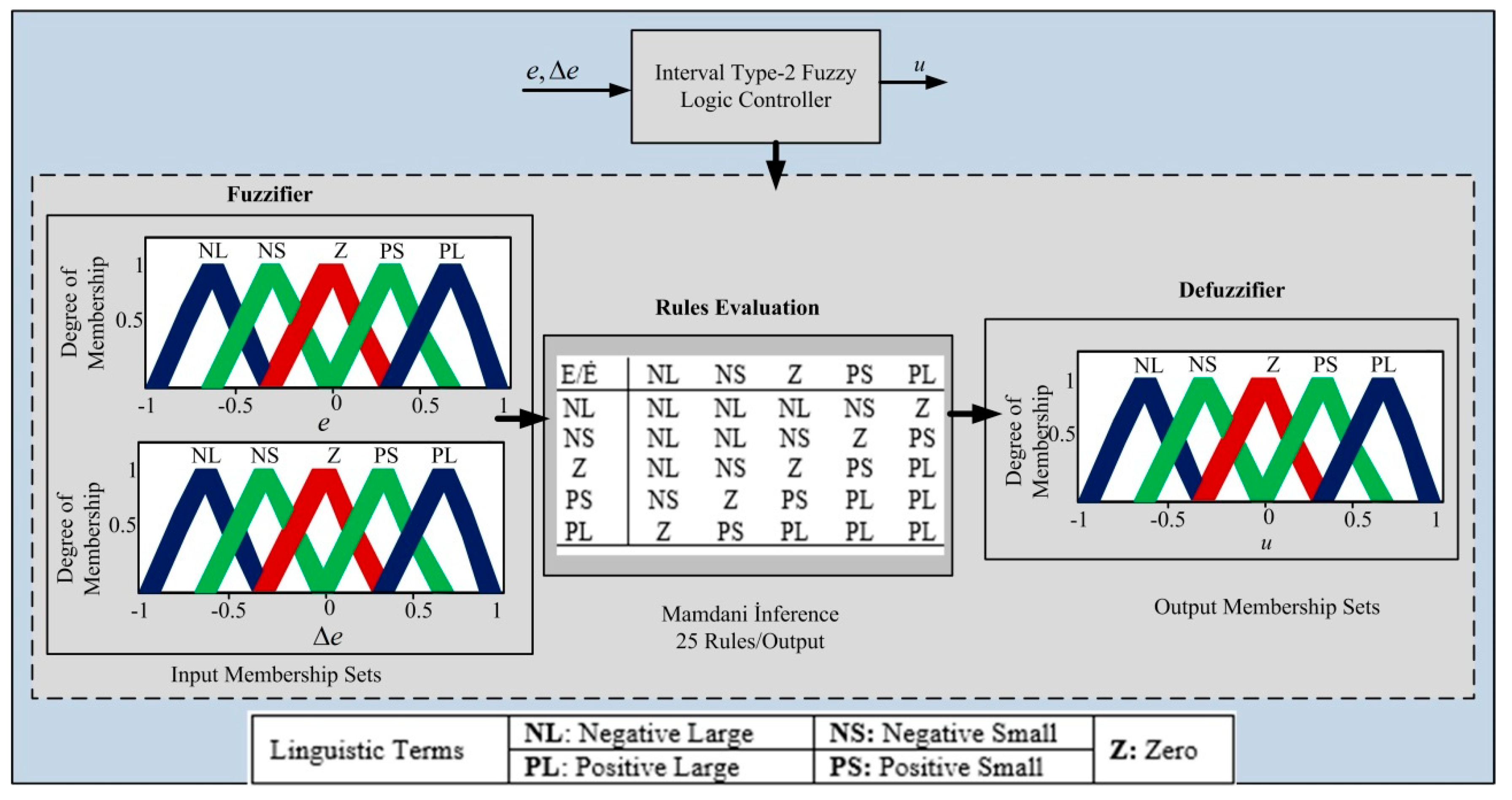
33]. The general membership functions of the IT-2 FLC are given in
Figure 4.
The inference engine is the second stage in applying fuzzy logic control. The inference engine is regarded as a transformer, which from a given input maps an output by using linguistic variables. The inference engine generates functional mapping between the output and the input using fuzzy mapping rules. The inputs of the inference engine are implemented by a set of fuzzy mapping rules (if/then). The fuzzy mapping rules (if/then) decide a given condition using linguistic variables, and, then, the fuzzy sets convert to a set of fuzzy outputs [
34,
35]. All 25 rules and membership functions for the IT-2 FLC are selected and given in
Figure 4. Fuzzy rules are written as follows: if (input1 is membership function1) and/or then (output is output membership function).
Mamdani systems have widespread acceptance, are well suited to human input, and are intuitive. Therefore, the Mamdani system was used in this study.
The defuzzifier is the third stage in applying fuzzy logic control. The defuzzifier converts the fuzzy output available into the control objective. The output of the inference engine is still a linguistic variable. This linguistic variable is transformed into the crisp output by the defuzzifier stage. This stage is regarded as a conversion from the fuzzy output to the crisp output needed for real applications. The mean of the maximum technique, a center of gravity technique, and height techniques are commonly used in defuzzification. The Karnik–Mendel algorithm was implemented in this study as the defuzzification method. The Karnik–Mendel algorithm identifies the largest and smallest elements among the centroids [
36]. This method converts fuzzy values into crisp system output values, expressed as
5. Simulation Results
The simulations in this study were realized in Matlab/Simulink to verify the effectiveness and analysis of the presented method. The sampling frequency of the presented Simulink system was modeled at 20 kHz. The parameters of the PMSG, turbine, and power converter systems are given in
Table A1,
Table A2 and
Table A3, respectively. An open source IT2-FLC toolbox in Matlab/Simulink was used in this study. The rules of the IT-2 FLC system were designed to maximize the power generation from the generator. The IT-2 FLC rules were adjusted to generate the optimized gains for the power performance of the wind system based on the PMSG. An IT-2 FLC control system was implemented for the analysis of three different cases of grid fault. The different types of symmetrical and asymmetrical faults were implemented separately at the proper time on the grid side of the PMSG. The simulated fault conditions were as follows:
(i) The 3/ϕ symmetrical fault was implemented at t = 4.0 s and was cleared at t = 4.5 s;
(ii) The 2/ϕ asymmetrical fault was implemented at t = 4.0 s and was cleared at t = 4.5 s;
(iii) The 1/ϕ asymmetrical fault was implemented at t = 4.0 s and was cleared at t = 4.5 s.
The generator with the proposed control method was connected to the grid during all grid fault types. The simulation results illustrate that the IT-2 FLC system gives an appropriate performance for the power generation of the wind system using a PMSG for different scenarios. The rated value of the DC link was 1150 V, the rated value of active power was 1 p.u., the rated value of the electromagnetic torque power was 1 p.u., and the rated value of the reactive power was 0 p.u. in the study.
Scenario 1
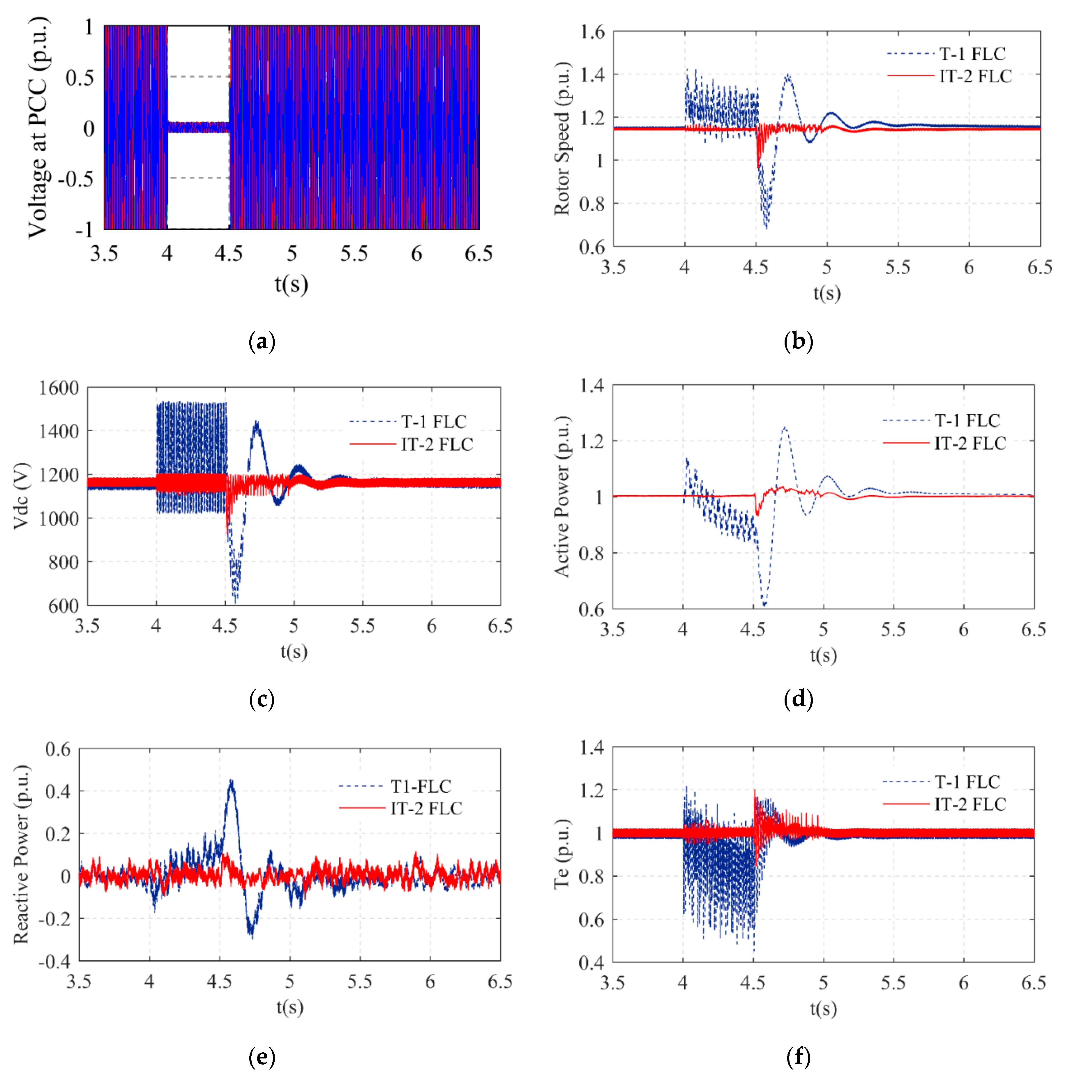
The 3/
ϕ symmetrical fault was implemented at t = 4.0 s, and then it was cleared at t = 4.5 s, as shown in
Figure 5a. The 3/
ϕ symmetrical fault was the severest fault type used. Therefore, the control of this fault type is vital. The IT-2 FLC and T-1 FLC were separately implemented in the WT. The parameters of the WT that were measured were the rotor speed, DC link (Vdc), electromagnetic torque (Te), and reactive and active power. The maximum value of the rotor speed with the T-1 FLC system was 1.4 p.u., and its drop value was 70% p.u., as shown in
Figure 5b. However, the maximum value of the rotor speed with the IT-2 FLC system was near the nominal value, and the drop value of the rotor speed was 1 p.u., as shown in
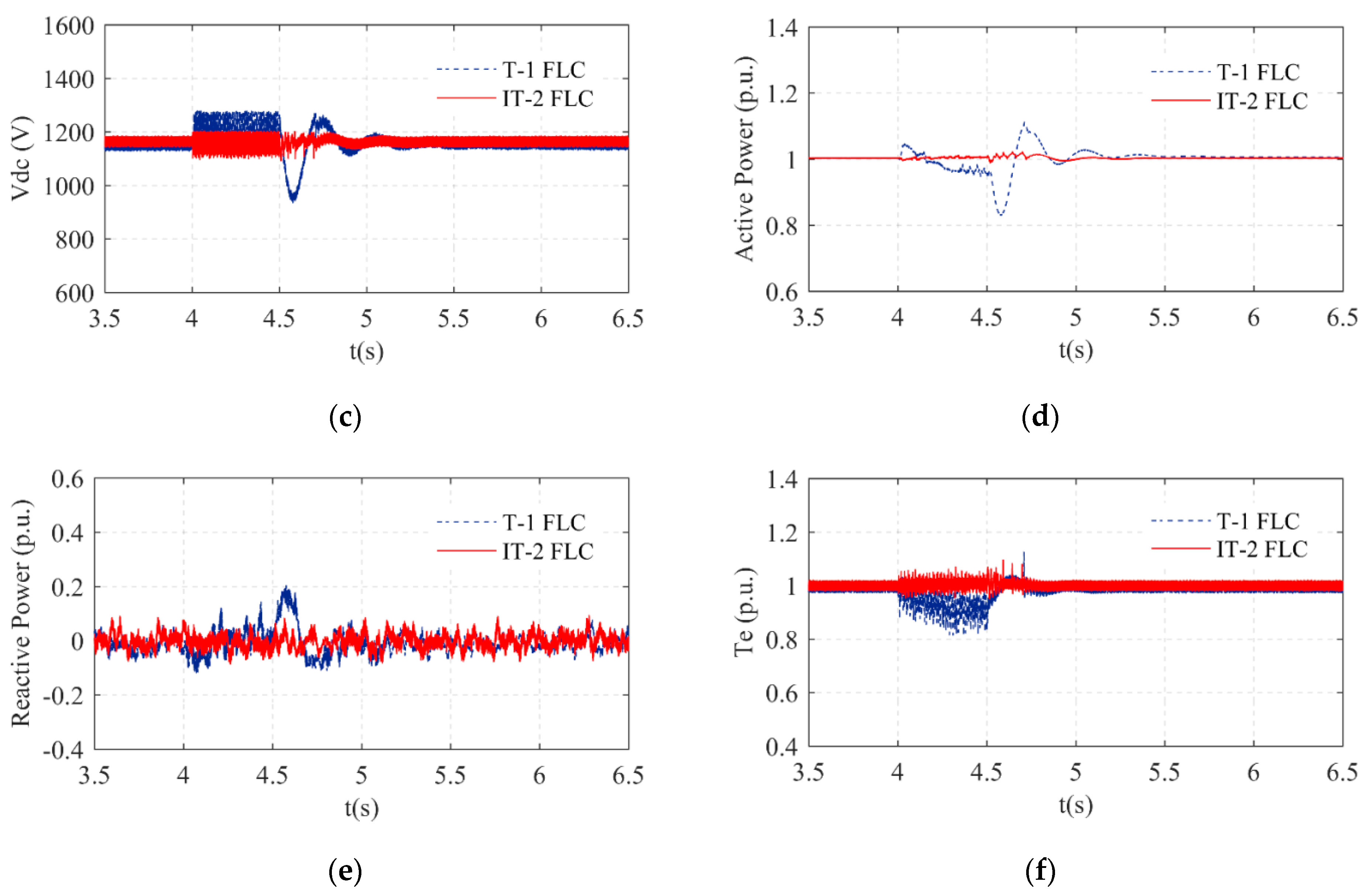
Figure 5b. The DC link voltage of the system is given in
Figure 5c. The DC link voltage value using a T-1 FLC system was 1400 V during the grid fault, while the DC link voltage value with the IT-2 FLC system was near the nominal value. The oscillation of the DC link voltage value with the T-1 FLC system was higher than the proposed control system even after the grid fault time. The active power of the system is given in
Figure 5d. The drop value of the active power with the T-1 FLC was 60% p.u. and the overshoot value of the active power with the T-1 FLC was 1.25 p.u. However, the active power value with the IT-2 FLC was near the nominal value. The reactive power of the system is given in
Figure 5e. The overshoot value of the reactive power with the T-1 FLC system was 40% p.u. The ripple of the reactive power value with the proposed control system was smaller than the T-1 FLC system. The reactive power value of the IT-2 FLC system was the nominal value both during and after the grid fault. The electromagnetic torque (Te) of the system is given in
Figure 5f.
The ripple of the electromagnetic torque value with the proposed control system was smaller than the T-1 FLC system. The electromagnetic torque value with the IT-2 FLC system was the nominal value both during and after the grid fault.
Scenario 2
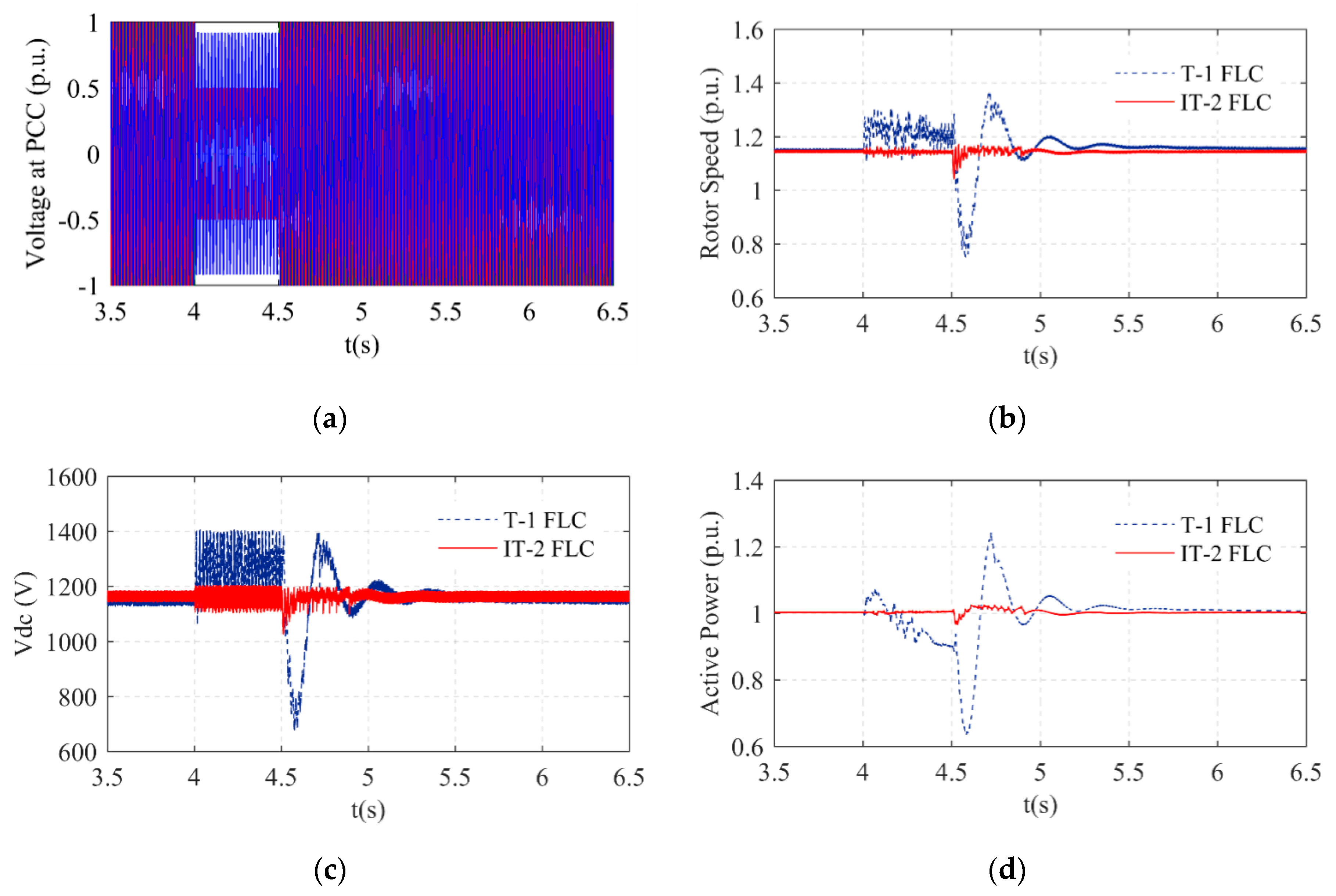
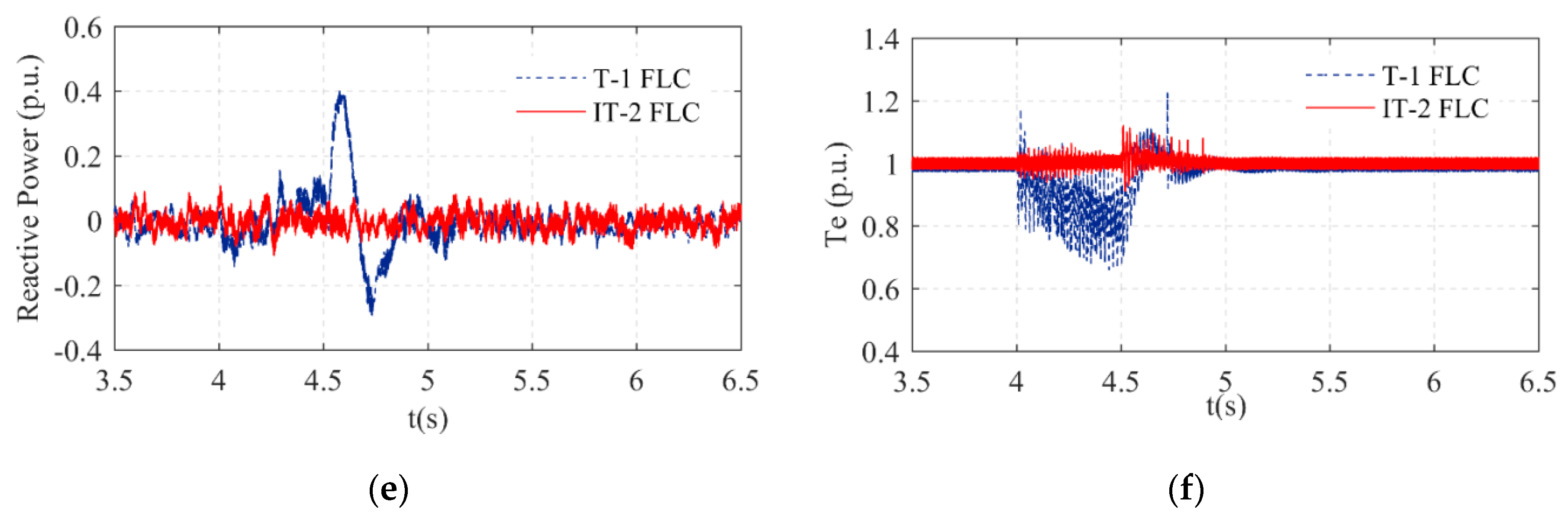
The 2/
ϕ asymmetrical fault was implemented at t = 4.0 s, and then it was cleared at t = 4.5 s, as shown in
Figure 6a. The 2/
ϕ asymmetrical fault was lighter compared to the 3/
ϕ symmetrical fault. However, the 2/
ϕ asymmetrical fault was more severe than the 1/
ϕ asymmetrical fault. The IT-2 FLC and T-1 FLC were separately implemented in the system during the 2/
ϕ asymmetrical fault, as shown in
Figure 6a. The rotor speed, DC link (
Vdc), electromagnetic torque (
Te), and the reactive and active power of the system with the IT-2 FLC had near nominal values and are given in
Figure 6b–f, respectively. The rotor speed value with the T-1 FLC system increased to 1.4 p.u. in
Figure 6b. The overshoot value of the DC link with the T-1 FLC system was 1400 V. The ripples in the DC link voltage value with the T-1 FLC system were higher than the proposed control system even after the grid fault time. The drop value of the active power with the T-1 FLC was 63% p.u., and the overshoot value of the active power with the T-1 FLC was 1.21 p.u. The ripple in the active power was greatly reduced by the IT-2 FLC. The reactive power with the T-1 FLC did not track the ideal zero value during the grid fault. The reactive power value with the T-1 FLC was 40% p.u. during the grid fault. The reactive power value with the proposed control system matched the ideal value perfectly both during and after the grid fault. The ripple of the electromagnetic torque value with the proposed control system was smaller than with the T-1 FLC system.
The electromagnetic torque value with the IT-2 FLC system was the nominal value both during and after the grid fault.
Scenario 3
The 1/
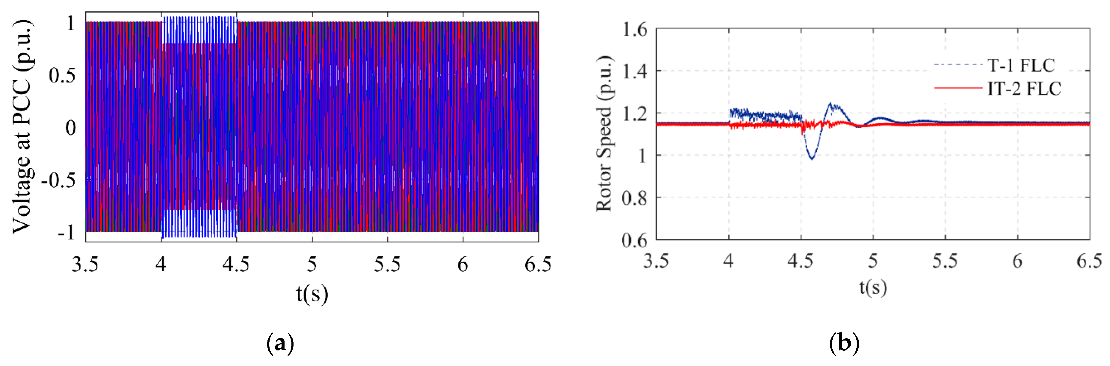
ϕ asymmetrical fault was implemented at t = 4.0 s, and then it was cleared at t = 4.5 s, as shown in
Figure 7a. The 1/
ϕ asymmetrical fault was lighter than the other fault types. However, the 1/
ϕ asymmetrical fault is the most common type of grid fault. Therefore, the control of this fault type is vital. The IT-2 FLC and T-1 FLC were separately implemented in the system. The parameters of the system that were measured were the rotor speed, DC link (Vdc), electromagnetic torque (Te), and reactive and active power. The maximum value of the rotor speed with the T-1 FLC system was 1.2 p.u., and its drop value was 1 p.u. value, as shown in
Figure 7b. The DC link voltage with the T-1 FLC system was 1300 V during the grid fault. The drop value of the active power with the T-1 FLC was 82% p.u., and the overshoot value of the active power with the T-1 FLC was 1.05 p.u. The parameters of the system that were observed were the rotor speed, DC link (
Vdc), electromagnetic torque (
Te), and reactive and active power. The rotor speed, DC link (
Vdc), active power, reactive power, and electromagnetic torque (
Te) of the system with the IT-2 FLC had near nominal values and are given in
Figure 7b–f, respectively. All the parameters of the system with the IT-2 FLC closely tracked the rated values both during and after the grid fault.
All the parameters with the proposed control system settled to the rated value within comparatively less time than with the T-1 FLC system. The proposed control system reduced the ripples of all the parameters in the system due to the appropriate selection of IT-2 FLC parameters.
6. Conclusions
The FRT capability of wind turbines is a vital issue for the electrical energy generated from wind energy and contributes to reliable grid integration. This paper proposes a new control approach using the IT-2 FLC method that is implemented in the WT based on a PMSG to improve the transient stability during grid faults. The main contributions of this work are:
- (i)
An IT-2 FLC was designed to enhance the fault ride-through performance of the PMSG in order to obtain effective results during grid faults;
- (ii)
The proposed control system was applied to control the MSC and GSC of the PMSG;
- (iii)
It was observed by measurements that the proposed control system protects the power electronic devices from the harmful effect of overvoltage during grid faults;
- (iv)
The simulation results have confirmed that the proposed control system can effectively reduce the ripples of all the parameters in the system. The proposed system also improved the conversion efficiency of the wind turbine system due to the appropriate selection of IT-2 FLC parameters.
The parameters of the system that were observed were the rotor speed, DC link (Vdc), electromagnetic torque (Te), and reactive and active power. The rotor speed, DC link (Vdc), active power, reactive power, and electromagnetic torque (Te) of the system with the IT-2 FLC had near nominal values. All the parameters of the system with the IT-2 FLC system closely tracked the rated values during and after the grid faults. All the parameters with the proposed control system settled to the rated value within comparatively less time than the T-1 FLC system. All the simulation results proved that the presented IT-2 FLC scheme has the capability to improve the FRT capability of the PMSG and performs better than the T-1 FLC in all aspects.
In the future, the other rule evaluation method (Sugeno) should be applied to the system. In addition, different interval type-2 fuzzy logic control systems, such as the IT-2 FLC PI, can be adapted to improve the FRT performance of wind turbines, and the results can be compared with the results in this paper.

