Article

Optimization of the Fuel Cell Renewable Hybrid Power System Using the Control Mode of the Required Load Power on the DC Bus

by
Nicu Bizon
1,2,*,
Valentin Alexandru Stan
2 and
Angel Ciprian Cormos
2
1
Faculty of Electronics, Communication and Computers, University of Pitesti, 1 Targu din Vale, 110040 Pitesti, Romania
2
Polytechnic University of Bucharest, 313 Splaiul Independentei, 060042 Bucharest, Romania
*
Author to whom correspondence should be addressed.
Energies 2019, 12(10), 1889; https://doi.org/10.3390/en12101889
Submission received: 9 March 2019 / Revised: 19 April 2019 / Accepted: 14 May 2019 / Published: 17 May 2019
(This article belongs to the Special Issue Fuel Cell Renewable Hybrid Power Systems)

Abstract

:
In this paper, a systematic analysis of seven control topologies is performed, based on three possible control variables of the power generated by the Fuel Cell (FC) system: the reference input of the controller for the FC boost converter, and the two reference inputs used by the air regulator and the fuel regulator. The FC system will generate power based on the Required-Power-Following (RPF) control mode in order to ensure the load demand, operating as the main energy source in an FC hybrid power system. The FC system will operate as a backup energy source in an FC renewable Hybrid Power System (by ensuring the lack of power on the DC bus, which is given by the load power minus the renewable power). Thus, power requested from the batteries’ stack will be almost zero during operation of the FC hybrid power system based on RPF-control mode. If the FC hybrid power system operates with a variable load demand, then the lack or excess of power on the DC bus will be dynamically ensured by the hybrid battery/ultracapacitor energy storage system for a safe transition of the FC system under the RPF-control mode. The RPF-control mode will ensure a fair comparison of the seven control topologies based on the same optimization function to improve the fuel savings. The main objective of this paper is to compare the fuel economy obtained by using each strategy under different load cycles in order to identify which is the best strategy operating across entire loading or the best switching strategy using two strategies: one strategy for high load and the other on the rest of the load range. Based on the preliminary results, the fuel consumption using these best strategies can be reduced by more than 15%, compared to commercial strategies.

1. Introduction

The very fast increase of global energy demand over recent decades calls for a new approach to energy sustainable development based on Hybrid Power Systems (HPS) combining Renewable Energy Sources (RESs) and Fuel Cell (FC) systems [1,2,3]. Therefore, innovative solutions based on experimental research have been proposed for the implementation of the Fuel Cell Hybrid Power Systems (FCHPS) with or without support from the RESs [4,5,6].
The state-of-the-art studies in this field have identified the following challenging topics for the next stage of research [7,8,9]:
  • Modeling, control, and optimization of the FC system to improve the fuel economy [10,11,12];
  • Developing innovative solutions and advanced technologies to improve the lifetime, reliability and safety in operation of the FC system [13,14];
  • Numerical models for the control of hydrogen and thermal/electric energies productions through Solid Oxide Electrolyzer/Fuel Cells [15]:
  • Proposal of innovative stand-alone or grid-connected RES HPS architectures, which can be optimized based on advanced Energy Management Strategies (EMSs) [16,17,18] and Global Maximum Power Point Tracking (GMPPT) control algorithms [19,20,21] applied to available RESs (photovoltaic systems, wind turbines etc.) in order to optimally ensure the power flow balance on the DC bus (and/or the AC bus) [22,23,24] and improve the harvested energy from the RESs [25,26,27];
  • Hybridization of the RES HPS with an FC system as backup energy source (FC/RES HPS) to mitigate the RES power variability and load dynamics by controlling the generated FC power at the level of the required power on the DC bus [28,29,30].
  • Use of hybrid Energy Storage Systems (ESSs) with advanced control of the ESS bidirectional power converters to ensure that the DC voltage regulation and mitigation of the power pulses on the DC bus as well [31,32,33];
  • Improving the fuel economy of the FC vehicles (FCVs) by using innovative FCV powertrain [34,35,36], advanced EMSs [37,38,39], and hybrid technologies [40,41,42];
  • Optimal sizing of the FC RES HPSs [43,44,45], FCVs [46,47,48], and hybrid ESSs [49,50].
  • Electrical and thermal analysis of the HPS [51].
In this study, the optimization of the FCHPS is approached using the control mode of the required load power on the DC bus, named the Required-Power-Following (RPF) control-mode of the FC system. The FC system using RPF-control mode will generate, on the DC bus, the needed power to compensate the DC power flow balance for a Hybrid Power System operating with a variable load demand. The RPF-control mode will use one from the three inputs variables of the FC system that can control the FC power: the reference input for the FC boost controller, the air regulator, or the fuel regulator. So, the other two inputs or only one input can be used to optimize the operation of the FC system in order to improve the fuel consumption based on the optimization function chosen. Thus, the RPF-control loop and two optimization loops controlling all three reference inputs of the FC system means three optimization strategies. In addition, beside one needed loop for the RPF-control, only one optimization loop controlling two from the three reference inputs of the FC system means the other four optimization strategies. Consequently, seven optimization strategies can be set for an FC Hybrid Power System to be analyzed.
The real-time searching and tracking of the optimum is mandatory for the optimization algorithm used in this study [52,53,54]. Furthermore, the optimization function is time-dependent and could become a multimodal type by controlling the FCHPS in different operating modes [55]. So, a Real-Time Optimization (RTO) algorithm must be selected to search the global optimum. The Global Extremum Seeking (GES) scheme proposed in [20] will be considered here, with minor changes of the parameters’ values to improve the searching performance.
Summarizing, the novelty of this study is that seven RTO strategies will be analyzed for a FCHPS under the same load profile in order to estimate the fuel consumption compared to that obtained using the Static Feed-Forward (sFF) strategy, which is commercially implemented [56].
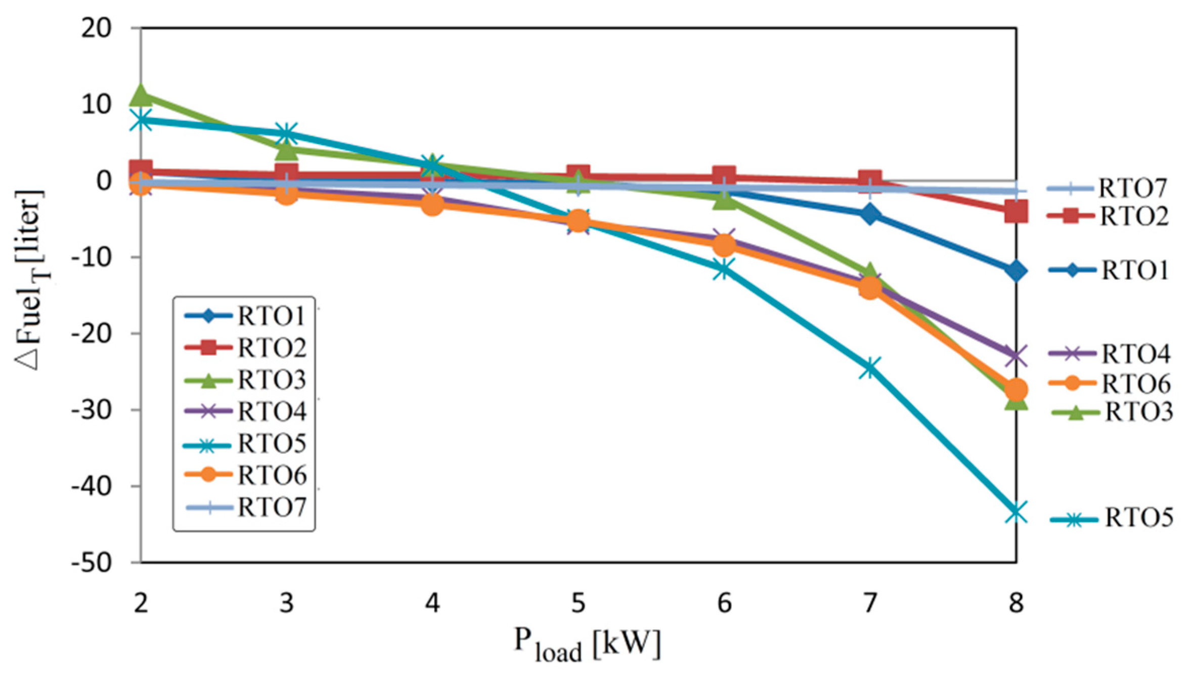
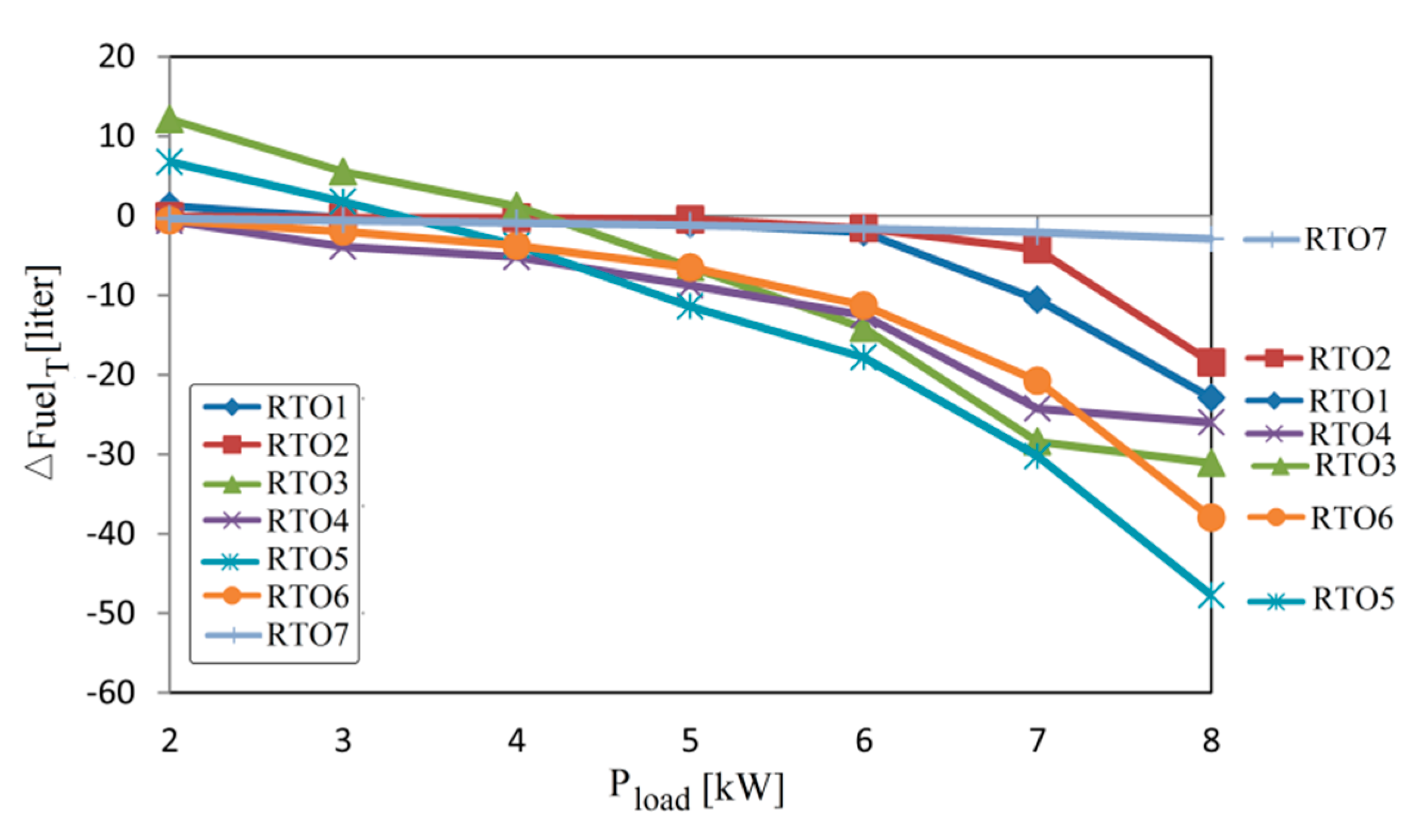
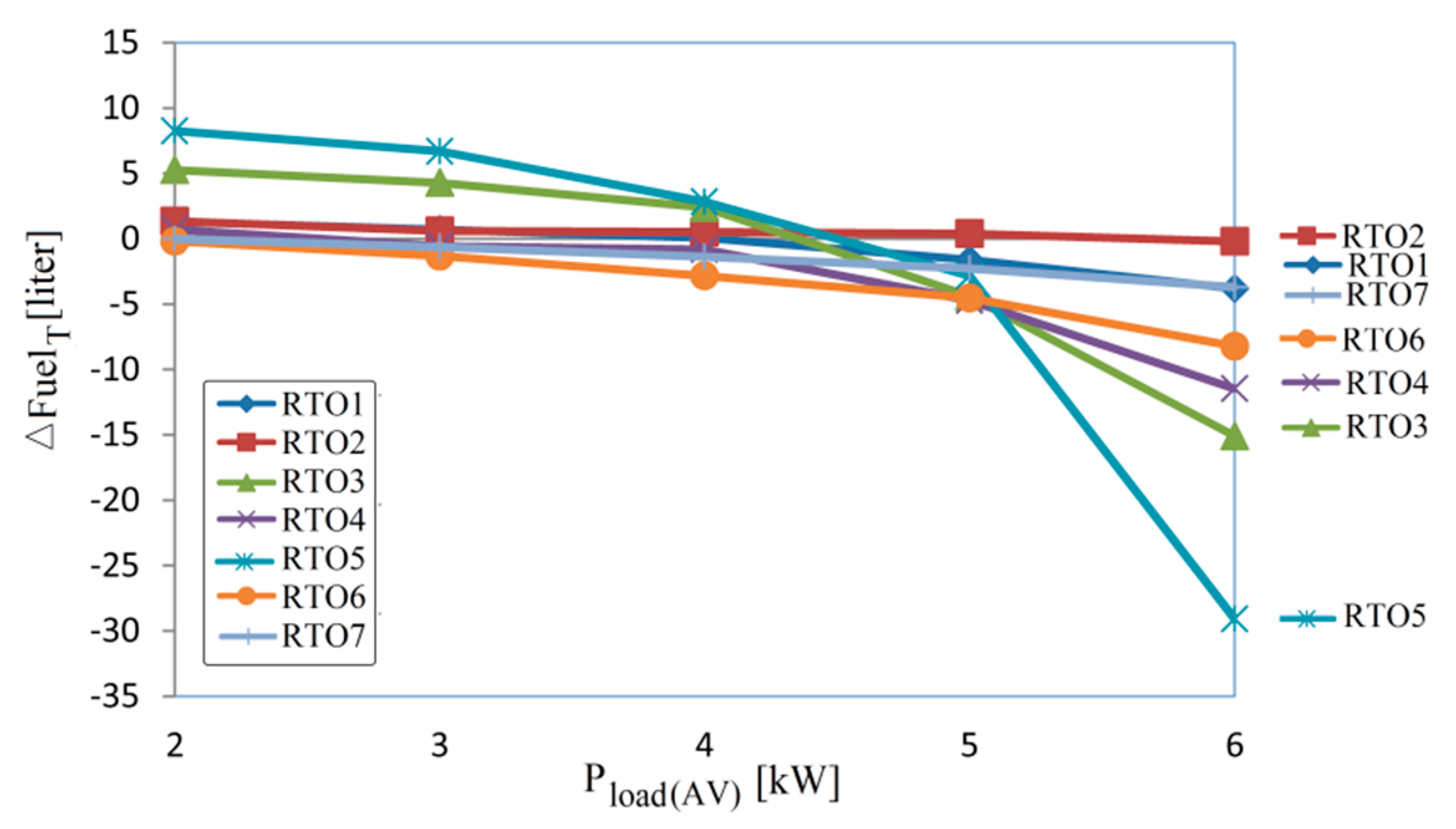
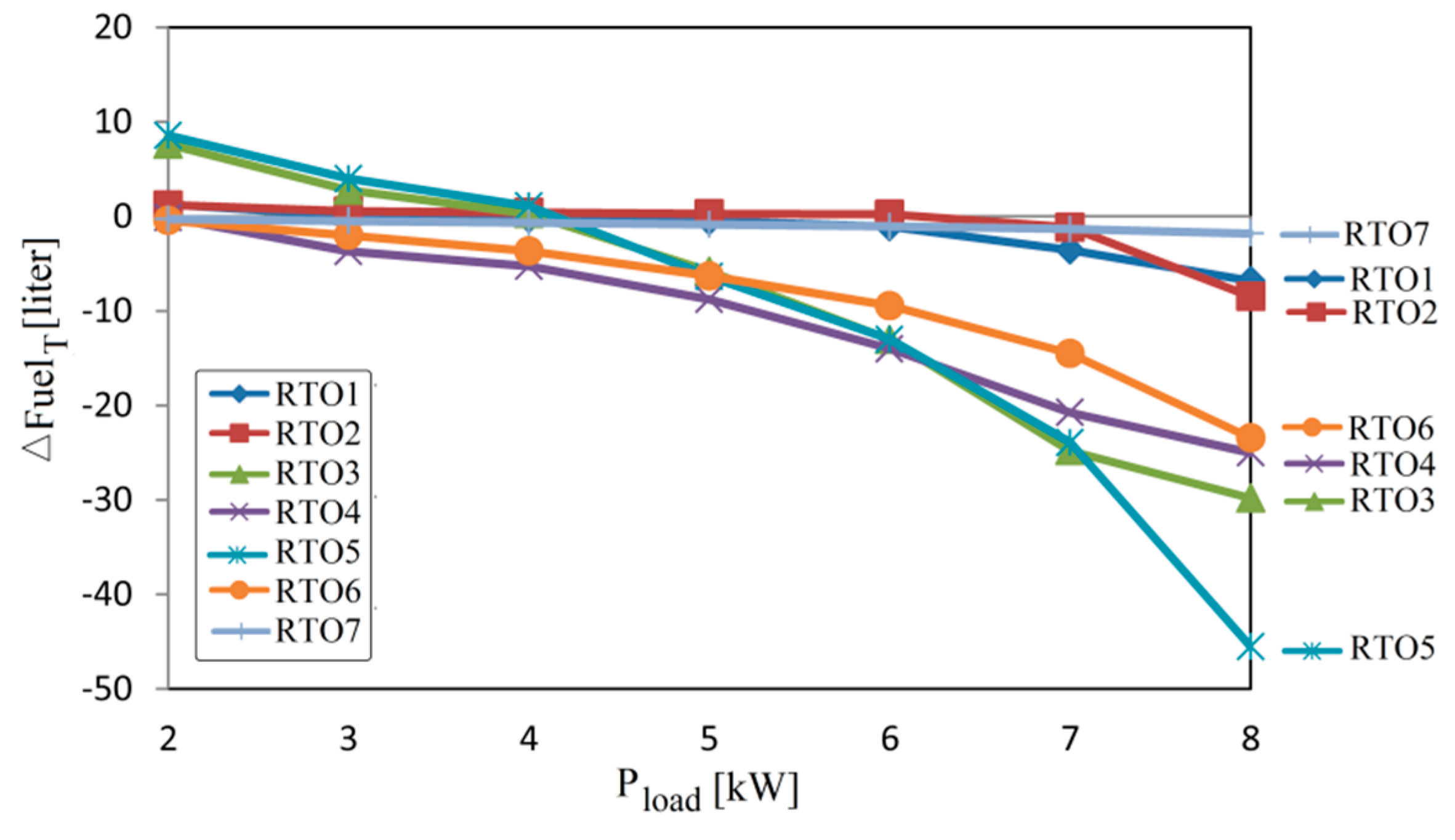
The goal of this study is to identify which is the best RTO strategy in full range of load demand or the best two RTO strategies that can be used for high and low values of the load demand, respectively.
The obtained results reveal that the fuel economy is better (in comparison with the sFF strategy) for only two RTO strategies, if the FCHPS is operated using the same strategy in the full range of load demand. If the FCHPS is operated using the best RTO strategy for high values of the load demand and another one which is best in the rest of the load range, then more combinations are possible (which we refer to as the switching strategies). This is because two RTO strategies are identified as best for high levels of load and two others as best for low load.
The rest of this study is organized as follows. The modeling of the FCHPS, the Energy Management Unit implementing the RPF-control mode and the optimization loops, and setting of the RTO strategies are presented in Section 2. The fuel economy obtained using a RTO strategy for the FCHPS is discussed in Section 3. Th final section concludes the performed study by highlighting the main findings and next work.

2. The Energy Management Unit of the Fuel Cell Hybrid Power System

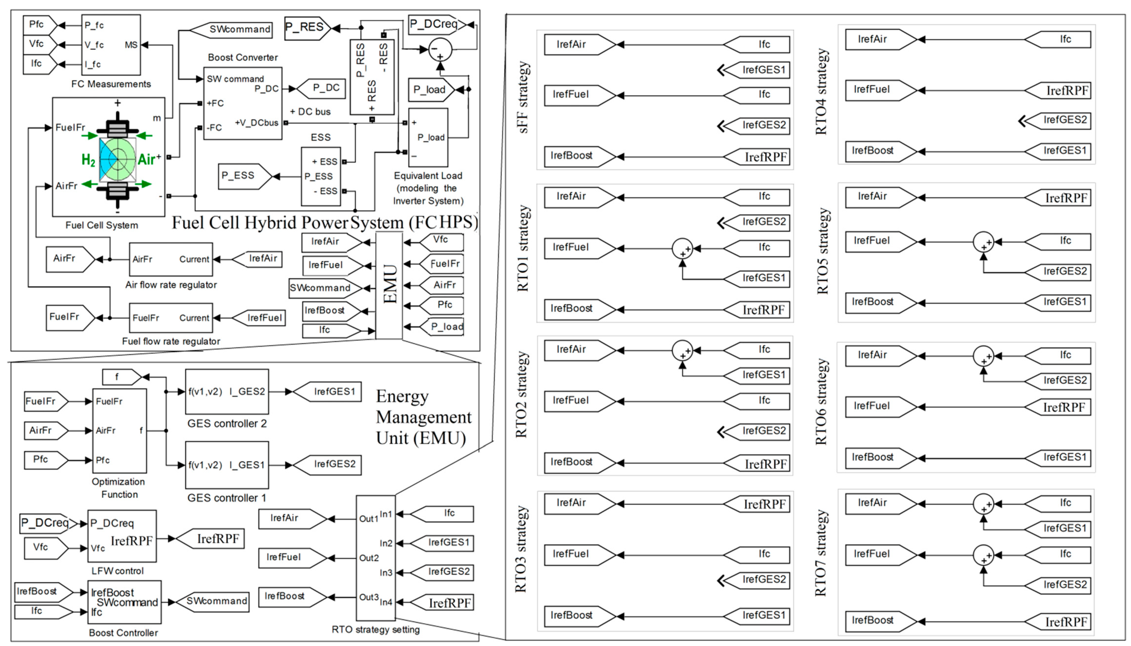
The diagram of the FCHPS Energy Management Unit (EMU) is presented in Figure 1. The setting block will select one of the RTO strategies proposed in the literature [17,29,38,44,56,57,58,59] (see the right side of the Figure 1 and Table 1, where the references are mentioned in the last column) in order to evaluate the fuel economy under the same load profile.
The performance under constant load could be measured by different indicators, such as the generated FC net power ( P F C n e t ) or the fuel consumption efficiency ( F u e l e f f P F C n e t /   F u e l F r ), which are both important to be optimized. Thus, the optimization function used in this study will linearly mix these performance indicators as below:
f ( x , A i r F r , F u e l F r , p l o a d ) = P F C n e t + k f u e l F u e l e f f
where x is the state vector, pload the disturbance, and the fuel flow rate (FuelFr) and the air flow rate (AirFr) are the control variables of the FC power. Also, note that another way to control the generated FC power on the DC bus is via the boost DC–DC converter, which is usually used as an interface for the FC system to the DC bus. So, three input control variables of the FC system will be considered in this study to control the FC net power generated on the DC bus.
The objective is to maximize the optimization function (1). The weighting coefficient kfuel [liters per minute (lpm)/W] will be adjusted to explore the best fuel savings obtained for all RTO strategies using constant load and variable profile for the load.
The dynamics of the FCHPS is set by the smooth function g:
x ˙ = g ( x , A i r F r , F u e l F r , p L o a d ) , x X
where the time constants of the 6 kW/45 V FC system and the 100 Ah/200 V batteries’ stack were set to 0.2 s and 10 s, and the equivalent series resistor of the 100 F ultracapacitors’ stack to 0.01 Ω. The DC voltage reference is set to 200 V, the ultracapacitors’ stack has 100 V initial voltage and 10 kΩ parallel resistor (being connected via a bidirectional DC–DC to the DC bus and controlled to regulate the DC voltage), and the batteries’ stack has an 80% initial State-of-Charge (SOC) (being connected directly to the 200 V DC bus).
The losses in the FC system are mainly given by the air compressor, so the FC net power is:
P F C n e t P F C     P c m
where P R E S is the FC power, the P c m is the air compressor power [60]:
P c m = I c m V c m = ( a 2 A i r F r 2 + a 1 A i r F r + a 0 ) ( b 1 I F C + b 0 )
and the coefficients are [60,61]: a 0 = 0.6 a 1 = 0.04 a 2 = 0.00003231 b 0 =   0.9987 , and b 1 =   46.02 . The dynamics of the air compressor is modeled through a second order system with 100 Hz natural frequency and 0.7 damping ratio [60].
Note that in a Renewable FCHPS the variable profile from the available Renewable Energy Sources ( P R E S ) can also be considered as disturbance as well. But both variable power profiles can be considered together by using a single disturbance, referred to as the power requested on the DC bus ( P D C r e q = P l o a d P R E S > 0 ). When P D C r e q = P l o a d P R E S < 0 , an excess of RES power is available on the DC bus, which, for example, can be used to supply an electrolyzer in order to generate hydrogen and then store it in tanks. So, during the excess of power on the DC bus ( P R E S > P l o a d ), the FC system will operate in standby mode, but during a lack of power on the DC bus ( P R E S < P l o a d ) then the FC system must compensate the power flow balance on the DC bus by generating on average (AV) the FC net power, P F C n e t ( A V ) , instead of taking this power ( P D C r e q ( A V ) ) from the batteries’ stack, where:
P F C n e t ( A V ) =   I F C ( A V ) V F C n e t ( A V ) P D C r e q ( A V ) η b o o s t
Consequently, based on the power flow balance on the DC bus (5):
C D C u D C d u D C d t = η b o o s t p F C n e t + p E S S p D C r e q
the average of the pESS power is zero ( P E S S ( A V )   0 ), where pESS is the output power of the hybrid battery/ultracapacitors ESS.
So, the size of the batteries stack can be further reduced or even be eliminated, with only the ultracapacitors’ stack remaining to dynamically compensate the lack or excess of power on the DC bus, due to load pulses or sharp variation in the load demand or the RES power. Note that the capacitor CDC connected on DC bus is used only to filter the ripple of the DC voltage (udc). The regulation of the DC voltage to 200 V is easily done by controlling the bidirectional DC–DC converter of the ultracapacitors’ stack.
So, summarizing the above presented RTO strategy, P E S S ( A V )   0 if the FC system is to be operated in the RPF-control mode using the reference current I r e f ( R P F ) to control the FC power (as much as necessary to comply the power flow balance on the DC bus), then:
I r e f ( R P F ) I F C ( A V ) = P D C r e q ( A V ) η b o o s t V F C n e t ( A V )
Note that promising results have been achieved for the Renewable FCHPSs using the RPF- control mode on the FC system [55,61]. For a clear comparison of the RTO strategies but without losing the generality of this study, the proposed RPF-control mode of the FC system will be analyzed for a FCHPS without variable RES power ( P R E S = 0 ). So, as explained before, the disturbance in the FCHPS will be represented by the load power ( P D C r e q = P l o a d ).
The RPF-control mode for the FC system can be obtained by controlling the boost DC–DC converter ( I r e f ( R P F ) = I r e f ( b o o s t ) ), the AirFr regulator ( I r e f ( R P F ) = I r e f ( A i r ) ), or the FuelFr regulator ( I r e f ( R P F ) = I r e f ( F u e l ) ).
For example, controlling the boost DC–DC converter, the 0.1 A hysteretic controller of the boost converter will ensure I r e f ( R P F ) = I r e f ( b o o s t )     I F C , so the FC system will be operated in the RPF-control mode based on (6).
The other two control variables, FuelFr and AirFr, will be set based on (7) [56]:
F u e l F r = 60000 R ( 273 + θ ) N C I r e f ( F u e l ) 2 F ( 101325 P f ( H 2 ) ) ( U f ( H 2 ) / 100 ) ( x H 2 / 100 )
A i r F r = 60000 R ( 273 + θ ) N C I r e f ( A i r ) 4 F ( 101325 P f ( O 2 ) ) ( U f ( O 2 ) / 100 ) ( y O 2 / 100 )
where the signals I r e f ( F u e l ) and I r e f ( A i r ) are the references used to optimize the FCHPS.
The FC parameters ( N C , θ , U f ( H 2 ) , U f ( O 2 ) ,   P f ( H 2 ) , P f ( O 2 ) , x H 2 , y O 2 ) are set to default values of the 6 kW/45 V FC system, and R = 8.3145 J/(mol K) and F = 96,485 As/mol are two well-known constants [62].
For safety reasons in the FC system operation, the slope of the signals Iref(Fuel) and Iref(Air) have been limited to 100 A/s. This will limit the response time of the FC system to generate the requested DC power set by (4) in order to compensate the power flow balance on the DC. For example, if the FC system operates in a stationary regime generating 5 kW at about 50 V, and it must pass in 8 kW generating regime due to step-up in load demand, then the transitory regime will be of about 0.6 s (3000 W/50 V = 60 A and 60 A/100 A/s = 0.6 s). In this case, the response time of the FC system is limited by the 100 A/s slope, not by the 0.2 s FC constant time. So, the ESS must be appropriately designed to ensure such transitory regimes, which could arise in driving the FC vehicles. But if this design is performed considering all potential cases, then the FCHPS will operate properly under an unknown profile of load demand and then the optimization problem can be approached in real-time based on Global Extremum Seeking (GES) control.
For example, in the RTO7 strategy, both control variables, FuelFr and AirFr, are used to optimize the FCHPS, considering the GES references I r e f ( G E S 1 ) and I r e f ( G E S 2 ) generated by the two GES controllers. The searching signals I r e f ( F u e l ) and I r e f ( A i r ) will be given by I r e f ( F u e l ) = I r e f ( G E S 2 ) + I F C and I r e f ( A i r ) = I r e f ( G E S 1 ) + I F C . The optimum on the optimization surface is close to the operating point of the FCHPS using the reference strategy, which is usually implemented in FC systems and is referred to in the literature as the Static Feed-Forward (sFF) strategy [56]. Thus, the searching area is limited around the FC current set by the RPF-control mode ( I F C     I r e f ( R P F ) ) in order to speed up the searching process. So, in less than 10 dither’s periods, the optimum will be found, which means up to 100 milliseconds for 100 Hz sinusoidal dither. The searching time is, therefore, in the order of the FC time constant and the FC system reacting to changes in both inputs control variables, FuelFr and AirFr.
Instead, only one control variable is used by the strategies RTO1 and RTO2 in search of the optimum, as follows: I r e f ( F u e l ) = I r e f ( G E S 2 ) + I F C and I r e f ( A i r ) = I r e f ( G E S 1 ) + I F C . The other control variable is set to I F C     I r e f ( R P F ) in order to speed up the searching process.
The RPF-control mode of the FC system is obtained by setting I r e f ( A i r ) = I r e f ( R P F )     I F C for the strategies RTO3 and RTO5. In the same manner for the strategies RTO4 and RTO6, the RPF-control mode of the FC system is obtained by setting I r e f ( F u e l ) = I r e f ( R P F )     I F C . Only the boost controller is used in search of the optimum by the RTO3 strategy and the RTO4 strategy, so I r e f ( b o o s t ) = I r e f ( G E S 1 )     I F C and I r e f ( b o o s t ) =   I r e f ( G E S 2 )     I F C due to low value of the hysteresis band of 0.1 A. The other control variable in the RTO3 strategy and the RTO4 strategy, which is I r e f ( F u e l ) and I r e f ( A i r ) , respectively, is set to I F C     I r e f ( R P F ) in order to speed up the searching process. So, the searching for the optimum is performed on the optimization curve, which is a multimodal function to the FC current.
On the other hand, the strategies RTO5 and RTO6 use a second control variable in searching for the optimum (which is I r e f ( F u e l ) = I r e f ( G E S 2 ) + I F C and I r e f ( A i r ) = I r e f ( G E S 1 ) + I F C ), besides the control variable I r e f ( b o o s t ) . So, in this case, the searching for the optimum is performed on the multimodal optimization surface.
Thus, seven possible RTO strategies will be analyzed in this study, compared to sFF strategy as a reference. All RTO strategies use the GES control scheme proposed in [20] to find the optimum of the optimization function in case of k f u e l set to 0, 25, and 50 [lpm/W].
The interested reader can search the following references [17,29,38,44,56,57,58,59] for the hybrid system configuration, the control block diagrams, and the setting used for each strategy analyzed in this study.
The GES control has been implemented based on [20]. The interested reader, in the design of the GES control, can find design examples in [63,64]. In this study, the following values are used for the GES parameters: k1 = 1, k2 = 2, k N p =   20 , k N y =   1 / 100 0 , fd1 = 100 Hz and fd2 = 200 Hz, and bh = 0.1 and bl = 1.5 for the cut-off frequencies (bh fd and bl fd) of the band-pass filter.

3. Results

Each RTO strategy has been analyzed using the FCHPS diagram shown in Figure 1 and control loops setting listed in Table 1.
The hydrogen consumption during a load cycle is evaluated for each RTOk strategy (k = 1 ÷ 7) using the performance indicator F u e l T = F u e l F r ( t ) d t (measured in liter [L]) and the fuel economy compared to sFF strategy, Δ F u e l T k =   F u e l T k   F u e l T 0 , is listed in Table 2, Table 3 and Table 4.

3.1. Constant Load

The fuel savings for each RTOk strategy compared to sFF strategy ( Δ F u e l T k =   F u e l T k   F u e l T 0 , k = 1 ÷ 7) is listed in Table 2, Table 3 and Table 4 for kfuel = 0, kfuel = 25, and kfuel = 50 and different values of the constant load (Pload mentioned in first column of the Table 2, Table 3 and Table 4). The second column of the Table 2, Table 3 and Table 4 mentions for the sFF strategy the hydrogen consumption (FuelT0) during a load cycle.
The fuel economy ( Δ F u e l ) for all RTOk strategy (k = 1 ÷ 7) are presented in Figure 2, Figure 3 and Figure 4 for kfuel = 0, kfuel = 25, and kfuel = 50.
In case of kfuel = 0 (see Figure 2), the optimization function will be f ( x , A i r F r , F u e l F r , P L o a d ) = P F C n e t , so the optimization objective is to increase the FC net power. Thus, the fuel savings will be higher in the case of kfuel ≠ 0 (see Table 3 and Table 4 compared to Table 2) because the optimization function f ( x , A i r F r , F u e l F r , P L o a d ) = P F C n e t + k f u e l F u e l e f f takes in consideration the efficiency of the fuel consumption ( F u e l e f f ). It is worth mentioning that the fuel economy does not increase by increasing the value of the kfuel parameter (see Table 4 compared to Table 3). In fact, a sensitivity analysis of the fuel economy to values of the kfuel parameter in range 0 to 50 has been revealed the multimodal variation of the fuel economy for all RTO strategy. Based on this analysis performed in other work, the best economy can be obtained for a value of the kfuel parameter in range 20 to 30, but this is not the goal of the work shown here. As mentioned before, the goal is to identify which is the best RTO strategy in the full range of load demand or the best two RTO strategies that can be used: one in the range of high load demand and the other in the rest of range (of low load demand), respectively.
The analysis of Figure 2, Figure 3 and Figure 4 highlights the best strategies for high load demand (Pload = 8 kW), rated load demand (Pload = 6 kW), and low load demand (Pload ≤ 5 kW).
In the case of kfuel = 25 (see Figure 3) the order of the RTO strategies (starting with that which gives the best fuel economy) is as follows:
  • RTO5, RTO6, RTO3, and RTO4 for Pload = 8 kW;
  • RTO5, RTO3, RTO4, and RTO6 for Pload = 6 kW;
  • RTO4 and RTO6 for Pload ≤ 5 kW;
It is worth mentioning this order in the case of kfuel = 0 and kfuel = 50.
In the case of kfuel = 0 (see Figure 2) the order of the RTO strategies (starting with that which gives the best fuel economy) is as follows:
  • RTO5, RTO3, RTO6, and RTO4 for Pload = 8 kW;
  • RTO5, RTO6, RTO4, and RTO3 for Pload = 6 kW;
  • RTO6 and RTO4 for Pload ≤ 5 kW;
In the case of kfuel = 50 (see Figure 4) the order of the RTO strategies (starting with that which gives the best fuel economy) is as follows:
  • RTO5, RTO3, RTO4, and RTO6 for Pload = 8 kW;
  • RTO4, RTO5, RTO3, and RTO6 for Pload = 6 kW;
  • RTO4 and RTO6 for Pload ≤ 5 kW;
Note that the same RTO strategies are in the first four positions for Pload = 8 kW and Pload = 6 kW when kfuel = 0, kfuel = 25, and kfuel = 50. The strategies RTO4 and RTO6 are between these four positions, but also are in the first two positions for Pload ≤ 5 kW. So, the strategies RTO4 and RTO6 can be used to optimize the FCHPS operating in the entire loading range. It is difficult to say which is the recommended strategy for variable load demand. So, more tests will be performed in the next section.
Also, it is worth mentioning that the strategies RTO5 and RTO3 cannot be used for Pload ≤ 5 kW due to low performance compared to other RTO strategies (such as the strategies RTO4 and RTO6, for example). So, it is clear that a switching (SW) strategy (which will use the strategies RTO4 and RTO6 for Pload ≤ 5 kW and the strategies RTO5 and RTO3 for Pload > 5 kW) can improve the obtained fuel economy, as compared to the case of one RTO strategy being used in the full range of load demand. The following SW strategies are identified based on the above results:
  • SW1 strategy, which will use the strategies RTO6 and RTO5 for P l o a d 5   kW and P l o a d   >   5   kW , respectively;
  • SW2 strategy, which will use the strategies RTO4 and RTO5 for P l o a d 5   kW and P l o a d >   5   kW , respectively;
  • SW3 strategy, which will use the strategies RTO6 and RTO3 for P l o a d 5   kW and P l o a d >   5   kW , respectively;
  • SW4 strategy, which will use the strategies RTO4 and RTO3 for P l o a d 5   kW and P l o a d >   5   kW , respectively;
The strategies SW1, SW2, and SW3 request two GES controllers, due to the use of strategies RTO6 and RTO5, instead of one GES controller as for SW4 strategy.

3.2. Variable Load

The profile chosen for the variable load is of the scale up and down type with the following constant levels within 4 s: 0.75 Pload(AV), 1.25 Pload(AV), and Pload(AV). Thus, the average value (AV) of the variable load profile is Pload(AV) = (0.75 Pload(AV)⋅4 s + 1.25 Pload(AV)⋅4 s + Pload(AV)⋅4 s)/12 s, where Pload(AV) is mentioned in the first column of Table 5, Table 6 and Table 7. The second column of the Table 5, Table 6 and Table 7 mentions the hydrogen consumption during the variable load cycle for the sFF strategy (FuelT0).
The fuel economy Δ Fuel Tk =   Fuel Tk   Fuel T 0 for each RTOk strategy (k = 1 ÷ 7) compared to commercial strategy, such as the sFF strategy is listed in Table 4, Table 5 and Table 6 for kfuel =0, kfuel = 25, and kfuel = 50.
The fuel economy ( Δ Fuel ) mentioned in Table 4, Table 5 and Table 6 for all RTOk strategy (k = 1 ÷ 7) are presented in Figure 5, Figure 6 and Figure 7 for kfuel = 0, kfuel = 25, and kfuel = 50, using Pload(AV) as variable.
Analysis of the Figure 5, Figure 6 and Figure 7 highlights the same best four strategies for the load profile with Pload(AV) > 5 kW (as in case of P l o a d >   5   kW ). This validates the results obtained for constant load.
Besides the strategies RTO5 and RTO3, it also appears that the RTO4 strategy cannot be used for Pload(AV) ≤ 5 kW due to low performance compared to strategy RTO6 for variable load. So, the SW strategies that remain to be tested, compared to strategy RTO6 (which still ensure fuel saving for different P l o a d ( A V ) ) are as follows:
  • SW1 strategy, which will use the strategies RTO6 and RTO5 for P l o a d 5   kW and P l o a d >   5   kW , respectively;
  • SW3 strategy, which will use the strategies RTO6 and RTO3 for P l o a d 5   kW and P l o a d >   5   kW , respectively;
These results validate the aforementioned conclusions for constant load.

4. Conclusions

Seven control topologies are identified based on the three ways (inputs) to regulate the FC power: via the FC boost converter, and via the fueling regulators. One of these inputs will control the generated FC net power, ensuring the DC power flow balance under variable load. The other two or only one are used for optimization the FC system in order to minimize the fuel consumption. Thus, seven strategies are analyzed for an FC system under constant and variable load demand.
The conclusions of the analysis performed for all strategies are as follows:
  • The strategies RTO3 and RTO5 have been identified as best strategies to operate the FC hybrid power system in the high range of the load demand; both strategies control the air flow regulator to obtain the RPF-control mode for the FC system;
  • The strategies RTO4 and RTO6 have been identified as best strategies to operate the FC hybrid power system in the low range of the load demand; both strategies control the fuel flow regulator to obtain the RPF-control mode for the FC system;
  • The RTO6 strategy has been identified as best strategy to operate the FC hybrid power system under variable load in the entire loading range;
  • The fuel economy will be improved by using the switching strategies under variable load in the entire loading range.
The next work will be focused on comparative analysis of fuel economy for the four switching strategies identified, using the RTO6 strategy as reference. Besides the RTO6 strategy (which uses two GES controllers), the RTO4 strategy (which uses only one GES controller) can become a possible strategy in the low range of load demand, due to simple implementation and minor differences in fuel economy compared to RTO6 strategy under constant load. The cases of strategies SW2 and SW4 remain to be further analyzed in order to decide which strategy is best from different points of view: performance, cost, complexity of implementation. For example, the cost and complexity of implementation is lower for the SW4 strategy compared to strategies SW1, SW2, and SW3 due to the use of one GES controller instead of two GES controllers. The threshold of the load demand (which will be used in switching strategies to split the loading range) will be set after a sensitivity analysis for all switching strategies using a threshold in the range of 4 kW to 6 kW.

Author Contributions

Conceptualization, Methodology, and Validation: N.B., V.A.S., A.C.C.; Writing—Review & Editing: V.A.S.; A.C.C., N.B.

Acknowledgments

This work was supported by a grant of the CNCS/CCCDI-UEFISCDI within “Brancusi” European and international cooperation, PN-III P3-3.1, project “Global Maximum Power Point Tracking algorithms for Photovoltaic Systems under rapid changes in climatic conditions”.

Conflicts of Interest

The authors declare no conflict of interest.

References

  1. Gielen, D.; Boshell, F.; Saygin, D.; Bazilian, M.D.; Wagner, N.; Gorini, R. The role of renewable energy in the global energy transformation. Energy Strateg. Rev. 2019, 24, 38–50. [Google Scholar] [CrossRef]
  2. Liu, Z.; Kendall, K.; Yan, X. China Progress on Renewable Energy Vehicles: Fuel Cells, Hydrogen and Battery Hybrid Vehicles. Energies 2019, 12, 54. [Google Scholar] [CrossRef]
  3. Ou, K.; Yuan, W.-W.; Choi, M.; Yang, S.; Jung, S.; Kim, Y.-B. Optimized power management based on adaptive-PMP algorithm for a stationary PEM fuel cell/battery hybrid system. Int. J. Hydrogen Energy 2018, 43, 15433–15444. [Google Scholar] [CrossRef]
  4. Rafique, M.K.; Haider, Z.M.; Mehmood, K.K.; Zaman, M.S.U.; Irfan, M.; Khan, S.U.; Kim, C.-H. Optimal Scheduling of Hybrid Energy Resources for a Smart Home. Energies 2018, 11, 3201. [Google Scholar] [CrossRef]
  5. Liu, T.; Zhang, D.; Wang, S.; Wu, T. Standardized modelling and economic optimization of multi-carrier energy systems considering energy storage and demand response. Energy Convers. Manag. 2019, 182, 126–142. [Google Scholar] [CrossRef]
  6. Chen, H.; Yang, C.; Deng, K.; Zhou, N.; Wu, H. Multi-objective optimization of the hybrid wind/solar/fuel cell distributed generation system using Hammersley Sequence Sampling. Int. J. Hydrogen Energy 2017, 42, 7836–7846. [Google Scholar] [CrossRef]
  7. Bizon, N. Hybrid power sources (HPSs) for space applications: Analysis of PEMFC/Battery/SMES HPS under unknown load containing pulses. Renew. Sustain. Energy Rev. 2019, 105, 14–37. [Google Scholar] [CrossRef]
  8. Wang, F.-C.; Hsiao, Y.-S.; Yang, Y.-Z. The Optimization of Hybrid Power Systems with Renewable Energy and Hydrogen Generation. Energies 2018, 11, 1948. [Google Scholar] [CrossRef]
  9. Huang, Y.; Wang, H.; Khajepour, A.; Li, B.; Ji, J.; Zhao, K.; Hu, C. A review of power management strategies and component sizing methods for hybrid vehicles. Renew. Sustain. Energy Rev. 2018, 96, 132–144. [Google Scholar] [CrossRef]
  10. Wu, W.; Partridge, J.S.; Bucknall, R.W.G. Simulation of a stabilised control strategy for PEM fuel cell and supercapacitor hybrid propulsion system for a city bus. Int. J. Hydrogen Energy 2018, 43, 19763–19777. [Google Scholar] [CrossRef]
  11. Wang, F.-C.; Lin, K.-M. Impacts of Load Profiles on the Optimization of Power Management of a Green Building Employing Fuel Cells. Energies 2019, 12, 57. [Google Scholar] [CrossRef]
  12. Guo, C.; Lu, J.; Tian, Z.; Guo, W.; Darvishan, A. Optimization of critical parameters of PEM fuel cell using TLBO-DE based on Elman neural network. Energy Convers. Manag. 2019, 183, 149–158. [Google Scholar] [CrossRef]
  13. Araya, S.S.; Zhou, F.; Sahlin, S.L.; Thomas, S.; Jeppesen, C.; Kær, S.K. Fault Characterization of a Proton Exchange Membrane Fuel Cell Stack. Energies 2019, 12, 152. [Google Scholar] [CrossRef]
  14. Ahmadi, P.; Torabi, S.H.; Afsaneh, H.; Sadegheih, Y.; Ganjehsarabi, H.; Ashjaee, M. The effects of driving patterns and PEM fuel cell degradation on the lifecycle assessment of hydrogen fuel cell vehicles. Int. J. Hydrogen Energy 2019. [Google Scholar] [CrossRef]
  15. Fragiacomo, P.; De Lorenzo, G.; Corigliano, O. Performance Analysis of an Intermediate Temperature Solid Oxide Electrolyzer Test Bench under a CO2-H2O Feed Stream. Energies 2018, 11, 2276. [Google Scholar] [CrossRef]
  16. Bukar, A.L.; Tan, C.W. A Review on Stand-alone Photovoltaic-Wind Energy System with Fuel Cell: System Optimization and Energy Management Strategy. J. Clean. Prod. 2019. [Google Scholar] [CrossRef]
  17. Bizon, N. Energy optimization of Fuel Cell System by using Global Extremum Seeking algorithm. Appl. Energy 2017, 206, 458–474. [Google Scholar] [CrossRef]
  18. Sulaiman, N.; Hannan, M.A.; Mohamed, A.; Ker, P.J.; Majlan, E.H.; Wan Daud, W.R. Optimization of energy management system for fuel-cell hybrid electric vehicles: Issues and recommendations. Appl. Energy 2018, 228, 2061–2079. [Google Scholar] [CrossRef]
  19. Gherairi, S. Hybrid Electric Vehicle: Design and Control of a Hybrid System (Fuel Cell/Battery/Ultra-Capacitor) Supplied by Hydrogen. Energies 2019, 12, 1272. [Google Scholar] [CrossRef]
  20. Bizon, N. Global Extremum Seeking Control of the Power Generated by a Photovoltaic Array under Partially Shaded Conditions. Energy Convers. Manag. 2016, 109, 71–85. [Google Scholar] [CrossRef]
  21. Bizon, N.; Thounthong, P. Fuel Economy using the Global Optimization of the Fuel Cell Hybrid Power Systems. Energy Convers. Manag. 2018, 173, 665–678. [Google Scholar] [CrossRef]
  22. You, Z.; Wang, L.; Han, Y.; Zare, F. System Design and Energy Management for a Fuel Cell/Battery Hybrid Forklift. Energies 2018, 11, 3440. [Google Scholar] [CrossRef]
  23. De Lorenzo, G.; Andaloro, L.; Sergi, F.; Napoli, G.; Ferraro, M.; Antonucci, V. Numerical simulation model for the preliminary design of hybrid electric city bus power train with polymer electrolyte fuel cell. Int. J. Hydrogen Energy 2014, 39, 12934–12947. [Google Scholar] [CrossRef]
  24. Ahmadi, S.; Bathaee, S.M.T.; Hosseinpour, A.H. Improving fuel economy and performance of a fuel-cell hybrid electric vehicle (fuel-cell, battery, and ultra-capacitor) using optimized energy management strategy. Energy Convers. Manag. 2018, 160, 74–84. [Google Scholar] [CrossRef]
  25. Bizon, N. Real-time optimization strategies of FC Hybrid Power Systems based on Load-following control: A new strategy, and a comparative study of topologies and fuel economy obtained. Appl. Energy 2019, 241C, 444–460. [Google Scholar] [CrossRef]
  26. Arsalis, A.; Georghiou, G.E. A Decentralized, Hybrid Photovoltaic-Solid Oxide Fuel Cell System for Application to a Commercial Building. Energies 2018, 11, 3512. [Google Scholar] [CrossRef]
  27. Tiar, M.; Betka, A.; Drid, S.; Abdeddaim, S.; Tabandjat, A. Optimal energy control of a PV-fuel cell hybrid system. Int. J. Hydrogen Energy 2017, 42, 1456–1465. [Google Scholar] [CrossRef]
  28. Wu, W.; Partridge, J.; Bucknall, R. Development and Evaluation of a Degree of Hybridisation Identification Strategy for a Fuel Cell Supercapacitor Hybrid Bus. Energies 2019, 12, 142. [Google Scholar] [CrossRef]
  29. Bizon, N.; Mazare, A.G.; Ionescu, L.M.; Enescu, F.M. Optimization of the Proton Exchange Membrane Fuel Cell Hybrid Power System for Residential Buildings. Energy Convers. Manag. 2018, 163, 22–37. [Google Scholar] [CrossRef]
  30. Vivas, F.J.; De las Heras, A.; Segura, F.; Andújar, J.M. A review of energy management strategies for renewable hybrid energy systems with hydrogen backup. Renew. Sustain. Energy Rev. 2017, 82, 126–155. [Google Scholar] [CrossRef]
  31. Oberoi, A.S.; Nijhawan, P.; Singh, P. A Novel Electrochemical Hydrogen Storage-Based Proton Battery for Renewable Energy Storage. Energies 2019, 12, 82. [Google Scholar] [CrossRef]
  32. Bizon, N. Effective Mitigation of the Load Pulses by Controlling the Battery/SMES Hybrid Energy Storage System. Appl. Energy 2018, 229, 459–473. [Google Scholar] [CrossRef]
  33. Olatomiwa, L.; Mekhilef, S.; Ismail, M.S.; Moghavvemi, M. Energy management strategies in hybrid renewable energy systems: A review. Renew. Sustain. Energy Rev. 2016, 62, 821–835. [Google Scholar] [CrossRef]
  34. Spanoudakis, P.; Tsourveloudis, N.C.; Doitsidis, L.; Karapidakis, E.S. Experimental Research of Transmissions on Electric Vehicles’ Energy Consumption. Energies 2019, 12, 388. [Google Scholar] [CrossRef]
  35. Won, J.S.; Langari, R. Intelligent energy management agent for a parallel hybrid vehicle-part II: Torque distribution, charge sustenance strategies, and performance results. IEEE Trans. Veh. Technol. 2005, 54, 935–953. [Google Scholar] [CrossRef]
  36. Das, V.; Padmanaban, S.; Venkitusamy, K.; Selvamuthukumaran, R.; Siano, P. Recent advances and challenges of fuel cell based power system architectures and control—A review. Renew. Sustain. Energy Rev. 2017, 73, 10–18. [Google Scholar] [CrossRef]
  37. Mumtaz, S.; Ali, S.; Ahmad, S.; Khan, L.; Hassan, S.Z.; Kamal, T. Energy Management and Control of Plug-In Hybrid Electric Vehicle Charging Stations in a Grid-Connected Hybrid Power System. Energies 2017, 10, 1923. [Google Scholar] [CrossRef]
  38. Bizon, N. Real-time optimization strategy for fuel cell hybrid power sources with load-following control of the fuel or air flow. Energy Convers. Manag. 2018, 157, 13–27. [Google Scholar] [CrossRef]
  39. Ettihir, K.; Boulon, L.; Agbossou, K. Optimization-based energy management strategy for a fuel cell/battery hybrid power system. Appl. Energy 2016, 163, 142–153. [Google Scholar] [CrossRef]
  40. Ijaodola, O.; Ogungbemi, E.; Khatib, F.N.; Wilberforce, T.; Ramadan, M.; Hassan, Z.E.; Thompson, J.; Olabi, A.G. Evaluating the Effect of Metal Bipolar Plate Coating on the Performance of Proton Exchange Membrane Fuel Cells. Energies 2018, 11, 3203. [Google Scholar] [CrossRef]
  41. Bizon, N. Energy Efficiency of Multiport Power Converters used in Plug-In/V2G Fuel Cell Vehicles. Appl. Energy 2012, 96, 431–443. [Google Scholar] [CrossRef]
  42. Liso, V.; Zhao, Y.; Yang, W.; Nielsen, M.P. Modelling of a Solid Oxide Fuel Cell CHP System Coupled with a Hot Water Storage Tank for a Single Household. Energies 2015, 8, 2211–2229. [Google Scholar] [CrossRef]
  43. Sorrentino, M.; Cirillo, V.; Nappi, L. Development of flexible procedures for co-optimizing design and control of fuel cell hybrid vehicles. Energy Convers. Manag. 2019, 185, 537–551. [Google Scholar] [CrossRef]
  44. Bizon, N.; Thounthong, P. Real-time strategies to optimize the fueling of the fuel cell hybrid power source: A review of issues, challenges and a new approach. Renew. Sustain. Energy Rev. 2018, 91, 1089–1102. [Google Scholar] [CrossRef]
  45. Secanell, M.; Wishart, J.; Dobson, P. Computational design and optimization of fuel cells and fuel cell systems: A review. J. Power Sources 2011, 196, 3690–3704. [Google Scholar] [CrossRef]
  46. Raga, C.; Barrado, A.; Miniguano, H.; Lazaro, A.; Quesada, I.; Martin-Lozano, A. Analysis and Sizing of Power Distribution Architectures Applied to Fuel Cell Based Vehicles. Energies 2018, 11, 2597. [Google Scholar] [CrossRef]
  47. Hu, Z.; Li, J.; Xu, L.; Song, Z.; Fang, C.; Ouyang, M.; Dou, G.; Kou, G. Multi-objective energy management optimization and parameter sizing for proton exchange membrane hybrid fuel cell vehicles. Energy Convers. Manag. 2016, 129, 108–121. [Google Scholar] [CrossRef]
  48. Chen, Y.-S.; Lin, S.-M.; Hong, B.-S. Experimental Study on a Passive Fuel Cell/Battery Hybrid Power System. Energies 2013, 6, 6413–6422. [Google Scholar] [CrossRef]
  49. Kim, M.-J.; Peng, H. Power Management and Design Optimization of Fuel Cell/Battery Hybrid Vehicles. J. Power Sources 2007, 165, 819–832. [Google Scholar] [CrossRef]
  50. Koubaa, R.; Krichen, L. Double layer metaheuristic based energy management strategy for a Fuel Cell/Ultra-Capacitor hybrid electric vehicle. Energy 2017, 133, 1079–1093. [Google Scholar] [CrossRef]
  51. De Lorenzo, G.; Fragiacomo, P. Electrical and thermal analysis of an intermediate temperature IIR-SOFC system fed by biogas. Energy Sci. Eng. 2018, 6, 60–72. [Google Scholar] [CrossRef]
  52. Fathabadi, H. Novel fast and high accuracy maximum power point tracking method for hybrid photovoltaic/fuel cell energy conversion systems. Renew. Energy 2017, 106, 232–242. [Google Scholar] [CrossRef]
  53. Bizon, N.; Oproescu, M. Experimental Comparison of Three Real-Time Optimization Strategies Applied to Renewable/FC-Based Hybrid Power Systems Based on Load-Following Control. Energies 2018, 11, 3537. [Google Scholar] [CrossRef]
  54. Eriksson, E.L.V.; Mac, E.; Gray, A. Optimization and integration of hybrid renewable energy hydrogen fuel cell energy systems—A critical review. Appl. Energy 2017, 202, 348–364. [Google Scholar] [CrossRef]
  55. Bizon, N.; Lopez-Guede, J.M.; Kurt, E.; Thounthong, P.; Mazare, A.G.; Ionescu, L.M.; Iana, G.V. Hydrogen Economy of the Fuel Cell Hybrid Power System optimized by air flow control to mitigate the effect of the uncertainty about available renewable power and load dynamics. Energy Convers. Manag. 2019, 179, 152–165. [Google Scholar] [CrossRef]
  56. Pukrushpan, J.T.; Stefanopoulou, A.G.; Peng, H. Control of Fuel Cell Power Systems; Springer: New York, NY, USA, 2004. [Google Scholar]
  57. Bizon, N.; Culcer, M.; Iliescu, M.; Mazare, A.G.; Ionescu, L.M.; Beloiu, R. Real-time strategy to optimize the Fuel Flow rate of Fuel Cell Hybrid Power Source under variable load cycle. In Proceedings of the ECAI–9th Edition of International Conference on Electronics, Computers and Artificial Intelligence, Targoviste, Romania, 29 June–1 July 2017. [Google Scholar] [CrossRef]
  58. Bizon, N.; Culcer, M.; Oproescu, M.; Iana, G.; Ionescu, L.M.; Mazare, A.G.; Iliescu, M. Real-time strategy to optimize the Airflow rate of Fuel Cell Hybrid Power Source under variable load cycle. In Proceedings of the 22rd International Conference on Applied Electronics—APPEL 2017, Pilsen, Czech Republic, 5–6 September 2017. [Google Scholar] [CrossRef]
  59. Bizon, N.; Iana, G.; Kurt, E.; Thounthong, P.; Oproescu, M.; Culcer, M.; Iliescu, M. Air Flow Real-Time Optimization Strategy for Fuel Cell Hybrid Power Sources with Fuel Flow Based on Load-Following. Fuel Cell 2018, 18, 809–823. [Google Scholar] [CrossRef]
  60. Ramos-Paja, C.A.; Spagnuolo, G.; Petrone, G.; Emilio Mamarelis, M. A perturbation strategy for fuel consumption minimization in polymer electrolyte membrane fuel cells: Analysis, Design and FPGA implementation. Appl. Energy 2014, 119, 21–32. [Google Scholar] [CrossRef]
  61. Bizon, N.; Hoarcă, C.I. Hydrogen saving through optimized control of both fueling flows of the Fuel Cell Hybrid Power System under a variable load demand and an unknown renewable power profile. Energy Convers. Manag. 2019, 184, 1–14. [Google Scholar] [CrossRef]
  62. SimPowerSystems TM Reference; Hydro-Québec and the MathWorks, Inc.: Natick, MA, USA, 2010.
  63. Bizon, N.; Thounthong, P.; Raducu, M.; Constantinescu, L.M. Designing and modelling of the asymptotic perturbed extremum seeking control scheme for tracking the global extreme. Int. J. Hydrogen Energy 2017, 42, 17632–17644. [Google Scholar] [CrossRef]
  64. Bizon, N.; Kurt, E. Performance Analysis of Tracking of the Global Extreme on Multimodal Patterns using the Asymptotic Perturbed Extremum Seeking Control Scheme. Int. J. Hydrogen Energy 2017, 42, 17645–17654. [Google Scholar] [CrossRef]
Figure 1. The Fuel Cell Hybrid Power Systems (FCHPS), Energy Management Unit (EMU) and RTO strategy setting block.
Energies 12 01889 g001
Figure 2. Fuel economy for kfuel = 0 and different Pload.
Energies 12 01889 g002
Figure 3. Fuel economy for kfuel = 25 and different Pload.
Energies 12 01889 g003
Figure 4. Fuel economy for kfuel = 50 and different Pload.
Energies 12 01889 g004
Figure 5. Fuel saving for kfuel = 0 and different Pload(AV).
Energies 12 01889 g005
Figure 6. Fuel saving for kfuel = 25 and different Pload(AV).
Energies 12 01889 g006
Figure 7. Fuel saving for kfuel = 50 and different Pload(AV).
Energies 12 01889 g007
Table 1. Real-Time Optimization (RTO) strategies.
StrategyIref(Boost)Iref(Air)Iref(Fuel)Ref.
sFFIref(RPF)IFCIFC[56]
RTO1Iref(RPF)IFCIref(GES2) + IFC[57]
RTO2Iref(RPF)Iref(GES1) + IFCIFC[58]
RTO3Iref(GES1)Iref(RPF)IFC[17]
RTO4Iref(GES2)IFCIref(RPF)[38]
RTO5Iref(GES1)Iref(RPF)Iref(GES2) + IFC[29]
RTO6Iref(GES2)Iref(GES1) + IFCIref(RPF)[59]
RTO7Iref(RPF)Iref(GES1) + IFCIref(GES2) + IFC[44]
Table 2. Fuel economy for kfuel = 0 and different Pload.
PloadFuelT0ΔFuelT1ΔFuelT2ΔFuelT3ΔFuelT4ΔFuelT5ΔFuelT6ΔFuelT7
[kW][L][L][L][L][L][L][L][L]
234.021.221.211.26−0.468−0.42−0.22
356.30.130.794.14−1.226.16−1.7−0.38
474.88−0.130.772.08−2.281.94−3.1−0.54
598.6−0.380.55−0.08−5.6−5.18−5.24−0.72
6125.58−1.380.42−2.28−7.66−11.56−8.48−0.9
7158.34−4.34−0.14−12.16−13.56−24.48−14.04−1.08
8176−11.8−4–28.48–22.92−43.34−27.36−1.38
Table 3. Fuel economy for kfuel = 25 and different Pload.
PloadFuelT0ΔFuelT1ΔFuelT2ΔFuelT3ΔFuelT4ΔFuelT5ΔFuelT6ΔFuelT7
[kW][L][L][L][L][L][L][L][L]
234.021.22−0.0912.14−0.6446.78−0.56−0.352
356.3−0.25−0.245.548−3.8761.76−2−0.6
474.88−0.71−0.251.2−5.176−3.72−3.76−0.88
598.6−1.03−0.46−6.44−8.76−11.42−6.52−1.2
6125.58−2.08−1.58−14.14−12.54−17.82−11.28−1.6
7158.34−10.56−4.24−28.42−24.26−30.24−20.76−2.08
8176−22.92−18.48−31.08−26−47.72−37.98−2.92
Table 4. Fuel economy for kfuel = 50 and different Pload.
PloadFuelT0ΔFuelT1ΔFuelT2ΔFuelT3ΔFuelT4ΔFuelT5ΔFuelT6ΔFuelT7
[kW][L][L][L][L][L][L][L][L]
234.021.281.227.628−0.18.56−0.42−0.28
356.30.10.562.764−3.74−2−0.48
474.88−0.230.420.288−5.2641.1−3.66−0.64
598.6−0.480.28−5.8−8.76−6.34−6.28−0.84
6125.58−1.080.22−13.02−13.98−13−9.42−1.04
7158.34−3.56−1.14−24.82−20.74−23.9−14.48−1.32
8176−6.8−8.48−29.8−25−45.52−23.44−1.8
Table 5. Fuel economy for kfuel = 0 and different Pload(AV).
Pload(AV)FuelT0ΔFuelT1ΔFuelT2ΔFuelT3ΔFuelT4ΔFuelT5ΔFuelT6ΔFuelT7
[kW][L][L][L][L][L][L][L][L]
234.141.31.355.260.78.26−0.180
353.920.710.64.28−0.566.7−1.32−0.62
475.80.070.522.4−0.822.84−2.84−1.36
5100.62−1.60.4−4.38−4.72−2.84−4.52−2.26
6130.2−3.8−0.2−15.08−11.46−29.08−8.22−3.7
Table 6. Fuel economy for kfuel = 25 and different Pload(AV).
Pload(AV)FuelT0ΔFuelT1ΔFuelT2ΔFuelT3ΔFuelT4ΔFuelT5ΔFuelT6ΔFuelT7
[kW][L][L][L][L][L][L][L][L]
234.140.5−0.517.181.9210.8−0.1−0.44
353.92−0.48−0.757.240.828.74−1.04−1.44
475.8−1.8−13.32−0.64−0.26−3.84−2.58
5100.62−3−1.2−3.16−4.16−12.96−9.3−3.98
6130.2−5.3−1.8−13.28−10.08−42.54−18.56−6.18
Table 7. Fuel economy for kfuel = 50 and different Pload(AV).
Pload(AV)FuelT0ΔFuelT1ΔFuelT2ΔFuelT3ΔFuelT4ΔFuelT5ΔFuelT6ΔFuelT7
[kW][L][L][L][L][L][L][L][L]
234.140.51−0.514.53.410.14−0.38−0.34
353.92−0.47−0.7412.72.98.82−1.18−1.22
475.8−1.58−0.973.5−0.54.92−2.88−2.24
5100.62−2.99−1.25−2.34−3.98−9.66−6.2−3.38
6130.2−5.23−1.72−12.08−9.46−37.26−16.38−5.3

