1. Introduction
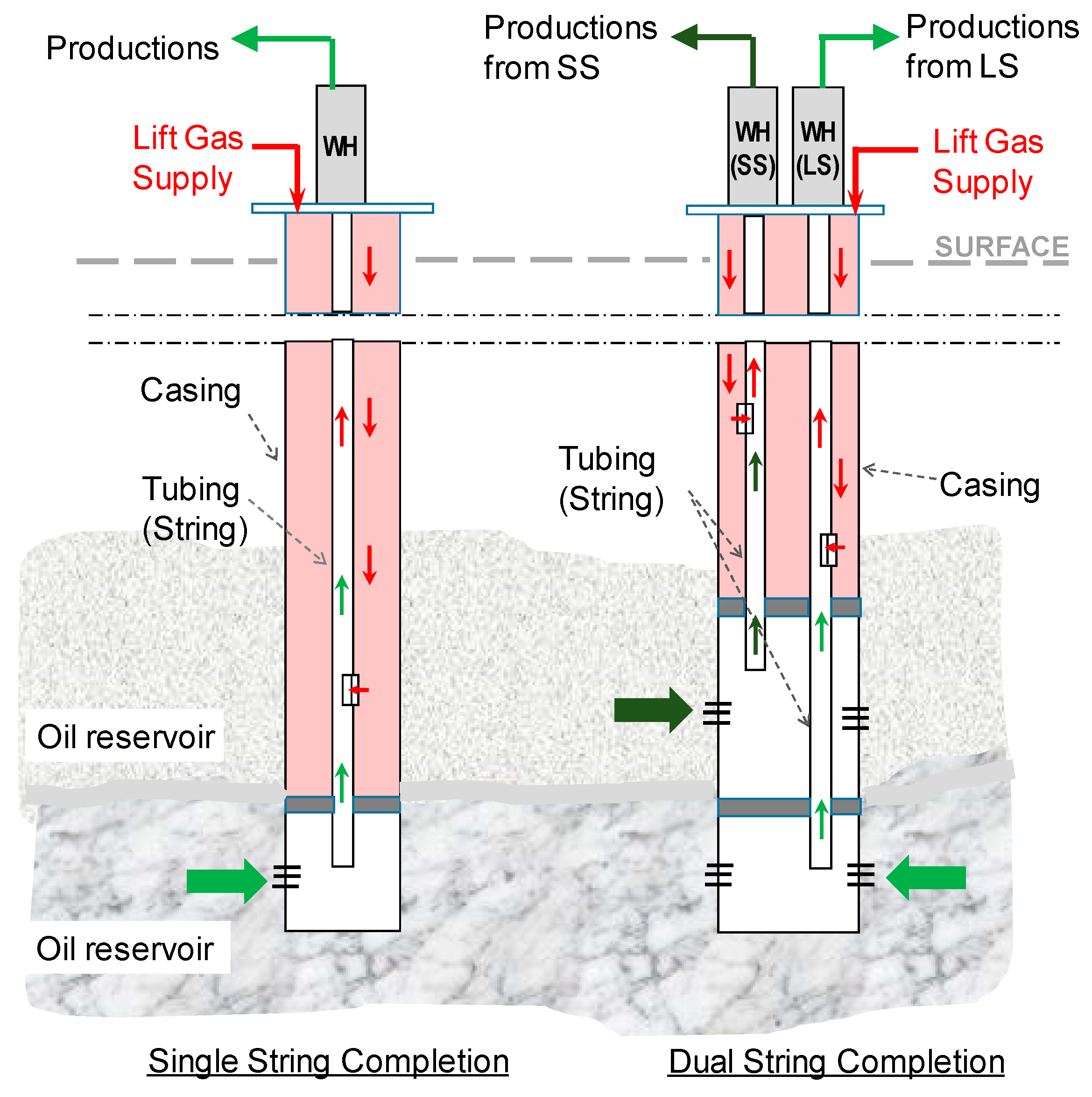
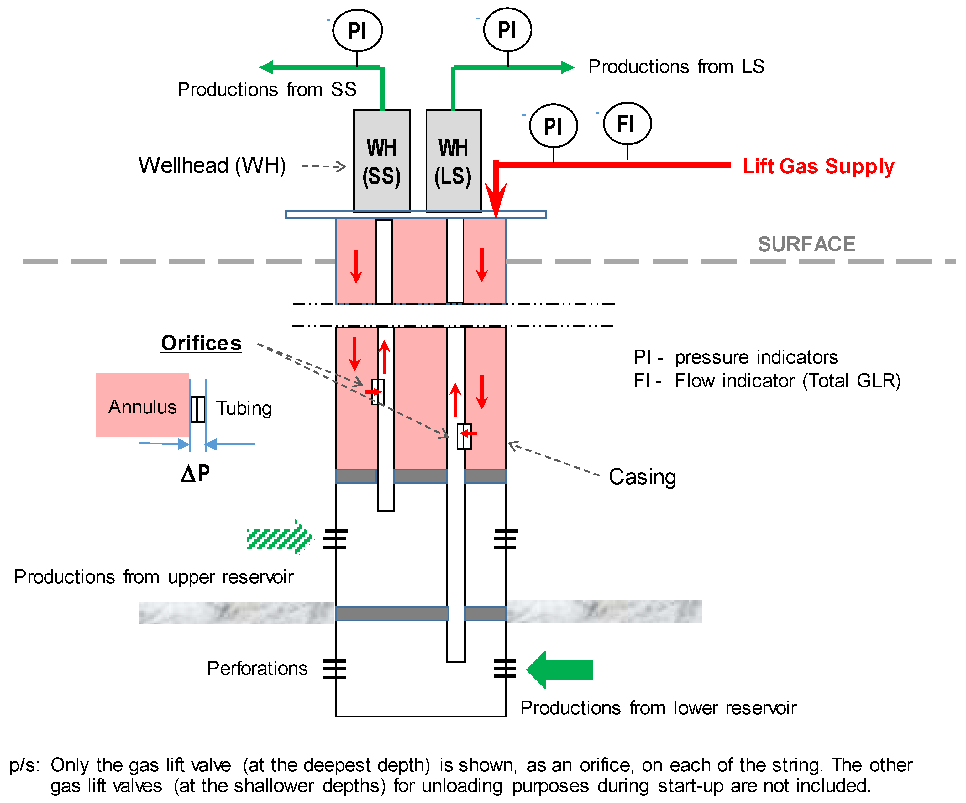
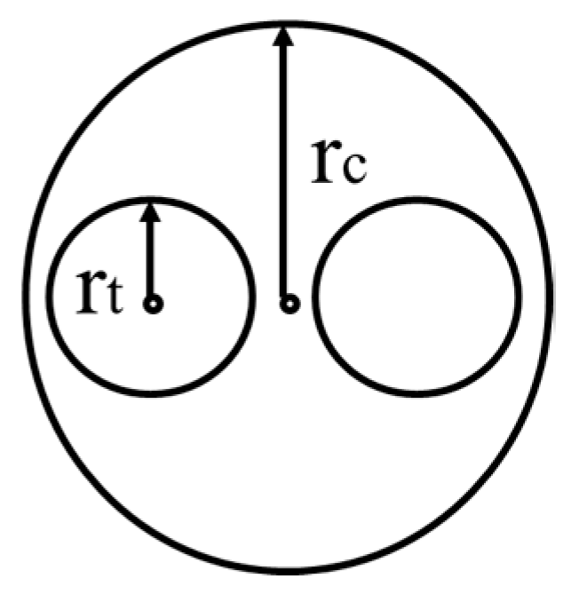
Gas lift is one of the common artificial lift techniques used in upstream oil production. It works by injecting high pressure gas into the annulus and tubing, reducing the fluids density and allowing the fluids to be produced to the surface at a lower bottom-hole pressure. Dual string completion refers to a single well casing housing two tubing, see
Figure 1. The tubings are fitted into the casing side by side with all of the required accessories. Typically, the tubing will be of a different length, with one shorter than the other, to allow production from different zones. The shorter tubing is named Short String (SS), and the longer tubing is named Long String (LS) [
1]. Gas lift is particularly suitable for this type of completion due to the space limitation.
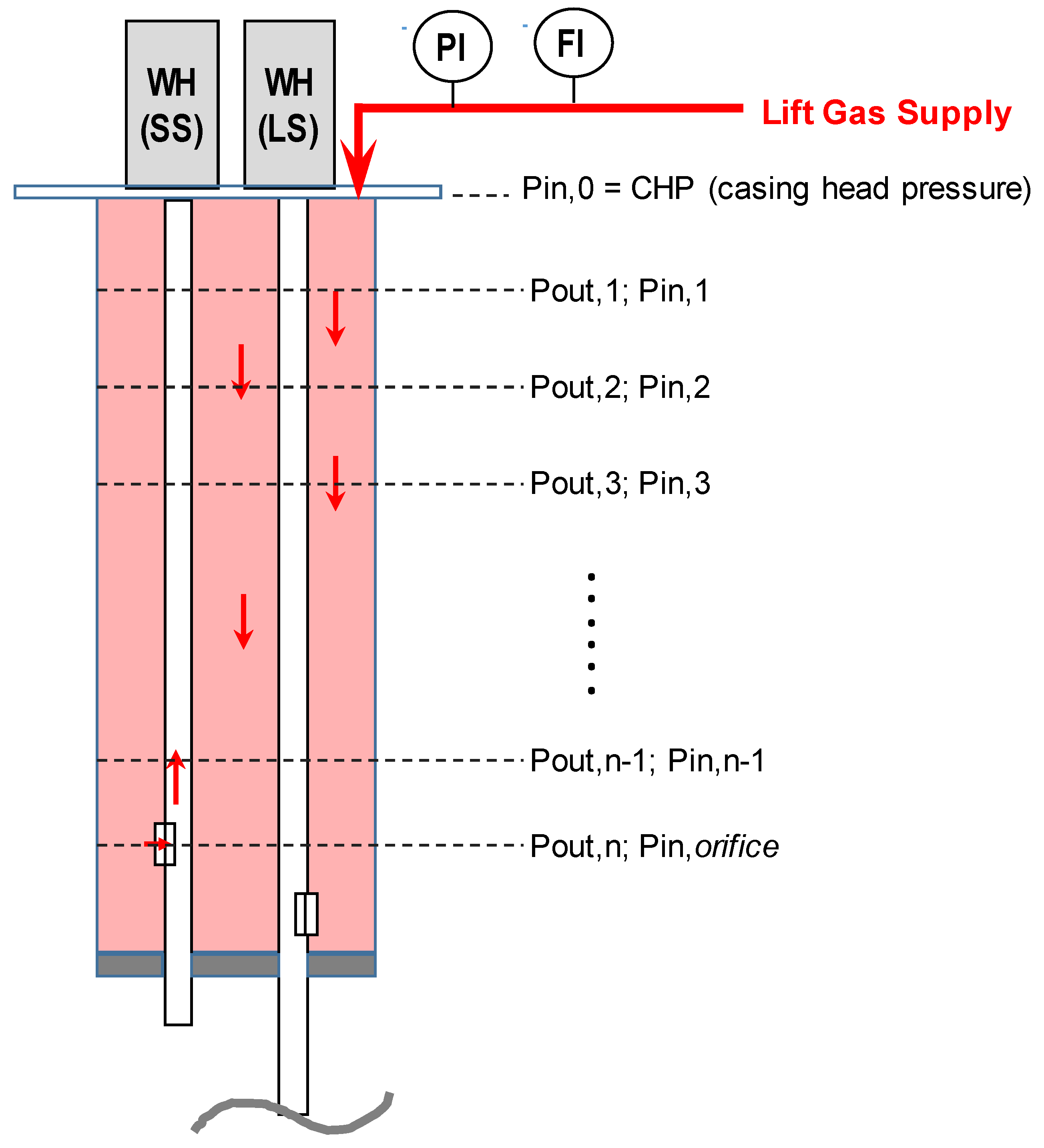
The design of gas lifting for the dual string completion has proven to be a challenge. The total gas injection rate for both strings are measured at the surface, but the amount of the gas going into each tubing is difficult to determine [
2]. This may lead to one of the strings getting too much gas while the other string is starved. This phenomenon is known as gas robbing. Excessive or inadequate injected gas can lead to lower well fluids production and flow instability. At the same time, it is desirable to inject the gas at the optimum level in each string to operate the gas lift system efficiently. Widianoko et al. [
3] suggested placing the orifices for both LS and SS at the same depth to prevent such phenomena. This, however, may not suit the lifting requirement. There is also industry practice that simply assumes an equal split of the gas lift rate (GLIR) between LS and SS, which would hardly be the case, noting that the production behaviour may vary significantly between the two.
While the gas allocation to optimize the oil production from single string completions has been widely discussed by many researchers, the literature on gas lift optimization for dual string completion is scarce. Widianoko et al. [
3] proposed the use of a trial and error technique in the field to maximize the production from the dual string well, but this is easier said than done operationally. Nishikiori et al. [
4] suggested the use of a non-linear optimization method to generate the most optimum gas lift operating condition for a set of multiple single string wells. This is only applicable to a single string well where the determination of GLIR is straightforward. The optimization of the gas lift in a dual string completion would require the computation of the amount of gas going into the individual string, and the consideration of the interaction between the strings as well as with the common annulus. The split factor is defined as the ratio between the gas lift rate (GLIR) for SS and LS over the total gas lift injected. A higher split factor for a particular string means that more gas will be entering that string. This parameter is important for dual string gas lift optimization, ensuring an efficient usage of energy from the produced gas for oil production.
Eikrem et al. [
5] discussed gas lift instability in a single point gas lifted dual string well using both a mathematical model and laboratory measurement. A single point gas injection for both strings does not represent a realistic field operation. In field operations, the SS gas lift injection valve was always placed shallower than that of the LS. Conejeros [
6] proposed to optimize the dual string production by producing water through LS and oil through SS; his work does not consider the gas lift.
Kamis et al. [
2] proposed to use the average of the GLIR for LS and SS obtained from individual well modelling. The method assumed that well tests were carried out on one string at a time while the other string is on production with the stable gas lift. The second string is to be tested immediately or as soon as possible after the first test. This is to maintain similar test conditions for both of the strings, which may not be operationally practical. The calculated gas injection rate from the single well model is matched against the surface measured test rate based on the first string’s parameters. The gasses injection rate for the second string is obtained through a simple deduction from the total gas injected. A similar approach is carried out for the second string. Consequently, each individual string will have its gas lift rate estimated, and the average of the values is then used to estimate the split factor.
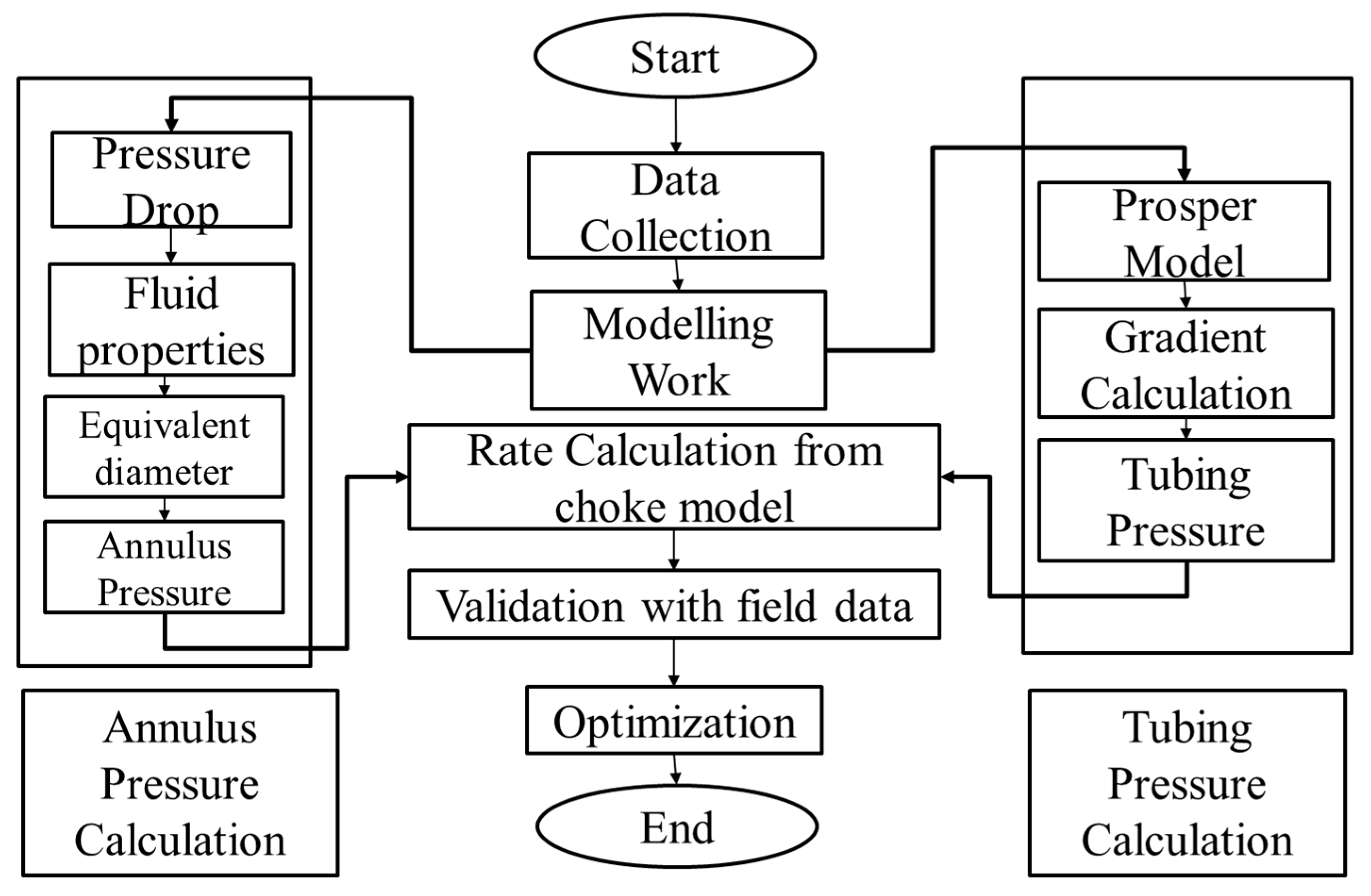
Petroleum Experts (PETEX) proposed two methods to estimate the amount of lift gas going into the LS and SS using their nodal analysis tool, PROSPER [
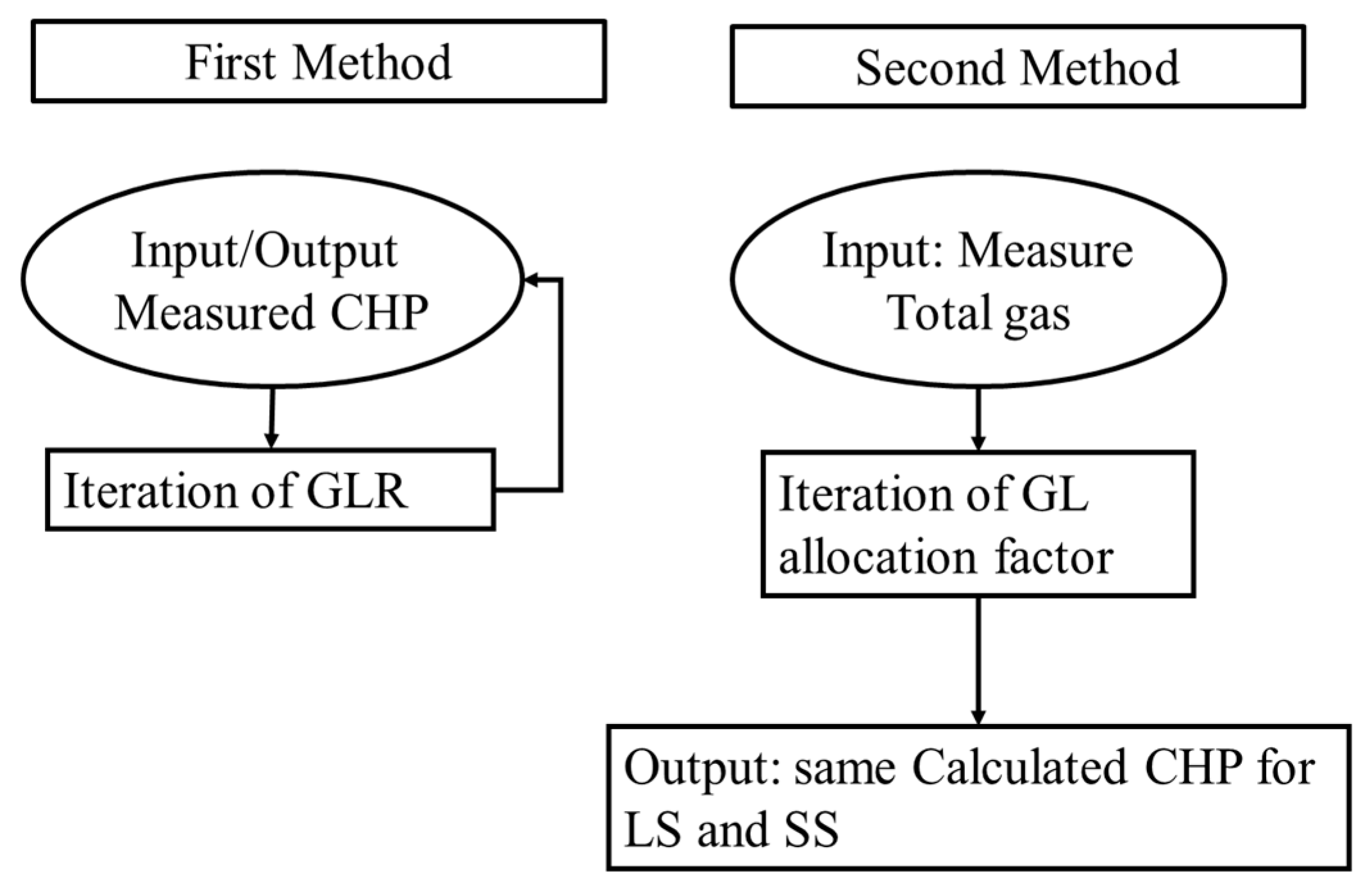
7]. Note that PROSPER does not have the capability of modelling the dual string completion and treat the dual string completion as two separate single string completions. The first method used the measured injection or casing head pressure (CHP) to find the corresponding GLIR. The GLIR is changed, repeatedly, until the CHP estimated by the software matched the measured injection pressure. The workflow required the two strings to be solved independently. The second method uses the measured total GLIR and allocates the lift gas between the two strings assuming the same casing pressure for both of the single wells. This method reiterates the total GLIR allocation ratio as a variable, and a solution is reached when the calculated CHP is the same for both strings. The second method ensures the sum of the GLIR to the LS and SS is equal to the input of the total GLIR.
Figure 2 summarises the workflow for the two methods.
Both of the two methods proposed by PETEX relied on the availability of field measured data. The solution is obtained by an iteration technique. As the software can only model a single well, the solution is obtained without considering the impact of one string on the other. The wells or the strings are considered to flow independently. The interaction of the annulus and the two strings is also ignored. The calculated casing pressure by the software is likely to be the average of the CHP at the surface, as if the LS and SS are flowing as a separate single well. The calculated CHP is almost always lower than the actual measured CHP. The estimation of the gas lift rates to the SS and LS is a mathematical exercise using the iteration technique to match a measured value. No consideration is given to the gas flow phenomenon inside the annulus and tubing.
A study by Chia et al. [
8] noted that for the dual completion gas lift, as both strings share the same common annulus, it is difficult to determine the exact individual GLIR of each string. The researchers suggested to use a pre-known fix value of the gas-oil ratio (GOR) to compute the individual GLIR from the total gas measures at the surface. The assumption of a constant GOR is fallacious as the GOR value changes from time to time. It also required the well to be tested individually, which may not be practical due to operational constraints.
A few researchers have, in more recent years, proposed the use of an artificial intelligence (AI) approach to tackle gas lift optimization. Patterns of changes in operating conditions were identified through the measurement of parameters, and AI algorithms were then applied to correct the conditions. Abbasov et al. proposed a method using machine learning to attain the minimum field measured tubing head pressure oscillation, so as to achieve an optimum production. It relied mainly on field testing and no well modelling is required [
9]. Xiao et al. suggested the use of a calibrated well model to establish the operating envelope for a stable production. An automated workflow is created to monitor, troubleshoot and correct the well for any instabilities during the production [
10]. Both methods are only applicable to single string wells where the wells behave independently of each other.
To obtain an accurate estimate of the gas lift rates for dual string completions, the industry has to resort to a field measurement via a well tracer survey. The tracer method allows the measurement, when both strings are flowing, to account for the interaction between them. However, it is costly and operationally impractical as it requires the mobilization of expensive equipment and personnel. In addition, there is a potential production deferment related to the well work. The well tracer for the dual string can be challenging, as discussed by Abu Bakar et al. [
11]. An average of six hours per survey is required with a 25% rerun for dual strings due to too many points of gas returns.
Hermank et al. proposed the use of distributed thermal sensing (DTS) and distributed acoustic sensing (DAS) for the gas lift surveillance [
12]. The method is less invasive and can provide a precise injection point based on changing temperature and sound signals. However, it would require high capital investment to equip the wells with downhole optical fibers. This method will work well with the single string well but not necessarily with the dual string well. The interpretation of DTS and DAS for the dual string well is a lot more complicated given the pressure and flow dynamics within the annulus as well as between the strings and the annulus.
For an optimum production, the lift gas has to be injected at the correct rate. Excessive or inadequate injected gas can lead to a suboptimal production and flow instability [
13]. So far, the various methods proposed by the researchers do not directly compute the gas lift rates to individual strings for the dual string completion. The solutions were derived by the use of an iterative approach, with simplification (such as an injection at the same depth), averaging, or equating the dual string as two separate single strings. The interactions between the lift gas inside the common annulus and the production fluids in the tubing were not taken into consideration. The results obtained can be misleading as they do not represent the actual operation of a dual string well. Little insight can be derived for gas lift troubleshooting to optimize the lift gas usage.
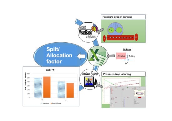
The objective of this study is to develop a hybrid model to determine the gas lift split factor considering the fluids flow phenomena both in the annulus and the tubing. The hybrid model will combine three platforms: the Visual Basic for Application (VBA) programme, PROSPER (a nodal analysis tool) and Excel spreadsheet to compute the gas lift rate into an individual string and subsequently the split factor. The model will be validated using a set of field measured data. This hybrid model allows for an accurate estimation of the lift gas rate for the dual string completion, enabling an efficient use of lift gas and yielding an opportunity for improving the energy efficiency of upstream production facilities.
3. Results and Discussions
3.1. Annulus Pressure Calculation
The pressure calculation is conducted for the annulus via a breakdown into 5 sections, as shown in
Table 1. The diameter calculated here is the equivalent hydraulic diameter. The inlet in the first section is the injection pressure, and the outlet pressure in the last section represents the choke upstream pressure. It is observed that the pressure increases from the point of the inlet down to the orifice depth, for the condition assessed, and there is an estimated increase of 42 psi that accounts for both the hydrostatic and frictional pressure differential. The number of sections is deemed sufficient as the well is vertical in the top sections, and the deviation is only observed in the last two sections.
3.2. Tubing Pressure Calculation
For this study, the best matched PVT correlations were selected. The Standing correlation is used to estimate the GOR, formation volume factor and bubble point pressure. Begg’s correlation is used for the viscosity calculation. For the VLP correlation, PE2 is selected. PE2 is an empirical correlation developed by PETEX, intended to cover a wide range of operating conditions. This correlation uses the flow map by Gould & et al., the Hagedorn Brown correlation for the slug flow and the Duns and Ros for the mist flow. In the transition regime, a combination of slug and mist results is used. It also has improved the VLP calculations for low rates and for the well stability. It provides a more accurate prediction of the minimum load-up rates [
14].
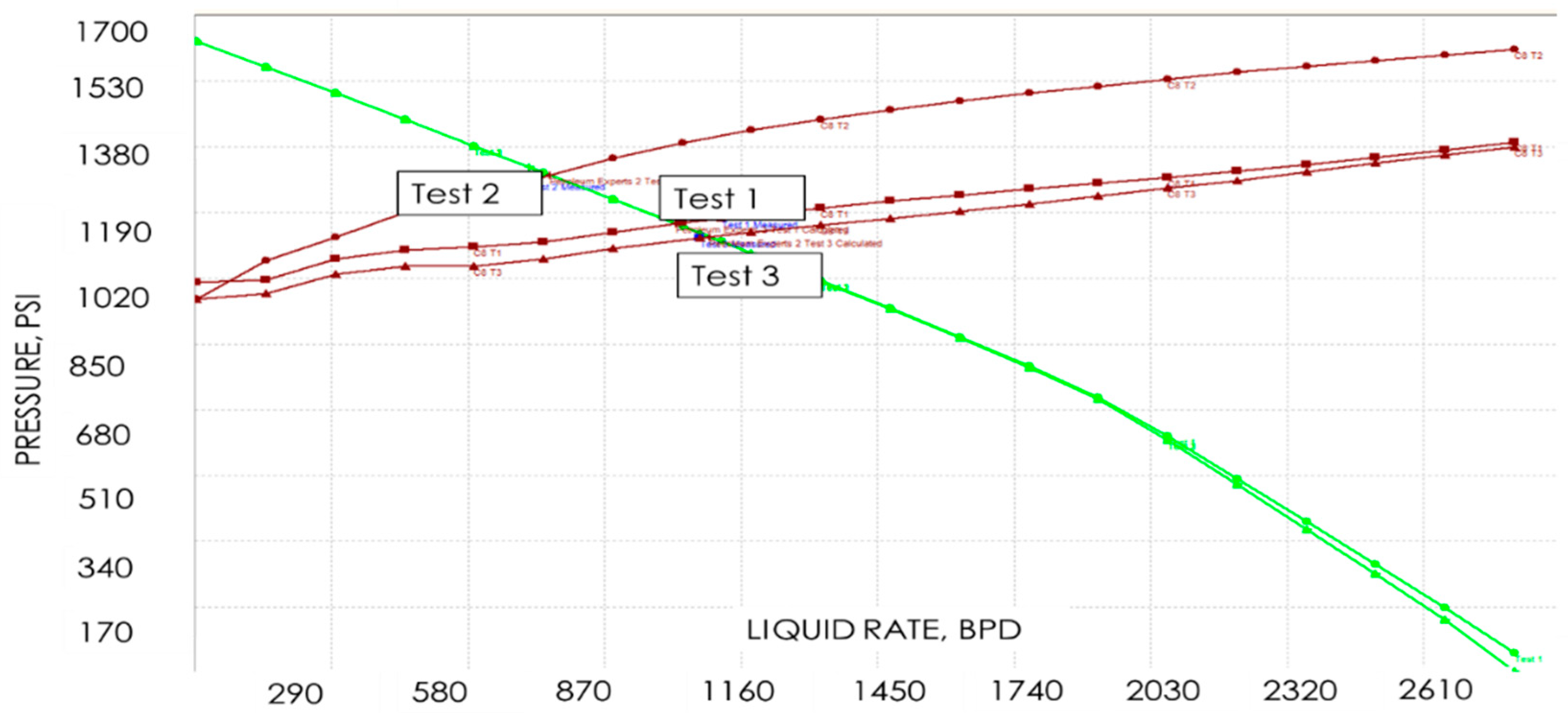
PE2 appeared to have the best match with 3 previous well tests, as shown in
Figure 8. The calculated rate and flowing bottom hole pressure (FBHP) was well within the ±10% of the measured test data. It also has the lowest average absolute error compared to other vertical lift performance correlations. The inflow Performance Relationship (IPR) Model is generated with the Productivity Index (PI) model.
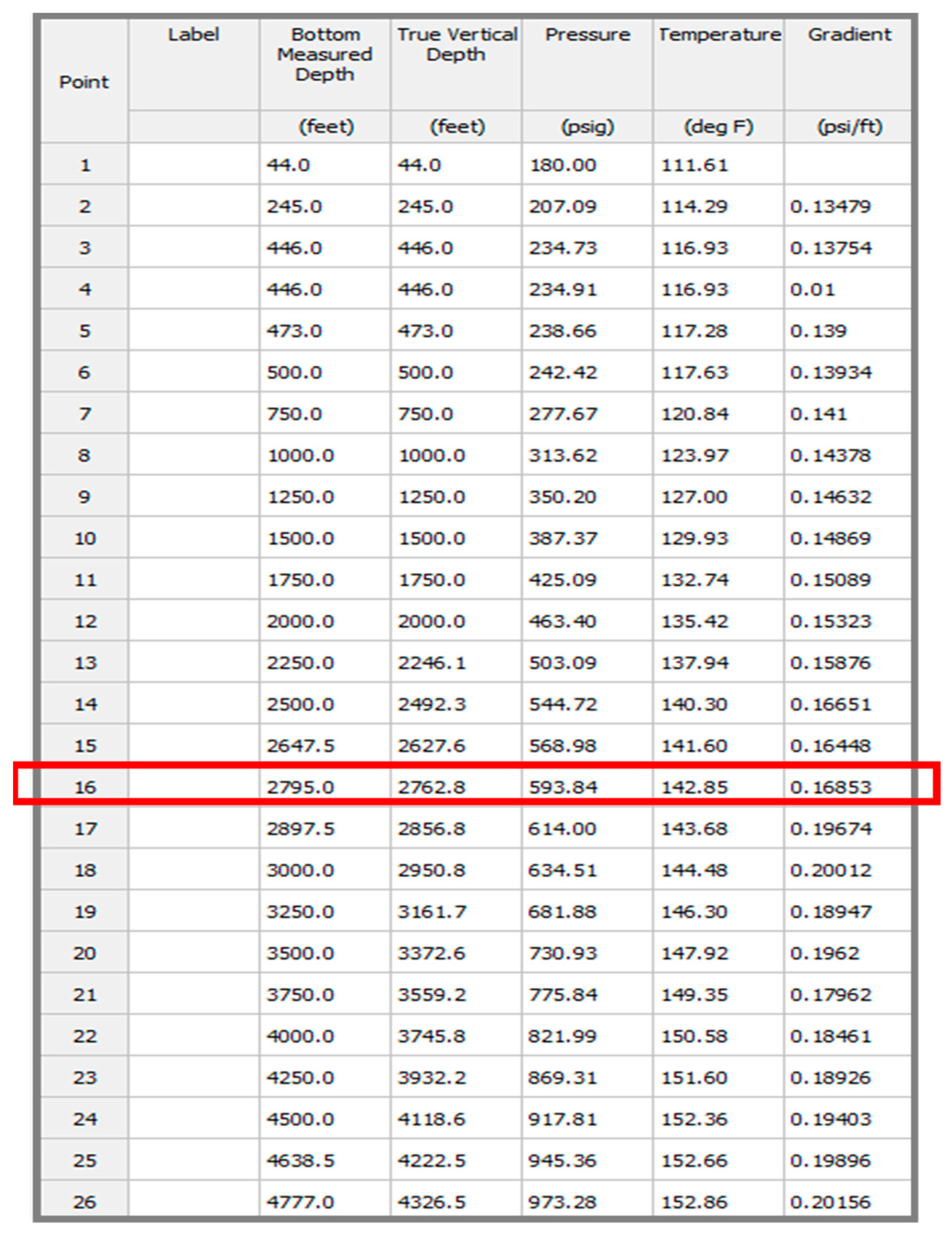
The measured parameters from the well test: the flowing tubing head pressure (FTHP), GOR, and water cut (WC), are the required input for the pressure gradient calculation. The generated pressure profile from the wellhead to the perforation depth can be seen in
Figure 6. The pressure at the orifice is singled out from the depth-pressure profile to represent the downstream orifice pressure (highlighted in
Figure 9).
3.3. Gas Lift Rate (GLIR) Calculation
An example of the gas lift rate calculation is given in
Table 2. The GLIR is obtained via subtracting the SS injection rate from the total gas injected, assuming that all the injections from the surface go into the tubing as per the basis used by both Kamis et al. [
2] and Chia et al [
8]. This also provides a reconciliation to the surface measured gas rate.
3.4. Model Validaton
The split factor is calculated for the two wells, namely, wells “X” and “Y”. Both wells are dual string completion type wells, with 3½ inch production tubing and a low angle deviation angle. A wide range is observed in the measured GOR and WC for the wells. “X” SS and LS and “Y” LS are producing from the deeper reservoir, with a water breakthrough and high GOR due to depletion. “Y” SS produced from the shallower reservoir with a low water cut and is still above its bubble point, which explains the noticeable lower GOR.
A comparison between the calculated values from the model and measured date from the field is given in
Table 3.
The model demonstrated that it can estimate the lift gas distributions for both well “X” and well “Y”, over a considerable range of operating conditions, to an average relative error of between 2% and 7 %, as shown in
Table 3. The higher discrepancy in well “Y” is possibly due to poor matching between the well test data and the calculated PROSPER results. This could be due to inaccuracies in the measurement data collected during the well test, discrepancies in the PROSPER modelling of the actual well conditions, or both. The collected well test data were within the acceptable accuracies. For well “Y”, during the tracer survey, it was observed that multi-pointing had occurred at the LS. The PROSPER model has assumed a single injection point for LS (well “Y”). It could not mimic the multi-pointing actual conditions, hence the poor match between the measured well test data and the simulated results.
3.5. Case Studies
The proposed hybrid model is used to generate the lift gas distribution and compared to the available field well test data for well “X”, see
Table 4. The field well test data were based on PETEX methods, assuming the dual strings as a single well model, as described previously in
Section 1.
There is a tendency to under-allocate the lift gas for SS, overlooking gas robbing phenomena. The well test data 1 was off by 80 Mscf/D, whilst the well test data 2 was off by almost 185 Mscf/D. The calculated split ratios from the proposed hybrid model in both tests are closer to the Well Tracer measured data, indicating a higher consistency and better accuracy. This is in line with the understanding that the single well models, such as those proposed by PETEX, are limited for application due to the interaction of the gas distribution between the 2 strings.
Having an accurate GLIR estimation is fundamental to the optimization of the gas lift to improve the production and hence the profitability of the well. The potential impact of an accurate GLIR estimate on the productions from well “X” can be demonstrated by
Figure 10, and
Table 5 and
Table 6.
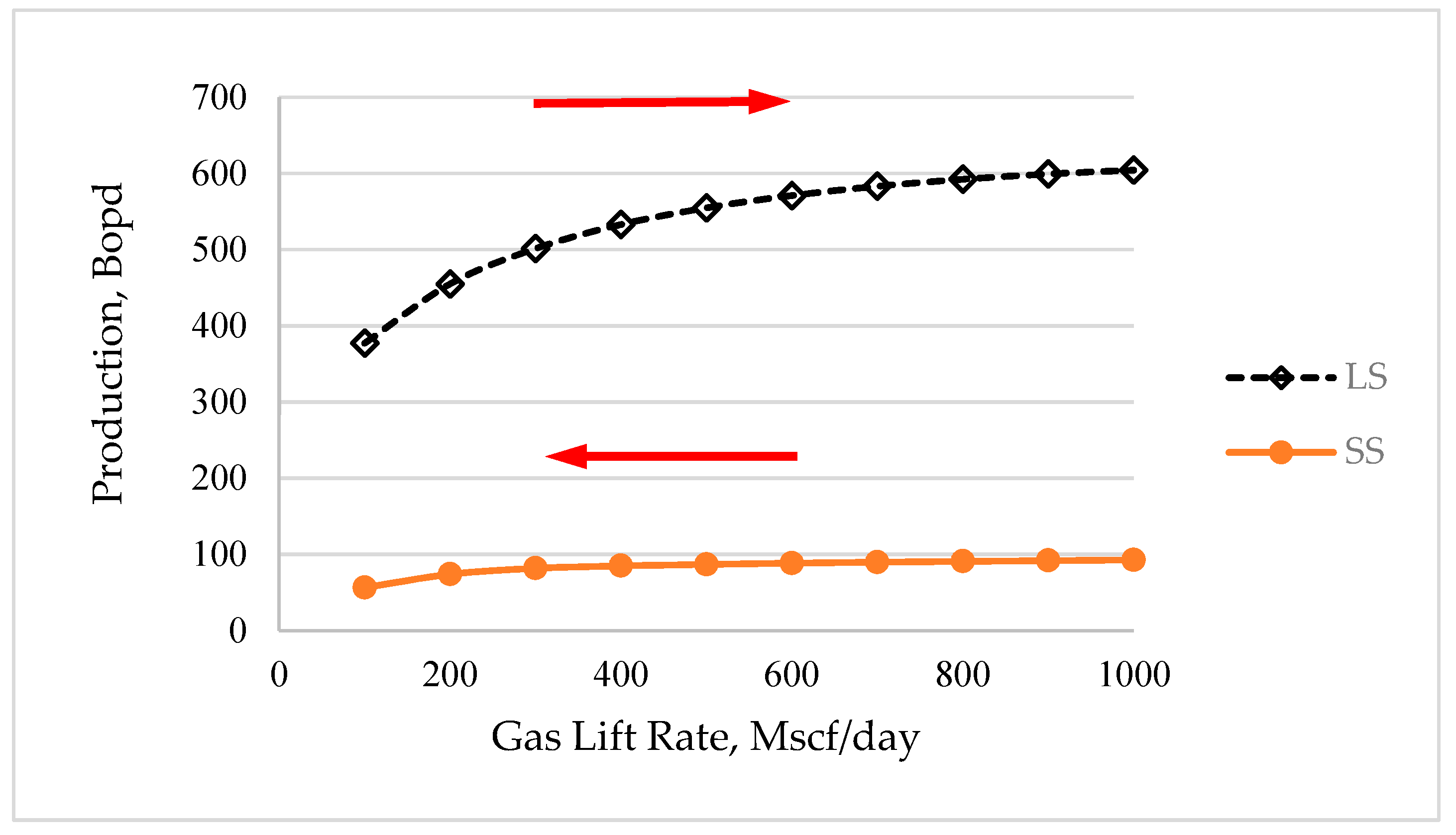
Figure 10 showed that the production for LS is more sensitive to gas lift rate changes. The red arrow indicates the directional changes on the GLIR redistribution for SS and LS to achieve a production optimization. Reducing the GLIR for SS by 200 Mscf/D merely cut back the production by 5 Bopd, whilst increasing the same amount will increase the production by almost 50 Bopd for LS. This is because LS is producing from a better productivity index (PI) reservoir and the water cut is also higher at 80%, resulting in the requirement for more gas to lift the total liquid. On the other hand, SS, due to a low water cut and relatively lower liquid rate, is nearing it optimum operating condition. There is an opportunity to reduce the gas lift rate for the SS and redistribute to LS to improve the production as a whole.
The variation of the production with the lift gas rate is tabulated in
Table 5.
The GLIR can be varied by changing the orifice sizes. The proposed hybrid model is used to generate the split ratio between the LS and SS for the selected 3 different orifice sizes, as shown in
Table 6.
The existing orifice for SS is 12/64th. By reducing the orifice size for the SS to 10/64 in. and 8/64 in., the GLIR is cut back by 128 and 262 Mscf/D respectively. This saving in the GLIR from the SS may be re-allocated to LS or other wells in the field to enhance production. An estimated 48 Bopd gain can be achieved by reducing the orifice size for the SS from 12/64 in. to 8/64 in. based on the gas lift performance curve of LS and SS.
3.6. Features, Advantages and Limitations of the Proposed Hybrid Model
The model is able to determine the lift gas rate for the individual string, via a combination usage of VBA, the available nodal analysis tool (PROSPER) and proven empirical correlations. This sets it apart from the existing practices of conducting multiple iterations to yield a mathematical solution without considering actual conditions of the dual string gas lift operation. Another advantage of the model is that it only requires surface measured parameters which can be obtained easily with high accuracy. The inputs required are the injection pressure for the casing pressure calculation and the well test parameters (GOR, FTHP, liquid rates and WC) for the tubing pressure computation. This approach provides a simplification to the calculation process.
An accurate estimate of the GLIR is fundamental to the production optimization of gas-lifted wells. This is especially crucial for dual string completion type oil producers. The application of the model for the gas lift optimization of dual string wells is demonstrated in
Section 3.5., where a saving of 262 Mscf/d GLIR from SS is used to increase the production from LS by 48 Bpod. This can be extended to other dual string wells within the same field. Injecting just the right amount of gas lift for the desired production is the principle concern for operators of mature fields where the amount of gas lift available is often constrained by the existing facility system, the lift gas compressors [
26]. The opportunities to enhance the production can also be realized through the optimizing of parameters such as the casing head pressure, injection depth and orifice size.
The model is developed for steady state, continuous injection conditions, which are commonly fulfilled in oil production following the unloading operations, when and where only the deepest gas lift valve is operating. It does not cater to transient operations such as those during well unloading or an unstable injection resulting from the flow instability of the production conditions. Nor does the model apply to multi-pointing, conditions whereby the lift gas enters the tubing through more than one point along the tubing. This could be due to poor design or unintentional changes in the operating condition. Under such circumstances, a transient analysis tool or field measurement may be more suitable for diagnostic purposes.
The proposed model offers a better method to quantify the gas lift split factor, thereby enabling the efficient use of gas lift, paving a way for the improvement on gas lift optimization in dual string completion and for opportunities to understand the overall produced gas usage. This would inevitably improve the energy efficiency of upstream oil production facilities.
The model can be adapted easily into the current industry gas lift optimization work flow. Lastly, the proposed hybrid model provides a potential substitute to the Well Tracer measurement method, averting the costs and risks of well intervention.


