Abstract
Thermal energy storage (TES) is an essential part of a solar thermal/hot water system. It was shown that TES significantly enhances the efficiency and cost effectiveness of solar thermal systems by fulfilling the gap/mismatch between the solar radiation supply during the day and peak demand/load when sun is not available. In the present paper, a three-dimensional numerical model of a water-based thermal storage tank to provide domestic hot water demand is conducted. Phase change material (PCM) was used in the tank as a thermal storage medium and was connected to a photovoltaic thermal collector. The present paper shows the effectiveness of utilizing PCMs in a commercial 30-gallon domestic hot water tank used in buildings. The storage efficiency and the outlet water temperature were predicted to evaluate the storage system performance for different charging flow rates and different numbers of families demands. The results revealed that increases in the hot water supply coming from the solar collector caused increases in the outlet water temperature during the discharge period for one family demand. In such a case, it was observed that the storage efficiency was relatively low. Due to low demand (only one family), the PCMs were not completely crystallized at the end of the discharge period. The results showed that the increases in the family’s demand improve the thermal storage efficiency due to the increases in the portion of the energy that is recovered during the nighttime.
1. Introduction
Phase change materials (PCMs) are an important topic in research and industry. Due to the intermittent supply characteristics of solar energy, energy storage represents a potential solution by storing the energy during the daytime to use it during the nighttime. PCMs can store large amounts of heat at constant temperature while the material changes phase or state. When PCMs are coupled with solar technology, efficiency of traditional heating, ventilation, and air conditioning (HVAC) systems may potentially increase. The majority of applications for PCMs are for space heating/cooling and providing domestic hot water for buildings. Also, PCMs have high energy density and latent heat, and they are cost-effective. There are several applications in which PCMs were implemented as shown in Table 1.
Table 1.
Phase change material (PCM) applications.
Phase change material (PCM) is an environmentally friendly material used to improve building energy consumption and indoor thermal comfort [1,2].
An experimental study investigated a heat pump utilizing a thermal energy storage (TES) tank [3]. In their research, it was found that a PCM storage tank has 14.5% better performance. Moreover, the PCM storage tank improved indoor temperature stability within comfort 20.65% longer in time compared to the conventional water tank. Also, a thermal storage system was installed in a one family house [4], where sodium acetate trihydrate (SAT) was used as a PCM.
The performance of thermal storage systems was analyzed [25]. A south-oriented wall was used as thermal storage with phase change materials embedded in the wall. The thermal storage system can store solar radiation up to 6–8 h after solar irradiation; this has effects on the stability of the daily temperature swings (up to 10 °C).
Zalba et al. [26] conducted an experimental study to store outdoor cold during nighttime and to release it indoors during daytime using PCMs. The results revealed that the system was successfully tested for 1000 cycles without any degradation in the performance of the system.
Kenneth [27] developed a solar system that utilizes a PCM in domestic houses in the United Kingdom (UK). The system consisted of solar flat plate collectors, which put the energy into a storage tank and PCM-filled panels. Calcium chloride was used as the PCM with a melting point of 29 °C. The results revealed that the use of PCMs reduced energy consumption by 18–32%.
The literature shows a limited number of investigations on PCM thermal storage tanks coupled with a solar thermal collector to provide domestic hot water or building heating. In the present paper, a numerical model was developed for a 30-gallon hot water tank utilizing n-eicosane PCM as the thermal store medium. The solar energy was used to charge the storage tank during the daytime (9 h) and then the thermal energy was recovered to provide hot domestic water during the discharge period (15 h).
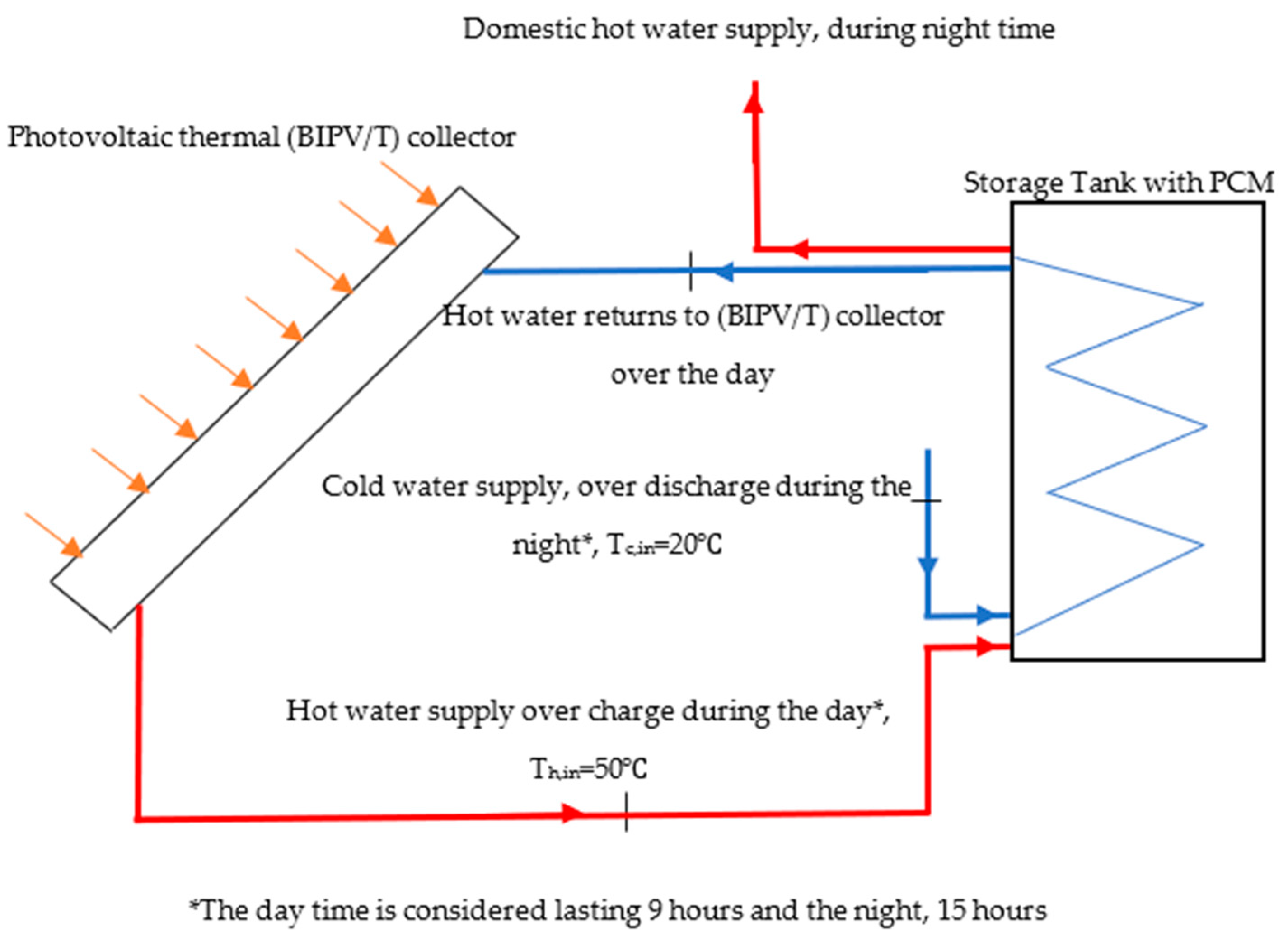
2. Numerical Model Description
In this study, a three-dimensional numerical model was created using finite element techniques (COMSOL Multiphysics) for a 30-gallon domestic hot water thermal storage tank connected to a photovoltaic thermal collector. The tank height and diameter were 1.15 m and 0.46 m, respectively, as shown in Figure 1. PCMs are present in small cylindrical containers inside the tank as shown in Figure 2a. The tank contains a spiral heat exchanger to exchange the heat from the circulating water to the thermal storage medium as shown in Figure 2b. The diameter of the heat exchanger pipe was 0.02 m, and the length of the heat exchanger was 1.1 m with a spiral diameter of 0.28 m. The length and diameter of the PCM containers were 0.2 m and 0.05 m, respectively. The tank consisted of 32 PCM cylindrical containers per row with a total of five rows. The properties of the PCM used in the model are presented in Table 2.
Figure 1.
System schematic diagram.
Figure 2.
Numerical model description.
Table 2.
PCM properties.
2.1. Governing Equations
The assumptions on which the governing equations were based prior to the formulation of the model were as follows:
- (1)
- The fluid flow is Newtonian and incompressible;
- (2)
- No heat is generated inside tank solid domains;
- (3)
- The variation of thermo-physical properties of the PCM can be neglected.
When these assumptions were taken into consideration, a system of governing equations to describe the heat transfer and fluid flow were solved and coupled. In the present study, an attempt was made to solve the Navier–Stokes equations for the fluid flow through the internal spiral heat exchanger and a free convection fluid flow inside the tank. In addition, the energy equations for all domains including the tank solid domain, the PCM domain, and the fluid domain were solved. It is important to note that the Navier–Stokes equations and the energy equations were coupled. The coupling was established for each time step using the velocity field obtained from Navier–Stokes equations as an input to evaluate the convective heat transfer term in the energy equation.
The Navier–Stokes equation and the energy equation were solved numerically using COMSOL Multiphysics [3] as follows:
Momentum equation along x-direction:
Momentum equation along y-direction:
Momentum equation along z-direction:
The continuity equation for this simulation can be expressed as
The energy equation was as follows:
where represents the water density, cp represents the fluid specific heat, p represents the pressure, u, v, and w represent the coordinates of a velocity field vector, T represents the temperature, represents the dynamic viscosity of the fluid, and K represents the thermal conductivity.
For the phase change material,
where represents the PCM solid fraction, L represents the latent heat of the phase change material, phases 1 and 2 represent the solid and liquid phases, respectively, and represents the melting fraction per degree of temperature.
2.2. Boundary Conditions
Boundary conditions can be divided into two types: heat transfer boundary conditions and fluid flow boundary conditions. The thermal boundary conditions involve the inlet water temperature to the heat exchange, which was 50 °C during the charging period over the daytime (9 h) and 20 °C during the discharge period over the nighttime (15 h). Moreover, the thermal boundary conditions included the insulated wall of the tank outer surface (∇.T = 0).
The fluid flow boundary conditions included the inlet velocity (U) at the inlet portion (assuming a flat profile), with no pressure constraints at the outlet portion and walls (e.g., no slip condition) at the remainder of the surface (see Figure 2a). It is important to note that, in the present study, the flow rates during the charging period were set to 2 L/m, 3 L/m, and 4 L/m. In addition, the flow rate of the demand of hot water during the discharge period was set to match the typical hot water demand for one, two, three, and four families, as shown in Figure 3 [28]. A typical family consists of two adults and two children [28]. As shown in Figure 3, the demand was low over the first 5 h of the day and increased dramatically over the rest of the day.
Figure 3.
Typical domestic hot water demand for different numbers of families.
3. Results and Discussion
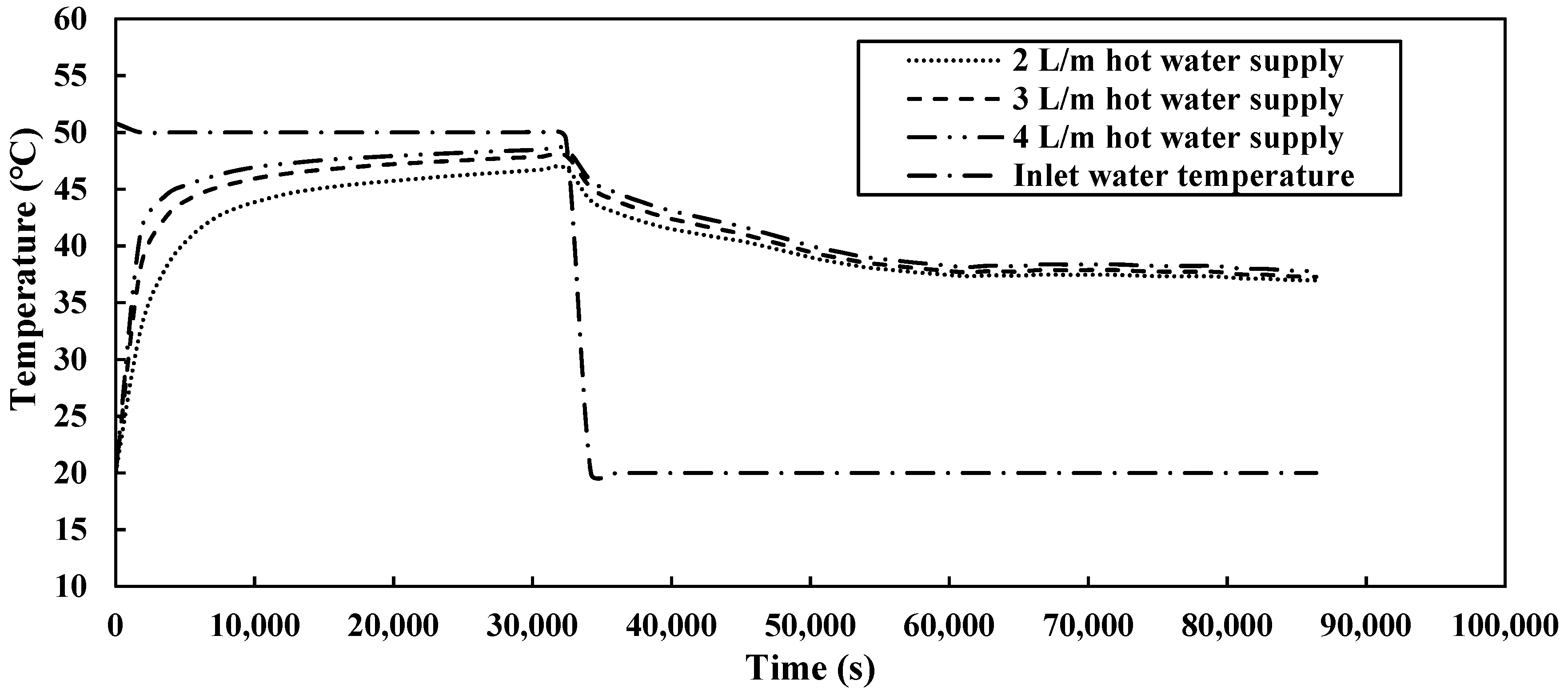
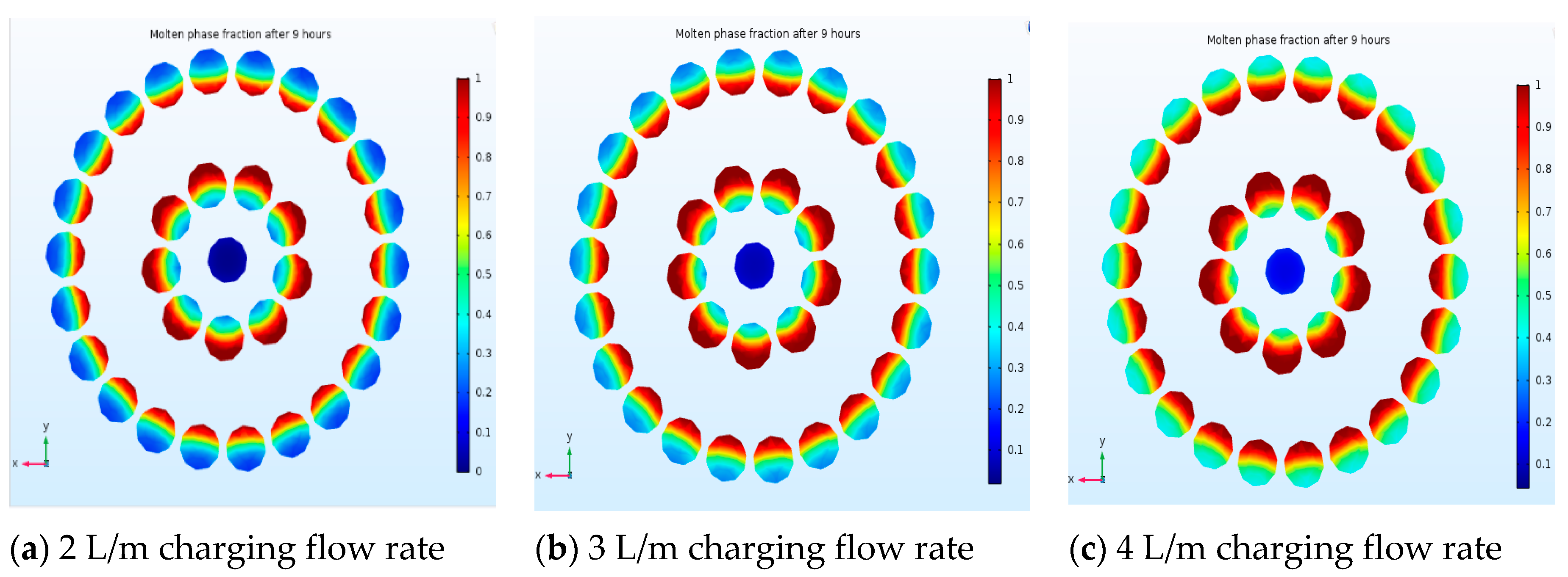
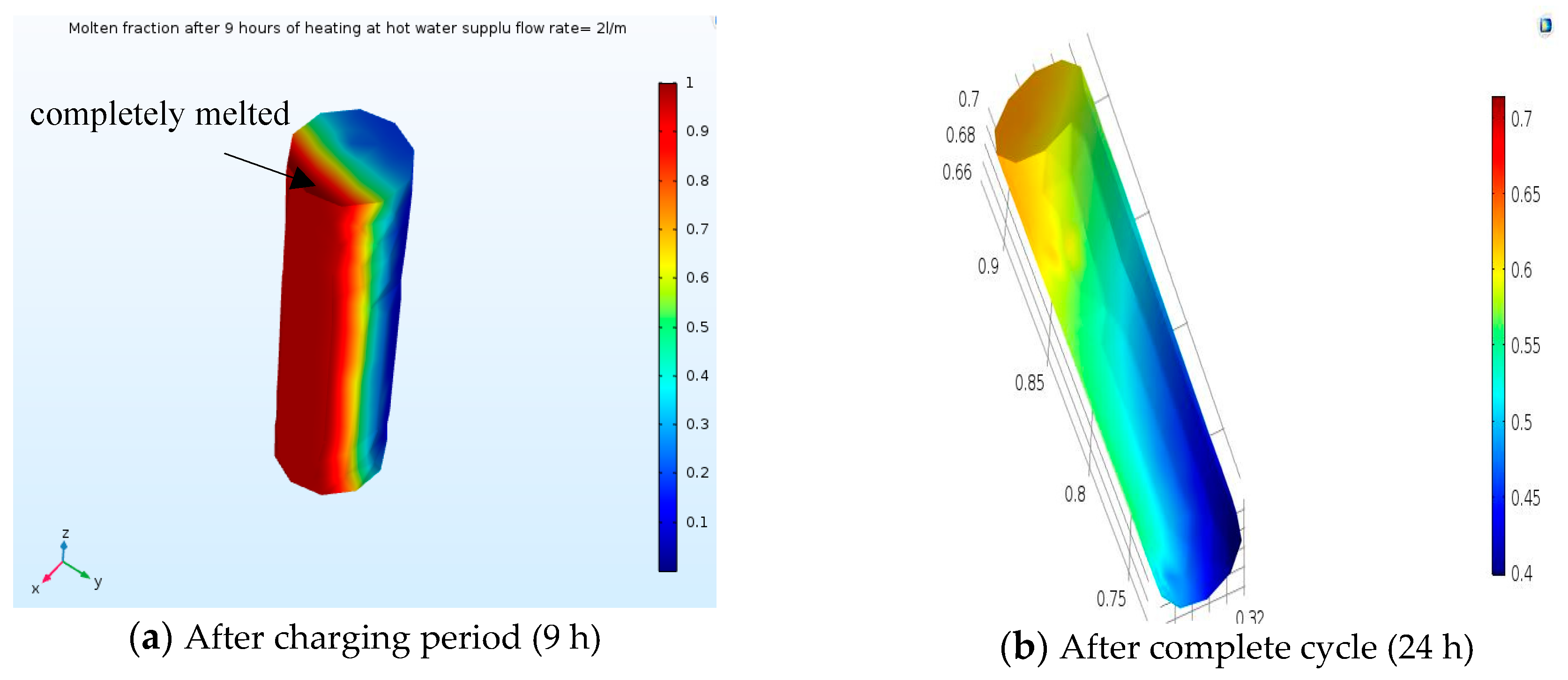
3.1. Effect of Charging Flow Rates
In this section, the flow rates over the charging period (9 h) were set to 2 L/m, 3 L/m, and 4 L/m. The demand of domestic hot water flow rate over the discharge period (during the remaining 15 h) was fixed to match the typical hot water demand for one family, as illustrated in Figure 3. Figure 4 shows the storage tank inlet and outlet temperatures versus time.
Figure 4.
Storage tank inlet and outlet water temperatures.
As shown in Figure 4, the inlet temperature was 50 °C during the charging period (9 h), which came from the photovoltaic thermal (BIPVT/T) collector. Then, the inlet water temperature decreased to 20 °C during the discharge period. The amount of thermal energy was calculated as follows:
It was noted that, over the charging period, the amount of heat stored () increased upon increasing the hot water supply flow rate at given demand.
As a result, the average outlet water temperatures during the discharge period increased with the increase in the hot water flow rate during the 9-h charging period, as shown in Figure 4.
Table 3 shows the amount of heat being stored and extracted during charging and discharging periods, respectively. It was observed that the maximum storage efficiency was 39%. The thermal storage efficiency is defined as a ratio between the energy extracted and the energy injected into the tank. This means that only 35–39% of stored energy was successfully extracted during the discharge period. Figure 5 and Figure 6 explain the reason for such low storage efficiency. Figure 5 shows the melting fraction of the PCM cylinders; when it is equal to one, it means that the PCMs are completely melted. As shown in this figure, PCMs were not melted completely after the 9-h charging period. This means that there was a capability of the storage tank to absorb more heat during the charging period.
Table 3.
Tank storage efficiency.
Figure 5.
Melting fraction of phase change material (PCM) after charging period (9 h).
Figure 6.
Melting fraction of phase change material after discharge period (24 h).
Moreover, Figure 6 shows that the PCMs were not solidified/frozen completely after the discharge period (24 h). It was observed that about 50% of PCMs were not completely solidified/frozen. This means that the tank still had some available heat to be used. To reach better efficiency, the hot water demand should be increased in order to absorb the remaining stored heat, allowing the PCM to be completely solidified/frozen.
In order to better understand the melting phenomenon, Figure 7 shows the melting fraction of a single PCM cylinder. As shown in this figure, around half of the cylinder was melted completely after the charging period. Moreover, after completing one cycle (e.g., 24 h), the PCM cylinder still had a liquid phase up to 0.7, as shown in Figure 7b.
Figure 7.
Melting fraction over charging and discharging periods for a single PCM cylinder.
Figure 8a shows the mid-plane temperature contours at the end of charging period. As shown in this figure, the temperature of the circulating water coming from the solar collector was about 50 °C, and the average temperature of the tank was about 34 °C. Also, Figure 8b shows the temperature contours after 24 h, where the average temperature was about 30 °C.
Figure 8.
Mid-plane temperature contours after charging and discharging periods.
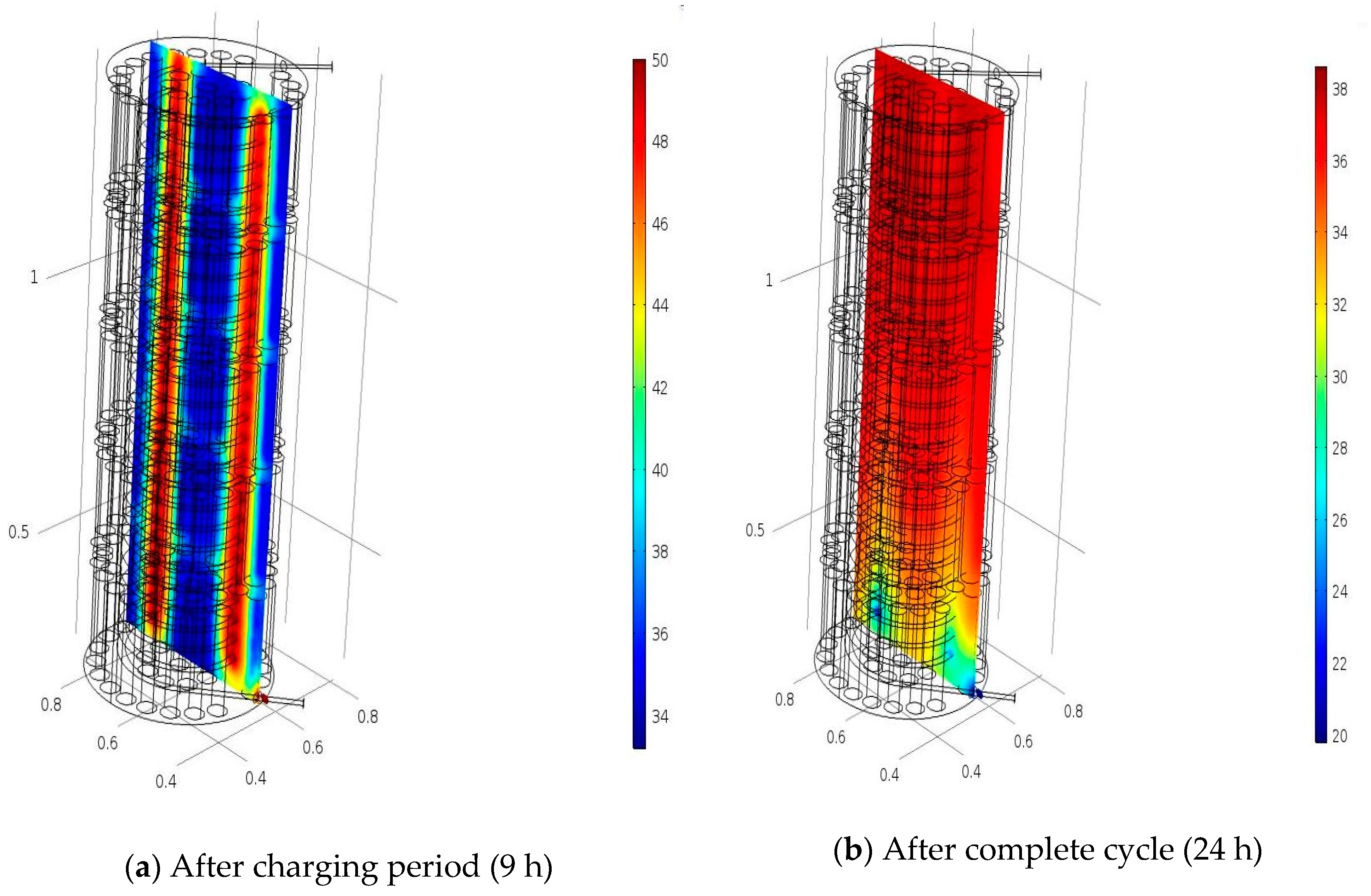
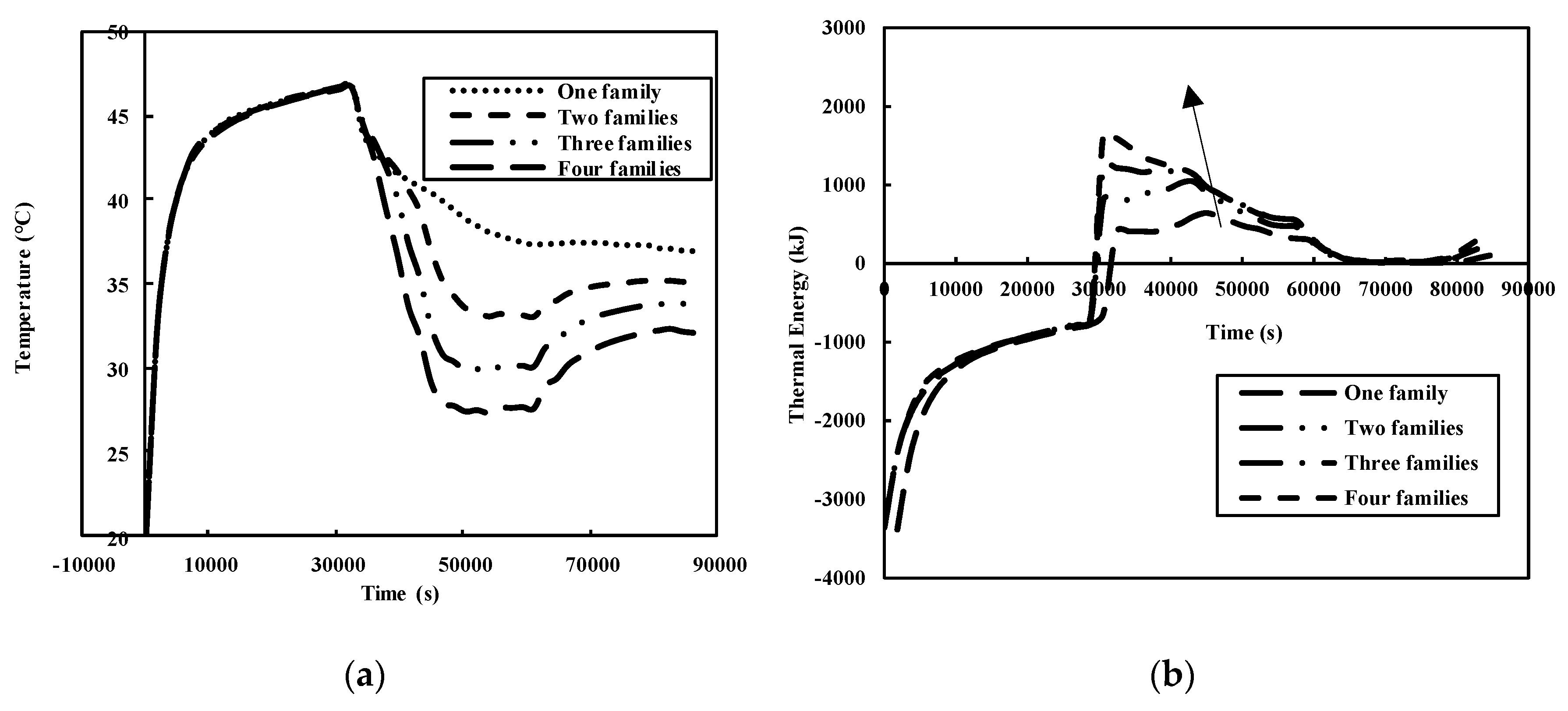
3.2. Effect of Number of Families
In order to enhance the storage efficiency, domestic hot water demand was increased to match the typical demand of two, three, and four families. Figure 9a shows the outlet temperatures from the tank versus time for the demand of one, two, three, and four families and 2 L/m of hot water supply during the charging period. It was noted that the outlet temperature decreased with the increase in the number of families. The increase in hot water demand during the discharge periods (number of families) meant increases in the thermal energy to be extracted/recovered from the thermal storage tank, as shown in Figure 9b. However, for the demand of four families, it was observed that the domestic hot water temperature over the discharge period decreased dramatically until it reached below 30 °C. In such a case, a supplement back-up system is needed to maintain the outlet domestic water above 30 °C.
Figure 9.
Outlet water temperatures and thermal energy over one day of operation. (a) Outlet temperature variation versus number of families; (b) Thermal energy stored and recovered during the day for the demands of one, two, three, and four families.
In order to quantify the thermal storage efficiency, Table 4 shows the amount of heat that was injected into the thermal storage tank during the charging period (9 h) and the amount of heat that was absorbed/recovered during the discharge periods. It was observed that, for a given hot water supply, increasing the number of families increased the efficiency from 35% for one family to 82% for four families. The four families used the whole store of energy and, because of the high demand rate, a big portion of the stored energy was recovered. As a result, the storage efficiency was increased up to 82%.
Table 4.
Thermal storage efficiencies for multiple families.
4. Conclusions
This paper presented a CFD numerical code of a domestic hot water tank utilizing a phase change material as a storage medium. The following conclusions were made:
- The increases in the hot water supply during the charging periods increased the storage efficiency from 35% to 39%.
- At given hot water supply, increasing the number of families increased the efficiency from 35% for one family to 82% for four families.
- At given hot water supply, the heat extracted over the nighttime increased from 7869 kJ to 18,288.89 kJ upon increasing the demand from one family to four families.
Further developments and future work on the present topic involve the introduction of nanofluid to enhance the thermal storage efficiency of the tank, the use of different PCMs and melting temperatures, and the calculation of the electricity consumption to determine the energy efficiency. Moreover, the effect of inlet water profile (cycling temperature) will be investigated as an extension of the present work.
Author Contributions
Conceptualization, methodology, validation, and original draft preparation, A.B.; review and editing, S.D. and Z.S.
Funding
This research was funded by Natural Sciences and Engineering Research (NSERC).
Acknowledgments
The authors acknowledge the full financial support of the National Science and Engineering Research Council (NSERC) and Ecologix Heating Technologies Inc.
Conflicts of Interest
The authors declare no conflict of interest
References
- Baetens, R.; Jelle, B.; Gustavsen, A. Phase change materials for building applications: A state-of-the-art review. Energy Build. 2010, 42, 1361–1368. [Google Scholar] [CrossRef]
- Lin, W. Development and evaluation of a ceiling ventilation system enhanced by solar photovoltaic thermal collectors and phase change materials. Energy Convers. Manag. 2014, 88, 218–230. [Google Scholar] [CrossRef]
- Moreno, P. PCM thermal energy storage tanks in heat pump system for space cooling. Energy Build. 2014, 82, 399–405. [Google Scholar] [CrossRef]
- Johansen, J. Laboratory Testing of Solar Combi System with Compact Long Term PCM Heat Storage. Energy Procedia 2016, 91, 330–337. [Google Scholar] [CrossRef]
- Enibe, S. Performance of a natural circulation solar air heating system with phase change material energy storage. Renew. Energy 2002, 27, 69–86. [Google Scholar] [CrossRef]
- Enibe, S. Parametric effects on the performance of a passive solar air heater with storage. In Proceedings of the World Renewable Energy Congress WII, Cologne, Germany, 19–26 October 2002. [Google Scholar]
- Buddhi, D.; Sahoo, L. Solar cooker with latent heat storage: Design and experimental testing. Energy Convers. Manag. 1997, 38, 493–498. [Google Scholar] [CrossRef]
- Mehling, H.; Cabeza, L.; Hippel, S.; Hiebler, S. Improvement of stratified hot water heat stores using a PCMmodule. In Proceedings of the EuroSun, Bologna, Italy, 23–26 June 2002. [Google Scholar]
- Mehling, H. PCM-module to improve hot water heat stores with stratification. Renew. Energy 2003, 28, 699–711. [Google Scholar] [CrossRef]
- Safarik, M.; Gramlich, K.; Schammler, G. Solar absorption cooling system with 90 _C-latent heat storage. In Proceedings of the World Renewable Energy Congress WII, Cologne, Germany, 19–26 October 2002. [Google Scholar]
- Buick, T.; O’Callaghan, P.; Probert, S. Short-term thermal energy storage as a means of reducing the heat pump capacity required for domestic central heating systems. Int. J. Energy Res. 1987, 11, 583–592. [Google Scholar] [CrossRef]
- Charters, W.L.; Aye, L.; Chaichana, C.; MacDonald, R. Phase change storage systems for enhanced heat pump performance. In Proceedings of the 20th International Congress of Refrigeration, IIR/IIF, Sydney, Australia, 16–17 June 1999. [Google Scholar]
- Lorsch, H. Improving Thermal and Flow Properties of Chilled Water. Part 2: Facility Construction and Flow Tests; American Society of Heating, Refrigerating and Air-Conditioning Engineers, Inc.: Atlanta, GA, USA, 1997. [Google Scholar]
- Velraj, R.; Anbudurai, K.; Nallusamy, N.; Cheralathan, M. PCM based thermal storage system for building airconditioning––Tidal Park, Chennai. In Proceedings of the World Renewable Energy Congress WII, Cologne, Germany, 29 June–5 July 2002. [Google Scholar]
- Ismail, K. Ice-Banks: Fundamentals and Modelling; State University of Campinas: Campinas-SP-Brazil, Brazil, 1998. [Google Scholar]
- Hasnain, S. Review on sustainable thermal energy storage technologies, Part II: Cool themal storage. Energy Convers. Mgmt. 1998, 39, 1139–1153. [Google Scholar] [CrossRef]
- Bl€uher, P. Latent€wärmespeicher erh€oht den Fahrkomfort und die Fahrsicherheit. ATZ Automob. Z. 1911, 93, 3–8. [Google Scholar]
- Hunold, D.; Ratzesberger, R.; Tamme, R. Heat transfer measurements in alkali metal nitrates used for PCM storage applications. In Proceedings of the Eurotherm Seminar No. 30, Hamburg, Germany, 27 February–1 March 1992. [Google Scholar]
- Hunold, D.; Ratzesberger, R.; Tamme, R. Heat transfer mechanism in latent-heat thermal energy storage medium temperature application. In Proceedings of the 6th International Symposium on Solar Thermal Concentrating Technologies, Mojacar, Spain, 28 September–2 October 1992. [Google Scholar]
- Michels, H.; Hahne, E. Cascaded latent heat storage for solar thermal power stations. In Proceedings of the Eurosun, Freiburg, Germany, 16–19 September 1996. [Google Scholar]
- Michels, H.; Pitz-Paal, R. Cascaded latent heat storage for parabolic trough solar power plants. Sol. Energy 2007, 81, 829–837. [Google Scholar] [CrossRef]
- Vasiliev, L. Latent heat storage modules for preheating internal combustion engines: Application to a bus petrol engine. Appl. Therm. Eng. 2000, 20, 913–923. [Google Scholar] [CrossRef]
- Cabeza, L.; Roca, J.; Nogu_es, M.; Zalba, B.; Mar, J. Transportation and conservation of temperature sensitive materials with phase change materials: State of the art. In Proceedings of the IEA ECES IA Annex 17 2nd Workshop, Ljubljana, Slovenia, 3–5 April 2002. [Google Scholar]
- Mulligan, J.; Colvin, D.; Bryant, Y. Microencapsulated phase-change material suspensions for heat transfer in spacecraft thermal systems. J. Spacecr. Rocket. 1996, 33, 278–284. [Google Scholar] [CrossRef]
- Guarino, F. PCM thermal storage design in buildings: Experimental studies and applications to solaria in cold climates. Appl. Energy 2017, 185, 95–106. [Google Scholar] [CrossRef]
- Zalba, B. Free-cooling of buildings with phase change materials. Int. J. Refrig. 2004, 27, 839–849. [Google Scholar] [CrossRef]
- Kenneth, I.P. Solar Thermal Storage Using Phase Change Material for Space Heating of Residential Buildings; Research Article on Net; University of Brighton, School of the Environment: Brighton, UK, 2002. [Google Scholar]
- American Society of Heating, Refrigerating and Air-Conditioning Engineers. ASHRAE Applications Handbook, I-P and SI edn; American Society of Heating, Refrigerating, and Air-Conditioning Engineers, Inc.: Atlanta, GA, USA, 2003. [Google Scholar]
© 2019 by the authors. Licensee MDPI, Basel, Switzerland. This article is an open access article distributed under the terms and conditions of the Creative Commons Attribution (CC BY) license (http://creativecommons.org/licenses/by/4.0/).