Review

Enabling Large-Scale Carbon Capture, Utilisation, and Storage (CCUS) Using Offshore Carbon Dioxide (CO2) Infrastructure Developments—A Review

1
Research Council of Norway, PO Box 564, 1327 Lysaker, Norway
2
U.S. Department of the Interior, Bureau of Ocean Energy Management, Sterling, VA 20166, USA
3
IEA Greenhouse Gas R&D Programme, Pure Offices, Cheltenham Office Park, Hatherley Lane, Cheltenham Glos. GL51 6SH, UK
4
Aker Solutions, Norway, PO Box 94, 1325 Lysaker, Norway
5
Department of Physics and Technology, University of Bergen, 5020 Bergen, Norway
6
Equinor, 7005 Trondheim, Norway
7
Jackson School of Geosciences, University of Texas at Austin, Box X, Austin, TX 78713, USA
8
Petrobras, Rio de Janeiro 20031-912, Brazil
*
Author to whom correspondence should be addressed.
Energies 2019, 12(10), 1945; https://doi.org/10.3390/en12101945
Submission received: 8 April 2019 / Revised: 26 April 2019 / Accepted: 14 May 2019 / Published: 21 May 2019
(This article belongs to the Special Issue CO2 EOR and CO2 Storage in Oil Reservoirs)

Abstract

:
Presently, the only offshore project for enhanced oil recovery using carbon dioxide, known as CO2-EOR, is in Brazil. Several desk studies have been undertaken, without any projects being implemented. The objective of this review is to investigate barriers to the implementation of large-scale offshore CO2-EOR projects, to identify recent technology developments, and to suggest non-technological incentives that may enable implementation. We examine differences between onshore and offshore CO2-EOR, emerging technologies that could enable projects, as well as approaches and regulatory requirements that may help overcome barriers. Our review shows that there are few, if any, technical barriers to offshore CO2-EOR. However, there are many other barriers to the implementation of offshore CO2-EOR, including: High investment and operation costs, uncertainties about reservoir performance, limited access of CO2 supply, lack of business models, and uncertainties about regulations. This review describes recent technology developments that may remove such barriers and concludes with recommendations for overcoming non-technical barriers. The review is based on a report by the Carbon Sequestration Leadership Forum (CSLF).

1. Introduction

Enhanced oil recovery (EOR) using carbon dioxide (CO2), known as CO2-EOR, has a dual purpose: (1) To recover additional oil, thereby supplying energy and additional revenues; and (2) to mitigate climate change by reducing anthropogenic CO2 emissions. Although CO2 has been used onshore for EOR for several decades, and large-scale offshore geologic storage of CO2 is taking place at two sites in Norway, there is currently only one operational offshore CO2-EOR project in Brazil. However, there have been at least six small-scale pilots; one in Vietnam [1] and five in the Gulf of Mexico [2]. There have also been several desk studies, including of the Scottish and Norwegian sectors of the North Sea [3,4,5,6,7,8,9,10,11,12,13], the Persian Gulf and the South China Sea, and Malaysia [2].
The main barriers reported for offshore CO2-EOR projects are the investments required for the modification of platforms and installations, lost revenue during modification, lack of CO2, uncertainties regarding reservoir performance (because of low well density), and lack of transportation infrastructure. However, offshore CO2-EOR can be seen as a way to catalyse offshore storage opportunities and start building the necessary infrastructure networks. Recent advances in subsea separation and processing could extend the current level of utilisation of sea-bottom equipment to also include the handling of CO2 streams, thus improving the economics of offshore CO2-EOR.
This review is based on a report by the Carbon Sequestration Leadership Forum (CSLF) [14], and is structured as follows:
  • Section 2 points out the main differences between onshore and offshore CO2-EOR, gives a brief description of facilities needed for offshore CO2-EOR, summarizes current assessments of the global offshore CO2-EOR potential for additional oil production, using available analyses, and gives an overview of the basic economics of offshore CO2-EOR;
  • Section 3 describes one existing offshore CO2-EOR project, two cases of desk studies, and one pilot test, pointing out the reasons for why these studies did not materialise into large scale projects;
  • Section 4 identifies and describes technology solutions that may enable large scale CO2-EOR projects;
  • Section 5 discusses monitoring, verification and accounting (MVA) approaches and points out similarities and differences between offshore and onshore CO2-EOR as well between offshore CO2-EOR and offshore storage projects;
  • Section 6 addresses status regulatory issues;
  • Section 7 and Section 8 summarise the findings and give recommendations for further work, respectively.

2. Review of Offshore CO2-EOR Storage

2.1. Difference between Onshore and Offshore CO2-EOR

Production mechanisms are essentially the same for both onshore and offshore CO2-EOR settings. However, offshore implementation poses additional challenges that include the following:
  • Offshore, space and weight restrictions on platforms are more limited than they are for onshore projects;
  • Offshore wells tend to be directional and farther apart than onshore wells;
  • Offshore fields have often achieved higher recovery prior to the use of CO2-EOR than have onshore fields;
  • Offshore, CO2 has to be delivered by ship or offshore pipeline, and both methods create additional costs compared to those of onshore solutions;
  • Differences in reservoir management capability.
These differences will result in higher investments (CAPEX) and operational (OPEX) costs. However, some upsides for the offshore setting may include the following:
  • Offshore leases will generally be authorized/granted by single licensing authorities, making offshore CO2-EOR projects less complex to plan and execute.
  • Larger field sizes offshore may correspond to significant potential for higher production from CO2-EOR.
  • The possibility of combining CO2-EOR and CO2 storage (volume) is potentially greater offshore.

2.2. Facilities for Offshore CO2-EOR

The elements involved in a typical offshore CO2-EOR facility are indicated in Figure 1. CO2 from onshore sources is compressed for transport. In the case of Figure 1, transport is by pipeline, but the CO2 could also be transported by ship. If a ship is used, the onshore compressor station will be replaced by a conditioning unit (which may also include a compressor). The CO2 arrives at a central processing facility (CPF), where it may be boosted to obtain injection pressure. For safety reasons, the CPF is located close to the injection point, here illustrated as a separate wellhead platform (WHP). After sweeping the oil reservoir, back-produced CO2, along with oil, brine, and hydrocarbon gas, is routed back to the CPF. Oil is then separated for export, brine is treated and disposed of; and the recovered CO2 is mixed with imported CO2, compressed, and re-injected. The amount of back-produced CO2 increases with time, and the need for imported CO2 decreases over time.

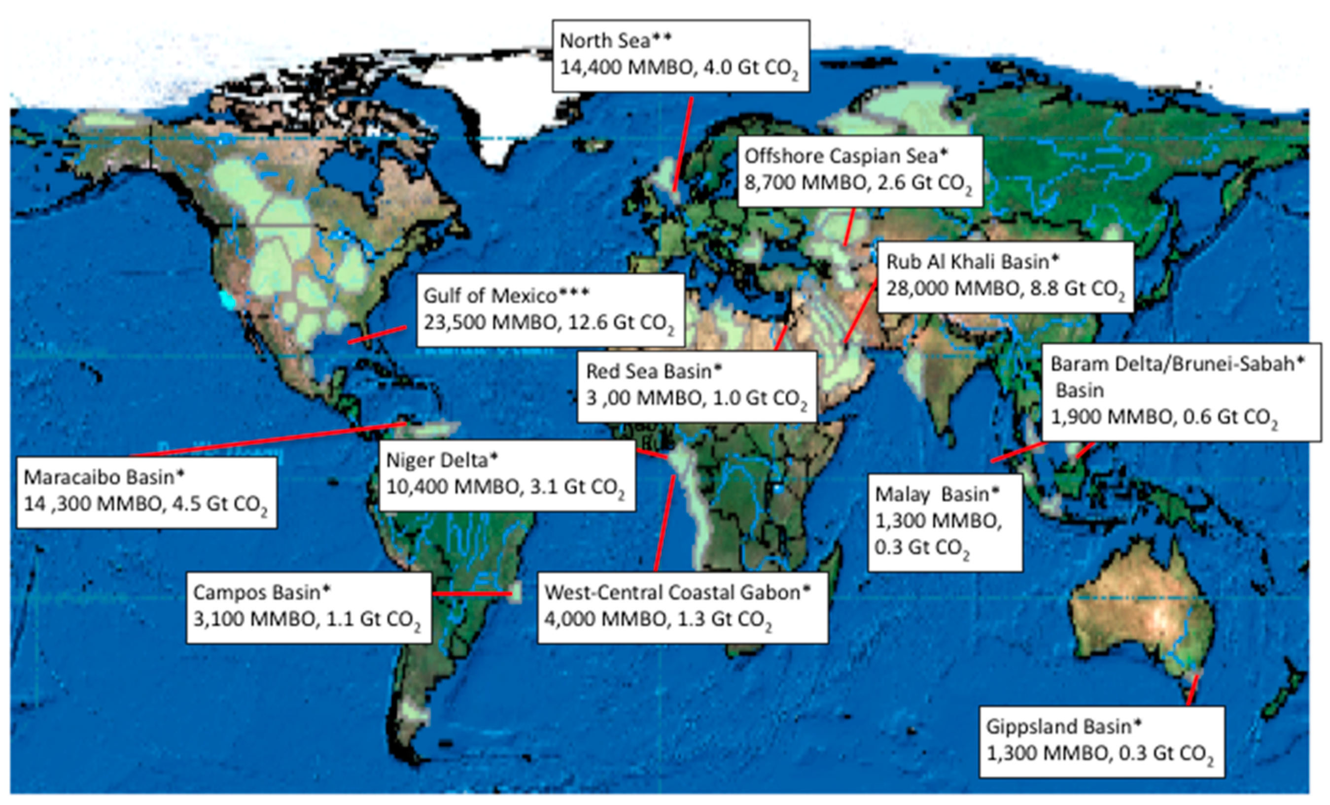
2.3. Global Tecchnical Potential for Incremental CO2-EOR Production and for CO2 Storage

Because a range of methods have been used to estimate the potential for EOR and CO2 storage, and because regional estimates seldom include the same oil fields, direct comparisons of various studies are therefore difficult. In particular, differences in methodologies cause challenges when trying to combine various estimates. The summary given here is based on a global overview in which the same approach was used for all assessed basins [16]. Therein, the technically recoverable oil from offshore CO2-EOR oil fields is 95.000 million barrels of oil (15.2 GSm3), with a potential for storage of 29.2 Gt CO2, giving a ratio of 0.307 tonnes CO2/barrel of oil. These estimates have been updated to include almost all fields in the Gulf of Mexico [2] and many, but not all, of the fields in the North Sea [5]. The results for incremental oil production and CO2 storage for the basins are shown in Figure 2. Table 1 gives the aggregated results.
Note that some important offshore basins are not included because of lack of information, e.g., the offshore parts of the North Slope in Alaska and the Timan-Pechora in Russia, as well as existing and future fields in the Barents Sea, on the Siberian Shelf, and in some minor offshore basins.

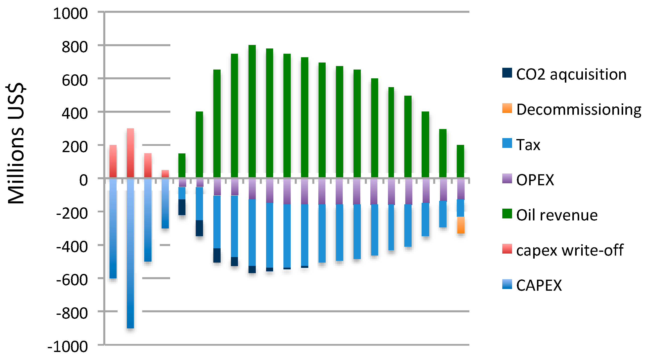
2.4. Economics of Offshore CO2-EOR

Several factors affect the profitability of offshore CO2-EOR projects. Some are global and/or regional in scale, but most are site specific. Table 2 lists some of these factors, which all will influence the cash flow of the project.
The different assumptions regarding key parameters, as listed in Table 2, make it difficult to systemise and/or compare results from the studies (e.g., References [2,4,5,10,11,13,17,18]). However, typical cash flow will show large expenses and no real income for the first few years, followed by many years with net oil revenues and expenses, mainly in terms of OPEX and tax. Figure 3 (based on examples in References [5,10]) illustrates this typical scenario. In reality, there will be more factors, such as deferred commissioning, to be included and the CO2 utilised may even become an income rather than an expense.

3. Case Studies

This section briefly describes the only operational offshore CO2-EOR project, which is located in Brazil, two European desk studies that evaluated the possibilities for large-scale offshore CO2-EOR by combining multiple CO2 sources with one or more potential oil fields, and a small pilot project in Vietnam.

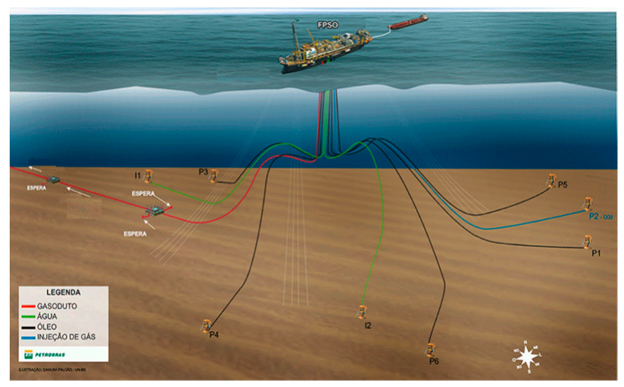
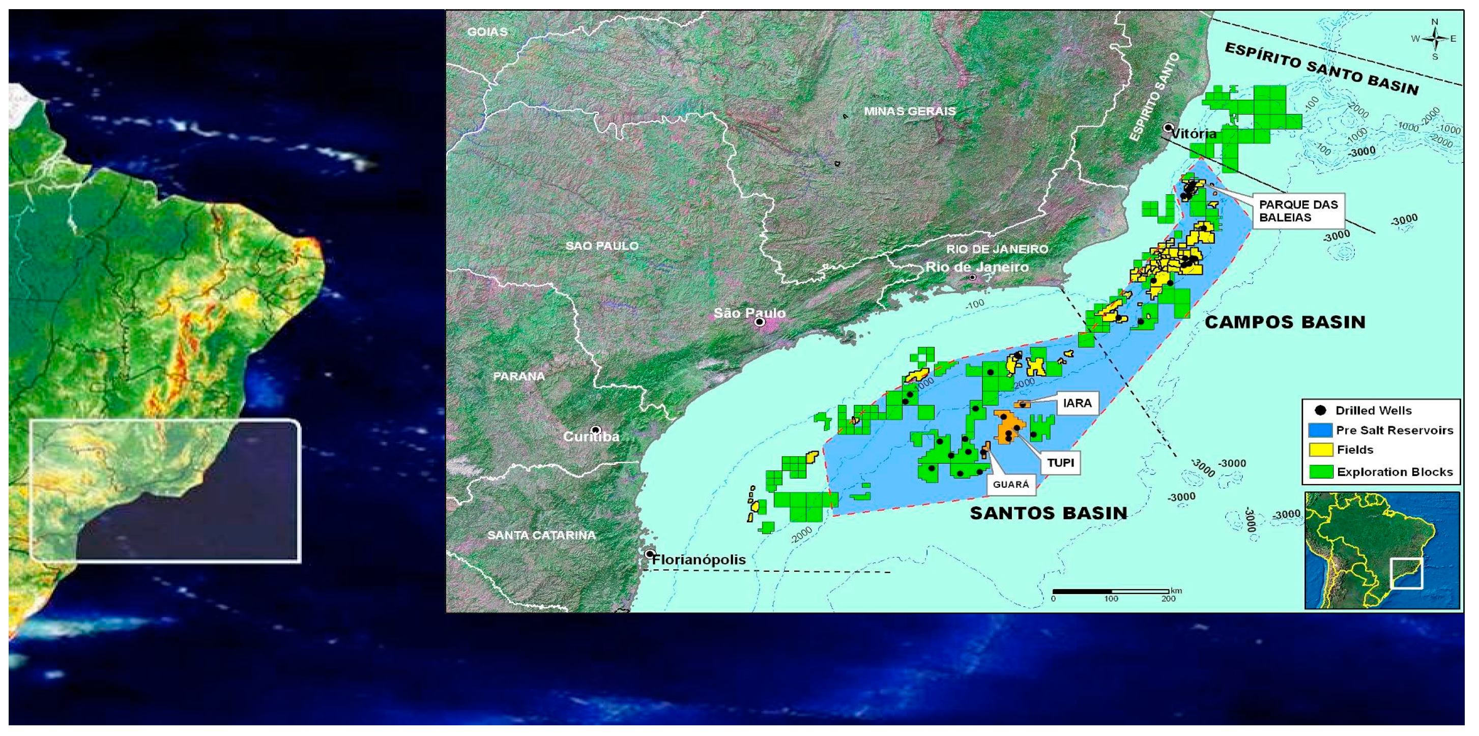
3.1. The Lula Project, Brazil

The Lula Field in southeast Brazil was discovered in 2006 in the area known as the Santos Basin Pre-Salt Cluster (SBPSC). It is located in deep waters (2,200 m) approximately 230 km from the coast (Figure 4). Reserves are estimated at 5–8 billion barrels. The field is developed by a joint venture composed of Petrobras (65%; Operator), BG E&P Brasil/Shell (25%), and Petrogal Brasil (10%).
The oil quality is 28–30 API and contains a significant amount of associated gas (gas/oil ratio [GOR] 200–300 m3/m3). The CO2 content in this associated gas is around 11%.
The main challenges identified in the early planning stages for the Lula Field development include the following:
  • Ultra-deep waters
  • Heterogeneous carbonate reservoirs
  • Presence of contaminants, mainly CO2, in the associated gas
  • Thick salt layer and very deep reservoirs that create seismic imaging complexities and drilling difficulties.
Since the early stages of Lula Field development, studies have been conducted to evaluate options for achieving a high ultimate economic recovery. EOR issues were addressed early in the planning stages, and because of the many limitations for offshore EOR (in terms of logistics, plants for fluid injections, and chemical processing) some options were considered unfeasible. To make up for these limitations, it was decided that offshore EOR for Lula would have to take advantage of the two abundant resources available: Seawater and the produced or imported gas.
Relatively low reservoir temperatures (60 to 70 °C) and the high original reservoir pressure made Lula well suited for miscible displacement processes of the oil by enriched CO2 streams or even by hydrocarbon gas. This suitability was confirmed by preliminary numerical simulation results, and, when combined with the strategic decision not to vent CO2 to the atmosphere, this made CO2-EOR an attractive solution for Lula. Because the available CO2 volume was not enough for a full-field application, a solution was adopted based on re-injection of the CO2-rich stream in either discharge wells or water-alternating-gas (WAG) injectors. In fact, the facilities were designed with the flexibility to inject an enriched CO2 stream or mixtures of CO2 and hydrocarbon gas.
Lula was developed with floating production storage and offloading (FPSO) units (Figure 5), mainly because of crude oil storage capability, avoidance of the need for construction of long-length oil pipelines, and other characteristics that allow a short-term completion with economic advantages in an ultra-deep offshore environment. The technology chosen for CO2 separation was via separation through membranes, as it was the only process identified that was able to handle a wide range of CO2 concentrations throughout the production life. Because membranes are sensitive to heavy hydrocarbon condensates and aromatics, the design included a dew-point control unit to remove heavy hydrocarbons upstream of the membranes.
So far, no major operational or reservoir problems have been detected. No gas or water injectivity losses upon cycling have been observed. No flow-assurance issues, such as hydrates, asphaltene or wax precipitation or severe inorganic scaling, were experienced. Injected perfluorocarbon gas tracers were easily injected and detected and are actively contributing to revisions of the geo-model.
The Lula project has shown that offshore CO2-EOR is possible once economic benefits and strategic incentives are in place. Offshore CO2-EOR requires good planning in advance, which should include reservoir characterisation, understanding of material challenges, robust and flexible development strategies, multi-well pilots, and modelling that includes comprehensive uncertainty analysis.

3.2. Examples of Desk Studies that Did Not Materialise
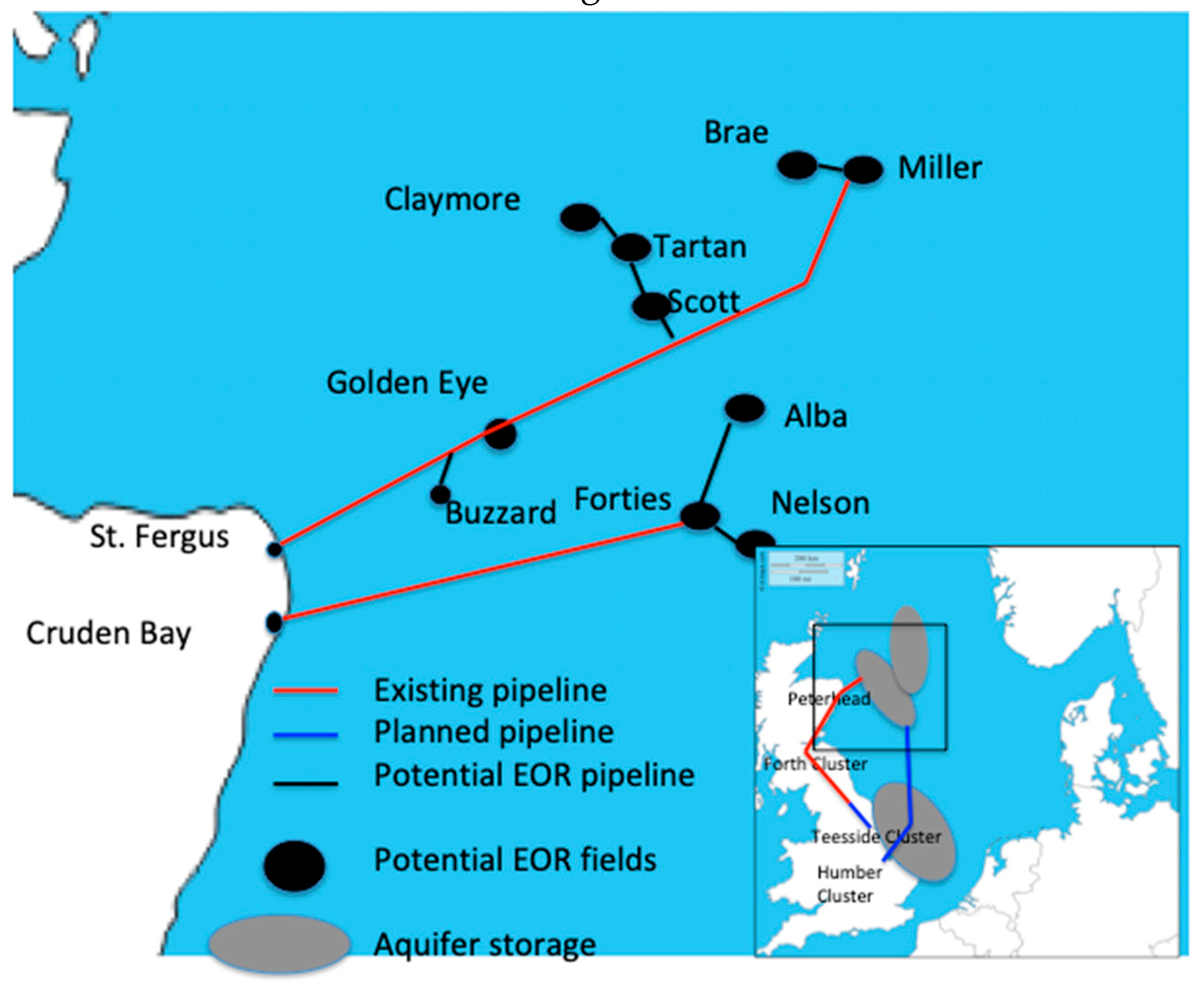
3.2.1. A UK Case

In the UK, several analyses have been conducted to investigate the potential for CO2-EOR in oil fields in the UK sector of the North Sea [9,20]. It is envisaged that CO2-EOR, if carefully navigated, can accelerate the emergence of a system for capturing and transporting CO2 for storage beneath the seabed (Figure 6). The potential for incremental oil production has been estimated at above 3000 million barrels, with associated storage of more than 1,430 million tonnes of CO2 for all fields on the UK continental shelf. The potential of fields in the Central North Sea (CNS) will be more than half of this amount. The fields in the CNS can possibly be served by some repurposing of existing offshore pipelines and the industrial infrastructure at St. Fergus.
The UK case study showed that CO2-EOR is a proven technology that can increase oil recovery and simultaneously store CO2 permanently in the subsurface. CO2-EOR can be economic if the CO2 is provided to EOR projects at a near-zero transfer price and if fiscal structures are introduced. However, so far the high cost and financial risk have hampered CO2-EOR deployment.

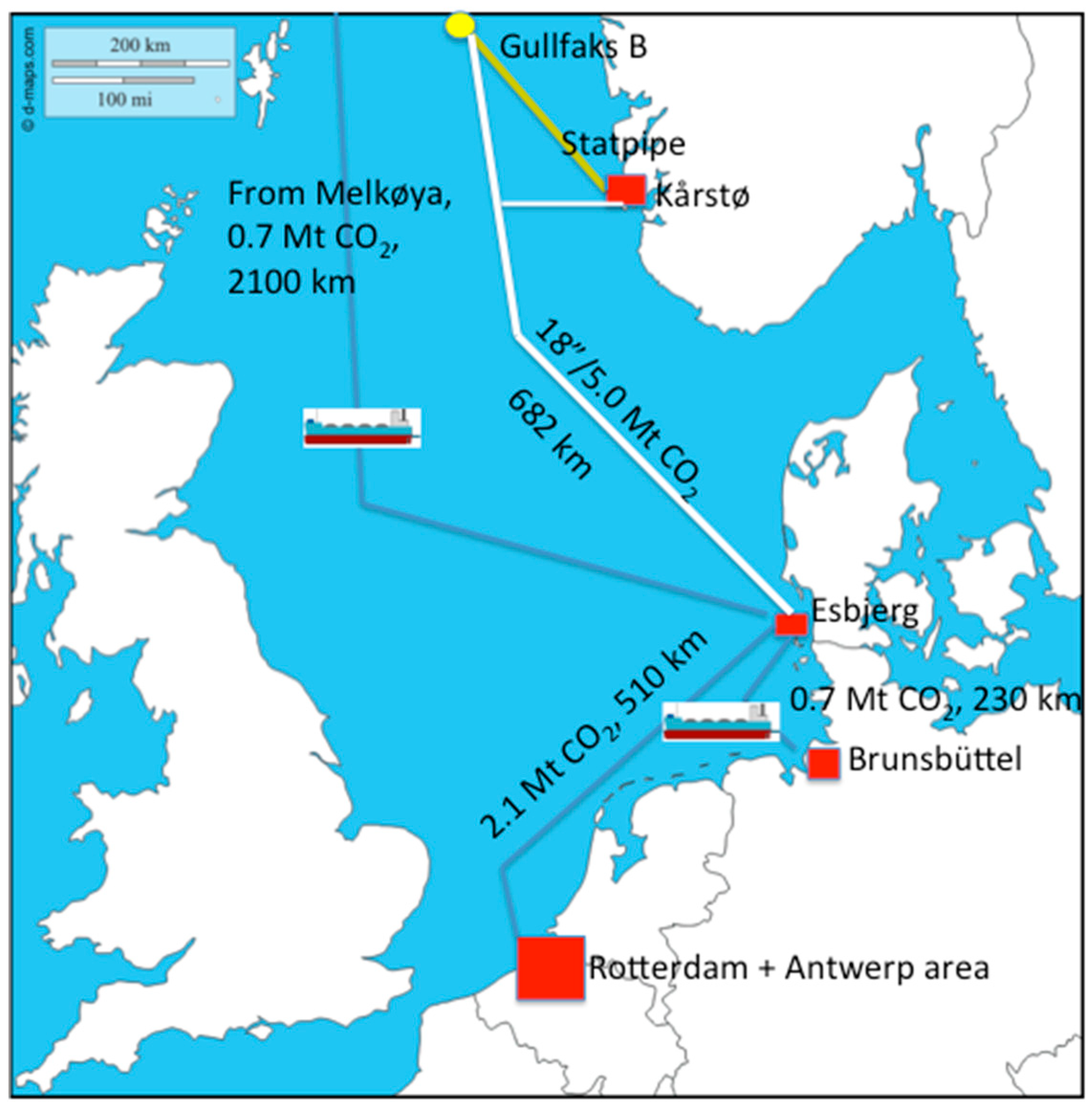
3.2.2. A Norwegian Case

In 2003–2004, Statoil (now Equinor) undertook studies of CO2-EOR for the Gullfaks Field [21,22,23]. It was assumed that 5 Mt CO2/year would be available for 10 years, which would give an increased oil production of 18.3 Sm3 relative to water injection, or 4.1% of oil in place. The concept was found to be technically feasible, but with the CO2 prices and credits, as well as oil price at that time, the economics were unfavourable for CO2-EOR.
Several options for CO2 supply were evaluated (Figure 7). In none of the options was a single geographical source sufficient for the needs of the Gullfaks project. Thus, scenarios with the delivery of CO2 from two or more sources were developed, including the following:
  • Five tonnes CO2/year transported CO2 by pipeline from two sources in Denmark to Gullfaks;
  • Ship transport of 5 Mt CO2/year from various distributed sources to the Kårstø terminal and a pipeline to Gullfaks;
  • Three and a half tonnes CO2/year from distributed sources by ship to Esbjerg, supplemented by 2 Mt CO2/year from a power station and transported by pipeline to Gullfaks.
In the end, the economic conditions for the Norwegian case were found to be unfavourable. Income from the additional oil that would have been produced would not make up for the cost of CO2 capture and transport.

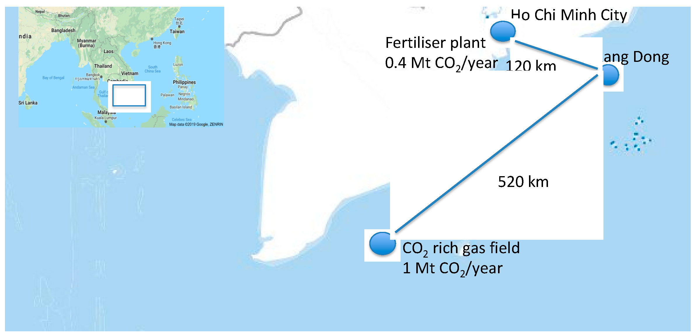
3.2.3. A Vietnamese Case

A joint Japanese-Vietnamese CO2-EOR pilot test was conducted on the Rang Dong Field offshore Vietnam in 2011 as a single-well Huff ‘n’ Puff following a preliminary study that indicated feasibility [24,25,26]. CO2 was injected into the well, which was flowed after soaking. The operation was successfully completed without any operational trouble or HSE issues. The CO2 Huff’n’Puff test provided the following results:
  • CO2 injectivity confirmation
  • Oil production increase
  • Water-cut reduction
  • Oil property changes by CO2 injection
  • Oil saturation changes before/after CO2 injection
However, the feasibility study involving two possible CO2 sources, a fertilizer plant and a CO2-rich gas field, with transportation by pipelines (Figure 8), showed that the cost was detrimental to the project, and it was terminated. The main cost drivers were the pipelines and modifications on the platform for separating and reinjecting recycled CO2. EOR using hydrocarbon gas has a significantly better economy (US $100 million vs. US $1000 million) despite lower EOR. The Japanese oil company JX concluded that CO2-EOR is technically feasible, but economically challenging for Rang Dong, due to the inconvenient location of the offshore project.

4. Approaches for Enabling Offshore CO2-EOR

4.1. Optimized and Smart Solutions

The case studies referenced above demonstrated that developing CO2-EOR on a large offshore oilfield in the late-life development stage has many significant hurdles, which can be summarized in terms of the following:
  • The large investment costs associated with the conversion and adaption of offshore platform facilities;
  • The lack of infrastructure to supply and handle sufficient volumes of CO2 to achieve a viable CO2-EOR project;
  • Competition with other more attractive oilfield development options, such as gas injection.
However, the growing need for large-scale carbon capture, utilisation, and storage (CCUS) implies that the barriers to deployment must be overcome. In order to stimulate incremental growth of new offshore CO2-EOR projects, the review identified and assessed some enabling options, including the following:
  • Using smart operational solutions for reducing project CAPEX and OPEX, e.g., by minimising the need for conversion of surface facilities and optimising the gas/CO2 recycling system [15].
  • Using late-life oilfield infrastructure. In certain cases, relatively minor modifications could be made to late-life, and generally smaller, offshore field developments where some CO2 handling capabilities are already in place, e.g., the K12-B gas field in the Dutch sector of the North Sea [27].
  • Using isolated oilfield satellite projects for dedicated CO2-EOR projects. There is considerable experience in the North Sea with subsea satellite field developments tied back to a main offshore oilfield project. There could be potential for using CO2-EOR on an isolated satellite field without incurring the larger conversion costs associated with a full field project.
  • Focusing on CO2-EOR for residual oil zone (ROZ) reservoirs. Residual oil zones located below oil/water contacts of many oil reservoirs have been identified as a significant new resource that could be realised using CO2-EOR [28,29].
  • CO2-EOR reservoir modelling, simulation, and optimisation issues. Reservoir mathematical modelling and simulation is a broadly used tool in the oil industry. CO2-EOR is more complex than conventional recovery techniques, such as phase behaviour, reaction with reservoir rock, and multiphase flow in porous media, and oil stability need to be characterised and included in mathematical models/simulators.

4.2. Emerging Technical Solutions for Offshore CO2-EOR and Storage

As argued earlier, offshore CO2-EOR can be expensive for the following reasons:
  • The need for treatment of well streams from an EOR flood. Existing offshore facilities generally have very limited space and weight reserves, and the materials utilised in existing processing systems are generally not suitable for streams with a high CO2 content.
  • Lack of sufficient and timely CO2 supply.
  • Insufficient additional oil recovery to cover the extra expenses.
The following options may enable projects to overcome these challenges are discussed below:
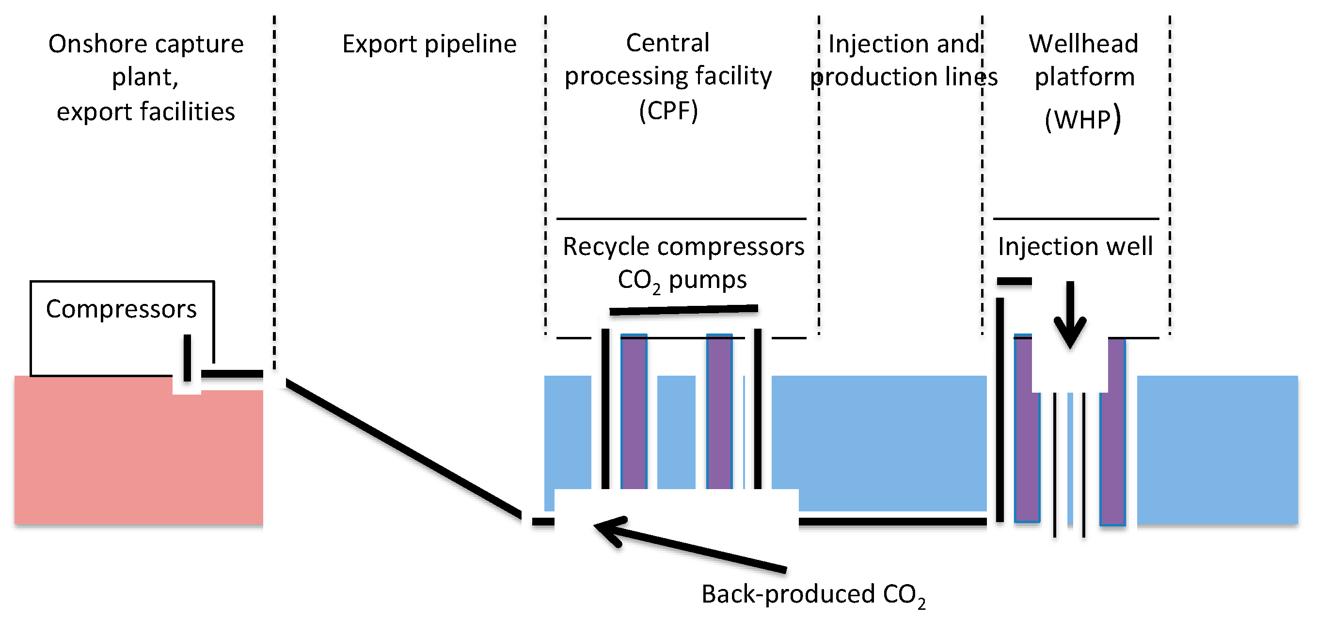
  • Subsea alternatives for topside CO2 processing modules used to separate CO2 for re-injection
  • Combined subsea production, power generation and CO2-EOR
  • Improved mobility control using CO2 foam
  • Solutions for enabling CO2 supply chains.

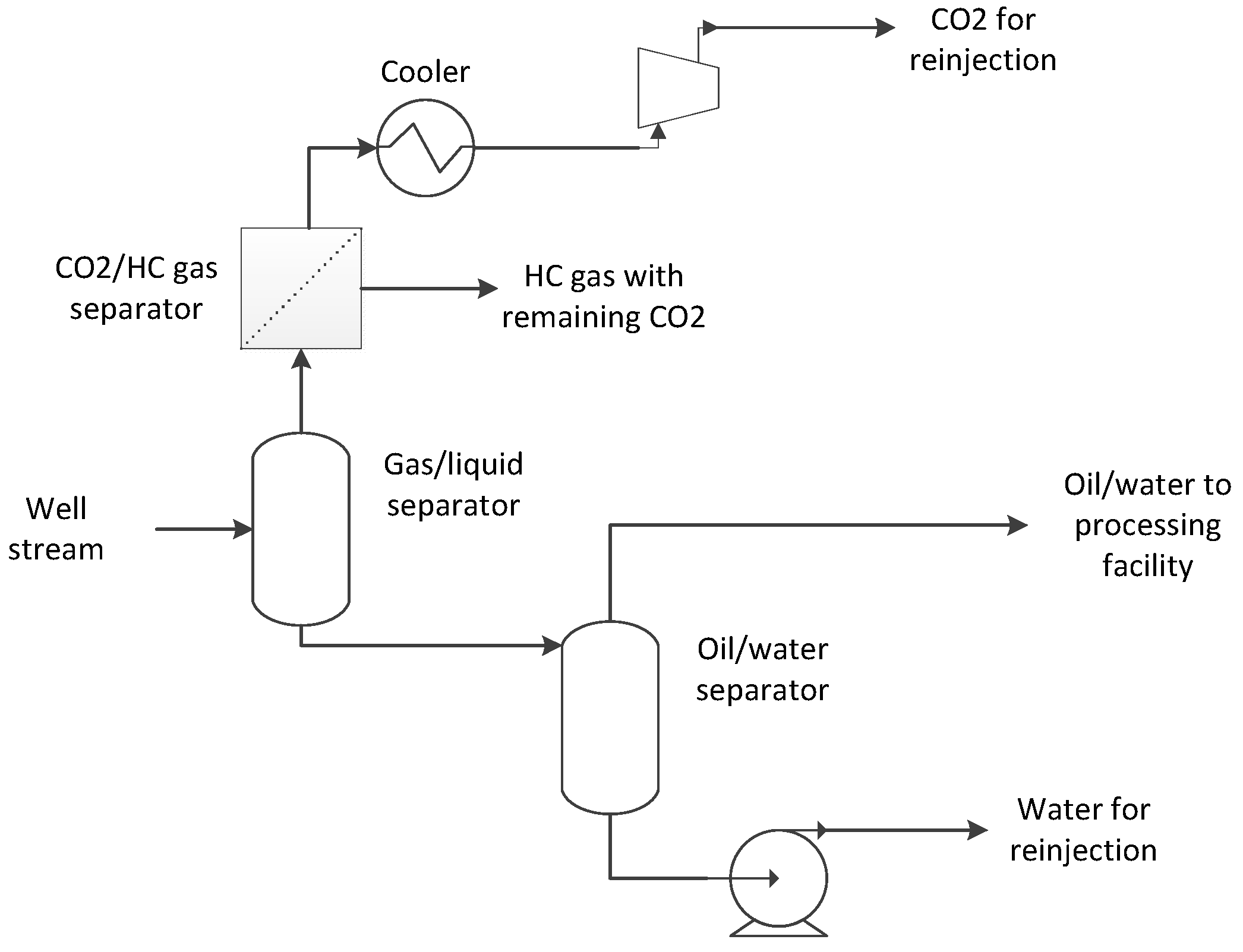
4.2.1. Subsea Solutions

A review of topside solutions for the separation of recycled CO2 can be found in Reference [14]. A subsea well treatment system could provide an attractive basis for an economically feasible offshore CO2-EOR gas-separation system.
A processing concept for CO2-EOR will depend on the specific requirements for each field and facility. The main functions of a proposed CO2-EOR processing concept are illustrated in Figure 9. After liquid and gas are separated, the liquid is taken into an oil/water separator and the water is re-injected into the reservoir. To achieve the required water quality for re-injection, the oil stream will still contain a considerable amount of water, but the removal of water significantly increases capacity in the produced water treatment system on the existing facility. Facilities operating in late life often have bottlenecks in the produced water treatment system. Additional steps can be introduced if needed, e.g., further degassing of the oil/water stream at lower pressure to remove more CO2.
The gas phase is directed to a separator (e.g., membranes) to separate the CO2 from hydrocarbon gas before the CO2 is compressed and re-injected. Depending on the gas compression requirements, more than one stage may be needed. In such cases, inter-stage cooling and demisting may be required. Cooling at the compressor discharge may be used to get the CO2 into a dense phase. Hydrocarbon gas with the remaining CO2 is sent to the processing facility.
Most of the building blocks for subsea processing exist, such as gas/liquid separators, liquid/liquid separators and de-oiling, coolers, compressors, pumps, subsea de-sanding equipment, control systems, and power systems.
One critical element in the subsea solution is the core technology for gas separation of CO2 and hydrocarbon gas, a process that must be qualified for subsea use. Known and emerging technologies for separating CO2 from other gases include the use of sorbents, solvents, membranes, and by supersonic separation. Descriptions of these methods are outside the scope of this review, but can be found in Reference [30].
For smaller reservoirs, an alternative is to have a simplified subsea processing system without bulk separation of CO2 (Figure 10). In this case, the entire gas phase (hydrocarbon gas and CO2) is compressed and re-injected. The liquid phase (oil and water) is produced to the existing topside facility.

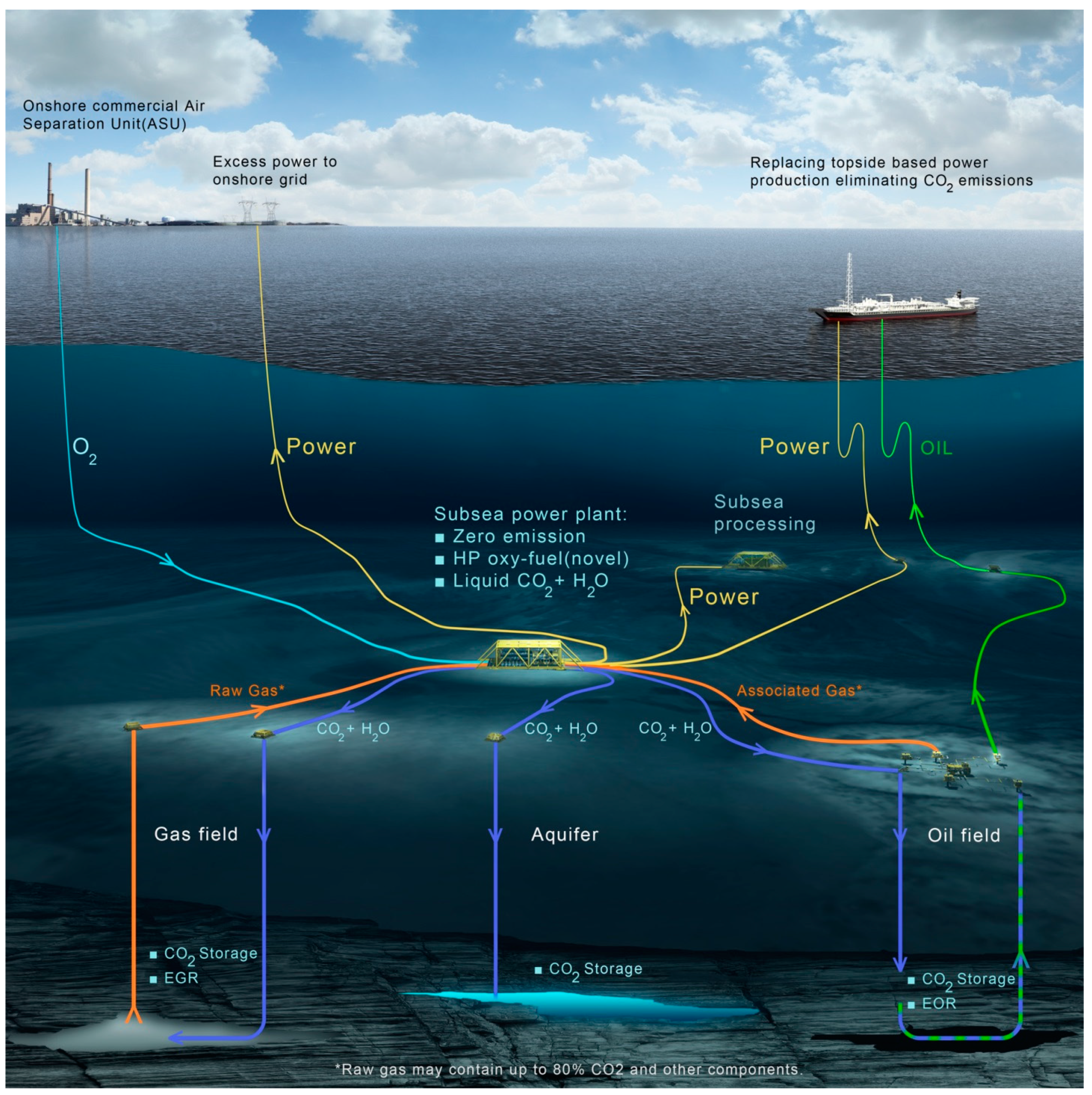
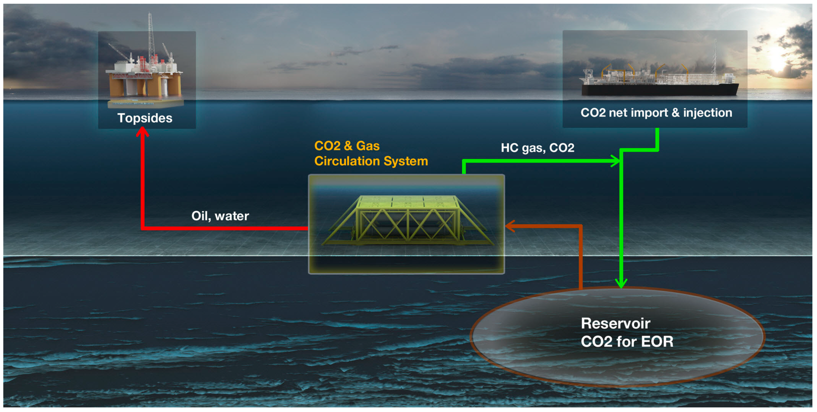
4.2.2. Combined Subsea Production, Power Generation and CO2-EOR

Aker Solution has suggested a zero-emission offshore power concept, called KRYPTON (Figure 11). Produced gas is burnt with oxygen from shore in a subsea power plant. The flue gas comprises CO2 and water, which are used in a simultaneous water-alternating-gas (SWAG) process in which CO2 is used as the less dense phase. Water is injected at the top of the reservoir formation and CO2 at the bottom of the formation. The power can be used to electrify offshore installations, thus reducing offshore emissions. Excess power could be sold to the grid. After its use, CO2 is permanently stored.
By locating the unit subsea, close to production and injection wells and with ample access to 4 °C seawater, the following benefits are achieved:
  • The robust oxy-fuel combustion process eliminates the need for pre-processing of the feed gas.
  • The high pressure, naturally provided at the wellhead, combined with the necessary cooling provided by the cold seawater, eliminates the need for costly postprocessing of the flue gas for reinjection.
  • The short distances to production and injection wells save much on costly piping infrastructure.

4.2.3. Mobility Control

Studies have been carried out to develop new generation injection techniques to increase oil production beyond the conventional CO2 injection and, at the same time, eliminate problems related to water injections, such as water shielding [31]. These techniques make use of increased miscibility of oil and injected CO2 at lower temperatures by conditioning the reservoir temperature around the injection well and in the path between injectors and producers. Modification of injection composition is another method suggested to achieve control over the CO2 front. Composition of the injected mixture is modified at cycles to create gas-like and liquid-like behaviour at the injection point, a process that resembles a WAG injection, but avoids unwanted effects, such as relative permeability hysteresis.
The CO2 storage capacity is strongly limited by the unstable displacement of water and oil because CO2 at reservoir conditions is very mobile and has very low viscosity, conditions that cause early CO2 breakthrough. Viscous fingering, gravity override, and flow in high-permeability pathways reduce the volumetric sweep and the effectiveness of CO2 injection processes. Foam is a potential remedy for this problem. Application of foam, by adding surfactants to the CO2, can give CO2 a more favourable mobility ratio relative to oil and water, which improves oil recovery and the net CO2 storage potential as also mobile water is also displaced, providing more storage volume for CO2. This process reduces the needs for handling and re-injection of produced CO2. Thus, CO2-foam EOR helps enable CCUS by reducing operational cost, increasing the commercial value of CO2, and providing improved oil-production revenue for the industry. Because of large well spacing in offshore situations, this technique should increase injection sweep efficiency considerably compared to that of onshore applications. These methods would be more affordable and effective than traditional methods, such as CO2 WAG or carbonated water injection in situations where pressure build-up can be an issue, water resources are scarce, or water shielding is the cause of concern during CO2-EOR floods in water-wet reservoirs.
Further development of offshore CO2-foam EOR will have to include knowledge transfer from onshore CO2-foam EOR pilots in Texas and from upscaling that may be incrementally moving from laboratory scale to onshore operations and to finally offshore pilots.
CO2-foam EOR mobility control may establish next generation CO2-EOR flooding. potentially providing less than 10% residual oil in swept zones. Foam and mobility control has significant potential for an enabling a “quantum leap” within EOR (Table 3) [2].

4.2.4. CO2 Transport as Part of the Supply Chain

Offshore CO2-EOR projects will be site and situation specific. The transportation mode of CO2 from the sources to the oil fields will depend, among many factors on the number of fields to be served, the supply of CO2, location of fields relative to sources (i.e., distances for transport), lifetime of the EOR project, and need for flexibility.
The technology for transportation is available and in use. The technology for CO2 pipelines is well established, and CO2 transportation infrastructure continues to be commissioned and built. However, there is only one offshore CO2 pipeline in operation (Snøhvit in Norway), and research, design, and development (RD&D) can still contribute to optimising the transport systems, thereby increasing operational reliability and reducing costs [32]. The need for RD&D applies, in particular, to understanding the impacts of impurities and validating predictive models for CO2 pipeline design. Compression will most likely be needed, in particular if pipelines are re-used to transport CO2. Subsea compression near the well (see Section 4.2.1) has the potential to become a cost-efficient alternative booster platform, offering extra compression power on an existing platform. If new, purpose-built CO2 pipelines are constructed, they may be able to operate at sufficient pressure so that re-compression at the field would not be required before injection into the reservoir.
Ship transport can be an alternative to pipelines where CO2 from several medium-sized (near) coastal emissions sources need to be transported to a common injection site or to a collection hub for further transport in a trunk pipeline to offshore storage. Transport of food-grade CO2 by ships and barges already takes place on a small scale (1000–2000 m3) in Europe. Several feasibility studies (see Reference [14]) have concluded that ship transport is not a technical barrier for the realization of full-scale offshore CO2-EOR projects. However, there are needs for technology optimisation and qualification of the first systems for large-scale projects. This applies in particular to offshore loading and offloading operations with options that include (1) offloading directly from the ship via buoy; and (2) offloading to offshore intermediate storage, either floating or fixed.

5. Monitoring, Verification, and Accounting (MVA)

The objective of this section is to review the available information on MVA applied to storage in offshore saline and depleted reservoirs and onshore CO2-EOR in order to consider the monitoring options that could be suitable for offshore EOR. No specific and detailed precedent tailored to this topic is currently available. References to the abundant publications on MVA activities for other subsets of geologic environments can be found in Reference [14].

5.1. Roles and Expectations of MVA for Offshore CO2-EOR

Motivational drivers for MVA programs will depend on the definition of the project and the nature of the regulatory structures in place. The drivers can be grouped into the following four categories, which can also overlap:
  • EOR operational needs: MVA tools for onshore CO2-EOR projects are often targeted at optimising CO2 utilisation, and it is currently unclear how the optimisation will be conducted offshore; however, various types of oilfield surveillance have been widely used, such as wellhead and bottom-hole pressure gauges, injection and production profile logs, saturation logging using tools, such as pulsed neutron devices, 3-D and 4D geophysical surveys, cross-wells surveys, and tracer test programs [33]
  • Drilling and operational regulatory requirements: Most hydrocarbon regulation focuses on the assurance of well integrity: These regulations are generally in place but may need modification for CO2-specific well integrity issues
  • Greenhouse gas accounting requirements: Monitoring to document storage efficiency and to provide assurance of CO2 containment during and after project operation is likely to become more important over the coming years. However, many components of monitoring programs for CO2-EOR are similar to those detailed for greenhouse gas (GHG) accounting [34], so only incremental changes are expected. For CO2-EOR projects, accounting is needed for CO2 that is produced with hydrocarbons, and some guidance on how this can be included can be found in Reference [35]
  • Risk and liability management: Risk management can be a major motivation for the implementation of monitoring and will be site specific in terms of site characteristics, operational condition, and local receptors. These parameters can be integrated into a risk assessment. for which. a framework is provided in Reference [33]

5.2. Differences between MVA for CO2-EOR and Storage of CO2

A number of key differences in the risk profile are noted between CO2-EOR and CO2 storage (Table 4 [36]). These differences should trigger differences in the monitoring approach. Parameters that lower risk include (1) active management of the lateral extent of the CO2 plume and of pressure-elevation area and magnitude of pressure elevation because of production; (2) better characterization of the injection zone because of operational data gained during production, such as porosity, permeability, connectivity, and boundary conditions in the reservoir; (3) previously demonstrated effectiveness of traps and seals because of hydrocarbon trapping over geologic time; and (4) the added benefit of CO2 trapping in the oil phase because of the CO2-oil miscibility effect (in addition to the CO2 that is trapped by dissolution in water).

5.3. Differences between MVA for Onshore CO2-EOR and Offshore CO2-EOR

The following differences between onshore and offshore CO2-EOR that need to be considered when designing MVA programs include:
  • Offshore, wells tend to have deviated, multilateral, and of newer construction than onshore wells. These factors might impact risk profiles and optimisation of MVA tools deployed. The wider well spacing might create larger areas of elevated pressure than is typical onshore.
  • Onshore the traditional highest concern has been contamination of groundwater or surface water resources. Offshore, hydrocarbons may leak into marine environments, where concerns may be even higher than in onshore settings.
  • It is not yet clear how the brine-handling options in an offshore setting will affect the operations for offshore CO2-EOR projects.
  • On the more on the speculative side, offshore CO2-EOR may be deployed with a stronger initial emphasis on greenhouse-gas accounting, leading to high and constant rates of CO2 injection. High rates of CO2 injection might elevate offshore risk as compared to traditional onshore EOR by allowing CO2 and elevated pressure to migrate outside of the area of the field under control by production.

5.4. Transition CO2-EOR to Storage—Impact on Monitoring

Monitoring issues for offshore CO2-EOR projects that transition from EOR to storage offshore will be the same as for onshore projects and include assurance monitoring; a requirement for more environmental monitoring over a larger area of review or influence; baseline monitoring prior to start of CO2 injection; and monitoring after cessation of CO2 injection for various periods of time, depending on regulations in the respective jurisdiction [37,38]. These activities are feasible with known technology and can be met by operators, but they will have cost impacts.

6. Regulatory Issues

6.1. General

Because offshore CO2-EOR offshore has yet to commence, with the exception of one project in Brazil, regulatory regimes for the processes have not yet been developed or tested. Regulatory regimes do exist for CO2 storage offshore and CO2-EOR onshore. Initial international policy on offshore CO2 storage took the legal view that storage of CO2 in the water column or sub-seabed may be viewed as dumping of waste into the marine environment, and changes were made to permit subsea storage in deep geological Formations. A full description of the international regulations for CO2 storage offshore is provided in Reference [34].
However, because any use of CO2 in sub-seabed injection projects is neither prohibited nor covered by any specific regulations, CO2 for EOR is not covered by the CO2-storage specific regulations that have been developed. Any offshore CO2-EOR activity is likely to be regulated by oil and gas or petroleum legislation, whereas CO2 storage is more likely to be governed by specific regulations. Both will be jurisdiction specific. Some aspects of the different types of legislation are as follows:
  • Presently, CO2-EOR projects are not required to undertake the same extent of site analysis and evaluation —with respect to capacity, integrity and monitoring—as CO2 storage projects. CO2-EOR projects that are considered for transition to carbon capture storage (CCS) projects after cessation of oil production must bear this in mind.
  • According to oil-field regulations, a CO2-EOR project ends when the oil production ceases and the field is abandoned. If seeking to transition to a CO2 storage project, issues around liability and CO2 ownership may arise.
  • GHG emissions accounting requirements, including emissions connected to recycling and injection processes and the potential for CO2 losses during recycling may also be an issue.
Regulations on the transition from a CO2-EOR project to a CCS project are discussed in Reference [37] (a shorter version is found in Reference [38]). Although mainly concerned with onshore CO2-EOR, the report [37] concludes that “There are no specific technological barriers or challenges per se in transitioning and converting a pure CO2-EOR operation into CO2 storage operation. The main differences between the two types of operations stem from legal, regulatory and economic differences between the two.”
Regulations for CO2 storage, CO2-EOR and the transition between the two were examined in Reference [39] for the following jurisdictions: United States of America (USA); the Canadian provinces of Alberta, Saskatchewan and British Columbia; the European Union (EU); Australia; and Brazil. It was found that the EU is the only jurisdiction that has regulations for all three in place (Table 5). Table 5 shows that regulations for the transition from CO2-EOR to CO2 storage are the least developed.
In conclusion, there is a need for a clarification of the legislation covering the transition from CO2-EOR to CO2 storage.

6.2. Some Country and Region Specific Examples

In Brazil, the state-owned oil company Petrobras operates the Lula oilfield offshore in the Santos Basin and injects CO2 into producing oil reservoirs. This enterprise is undertaken within the framework of existing petroleum legislation; there is no CCS regulation in place in Brazil. No carbon credits are sought for this activity.
In the Gulf Cooperation Council (GCC) countries, it seems that CO2-EOR activities can generally be regulated under legislation for oil and gas exploration and production. In all GCC countries, state-owned enterprises dominate and have full concessions of all oil and gas production, and to a large extent, of downstream refining and petrochemical sectors. State-owned operators are generally self-regulating [12].
In the United Kingdom, a study by the Scottish Carbon Capture and Storage Centre (SCCS) concluded that “it would seem possible that CO2-EOR activities would be regulated under existing laws and voluntary practices, with little or no amendments” [9]. A more recent and somewhat broader study identified areas in the current UK and EU legislation that need to be addressed, although these were focussed on the more generic issues of property rights and trans-boundary movement of CO2, more generic issues [40].
In the United States, the offshore area consists of submerged lands under the jurisdiction of the coastal states, as well as submerged lands under Federal jurisdiction, referred to as the Outer Continental Shelf (OCS). The United States (US) Department of the Interior (DOI) authorizes and regulates the development of mineral resources (including oil and gas) and certain other energy and marine related uses on the OCS. The US Environmental Protection Agency (EPA) Underground Injection Control (UIC) program regulates injection wells onshore and in the submerged lands of the coastal States. CO2-EOR wells are regulated as Class II wells, i.e., wells used exclusively to inject fluids associated with oil and natural gas production. Wells for CO2 storage are regulated as Class VI injection wells. The EPA has promulgated regulations for Class VI wells, which include specific requirements for site selection, well design and construction, and MVA of injectate-CO2, and long-term monitoring even after CO2 injection has ceased. The EPA has also developed guidance to support the Class VI regulatory requirements. It has been recommended to develop a comprehensive US framework for leasing and regulating sub-seabed CO2 storage operations on the OCS; because these guidelines are not yet established, the existing regulatory framework is shared across multiple Federal agencies, including the DOI and EPA, and may have jurisdictional overlaps and gaps, including for the transition from CO2-EOR to sub-seabed geologic storage of CO2.
It appears that offshore CO2-EOR activities can fall under existing oil and gas regulation, and regulatory uncertainty is not assumed to constitute a barrier to the broader deployment of the technique. However, if the intention is for the CO2-EOR to demonstrate long-term storage or to seek an incentive such as carbon credits, additional CCS regulatory requirements will need to be met. The flexibility in the current international requirements (e.g., London Convention, OSPAR, EU) may have to be investigated and modified, e.g., for the CO2 stream to be considered “overwhelmingly CO2.”

7. Conclusions

CO2-EOR has been used onshore for many decades, particularly in North America, but also to some extent in Europe (e.g., Hungary and Croatia). In the US, the technique currently contributes 280,000 barrels of oil per day, just over 5% of the total U.S. oil production. Offshore, there is only one active project, at the Petrobras-operated Lula Field offshore Brazil.
This review has revealed few, if any, technical barriers to offshore CO2-EOR. The lack of offshore CO2-EOR projects appears to be caused primarily by several non-technical barriers, some of which are shared by offshore CO2 storage. The barriers fall in several categories:
  • Related to the implementation of CCS in general (where politicians and other decision makers can contribute):
    Lack of access to sufficient and timely supply of CO2
    Lack of business models, especially for offshore CO2-EOR,
  • Related to technology:
    High investment costs, CAPEX and additional operational costs, OPEX
    Loss of production while modifying facilities represents an additional up-front cost. Technology development can contribute to cost reduction, although the value is also dependent on the required rate of return.
  • Related to revenue: Reservoir characteristics are usually well known for mature oil fields, but uncertainties still surround reservoir performance and the yield of addition oil. Uncertainties around the revenues, namely the oil price and the cost of CO2, include the following:
    Volatile oil prices that may prevent operators from implementing offshore CO2-EOR unless new business models and/or changed tax regimes are implemented to de-risk investments.
    Uncertainties around the price of CO2 that the oil-field operator must pay to the CO2 supplier, including the price of the CO2 itself and the transportation costs. The former will often be subject to negotiations between seller and buyer and could be influenced by CO2 prices in a trading scheme.
  • Regulatory issues:
    Global development of consistent regulatory regimes for CO2-EOR and the transition from CO2-EOR to CO2 storage in the offshore environment need to be developed globally.
    Deciphering requirements that different jurisdictions will place on monitoring underground CO2. Although not being a barrier in itself, monitoring will require different considerations than those for offshore CO2 storage and to onshore CO2-EOR.
    Clarity around long-term liability

8. Recommendations

The findings described in the Conclusions need to be followed up to secure application of emerging technologies and improvements in political and financial incentives. The key recommendations from this work are that governments and industry should work together to do the following:
Start planning regional hubs and transportation infrastructures for CO2. This will give access to sufficient supplies of CO2 for EOR, reducing the CAPEX for individual one-on-one source linkages for CO2-EOR projects, and allowing flexibility with respect to the reduced need for fresh CO2 and temporary stops in the CO2 production. Such planning will also contribute to an increase in the pace in deployment of CCS.
Support RD&D to develop new technologies. Development of new technologies can reduce the need for modifications and new equipment (such as better mobility control or subsurface separation systems), thus reducing CAPEX and OPEX for offshore CO2-EOR. Use of existing pipelines may also be a way to keep investment costs down.
Develop business models for offshore CO2-EOR. Such business models must include fiscal incentives (e.g., in term of taxes or tax rebates), and must be able to hold up robustly against volatile oil prices and uncertain CO2 prices.
Continue to develop regulations specific to offshore CO2-EOR. Regulations should include monitoring CO2 in the underground, both during and particularly after closure, as well as guidelines for when the field transfers into a CO2 storage site.

Author Contributions

Introduction: L.I.E.; Review of Offshore CO2-EOR Storage: L.I.E.; Case studies: R.A.M.V. and L.I.E.; Approaches for Enabling Offshore CO2-EOR: P.H.N., P.R., A.G., Z.E., S.H., B.N., G.I.O.; Monitoring, Verification, and Accounting (MVA): S.H.; Regulatory issies: M.B. and T.D.

Funding

This research received no external funding.

Conflicts of Interest

The authors declare no conflict of interest.

References

  1. Ueda, Y.; Uchiyama, T.; Kawahara, Y.; Hatakeyama, A. CO2-EOR Huff ‘n’ Puff Pilot Test in Rang Dong Oilfield, offshore Vietnam. J. Jpn. Assoc. Pet. Technol. 2013, 78, 188–196. [Google Scholar] [CrossRef]
  2. Malone, T.; Kuuskraa, V.; DiPietro, P. CO2-EOR Offshore Resource Assessment, Report DOE/NETL-2014/1631. 2014; 90p. Available online: http://www.netl.doe.gov/energy-analyses/temp/FY14_CO2-EOROffshoreResourceAssessment_060114.pdf (accessed on 17 May 2019).
  3. Hustad, C.W.; Austell, J.M. Mechanisms and Incentives to Promote the Use and Storage of CO2 in the North Sea; European Energy Law Report: Cambridge, UK, 2004; pp. 355–380. [Google Scholar]
  4. Holt, T.; Lindberg, E.; Wessel-Berg, D. EOR and CO2 disposal—Economic and capacity potential in the North Sea. Energy Procedia 2009, 1, 4159–4166. [Google Scholar] [CrossRef]
  5. Pershad, H.; Durusut, E.; Crerar, A.; Black, D.; Mackay, E.; Olden, P. Economic Impacts of CO2-Enhanced oil Recovery for Scotland. Element Energy Report to Scottish Enterprise. 2013. Available online: https://www.scottish-enterprise.com/knowledge-hub/articles/publication/co2-enhanced-oil-recovery (accessed on 2 February 2017).
  6. Durust, E.; Pershad, H. CO2-EOR in the UK: Analysis of Fiscal Initiatives. Final Non-Technical Report, Element Energy 2014. Available online: http://www.element-energy.co.uk/wordpress/wp-content/uploads/2014/06/SCCS_CO2-EOR_JIP-TaxStudyNon-technicalReport.pdf (accessed on 17 May 2019).
  7. Norwegian Petroleum Directorate (NPD), 2014 CO2 Storage Atlas. Available online: https://www.regjeringen.no/en/aktuelt/CO2-storage-atlas-for-the-Norwegian-continental-shelf/id760077/ / (accessed on 17 May 2019).
  8. Energy Research Partnership. Prospects for CO2-EOR in the UKCS 2015. Available online: http://erpuk.org/wp-content/uploads/2015/10/ERP_CO2-EOR-Report-Oct-2015.pdf (accessed on 17 May 2019).
  9. Scottish Carbon Capture and Storage (SCCS). CO2 Storage and Enhanced Oil Recovery in the North Sea. Securing a Low-Carbon Future for the UK. CO2-EOR Joint Industry Project 2015. Available online: http://www.sccs.org.uk/expertise/reports/co2eor-joint-industry-project (accessed on 30 January 2017).
  10. Welkenhuysen, K.; Meyvis, B.; Piessens, K. Techno-Economic Evaluation of CO2-EOR in the North Sea. Scottish Carbon Capture and Storage (SCCS) CO2-EOR Joint Industry Project. 2015. Available online: https://pdfs.semanticscholar.org/f54c/49577acbb72d52ca06be06a499591afae5e5.pdf (accessed on 20 May 2019).
  11. Welkenhuysen, K.; Meyvis, B.; Piessens, K. A profitability study of CO2-EOR and subsequent CO2 storage in the North Sea under low oil market prices. Energy Procedia 2017, 114, 7060–7069. [Google Scholar] [CrossRef]
  12. IEAGHG. Regional Assessment of Barriers to CO2 Enhanced Oil Recovery in the North Sea, Russia and the GCC States. IEAGHG Report 2016/11. 2016. Available online: http://www.ieaghg.org/publications/technical-reports/129-publications/new-reports-list/718-2016-11 (accessed on 17 May 2019).
  13. Lindeberg, E.; Grimstad, A.-A.; Bergmo, P.; Wessel-Berg, D.; Torsæter, M.; Holt, T. Large-scale tertiary CO2 EOR in mature water flooded Norwegian oil fields. Energy Procedia 2017, 114, 7096–7106. [Google Scholar] [CrossRef]
  14. Carbon Sequestration Leadership Forum (CSLF) Technical Group. Task Force on Offshore CO2-EOR: Enabling Large-Scale CCS Using Offshore CO2 Utilization and Storage Infrastructure Developments. 2017. Available online: https://www.cslforum.org/cslf/sites/default/files/documents/OffshoreEORTaskForce-FinalReport.pdf (accessed on 17 May 2019).
  15. Goodyear, S.G.; Koster, M.P.; Marriott, K.A.; Paterson, A.; Sipkema, A.W.; Young, I.M. Moving CO2 EOR Offshore. SPE 144939. 2011. Available online: https://www.onepetro.org/conference-paper/SPE-144939-MS (accessed on 17 May 2019).
  16. IEAGHG. CO2 Storage in Depleted Oilfields: Global Application Criteria for Carbon Dioxide Enhanced Oil Recovery, Report 2009/12. 2009. Available online: http://www.ieaghg.org/docs/General_Docs/Reports/2009-12.pdf (accessed on 17 May 2019).
  17. Kemp, A.G.; Kasim, S. The economics of CO2-EOR cluster developments in the UK Central North Sea. Energy Policy 2013, 62, 1344–1355. [Google Scholar] [CrossRef]
  18. Vidas, H.; Hugman, B.; Chikkatur, A.; Venkatesh, B. Analysis of the Costs and Benefits of CO2 Sequestration on the U.S. Outer Continental Shelf; OCS Study BOEM 2012-100; U.S. Department of the Interior, Bureau of Ocean Energy Management: Herndon, VA, USA, 2012.
  19. Seabra, P.N.; Grava, W.M. Petrobras’ Offshore CO2 Management—Pre-Salt Development Management. Presented at the 2014 COP 20 Side Event, Lima, Peru, 6 December 2014; Available online: http://www.ieaghg.org/docs/presentations/COP_20_-_Side_Event_Petrobras_Public.pdf (accessed on 17 May 2019).
  20. Reid, W. A Selective Literature Review of CO2 EOR in the UK North Sea Continental Shelf; Aiken Reid Ltd: Aberdeen, UK, 2015. [Google Scholar]
  21. Ministry of Petroleum and Energy, Norway. Enhanced Recovery on the Norwegian Continental Shelf (in Norwegian). 2010. Available online: https://www.regjeringen.no/globalassets/upload/oed/pdf_filer/oktutvinning.pdf (accessed on 7 May 2019).
  22. Berger, B.; Kaarstad, O.; Haugen, H.A. Creating a Large-Scale CO2 Infrastructure for Enhanced Oil Recovery. Presented at the Seventh International Conference on Greenhouse Gas Control Technologies (GHGT-7), Vancouver, BC, Canada, 5–9 September 2004. [Google Scholar]
  23. Augustsson, H.; Grinestaf, G.H. A Study of IOR by CO2 Injection in the Gullfaks Field, Offshore Norway. Presented at the 13th European Symposium on Improved Oil Recovery, Budapest, Hungary, 25–27 April 2005. [Google Scholar]
  24. Uchiyama, T.; Mitsuishi, H.; Ueda, Y.; Nishizaki, A.; Okabe, H.; Takagi, S.; Mitsuishi, H.; Kawahara, Y.; Huy, L.; Trung, P.N.; et al. Evaluation of a Vietnam Offshore CO2 Huff-n-Puff Test. Presented at the SPE Symposium on Improved Oil Recovery, Tulsa, OK, USA, 14–18 April 2012. [Google Scholar]
  25. Ha, G.T.; Tran, N.D.; Vu, H.H.; Takagi, S.; Mitsuishi, H.; Hatakeyama, A.; Uchiyama, T.; Ueda, Y.; Nguyen, T.V.; Phan, T.N.; et al. Design & Implementation of CO2 Huff-n-Puff Operation in a Vietnam Offshore Field. In Proceedings of the Abu Dhabi International Petroleum Exhibition & Conference, Abu Dhabi, UAE, 11–14 November 2012. [Google Scholar]
  26. Kawahari, Y.; Hatakeyama, A. Offshore CO2-EOR Pilot Project in Vietnam. Presented at the Carbon Sequestration Leadership Forum (CSLF), Tokyo, Japan, 5 October 2016; Available online: https://www.cslforum.org/cslf/sites/default/files/documents/tokyo2016/Kawahara-VietnamEORProject-Workshop-Session1-Tokyo1016.pdf (accessed on 17 May 2019).
  27. Kreft, E.; Brouwer, G.K.; Hofstee, C.; Wildenborg, A.F.B.; Audigane, P.; Gozalpour, F.; Geel, C.R. Results of the Second Test Program in K12-B, a Site for CO2 Storage and Enhanced Gas Recovery. Presented at the 68th EAGE Conference and Exhibition, Incorporating SPE EUROPEC, Vienna, Austria, 12–15 June 2006. [Google Scholar]
  28. Melzer, L.S.; Kuuskraa, V.A.; Koperna, G.J. The Origin and Resource Potential of Residual Oil Zones. Presented at the SPE Annual Technical Conference and Exhibition 2006, San Antonio, TX, USA, 24–27 September 2006. [Google Scholar]
  29. Harouaka, A.; Trentham, B.; Melzer, S. Long Overlooked Residual Oil Zones (ROZ’s) Are Brought to the Limelight. In Proceedings of the SPE Unconventional Resources Conference, Calgary, AB, Canada, 5–7 November 2013. [Google Scholar]
  30. IEAGHG. Assessment of Emerging CO2 Capture Technologies and Their Potential to Reduce Costs. 2014/TR4. 2014. Available online: http://www.ieaghg.org/docs/General_Docs/Reports/2014-TR4.pdf (accessed on 17 May 2019).
  31. Nazarian, B.; Cavanagh, A.; Ringrose, P.; Paasch, B. Composition Swing Injection for CO2 Storage and EOR. Presented at the Abu Dhabi International Petroleum Exhibition and Conference, Abu Dhabi, UAE, 10–13 November 2014. [Google Scholar]
  32. GCCSI. The Global Status of CCS; CCS Technologies: Melbourne, Australia, 2015. [Google Scholar]
  33. Cooper, C. (Ed.) A Technical Basis for CO2 Storage. CO2 Capture Project; CPL Press: Newbury, UK, 2009; Available online: www.co2captureproject.org (accessed on 17 May 2019).
  34. CSLF. Technical Barriers and R&D Opportunities for Offshore, Sub-Seabed Storage of CO2. 2015. Available online: https://www.cslforum.org/cslf/sites/default/files/documents/OffshoreStorageTaskForce_FinalCombinedReport.pdf (accessed on 17 May 2019).
  35. ISO. ISO 27916—Carbon Dioxide Capture, Transportation and Geological Storage—Carbon Dioxide Storage Using Enhanced Oil Recovery (CO2-EOR); International Organization for Standardization: Geneva, Switzerland, 2017. [Google Scholar]
  36. Hill, B.; Hovorka, S.; Melzer, S. Geologic carbon storage through enhanced oil recovery. Energy Procedia 2013, 37, 6808–6830. [Google Scholar] [CrossRef]
  37. CSLF. Technical Challenges in the Cnversions of CO2-EOR Projects to CO2 Storage Projects. 2013. Available online: https://www.cslforum.org/cslf/sites/default/files/documents/CO2-EORtoCCS_FinalReport.pdf (accessed on 17 May 2019).
  38. Eidan, A.A.; Bachu, S.; Melzer, L.S.; Eide, L.I.; Ackiewicz, M. Technical Challenges in the Conversion of CO2 EOR Projects to Storage Projects. In Proceedings of the SPE Enhanced Oil Recovery Conference, Kuala Lumpur, Malaysia, 11–13 August 2015. [Google Scholar]
  39. CCP. Best Practice in Transitioning from CO2 EOR to CO2 Storage: Report for CCPS Policies and Incentives Group. 2016. Available online: http://www.co2captureproject.org/viewresult.php?downid=228 (accessed on 17 May 2019).
  40. Carruthers, K. Metal Mobility in Sandstones and the Potential Environmental Impacts of Offshore Geologic Storage. Ph.D. Dissertation, University of Edinburgh, Edinburgh, UK, 2016; 266p. [Google Scholar]
Figure 1. Schematic diagram of offshore CO2-EOR project facilities. Based on an illustration in Reference [15].
Energies 12 01945 g001
Figure 2. Basins for which the potential for incremental oil production and CO2 storage have been assessed. Sources: * IEAGHG (2009) [16]; ** Pershad et al. (2013) [5]; and *** IEAGHG (2016) [12].
Energies 12 01945 g002
Figure 3. Example of possible cash flow in an offshore CO2-EOR project. All numbers are fictitious, but the presentation form is based on examples in References [5,10]. In reality, more factors, such as deferred commissioning, will be included.
Energies 12 01945 g003
Figure 4. The Santos and Campos Basins with the location of the Lula Field. From Reference [19].
Energies 12 01945 g004
Figure 5. Typical constellation for water-alternating-gas (WAG) and CO2-EOR using an floating production storage and offloading (FPSO) unit. From Reference [19].
Energies 12 01945 g005
Figure 6. The conceptual vision of CO2 storage beneath the North Sea, linked to emission sources with capture. The main map, simplified from Reference [17], shows fields in the UK Central North Sea that have been found particularly suitable technically and economically for CO2-EOR. Insert: Simplified from Scottish carbon capture and storage (SCCS) [9].
Energies 12 01945 g006
Figure 7. A network of sources and transportation means to supply Gullfaks with 5.5 Mt CO2/year. Schematic figure based on [22,23].
Energies 12 01945 g007
Figure 8. Location of the Rang Dong Field relative to the CO2 sources. Based on the map in Reference [26].
Energies 12 01945 g008
Figure 9. Main functions of a typical processing concept for CO2-EOR (courtesy Aker Solutions).
Energies 12 01945 g009
Figure 10. Concept for the subsea processing system. (courtesy Aker Solutions).
Energies 12 01945 g010
Figure 11. Concept for subsea zero-emission offshore power generation concept (courtesy Aker Solutions).
Energies 12 01945 g011
Table 1. Potential incremental oil production and CO2 permanently stored in the basins shown in Figure 2.
BasinIncremental Oil, Million BarrelsStored CO2, Gt
Total106,60038.4
Table 2. Some key input parameters to CO2-EOR profitability studies and their relevant scales.
ParameterScale
CO2 availability and price, including transportRegional/local/project specific, subject to negotiations
Oil priceGlobal
CO2 emission costGlobal/Regional
Reservoir characteristics, (including permeability, depth, APISite specific
Timing of CO2-EOR operation (effect of CO2-EOR will be reduced as the field gets more mature)Project specific
Project discount rateProject specific
Lost production during the rebuild and delayed decommissioning costProject specific
Capital expenditure (CAPEX), including modifications, wells, recycling of CO2Project specific
Operational expenditures (OPEX), including separation and compression of CO2Project specific
Carbon capture storage (CCS) regulations, including monitoring, decommissioning, closure*, and liabilityProject specific
* Closure = the period that extends beyond the close down of the project or end of oil production (termination).
Table 3. US Gulf of Mexico technical oil recovery potential and associated CO2 storage potential with current and “next generation” technologies [2].
Oil Recovery and CO2 Storage PotentialCurrent Technology“Next Generation” Technology *
Total technical viable oil recovery (millions of barrels)23,50053,900
Total CO2 demand/storage capacity (Gt)12.6415.1
* “Next generation CO2-EOR technology” is defined as utilising four “major” technological improvements over current CO2-EOR technology: (1) Improved reservoir conformance; (2) advanced CO2 flood design; (3) enhanced mobility control and injectivity; and (4) increased volumes of efficiently used CO2.
Table 4. Comparative risks for CO2-EOR and storage of CO2. Adapted from Reference [36].
Risk TypeStorage Only (Saline)EOR with Incremental Storage
Surface conditionsGreenfield (never used)Brownfield—already impacted by past operations
CO2 managementInjection onlyInjection, production, recycle
Pressure managementSignificant risk, can be managed by water withdrawalPressure management is goal of EOR
CO2 trappingQuality of seal is inferredQuality of seal is proven
Solubility of CO2 in formation fluidCO2 weakly soluble in brineCO2 highly soluble in oil
Subsurface information densitySparse information, few penetrationsDense information from well penetrations and past operational history
Well failureFew wells may lead to low riskAbundant and older wells may increase risk *
Pore-space accessRequires new legal mechanismsCan be built on existing oil and gas precedent
Revenue to offset capture costNoYes
Public acceptanceQuestionablePublic more familiar with oil production
* Offshore wells may not be as old or as abundant as wells in onshore oil fields.
Table 5. Overview of the regulatory status of selected countries/regions (after [39]) with indications of where the reviewed regulations apply.
Regulation forUSA (Onshore)Canada (Onshore)EU (Onshore and Offshore)Australia (Onshore and Offshore)Brazil (Onshore and Offshore)
AlbertaSaskatchewanBritish Columbia
CO2-EORIn placeIn placeIn placeDiscussions
underway
In placeIn placeIn place
TransitionIn developmentDiscussions
underway
Discussions
underway
No informationIn placeNo informationDiscussions
underway
CCSIn place In placeIn developmentIn developmentIn placeIn placeDiscussions
underway

