Experimental Study on Reducing CO2–Oil Minimum Miscibility Pressure with Hydrocarbon Agents


Abstract
1. Introduction
2. Mechanism of Reducing CO2–Oil MMP with a Hydrocarbon Agent
2.1. Experiment on Reducing CO2–Oil Interfacial Tension with Petroleum Ether
2.1.1. Sample Preparation
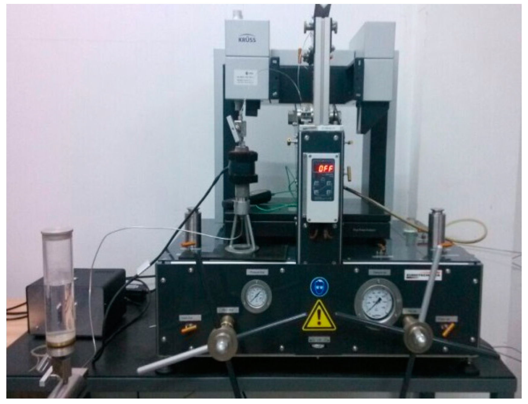
2.1.2. Experimental Instrument
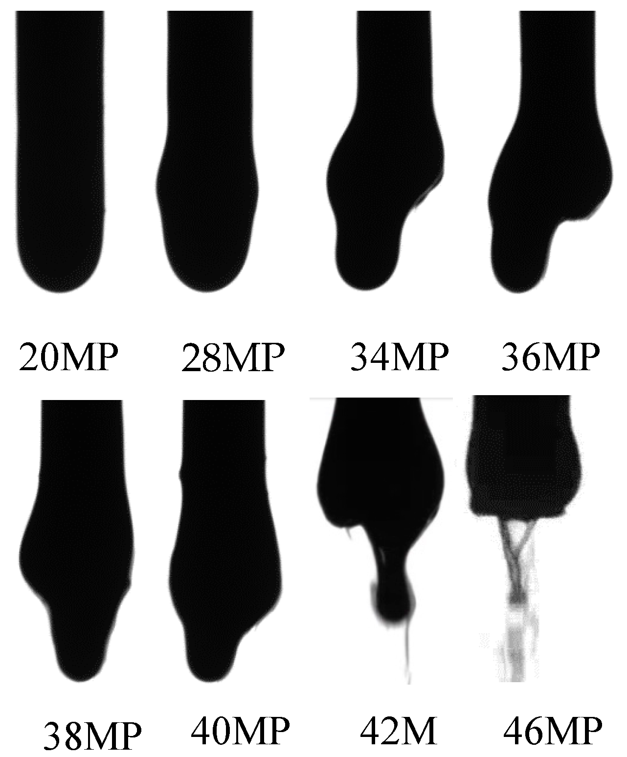
2.1.3. Experimental Procedures
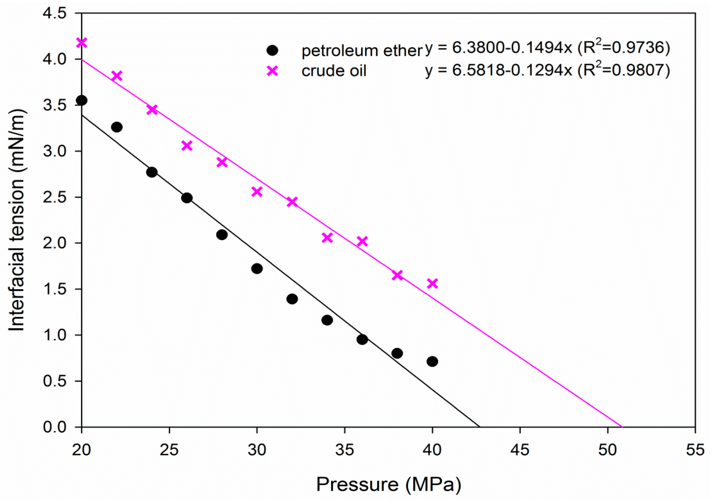
2.2. Experimental Results
2.3. Discussions
3. Screening and Evaluation of Hydrocarbon Agents
3.1. Influence of Hydrocarbon Agents on CO2–Oil IFT and MMP
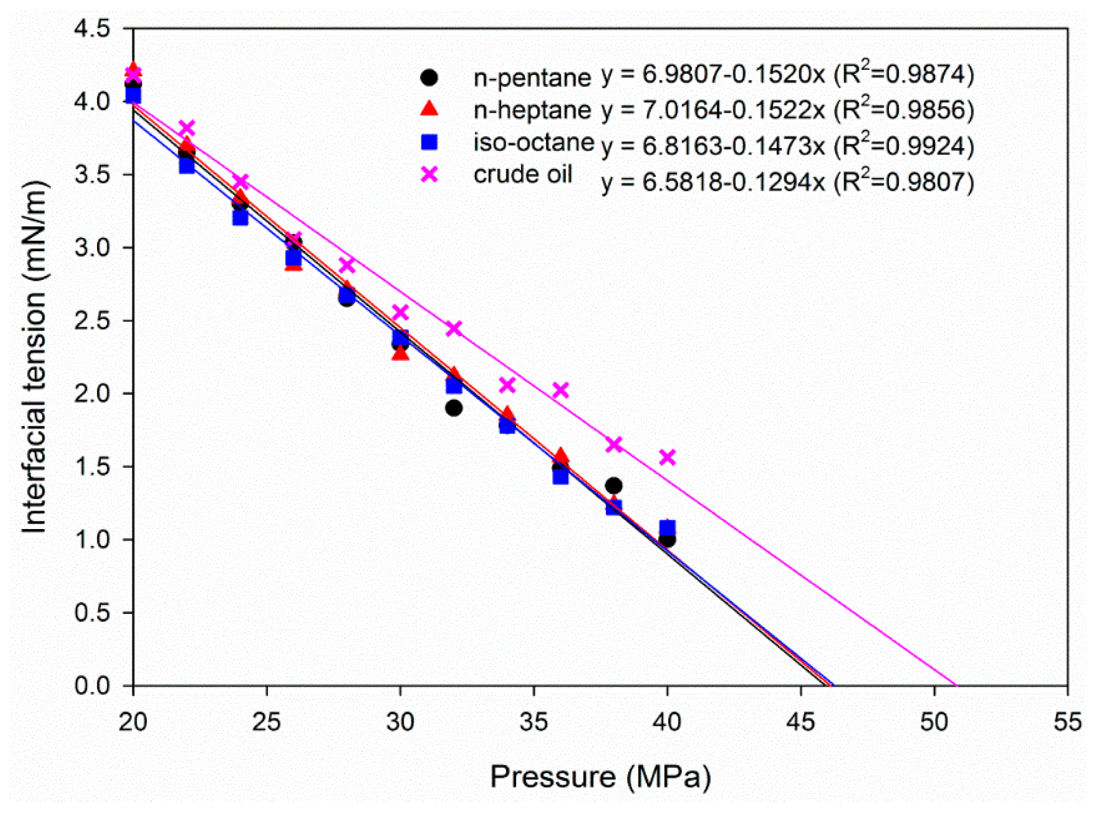
3.1.1. Alkane Type
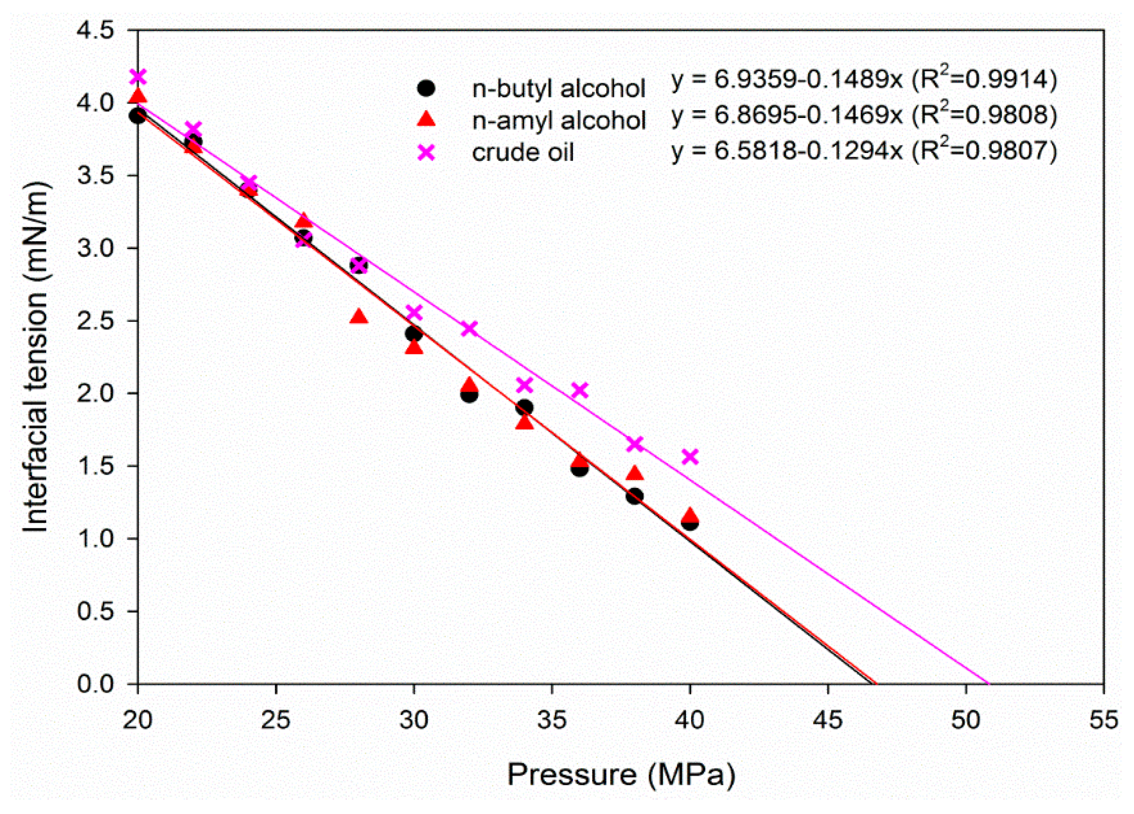
3.1.2. Alcohol Type
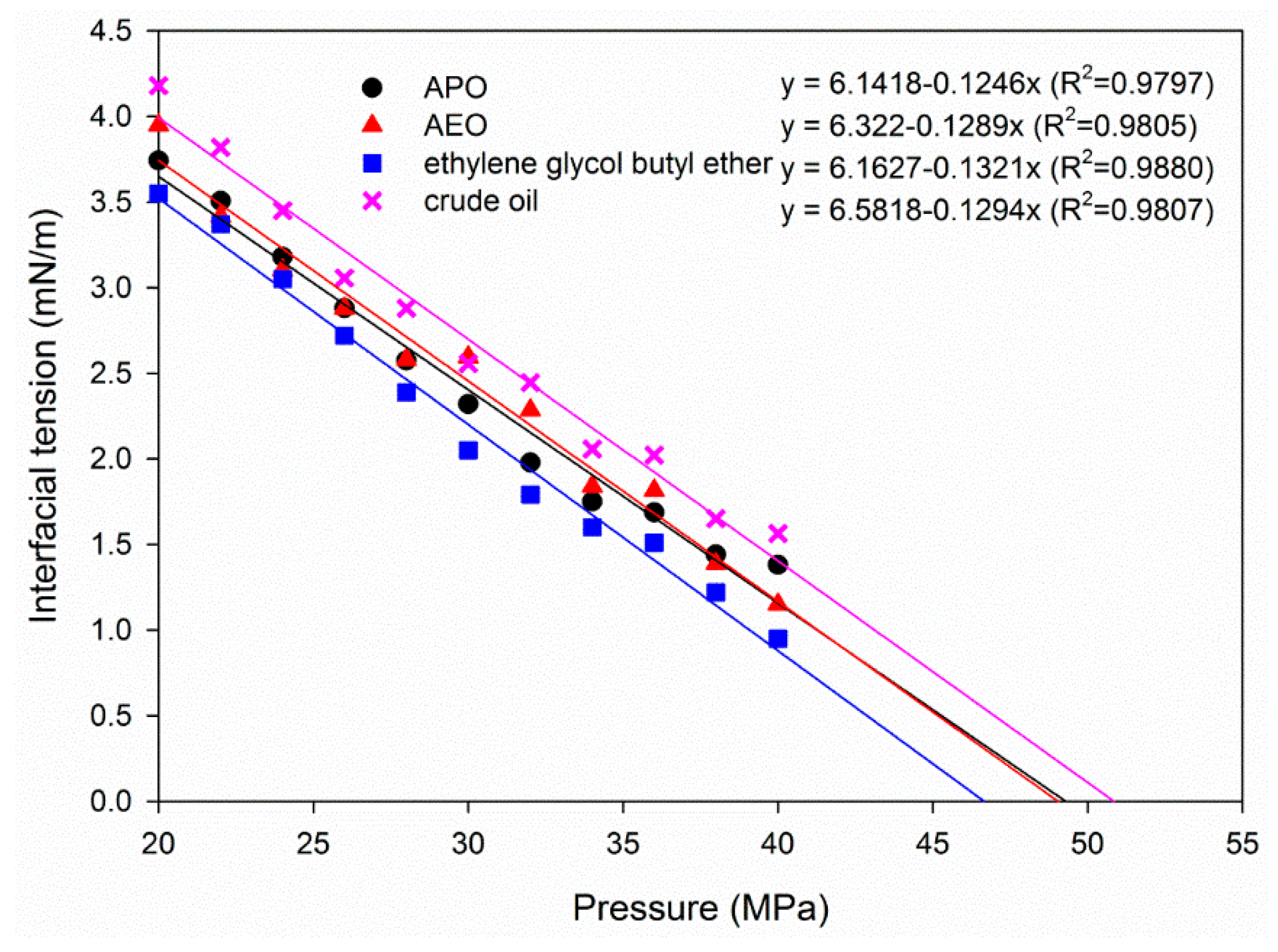
3.1.3. Oil-Soluble Surfactant Type
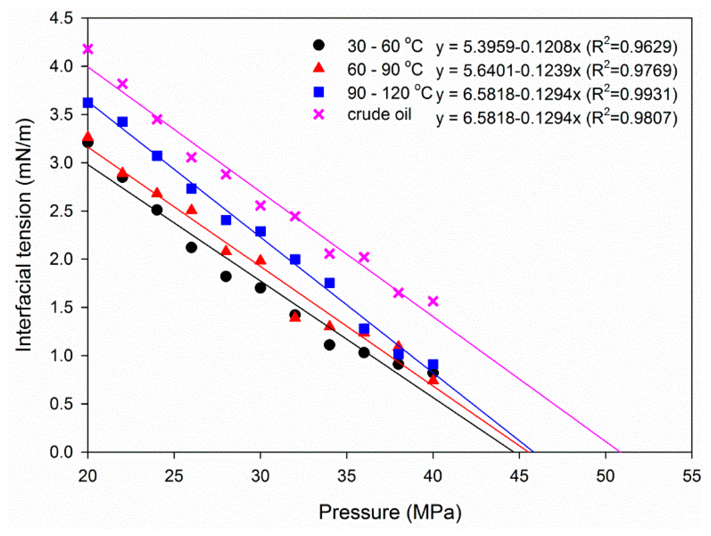
3.1.4. Petroleum Ether Type
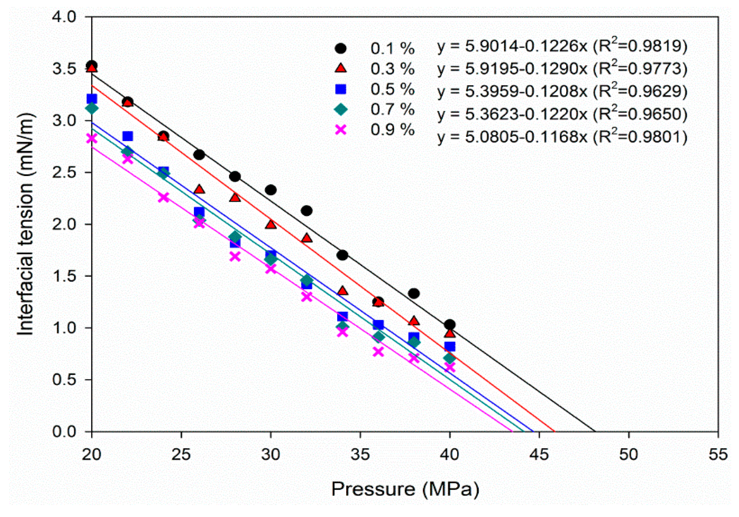
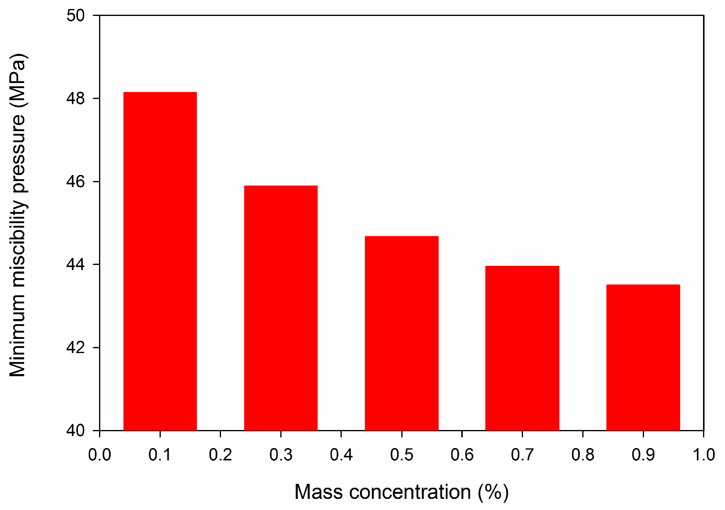
3.2. Influence of Mass Concentration of Petroleum Ether on CO2–Oil Interfacial Tension and Miscibility Pressure
3.3. Influence of Hydrocarbon Agents on Crude Oil Viscosity
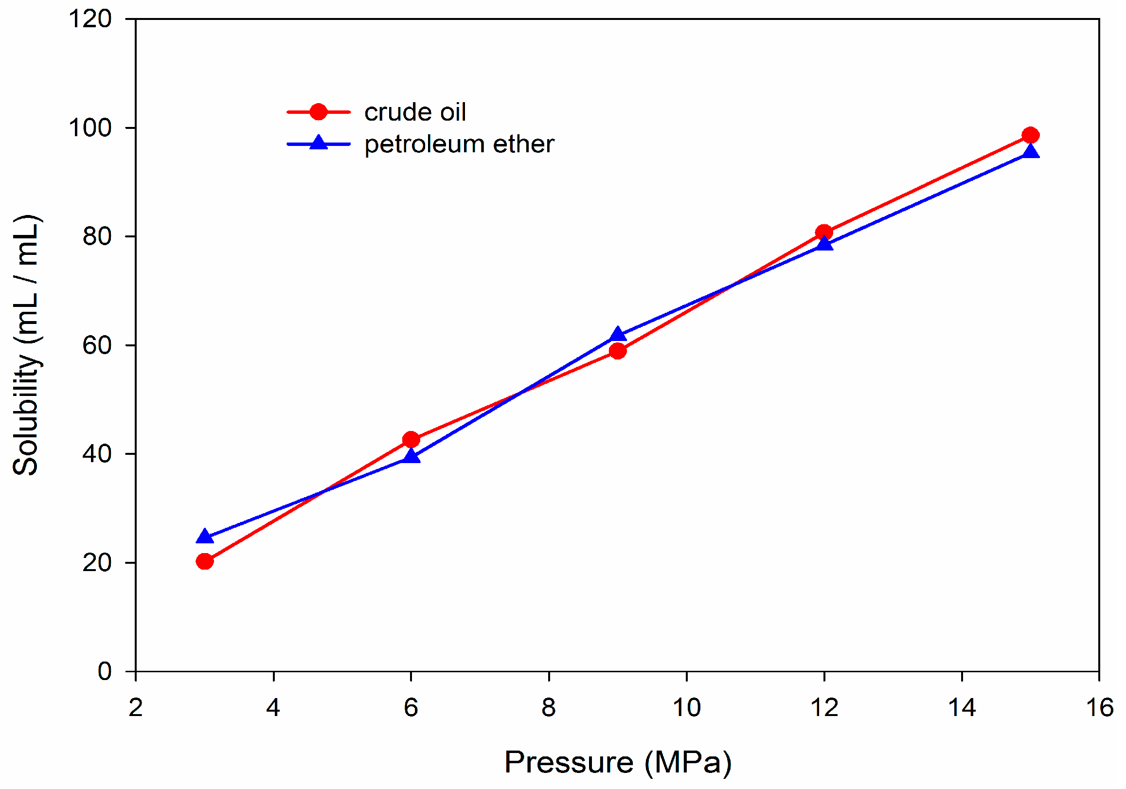
3.4. Influence of Hydrocarbon Agents on Injectivity
4. Conclusions
Author Contributions
Funding
Conflicts of Interest
References
- Verma, M.K. Fundamentals of Carbon Dioxide-Enhanced Oil Recovery (CO2-EOR): A Supporting Document of the Assessment Methodology for Hydrocarbon Recovery using CO2-EOR Associated with Carbon Sequestration; US Department of the Interior: Washington, DC, USA, 2015.
- NETL US Department of Energy. Enhanced Oil Recovery. Available online: https://www.energy.gov/fe/science-innovation/oil-gas-research/enhanced–oil-recovery (accessed on 9 April 2019).
- Glaso, O. Generalized minimum miscibility pressure correlation (includes associated papers 15845 and 16287). Soc. Pet. Eng. J. 1985, 25, 927–934. [Google Scholar] [CrossRef]
- Orr, F., Jr.; Yu, A.; Lien, C. Phase behavior of CO2 and crude oil in low-temperature reservoirs. Soc. Pet. Eng. J. 1981, 21, 480–492. [Google Scholar] [CrossRef]
- National Energy Technology Laboratory (NETL). Recovery, Carbon Dioxide Enhanced Oil, Untapped Domestic Energy Supply and Long Term Carbon Storage Solution; National Energy Technology Laboratory (NETL), US Department of Energy: Washington, DC, USA, 2010.
- Li, S.L.; Guo, P.; Dai, L.; Sun, L. Strengthen gas injection for enhanced oil recovery. J. Southwest Pet. Inst. 2000, 22, 41–45. [Google Scholar]
- Shen, P.P.; Jiang, H.Y.; Che, Y.W.; Li, Y.T.; Liu, J.S. EOR study of CO2 injection. SPEC Oil Gas Reserv. 2007, 14, 1–4. [Google Scholar]
- Li, B.F.; Ye, J.Q.; Li, Z.M.; Ji, Y.M.; Liu, W. Phase interaction of CO2–oil-water system and its effect on interfacical tension at high temperature and high pressure. Acta Pet. Sin. 2016, 37, 1265–1272. [Google Scholar]
- Han, H.S.; Li, S.; Chen, X.L.; Qin, J.S.; Zeng, B.Q. Main control factors of carbon dioxide on swelling effect of crude hydrocarbon components. Acta Pet. Sin. 2016, 37, 392–398. [Google Scholar]
- Tang, M.M.; Zhao, H.Y.; Ma, H.F.; Lu, S.F.; Chen, Y.M. Study on CO2 huff-n-puff of horizontal wells in continental tight oil reservoirs. Fuel 2017, 188, 140–154. [Google Scholar] [CrossRef]
- Peng, X.Y.; Wang, Y.Y.; Diao, Y.Q.; Zhang, L.; Yazid, I.M.; Ren, S.R. Experimental investigation on the operation parameters of carbon dioxide huff-n-puff process in ultra low permeability oil reservoirs. J. Pet. Sci. Eng. 2019, 174, 903–912. [Google Scholar] [CrossRef]
- Li, L.; Zhang, Y.; Sheng, J.J. Effect of the Injection Pressure on Enhancing Oil Recovery in Shale Cores during the CO2 Huff-n-Puff Process When It Is above and below the Minimum Miscibility Pressure. Energy Fuels 2017, 31, 3856–3867. [Google Scholar] [CrossRef]
- Zuloaga, P.; Yu, W.; Miao, J.J.; Sepehrnoori, K. Performance evaluation of CO2 Huff-n-Puff and continuous CO2 injection in tight oil reservoirs. Energy 2017, 134, 181–192. [Google Scholar] [CrossRef]
- Fox, M.J.; Simlote, V.N.; Beaty, W.G. Evaluation Of CO2 Flood Performance; Springer: Garvin County, NE, USA, 1984. [Google Scholar]
- Martin, F.D. Carbon dioxide flooding. J. Can. Pet. Technol. 1992, 44, 396–400. [Google Scholar] [CrossRef]
- Langston, M.V.; Hoadley, S.F.; Young, D.N. Definitive CO2 Flooding Response in the SACROC Unit. In Proceedings of the SPE Enhanced Oil Recovery Symposium, Tulsa, OA, USA, 16–21 April 1988. [Google Scholar]
- Koottungal, L. 2004 worldwide EOR survey. Oil Gas J. 2004, 102, 53–65. [Google Scholar]
- Koottungal, L. 2006 worldwide EOR survey. Oil Gas J. 2006, 104, 45–57. [Google Scholar]
- Koottungal, L. 2008 worldwide EOR survey. Oil Gas J. 2008, 106, 47–59. [Google Scholar]
- Koottungal, L. 2010 worldwide EOR survey. Oil Gas J. 2010, 108, 41–53. [Google Scholar]
- Koottungal, L. 2012 worldwide EOR survey. Oil Gas J. 2012, 110, 57–69. [Google Scholar]
- Koottungal, L. 2014 worldwide EOR survey. Oil Gas J. 2014, 112, 79–91. [Google Scholar]
- Welkenhuysen, K.; Meyvis, B.; Piessens, K. A Profitability Study of CO2-EOR and Subsequent CO2 Storage in the North Sea under Low Oil Market Prices. Energy Procedia 2017, 114, 7060–7069. [Google Scholar] [CrossRef]
- Welkenhuysen, K.; Meyvis, B.; Swennen, R.; Piessens, K. Economic threshold of CO2-EOR and CO2 storage in the North Sea: A case study of the Claymore, Scott and Buzzard oil fields. Int. J. Greenh. Gas Control 2018, 78, 271–285. [Google Scholar] [CrossRef]
- Cavanagh, A.; Ringrose, P. Improving Oil Recovery and Enabling CCS: A Comparison of Offshore Gas-recycling in Europe to CCUS in North America. Energy Procedia 2014, 63, 7677–7684. [Google Scholar] [CrossRef]
- Fleten, S.-E.; Lien, K.; Ljønes, K.; Pagès-Bernaus, A.; Aaberg, M. Value chains for carbon storage and enhanced oil recovery: Optimal investment under uncertainty. Energy Syst. 2010, 1, 457–470. [Google Scholar] [CrossRef][Green Version]
- Guo, D.B.; Fang, Q.; Nie, F.J. Study on EOR of injection CO2 for waterflooding abandoned reservoir. Fault Block Oil Gas Field 2012, 19, 187–190. [Google Scholar]
- Zhang, J.; Zhou, Z.W.; Wang, W.S.; Tao, L.B. EOR field test of gas-water alternative injection in Pubei oilfield. Pet. Explor. Dev. 2004, 31, 85–87. [Google Scholar]
- Hao, Y.M.; Chen, Y.M.; Ying, H.L. Determination and prediction of minimum miscibility pressure in CO2 flooding. Pet. Geol. Recovery Effic. 2005, 12, 64–66. [Google Scholar]
- Ju, B.S.; Qin, J.S.; Li, Z.P.; Chen, X. A prediction model for the minumum miscibility pressure of the CO2-crude oil system. Acta Pet. Sin. 2012, 33, 274–277. [Google Scholar]
- Bon, J.; Sarma, H.K.; Theophilos, A.M. An Investigation of Minimum Miscibility Pressure for CO2—Rich Injection Gases with Pentanes-Plus Fraction. In Proceedings of the SPE International Improved Oil Recovery Conference in Asia Pacific, Kuala Lumpur, Malaysia, 5–6 December 2005. [Google Scholar]
- Liu, Y.; Jiang, L.L.; Song, Y.C.; Zhao, Y.C.; Zhang, Y.; Wang, D.Y. Estimation of minimum miscibility pressure (MMP) of CO2 and liquid n-alkane systems using an improved MRI technique. Magn. Reson. Imaging 2016, 34, 97–104. [Google Scholar] [CrossRef]
- Guo, P.; Li, M. A study on the miscible conditions of CO2 injection in low-permeability sandstone reservoirs. Oil Gas Geol. 2007, 28, 687–690. [Google Scholar]
- Yao, Y.D.; Wang, Z.J.; Li, G.Z.; Wu, H.; Wang, J.N. Potential of carbon dioxide miscible injections into the H-26 reservoir. J. Nat. Gas Sci. Eng. 2016, 34, 1085–1095. [Google Scholar] [CrossRef]
- Kaydani, H.; Najafzadeh, M.; Hajizadeh, A. A new correlation for calculating carbon dioxide minimum miscibility pressure based on multi-gene genetic programming. J. Nat. Gas Sci. Eng. 2014, 21, 625–630. [Google Scholar] [CrossRef]
- Chen, G.Y.; Gao, H.X.; Fu, K.Y.; Zhang, H.Y.; Liang, Z.W.; Tontiwachwuthikul, P. An improved correlation to determine minimum miscibility pressure of CO2–oil system. Green Energy Environ. 2018. [Google Scholar] [CrossRef]
- Christiansen, R.L.; Haines, H.K. Rapid Measurement of Minimum Miscibility Pressure With the Rising-Bubble Apparatus. SPE Reserv. Eng. 1987, 2, 523–527. [Google Scholar] [CrossRef]
- Zhou, D.; Orr, F.M., Jr. An Analysis of Rising Bubble Experiments to Determine Minimum Miscibility Pressures. SPE J. 1988, 3, 19–25. [Google Scholar] [CrossRef]
- Nobakht, M.; Moghadam, S.e.; Gu, Y.A. Determination of CO2 Minimum Miscibility Pressure from Measured and Predicted Equilibrium Interfacial Tensions. Ind. Eng. Chem. Res. 2008, 47, 8918–8925. [Google Scholar] [CrossRef]
- Rao, D.N.; Lee, J.I. Application of the new vanishing interfacial tension technique to evaluate miscibility conditions for the Terra Nova Offshore Project. J. Pet. Sci. Eng. 2002, 35, 247–262. [Google Scholar] [CrossRef]
- Wu, R.S.; Batycky, J.P. Evaluation Of Miscibility From Slim Tube Tests. J. Can. Pet. Technol. 1990, 29, 9. [Google Scholar] [CrossRef]
- Czarnota, R.; Janiga, D.; Stopa, J.; Wojnarowski, P. Determination of minimum miscibility pressure for CO2 and oil system using acoustically monitored separator. J. CO2 Util. 2017, 17, 32–36. [Google Scholar] [CrossRef]
- Mihcakan, M. Minimum Miscibility Pressure, Rising Bubble Apparatus, and Phase Behavior. In Proceedings of the SPE/DOE Improved Oil Recovery Symposium, Tulsa, OA, USA, 17–20 April 1994. [Google Scholar]
- Rao, D.N. A new technique of vanishing interfacial tension for miscibility determination. Fluid Phase Equilib. 1997, 139, 311–324. [Google Scholar] [CrossRef]
- Andreas, J.H.; Hauser, E.A.; Tucker, W.B. Boundary tension by pendant drops. J. Phys. Chem. 1938, 42, 1001–1019. [Google Scholar] [CrossRef]
- Peng, B.Z.; Luo, H.; Chen, G.J.; Sun, C.Y. Determination of the minimum miscibility pressure of CO2 and crude oil system by vanishing interfacial tension method. Acta Pet. Sin. 2007, 28, 93–95. [Google Scholar]
- Luo, K.; Chen, G. Application of the Gas-Oil Interfacial Tension to Determine Minimum Miscibility Pressure. In Proceedings of the Canadian International Petroleum Conference, Calgary, AL, Canada, 17–19 June 2001. [Google Scholar]
- Wang, H.Z.; Shen, Z.H.; Li, G.S. Feasibility analysis on shale gas exploitation with supercritical CO2. Pet. Drill. Tech. 2011, 39, 30–34. [Google Scholar]
- Czarnota, R.; Janiga, D.; Stopa, J.; Wojnarowski, P. Acoustic investigation of CO2 mass transfer into oil phase for vapor extraction process under reservoir conditions. Int. J. Heat Mass Transf. 2018, 127, 430–437. [Google Scholar] [CrossRef]
- Rudyk, S.; Spirov, P.; Tyrovolas, A. Effect of temperature on crude oil extraction by SC-CO2 at 40–70 °C and 40–60 MPa. J. CO2 Util. 2018, 24, 471–478. [Google Scholar] [CrossRef]
- Li, H.Z.; Zheng, S.X.; Yang, D.Y. Enhanced Swelling Effect and Viscosity Reduction of Solvents-CO2-Heavy Oil Systems. In Proceedings of the SPE Heavy Oil Conference and Exhibition, Kuwait City, Kuwait, 12–14 December 2011. [Google Scholar]
- Bon, J.; Sarma, H.K. A Technical Evaluation of a CO2 Flood for EOR Benefits in the Cooper Basin, South Australia. In Proceedings of the SPE Asia Pacific Oil and Gas Conference and Exhibition, Perth, Australia, 18–20 October 2004. [Google Scholar]
- Deng, R.J.; Qi, G.X.; Tan, X.; Li, P.C. Influence of hydrocarbon components on the minimum miscibility pressure of CO2 flooding. Chem. Eng. Oil Gas 2018, 47, 59–63. [Google Scholar] [CrossRef]
- Shi, J.P.; Shao, X.Q.; Ma, J.H.; Zhang, X.L.; Yang, X.D.; Cao, W.Z. Application of experimentally determined minimum starting pressure gradient of low permeability reservoir. Pet. Geol. Oilfield Dev. Daqing 2010, 29, 81–83. [Google Scholar] [CrossRef]


| Components | C1–C4 | C5‒C8 | C9‒C12 | C13‒C18 | C19‒C22 | C23‒C27 | C28+ |
|---|---|---|---|---|---|---|---|
| Mole fraction (%) | 0 | 14.972 | 10.067 | 28.737 | 13.778 | 15.918 | 16.529 |
| Pressure (MPa) | CO2–Oil Interfacial Tension (mN/m) | |
|---|---|---|
| with Petroleum Ether | without Petroleum Ether | |
| 20 | 3.55 | 4.18 |
| 22 | 3.26 | 3.82 |
| 24 | 2.77 | 3.45 |
| 26 | 2.49 | 3.06 |
| 28 | 2.09 | 2.88 |
| 30 | 1.72 | 2.56 |
| 32 | 1.39 | 2.45 |
| 34 | 1.16 | 2.06 |
| 36 | 0.95 | 2.02 |
| 38 | 0.80 | 1.65 |
| 40 | 0.71 | 1.56 |
| Temperature (°C) | Viscosity (mPa·s) | ||||
|---|---|---|---|---|---|
| Ethylene Glycol Butyl Ether | N-butyl Alcohol | Petroleum Ether | N-pentane | Crude Oil | |
| 40 | 88.5 | 58.5 | 70.5 | 49.8 | 76.4 |
| 50 | 17.6 | 14.2 | 15.1 | 15.2 | 17.4 |
| 60 | 10.5 | 10.2 | 10.8 | 9.8 | 12.8 |
| 70 | 7.4 | 7.7 | 8.7 | 8.6 | 9.8 |
| Mass concentration of petroleum ether (%) | 0.1 | 0.3 | 0.5 | 0.7 | 0.9 |
| Viscosity (mPa·s) | 10.5 | 9.5 | 8.7 | 8.2 | 7.9 |
| Q(mL/min) | Pressure Gradient (MPa/cm) | |||
|---|---|---|---|---|
| Ethylene Glycol Monobutyl Ether | N-butyl Alcohol | Petroleum Ether (30–60 °C) | N-pentane | |
| 0.05 | 0.187 | 0.125 | 0.086 | 0.087 |
| 0.10 | 0.290 | 0.191 | 0.155 | 0.151 |
| 0.20 | 0.412 | 0.289 | 0.242 | 0.252 |
| 0.30 | 0.554 | 0.427 | 0.351 | 0.343 |
© 2019 by the authors. Licensee MDPI, Basel, Switzerland. This article is an open access article distributed under the terms and conditions of the Creative Commons Attribution (CC BY) license (http://creativecommons.org/licenses/by/4.0/).
Share and Cite
Liu, J.; Sun, L.; Li, Z.; Wu, X. Experimental Study on Reducing CO2–Oil Minimum Miscibility Pressure with Hydrocarbon Agents. Energies 2019, 12, 1975. https://doi.org/10.3390/en12101975
Liu J, Sun L, Li Z, Wu X. Experimental Study on Reducing CO2–Oil Minimum Miscibility Pressure with Hydrocarbon Agents. Energies. 2019; 12(10):1975. https://doi.org/10.3390/en12101975
Chicago/Turabian StyleLiu, Junrong, Lu Sun, Zunzhao Li, and Xingru Wu. 2019. "Experimental Study on Reducing CO2–Oil Minimum Miscibility Pressure with Hydrocarbon Agents" Energies 12, no. 10: 1975. https://doi.org/10.3390/en12101975
APA StyleLiu, J., Sun, L., Li, Z., & Wu, X. (2019). Experimental Study on Reducing CO2–Oil Minimum Miscibility Pressure with Hydrocarbon Agents. Energies, 12(10), 1975. https://doi.org/10.3390/en12101975