Effect of Zonal Hydraulics on Energy Consumption and Boom Structure of a Micro-Excavator


Abstract
1. Introduction
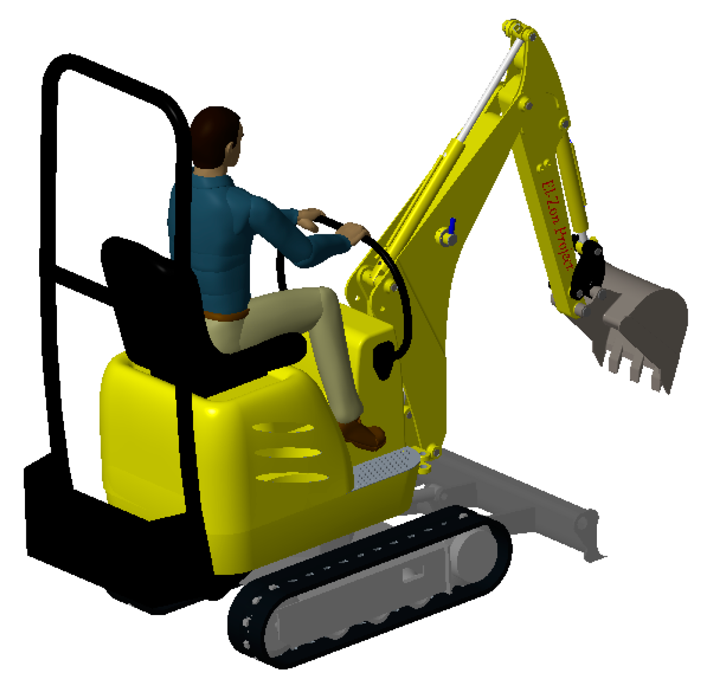
2. Test Case
2.1. Cycles
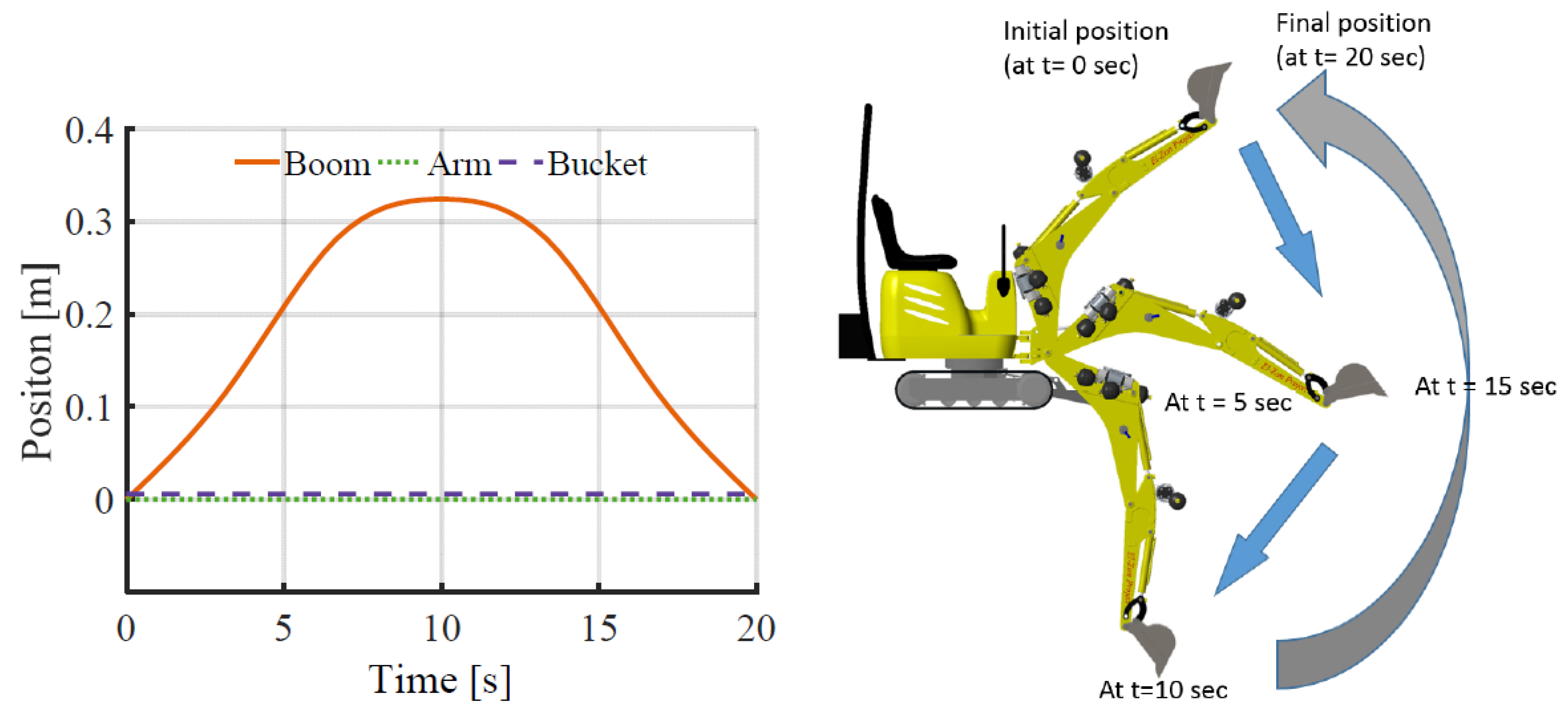
2.2. Extreme Cycle
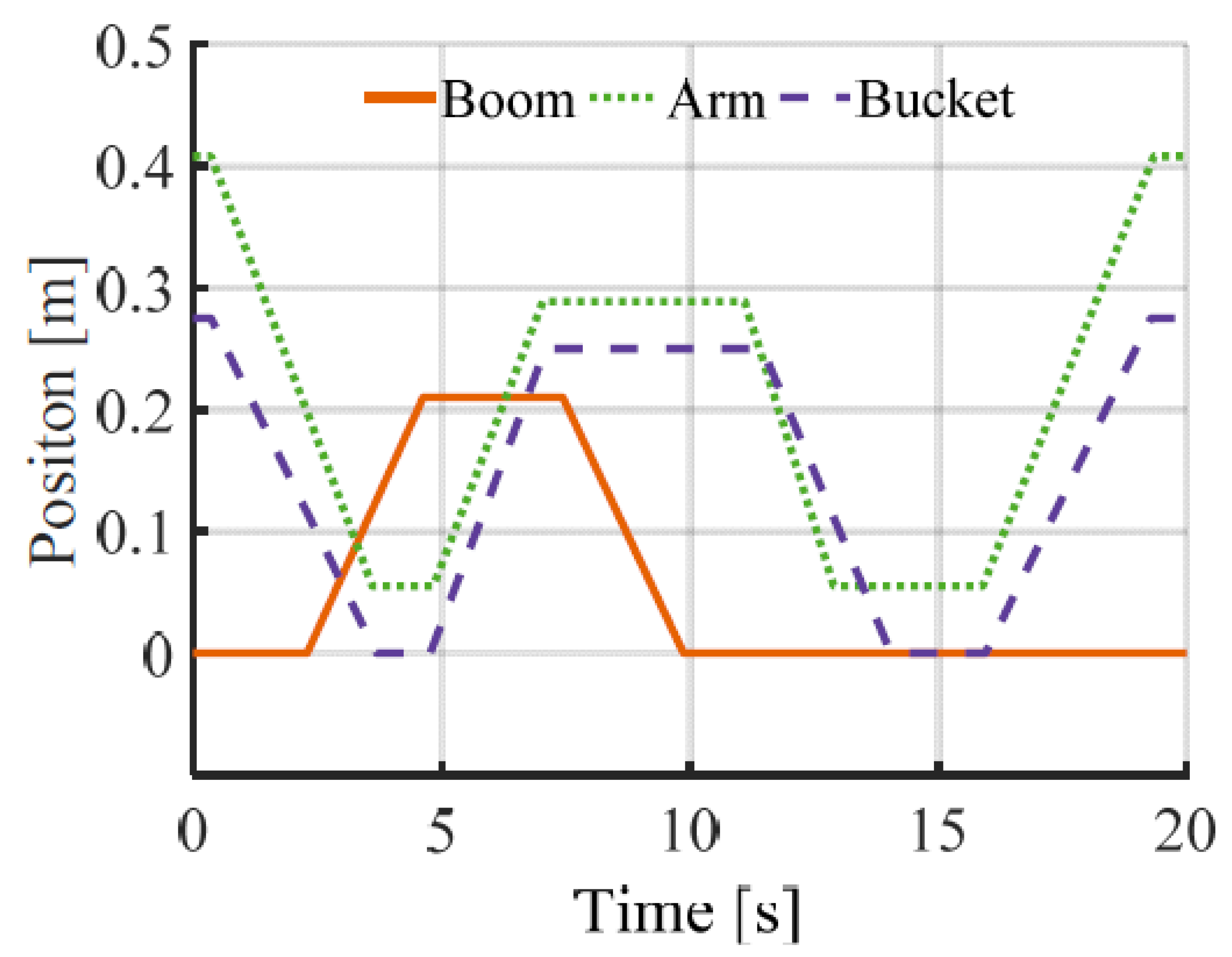
2.3. Typical Working Cycle
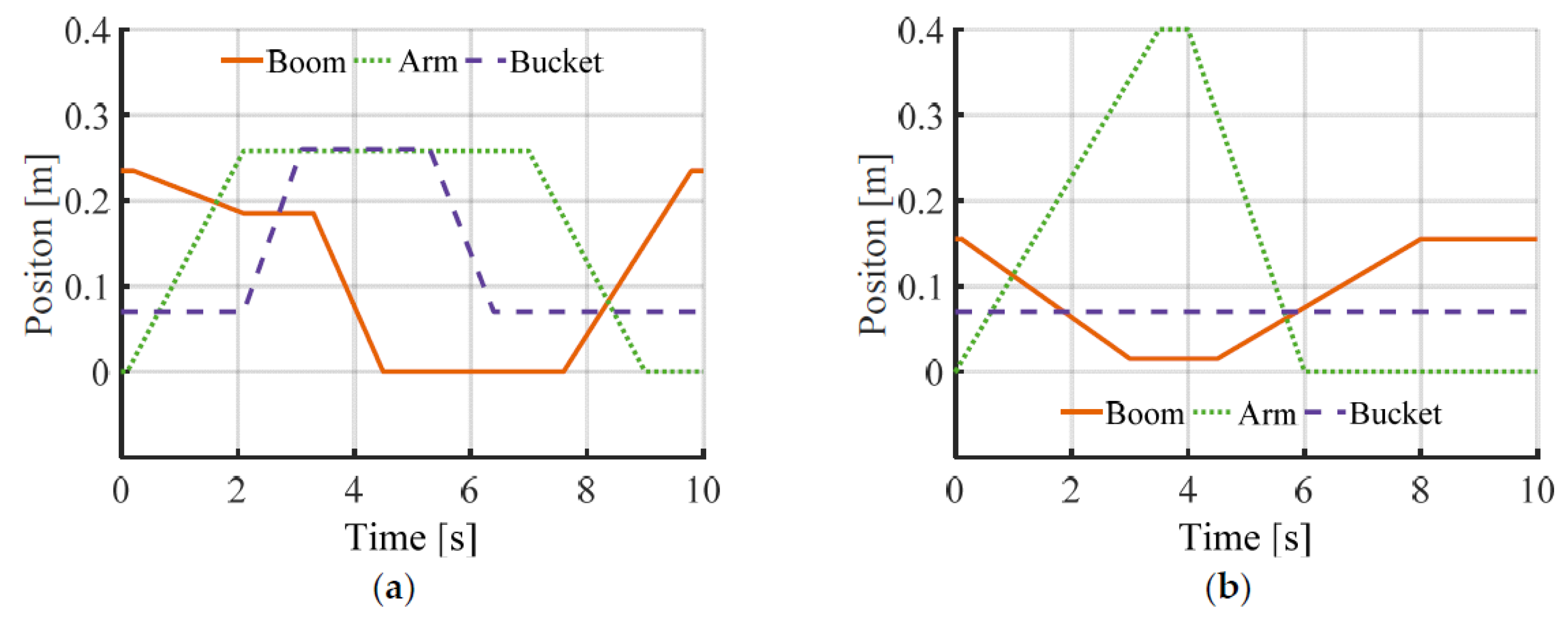
2.4. Modified Japanese Cycle
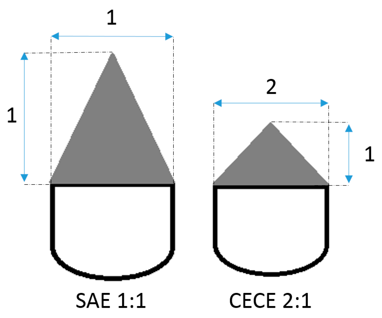
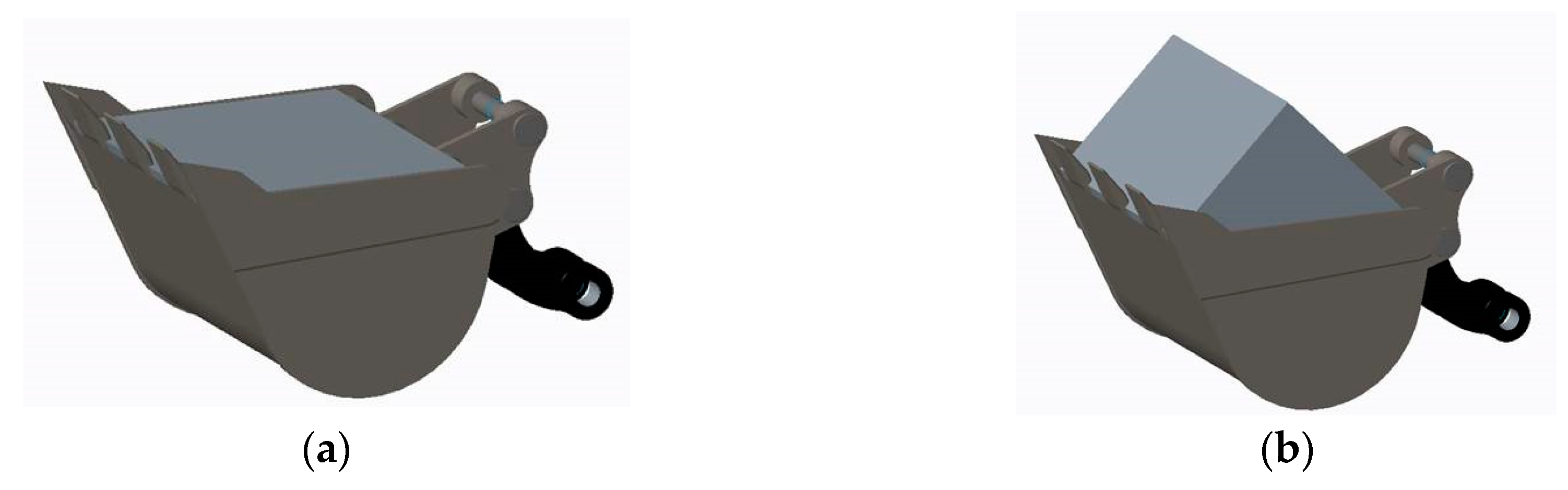
2.5. Payload
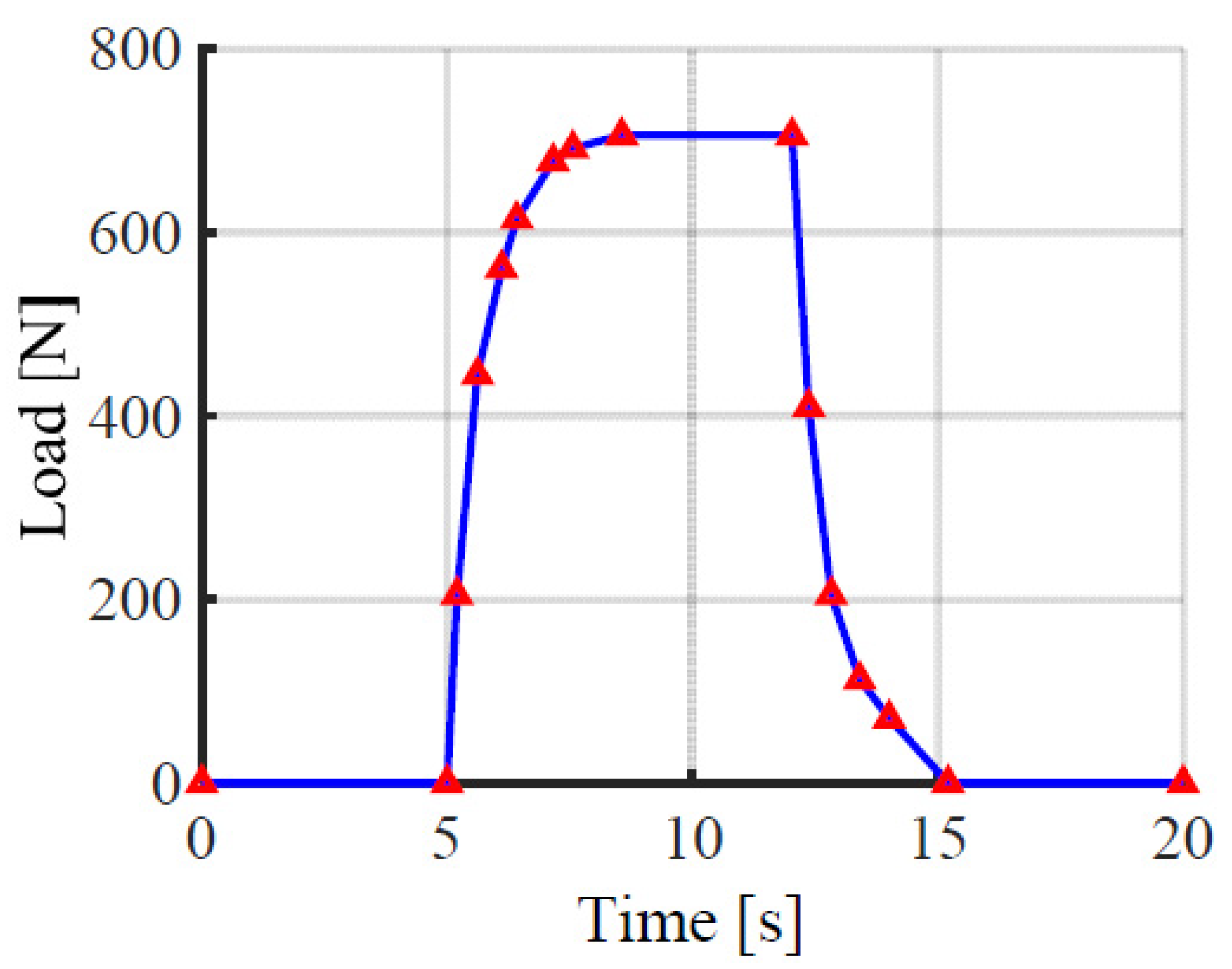
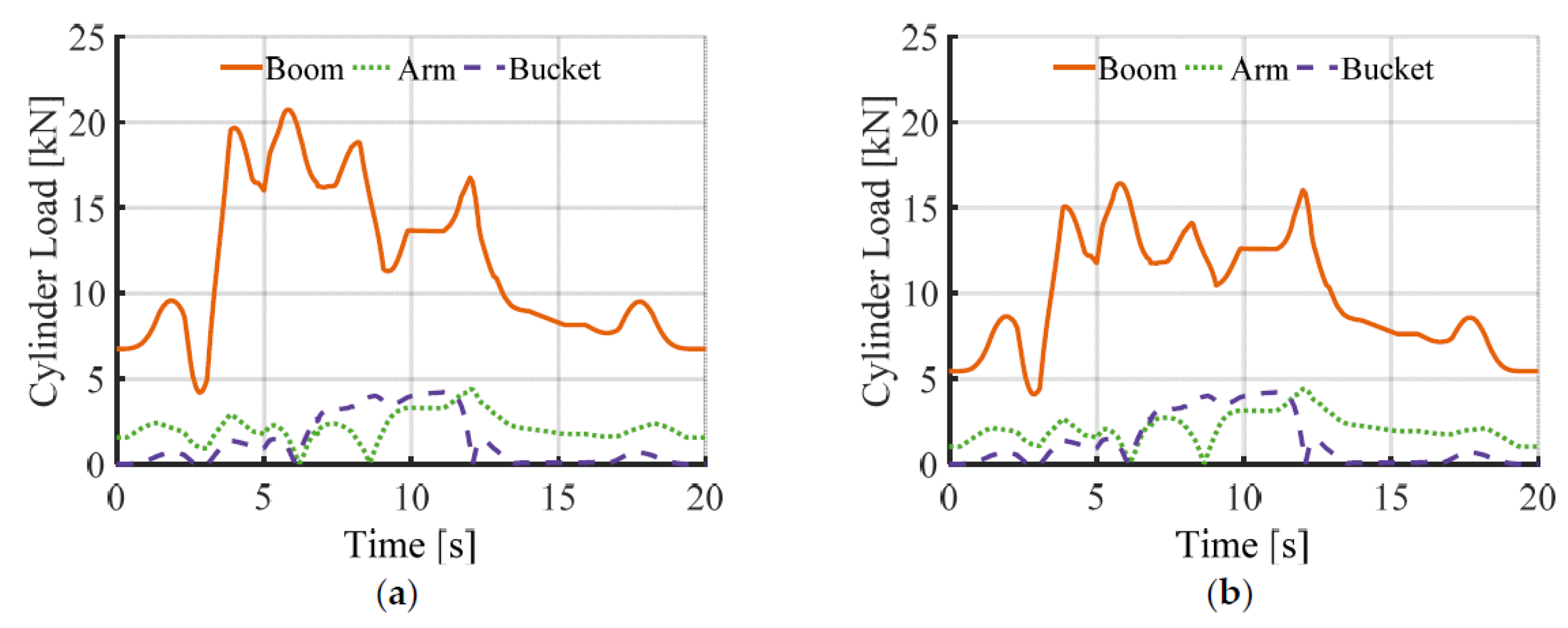
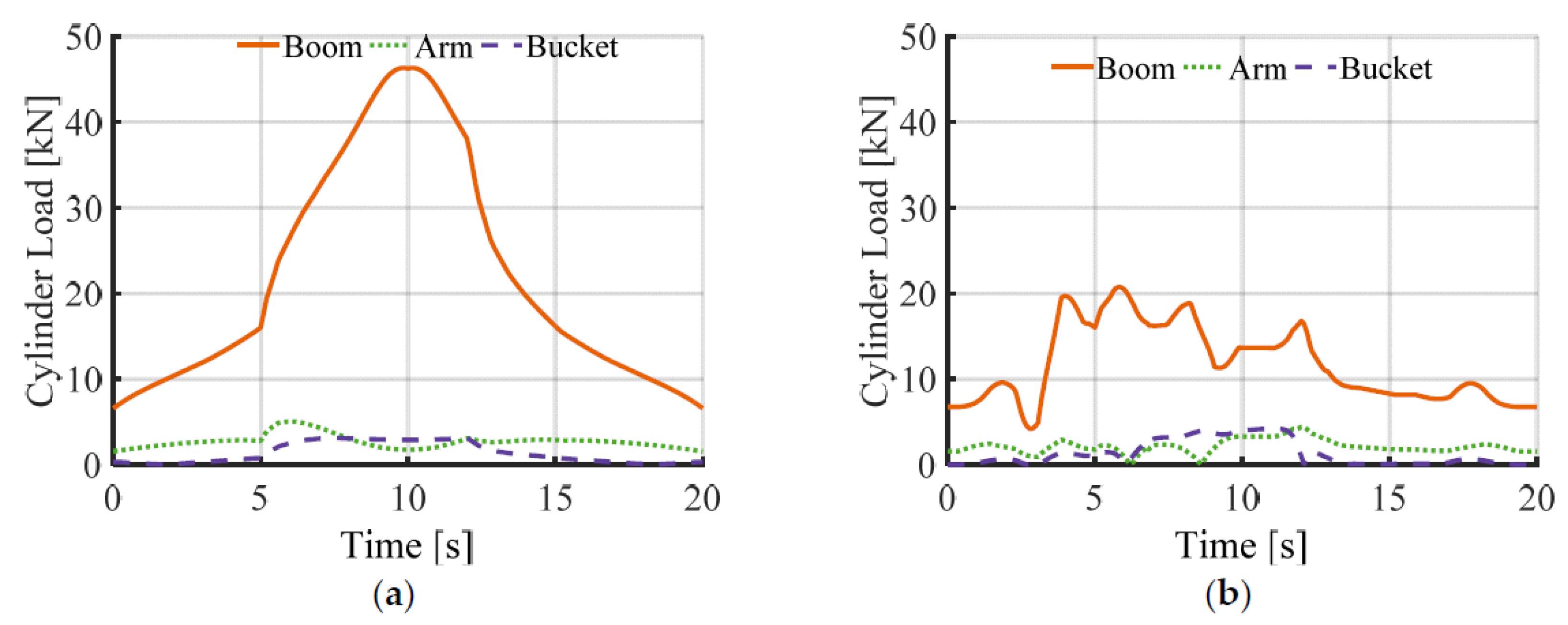
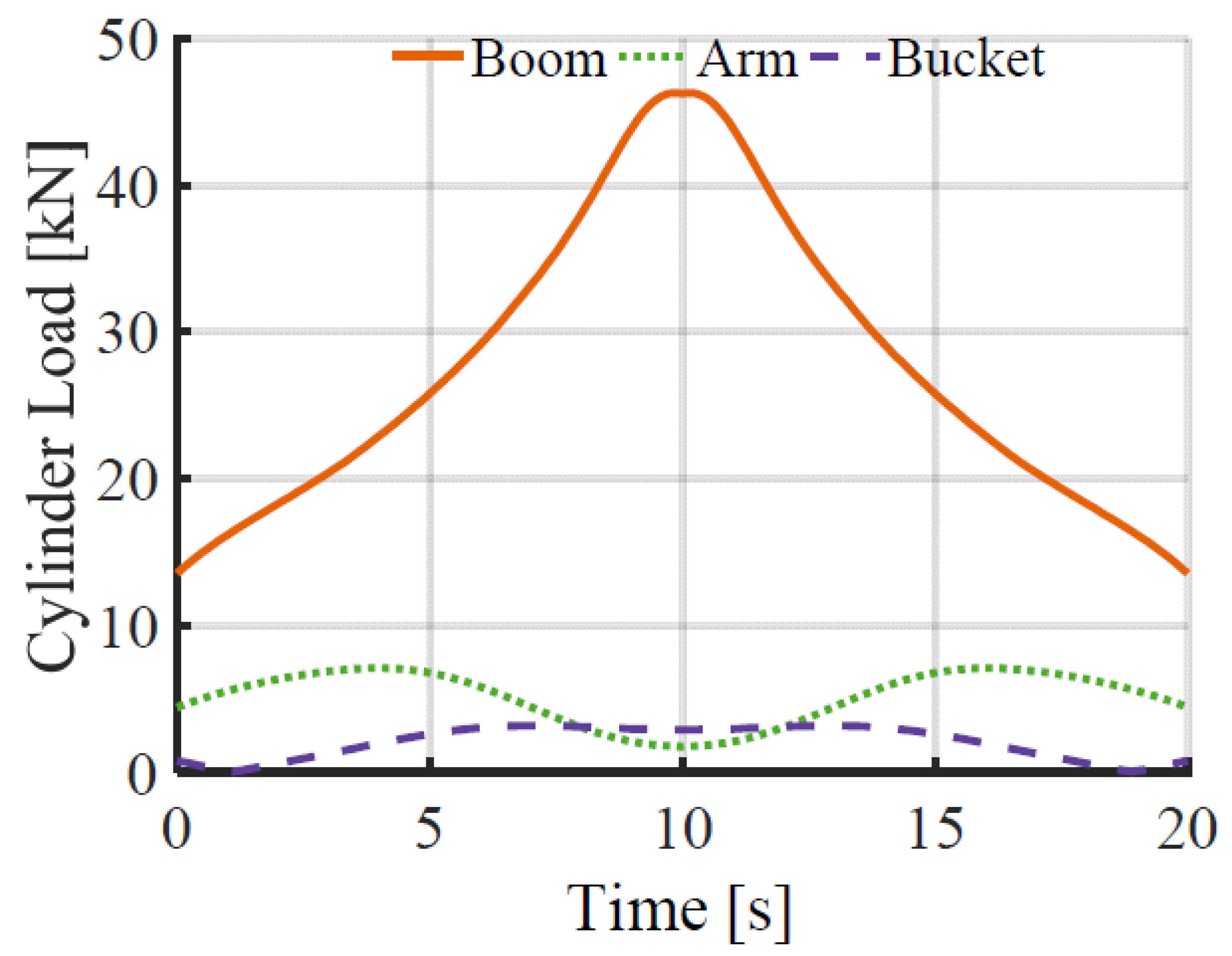
2.6. Digging Load Profile
3. Mechanical Analysis
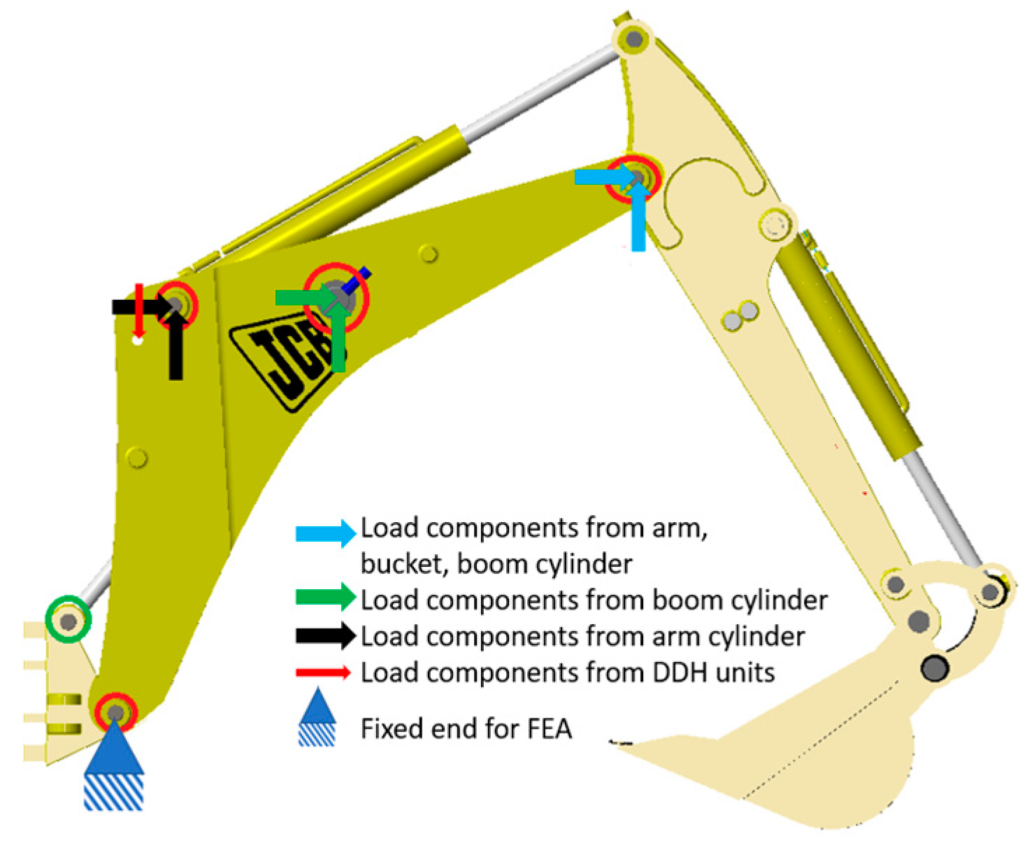
3.1. Determining the Critical Components for the Structural Analysis
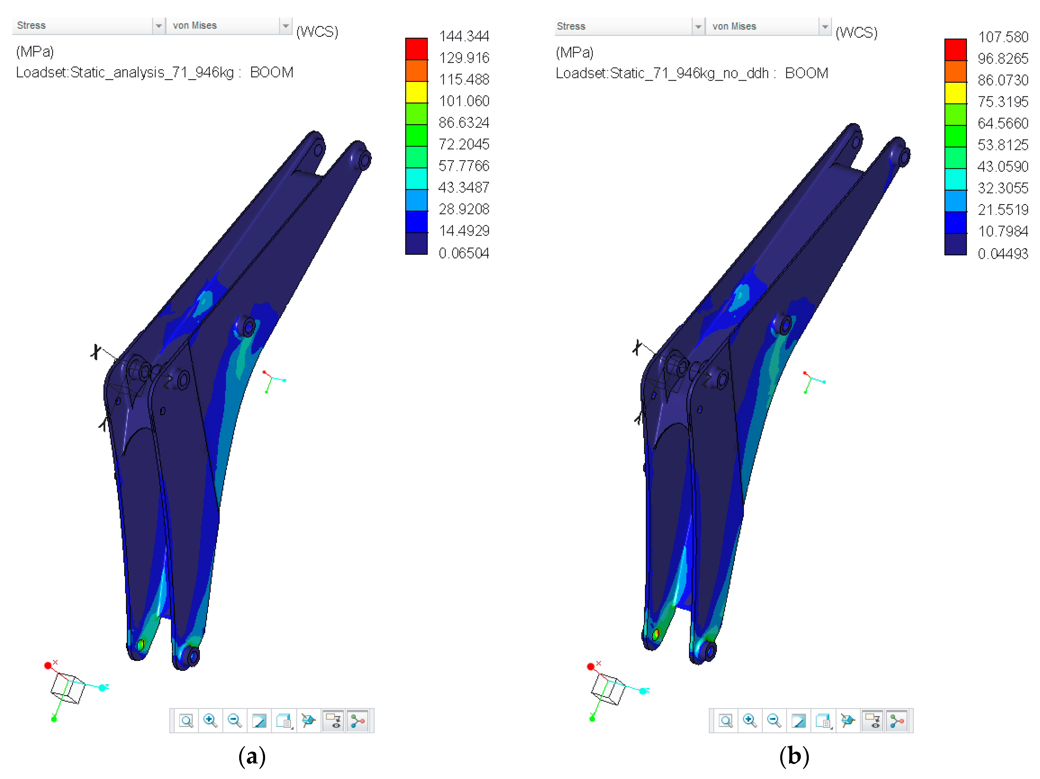
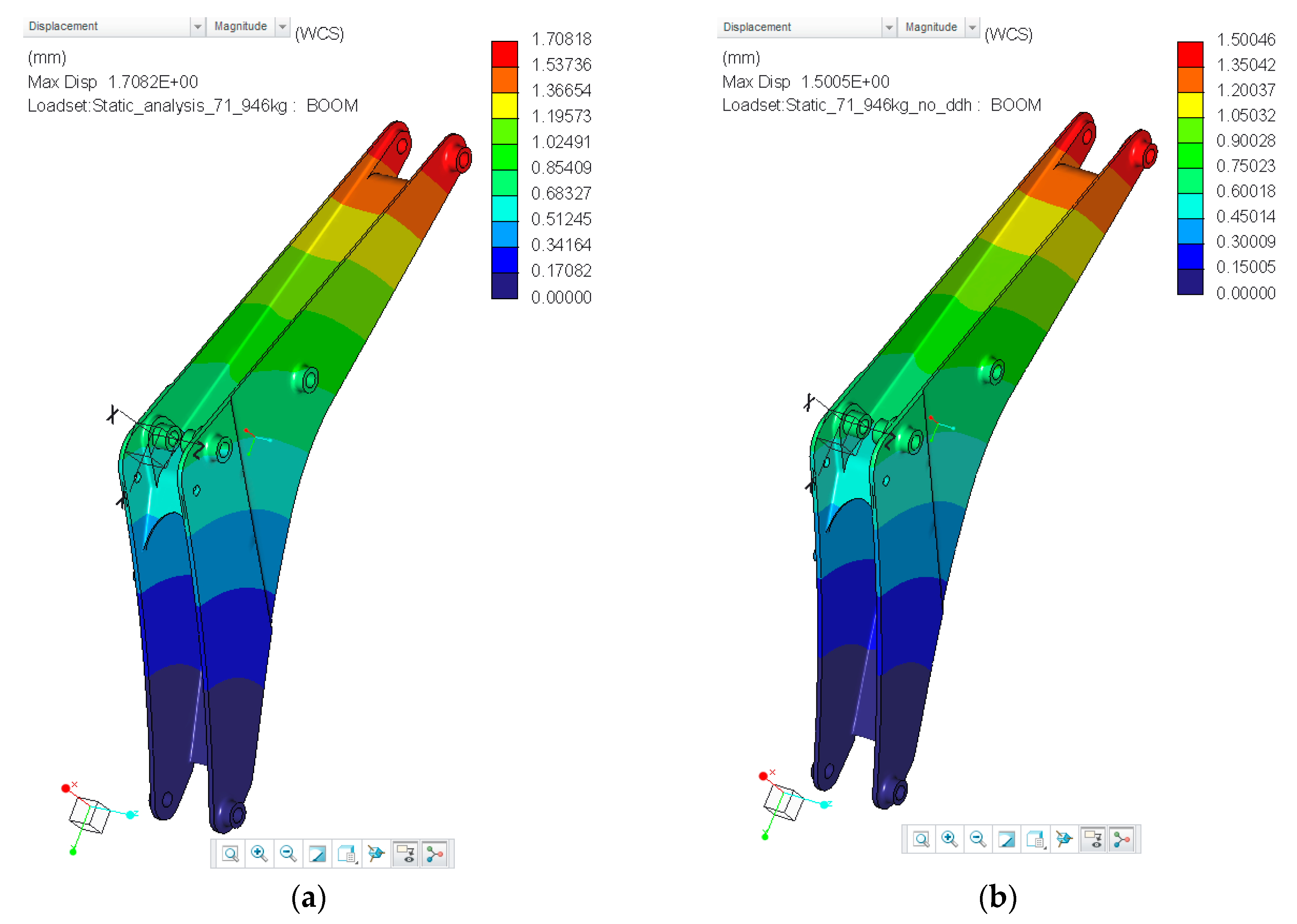
3.2. Structural Analysis
3.3. Finite Element Analysis (FEA)
4. Energy Consumption and Efficiency Analysis
4.1. Modelling
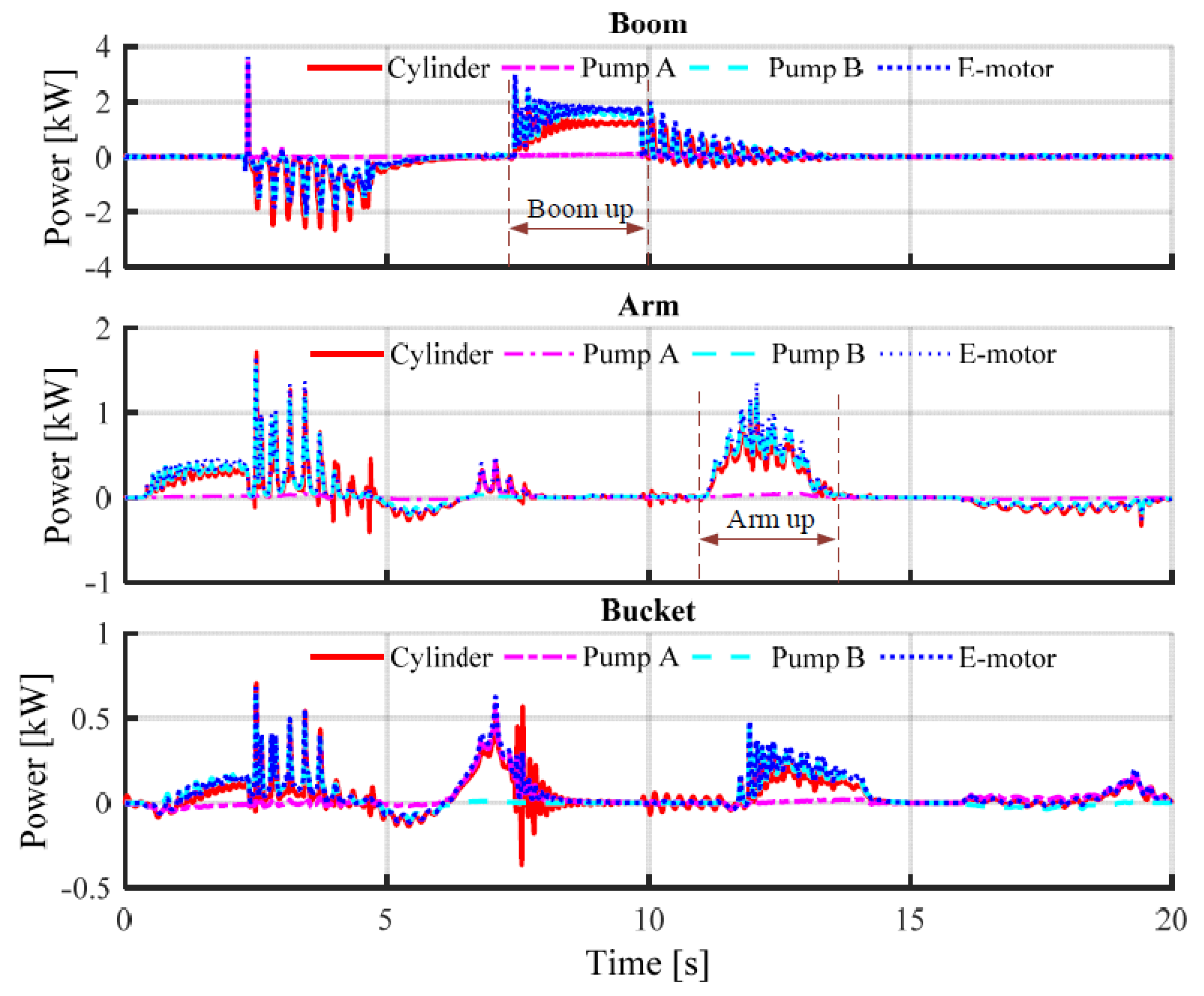
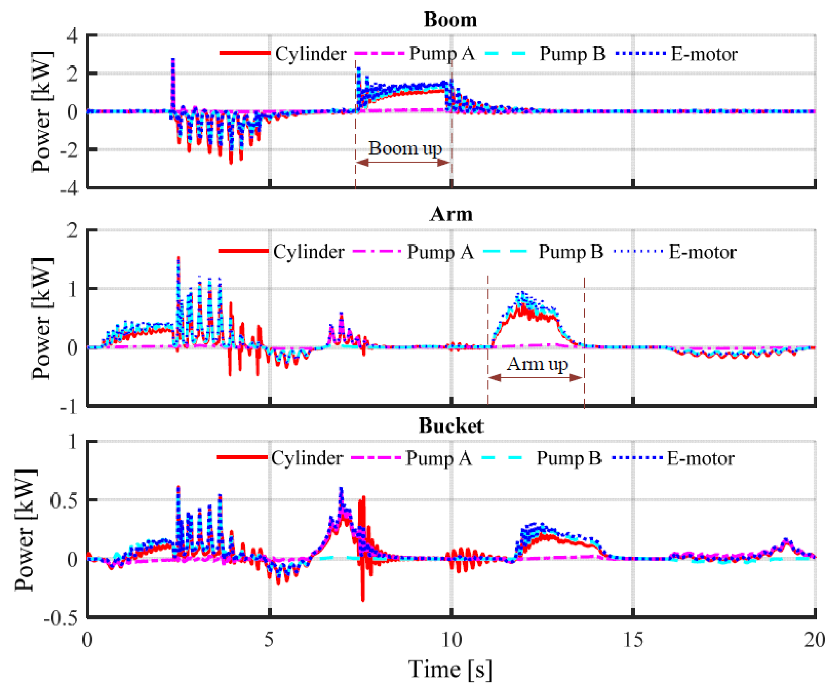
4.2. Results
5. Discussion and Future Outlook
5.1. Structural Analysis
5.2. Energy Consumption Analysis
6. Conclusions
Author Contributions
Funding
Conflicts of Interest
References
- A Roadmap for Heavy-Duty Engine CO2 Standards within the European Union Framework. September 2017. Available online: https://www.theicct.org/sites/default/files/publications/EU-HDV-CO2-engine-stds_ICCT-Briefing_04092017_vF.pdf (accessed on 5 January 2018).
- DieselNet. United States: Nonroad Diesel Engines, Tier 4 Emission Standards. Available online: https://www.dieselnet.com/standards/us/nonroad.php#tier4 (accessed on 8 March 2018).
- Casoli, P.; Riccò, L.; Campanini, F.; Bedotti, A. Hydraulic Hybrid Excavator—Mathematical Model Validation and Energy Analysis. Energies 2016, 9, 1002. [Google Scholar] [CrossRef]
- Lin, T.; Huang, W.; Ren, H.; Fu, S.; Liu, Q. New compound energy regeneration system and control strategy for hybrid hydraulic excavators. Autom. Constr. 2016, 68, 11–20. [Google Scholar] [CrossRef]
- Hassi, T.; Korva, A.; Markkula, S.; Partanen, T.; Sourander, T.; Kiviluoma, P.; Korhonen, A.; Kuosmanen, P. Improving Energy Efficiency of an Electric Mini Excavator. In Proceedings of the International DAAAM Baltic Industrial Engineering Conference, Tallinn, Estonia, 20–22 April 2016. [Google Scholar]
- Edamura, M.; Ishida, E.S.; Imura, S.; Izumi, S. Adoption of Electrification and Hybrid Drive for More Energy-Efficient Construction Machinery. Hitachi Rev. 2013, 62, 118–122. [Google Scholar]
- Hippalgaonkar, R.; Ivantysynova, M. A Series-Parallel Hydraulic Hybrid Mini-Excavator with Displacement Controlled Actuators. In Proceedings of the 13th Scandinavian International Conference on Fluid Power, Linköping, Sweden, 3–5 June 2013; pp. 31–42. [Google Scholar]
- Gawlik, A.; Sobczyk, A.; Walczak, P. Hydraulic hybrid vehicle with energy recuperation. Mech. Zesz. 2016. [Google Scholar] [CrossRef]
- Breen, J. JCB’s First ‘Electric’ Excavator Breaks Ground. Available online: https://www.agriland.ie/farming-news/jcbs-first-electric-excavator-breaks-ground/ (accessed on 30 July 2018).
- KATO Works. 17VXE Electric Mini Excavator. Available online: http://ihicompactexcavator.com/product/17vxe-electric-mini-excavator/ (accessed on 30 July 2018).
- Sennebogen. Electric Excavator. 2018. Available online: https://www.sennebogen.com/en/products/electric-excavator.html (accessed on 30 June 2018).
- Volvo. Volvo Ce Unveils 100% Electric Compact Excavator Prototype. 2017. Available online: https://www.volvoce.com/global/en/news-and-events/news-and-press-releases/volvo-ce-unveils-100-percent-electric-compact-excavator-prototype/ (accessed on 30 June 2018).
- Lodewyks, J.; Zurbrügg, P. Decentralized Energy-Saving Hydraulic Concepts for Mobile Working Machines. In Proceedings of the 10th International Fluid Power Conference, Dresden, Germany, 8–10 March 2016. [Google Scholar]
- Weber, J.; Beck, B.; Fischer, E.; Ivantysyn, R.; Kolks, G.; Kunkis, M.; Lohse, H.; Lübbert, J.; Michel, S.; Schneider, M.; et al. Novel System Architectures by Individual Drives. In Proceedings of the 10th International Fluid Power Conference, Dresden, Germany, 8–10 March 2016. [Google Scholar]
- Hänninen, H.; Minav, T.; Pietola, M. Replacing a constant pressure valve controlled system with a pump controlled system. In Proceedings of the 2016 Bath/ASME Symposium on Fluid Power and Motion Control, FPMC2016, Bath, UK, 7–9 September 2016. [Google Scholar]
- Zhang, S.; Minav, T.; Pietola, M. Decentralized Hydraulics for Micro-excavator. In Proceedings of the 15th Scandinavian International Conference on Fluid Power, SICFP’17, Linköping, Sweden, 7–9 June 2017. [Google Scholar]
- Minav, T.A.; Heikkinen, J.E.; Pietola, M. Direct Driven Hydraulic Drive for New Powertrain Topologies of Non-Road Mobile Machines, Elsevier, Electric Power System Research, ISSN 0378-7796. Electr. Power Syst. Res. 2017, 152, 390–400. [Google Scholar] [CrossRef]
- HYDAC Internaltional. Motor Specifications. 2016. Available online: https://www.hydac.com/fileadmin/pdb/pdf/PRO0000000000000000000029021000011.pdf (accessed on 26 November 2017).
- Rexroth Bosch Group. Rexroth IndraDyn T Synchronous Torque Motors. Available online: https://www.boschrexroth.com/country_units/america/united_states/sub_websites/brus_dcc/documentation_downloads/ProductDocumentation/CurrentProducts/Motors/IndraDyn_T/29879803.pdf pdf (accessed on 26 November 2017).
- Mieth, S.; Voigt, S.; Kunze, G. Typical performance cycles of mobile machinery taking into account the operator influence. In Proceedings of the 8th International Fluid Power Conference, Dresden, Germany, 26–28 March 2012. [Google Scholar]
- Zimmerman, J.D.; Pelosi, M.; Williamson, C.A.; Ivantysynova, M. Energy consumption of an LS excavator hydraulic system. In Proceedings of the ASME 2007 International Mechanical Engineering Congress and Exposition, Seattle, WA, USA, 11–15 November 2007; pp. 117–126. [Google Scholar]
- Japan Construction Mechanization Association. JCMAS H. 020:2007. Earth-Moving Machinery—Fuel Consumption on Hydraulic Excavator—Test Procedures [S]; Excavators AFH; Construction JCMA: Tokyo, Japan, 2007. [Google Scholar]
- Salomaa, V.; Minav, T.; Mattila, J.; Pietola, M. Energy loss analysis of an electro-hydraulic excavator. In Proceedings of the 11th International Fluid Power Conference, Aachen, Germany, 19–21 March 2018. [Google Scholar]
- Volumetric Rating of Excavator Mounted, Bucket Linkage Operated Grapples. Available online: http://standards.sae.org/j2754_201405/ pdf (accessed on 20 August 2017).
- BS 6422: 1983, ISO 7546-1983—Method for Volumetric Rating of Loader and Front Loading Excavator Buckets Used for Earth-moving; CECE 2:1 Standard B/513/1. 1983. Available online: https://www.iso.org/obp/ui/#iso:std:iso:7546:ed-1:v1:en (accessed on 20 August 2017).
- Ng, F.; Harding, J.A.; Glass, J. An eco-approach to optimise efficiency and productivity of a hydraulic excavator. J. Cleaner Prod. 2016, 112, 3966–3976. [Google Scholar] [CrossRef]
- Goodluck, I.O.; Rodney, S.R.; Fernando, F. Bulking factor of rock for underground opening. Available online: https://www.nrc.gov/docs/ML0807/ML080700314.pdf (accessed on 20 August 2017).
- Järf, A. Flow Compensation Using Hydraulic Accumulator in Direct Driven Hydraulic Differential Cylinder Application and Effects on Energy Efficiency. Master’s Thesis, Aalto University, School of Engineering, Espoo, Finland, 2016. [Google Scholar]
- The MathWorks Inc. Fixed-Displacement Pump. 2016. Available online: https://se.mathworks.com/help/physmod/hydro/ref/fixeddisplacementpump.html (accessed on 5 February 2018).
- Salomaa, V. Efficiency Study of an Electro-Hydraulic Excavator. Master’s Thesis, Tampere University of technology, Espoo, Finland, 2017. [Google Scholar]


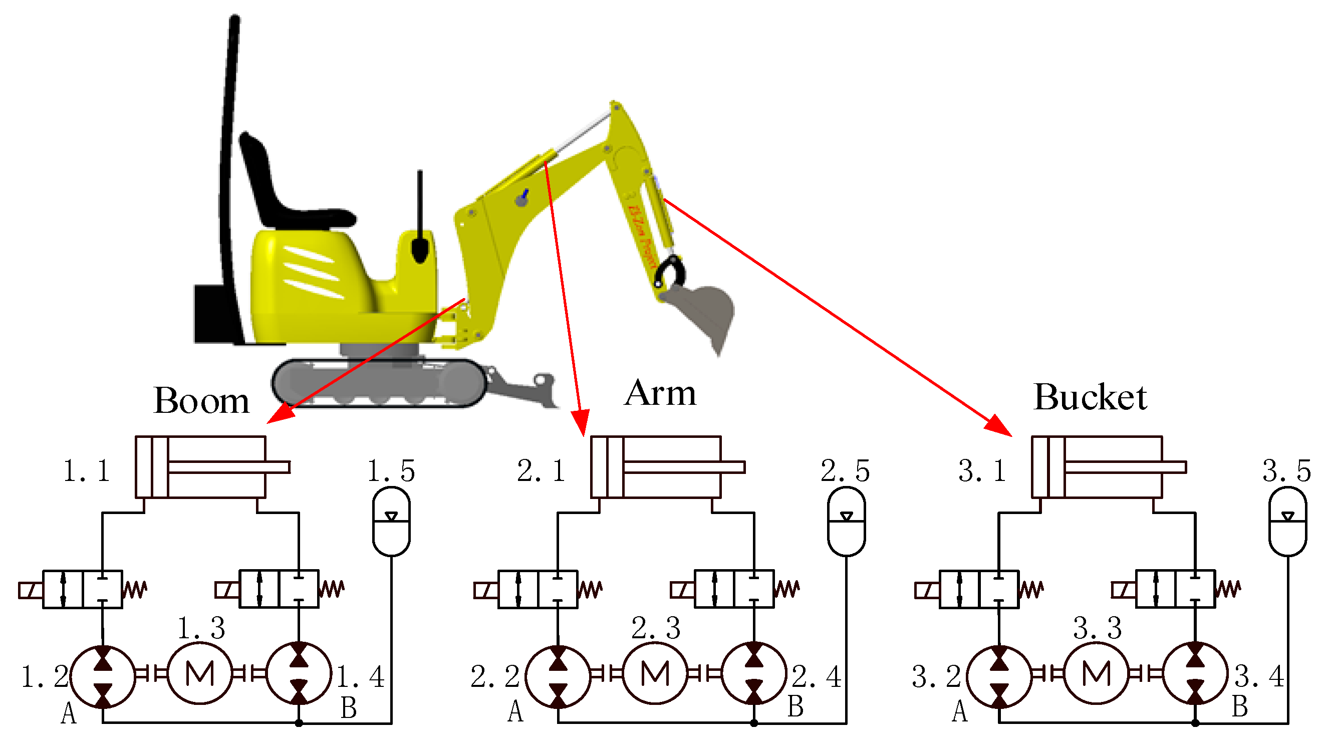
| Component | Figure 1 | Description and Dimensions | Mass (kg) |
|---|---|---|---|
| Boom cylinder | 1.1 | 60/30 × 325 mm | 16.0 |
| Pump/Motor | 1.2, 1.4 | External bi-directional gear motors by Hydac with displacements of 6.61 and 4.95 cm3/rev [18]. | 6.6 |
| Electric motor | 1.3 | MST130C-0200-F, 5.24 kW [19] | 6.6 |
| Hydraulic accumulator | 1.5 | 0.7L@1bar by Bosch Rexroth | 4.0 |
| Arm cylinder | 2.1 | 50/30 × 410 mm | 11.0 |
| Pump/Motor | 2.2, 2.4 | External bi-directional gear motors by Hydac with displacements of 6.67 and 4.27 cm3/rev [18]. | 2.4 |
| Electric motor | 2.3 | MST130C-0200-F, 5.24 kW [19] | 6.6 |
| Hydraulic accumulator | 2.5 | 0.7L@1bar by Bosch Rexroth | 4.0 |
| Bucket cylinder | 3.1 | 50/30 × 292 mm | 9.0 |
| Pump/Motor | 3.2, 3.4 | External bi-directional gear motors by Hydac with displacements of 6.67 and 4.27 cm3/rev [18]. | 2.4 |
| Electric motor | 3.3 | MST130C-0200-F, 5.24 kW [19] | 6.6 |
| Hydraulic accumulator | 3.5 | 0.7L@1bar by Bosch Rexroth | 4.0 |
| Component | Structure (kg) | Cylinder (kg) | DDH Units (kg) |
|---|---|---|---|
| Boom | 59.5 | 16.0 | 29.0 |
| Arm | 28.0 | 11.0 | 29.0 |
| Bucket (including linkage) | 40.0 | 9.0 | 29.0 |
| Material | Density (kg/m3) | Maximum Mass * (kg) | Weight (N) |
|---|---|---|---|
| Clay (Low plasticity index) | 1650 | 56.529 | 554.36 |
| Clay and gravel | 2100 | 71.946 | 705.549 |
| Sand | 2000 | 68.52 | 671.952 |
| Sand and gravel | 1950 | 66.807 | 655.153 |
| Sandstone (porous) | 2500 | 85.65 | 839.94 |
| Sandstone (cemented) | 2650 | 90.789 | 890.336 |
| Limestone | 2600 | 89.076 | 873.537 |
| Material Properties for Steel | Magnitude |
|---|---|
| Density | 7827.08 kg/m3 |
| Poisson’s ratio | 0.27 |
| Young’s Modulus | 199.948 GPa |
| Parameter | MGE102-630 | MGE102-450 | MGE101-630 | MGE101-400 |
|---|---|---|---|---|
| Displacement (cm3/rev) | 6.61 | 4.95 | 6.67 | 4.27 |
| Rotational speed (rpm) | 1450 | |||
| Oil kinematic viscosity at 40 °C (mm2/s) | 36 | |||
| Oil density at 40 °C (kg/m3) | 860 | |||
| Nominal pressure (bar) | 250 | 250 | 230 | 250 |
| Volumetric efficiency (%) | 93.1 | 91.5 | 95.4 | 94.0 |
| Hydromechanical efficiency (%) | 88.2 | 83.3 | 85.4 | 83.3 |
| No-load torque (Nm) | 0.05 | |||
| Cycle | Parameter | Weight of 3 DDH Units | |
|---|---|---|---|
| Without | With | ||
| Typical working cycle (payload 71.9 kg) | Energy consumption (kJ) | 8.1 | 9.4 |
| Overall efficiency (%) | 71.1 | 69.4 | |
| Regeneration energy (kJ) | 1.9 | 2.3 | |
| Regeneration efficiency (%) | 69.6 | 68.1 | |
| Modified digging Japanese cycle (payload 0 kg) | Energy consumption (kJ) | 4.9 | 5.8 |
| Overall efficiency (%) | 68.0 | 69.6 | |
| Regeneration energy (kJ) | 1.5 | 1.8 | |
| Regeneration efficiency (%) | 75.0 | 71.0 | |
| Modified levering Japanese cycle (payload 0 kg) | Energy consumption (kJ) | 3.5 | 3.9 |
| Overall efficiency (%) | 68.7 | 69.5 | |
| Regeneration energy (kJ) | 1.1 | 1.4 | |
| Regeneration efficiency (%) | 71.0 | 69.7 | |
© 2018 by the authors. Licensee MDPI, Basel, Switzerland. This article is an open access article distributed under the terms and conditions of the Creative Commons Attribution (CC BY) license (http://creativecommons.org/licenses/by/4.0/).
Share and Cite
Niraula, A.; Zhang, S.; Minav, T.; Pietola, M. Effect of Zonal Hydraulics on Energy Consumption and Boom Structure of a Micro-Excavator. Energies 2018, 11, 2088. https://doi.org/10.3390/en11082088
Niraula A, Zhang S, Minav T, Pietola M. Effect of Zonal Hydraulics on Energy Consumption and Boom Structure of a Micro-Excavator. Energies. 2018; 11(8):2088. https://doi.org/10.3390/en11082088
Chicago/Turabian StyleNiraula, Abinab, Shuzhong Zhang, Tatiana Minav, and Matti Pietola. 2018. "Effect of Zonal Hydraulics on Energy Consumption and Boom Structure of a Micro-Excavator" Energies 11, no. 8: 2088. https://doi.org/10.3390/en11082088
APA StyleNiraula, A., Zhang, S., Minav, T., & Pietola, M. (2018). Effect of Zonal Hydraulics on Energy Consumption and Boom Structure of a Micro-Excavator. Energies, 11(8), 2088. https://doi.org/10.3390/en11082088