1. Introduction
In recent years, DC distribution networks and AC/DC hybrid distribution networks are attracting increasing attention due to the increasing demand for distributed generation and the need for regional grid interconnection [
1,
2]. The AC/DC hybrid distribution network can satisfy the above requirements and achieve the interconnection and transition between the AC distribution network and the DC distribution network. Several AC distribution networks can be connected through DC lines, which can form a DC distribution network. Then, the entire AC and DC network can be called a regional multi-terminal AC/DC hybrid distribution network [
3]. Due to the low impedance of the DC distribution network, the fault currents will increase rapidly after a DC fault [
4]. More seriously, in the multi-terminal AC/DC hybrid distribution network, the fault currents of different converters are superimposed over each other, which results in the higher demands on the semiconductor devices in the system. If the fault cannot be detected as soon as possible and the faulty line is not isolated timely, the entire system will withstand significant losses. Therefore, it is necessary to carry out research on the fast detection method of DC faults in a multi-terminal AC/DC hybrid distribution network.
The research of the DC fault detection methods usually includes the primary detection methods and the backup detection methods. The primary detection methods mainly focus on the faults with low resistances, and the backup detection methods are mainly for the high-resistance faults. The fault currents of low-resistance faults are higher than that of high-resistance faults, which has a strict requirement for fault detection speed. It must be detected within 2 ms after the fault [
5]. Meanwhile the fault currents of high-impedance faults are lower, and the requirement for fault detection speed is relatively easier to meet. However, the backup detection method needs to detect all high-resistance faults accurately that are beyond the detection scope of the primary detection method.
References [
6,
7] use the current difference between the two ends of the DC line to identify the DC faulty line. This method requires the communication between both ends and is vulnerable to communication delay. The fault detection speed is low. Reference [
8] uses the first-order differential and second-order differential of the fault current to detect DC faults in a multi-terminal system, but this method is only useful for fault resistances below 10 Ω. As the fault resistance increases, the differential of the fault current will decrease, and false detection may occur. A voltage change rate-based fault detection method is proposed in [
9,
10], but it can only identify the faulty line and the fault type and fault poles are unknown. Reference [
11] uses the ratios of the high-frequency transient voltage amplitudes at the two ends of the CLI to detect DC faults. In addition, reference [
12] uses the ratios of the high-frequency transient voltage and current of the CLI to identify the fault type. However, the high-frequency transient signals can be affected by noise sometimes.
For the detection of high-resistance faults, a method based on the magnitude of the voltage change rate of the DC line is proposed in [
13]. While the fault type and fault poles cannot be identified by this method. In ref. [
14], a passive oscillation circuit is used to detect the DC high-resistance fault. The capacitors are connected to the CLIs in parallel to form the LC resonant circuits. The faults are identified by detecting the current components at a specific frequency after the faults. However, these components will decrease with the increase of the fault resistance. Therefore, it will be difficult to detect the fault when the fault resistance is high. When the detection of the DC fault is completed by the fault detection devices, the signal will be sent to the protection devices such as the DC circuit breakers and so on. Subsequently, the DC fault will be isolated quickly and successfully [
15,
16,
17,
18].
Research has also been carried out on the protection scheme of the DC grid [
19,
20,
21,
22,
23,
24,
25,
26]. A system protection scheme for the low-voltage DC microgrid is proposed in reference [
22]. However, this method mainly aims at the design of the protection scheme and the selection of the protection devices. Reference [
23] proposes an overcurrent-based DC distribution network protection scheme, which also focuses on the design of protection schemes. Based on the detailed analysis of the DC fault characteristics of the DC grid, reference [
24] summarizes the short-comings of the existing unit protection and non-unit protection methods. Then a flexible protection scheme design framework is proposed. Reference [
25] proposes a protection scheme focusing on the control for the short-circuit current and the fault ride-through scheme for the low-voltage distribution network. Reference [
26] focuses on the design of the electrical protection system of the multiterminal DC compact node. However, all the above studies focus on the protection scheme design for the DC faults. As the basis of the design of the protection scheme, the fault detection method is not investigated thoroughly.
In summary, research on DC fault detection methods for multi-terminal systems are still not comprehensive and in-depth. Therefore, it is urgent to design a fast detection method for DC faults that can identify the faulty line, determine the fault type and the fault poles quickly and accurately for multi-terminal AC/DC hybrid distribution networks.
Based on existing research, the voltage and current characteristics of CLIs after DC faults are analyzed in detail for a multi-terminal AC/DC hybrid distribution network in this paper. Then a DC fault detection method based on the voltage change rates of the CLIs is proposed. The method consists of two parts: a primary detection method and a backup detection method. The primary detection method uses the amplitude of the single-ended CLI voltage change rate to identify the faulty line, determine the fault type and the fault poles. The detection is fast and accurate. The backup detection method achieves the detection of the high-resistance faults by comparing the directions and amplitudes of the voltage change rates of the CLIs at both ends of the DC lines. Finally, the feasibility of the proposed method under different fault resistances, fault locations and current-limiting inductances is verified by simulations. In addition, the simulation results show that the proposed method is not affected by the power reversal of the converters, AC fault and communication delay.
2. Analysis of Fault Characteristics of CLI Voltage and Current
This section takes the multi-terminal radial AC-DC hybrid distribution network as an example to study. It is known from [
27] that after a DC pole-to-pole fault or a DC pole-to-ground fault, the insulated gate bipolar transistors (IGBTs) of the converters will be blocked immediately. In addition, both faults include the capacitor discharge stage and the AC current feeding stage. To prevent the anti-parallel diodes of the IGBTs from being damaged by the overcurrent at the end of the capacitor discharge stage, the DC circuit breakers need to isolate the faulty line before the end of this stage [
28]. Therefore, the fault detection must also be completed before the end of the capacitor discharge stage. Therefore, this paper mainly analyzes the fault characteristics of the CLI voltage and current during the capacitor discharge stage.
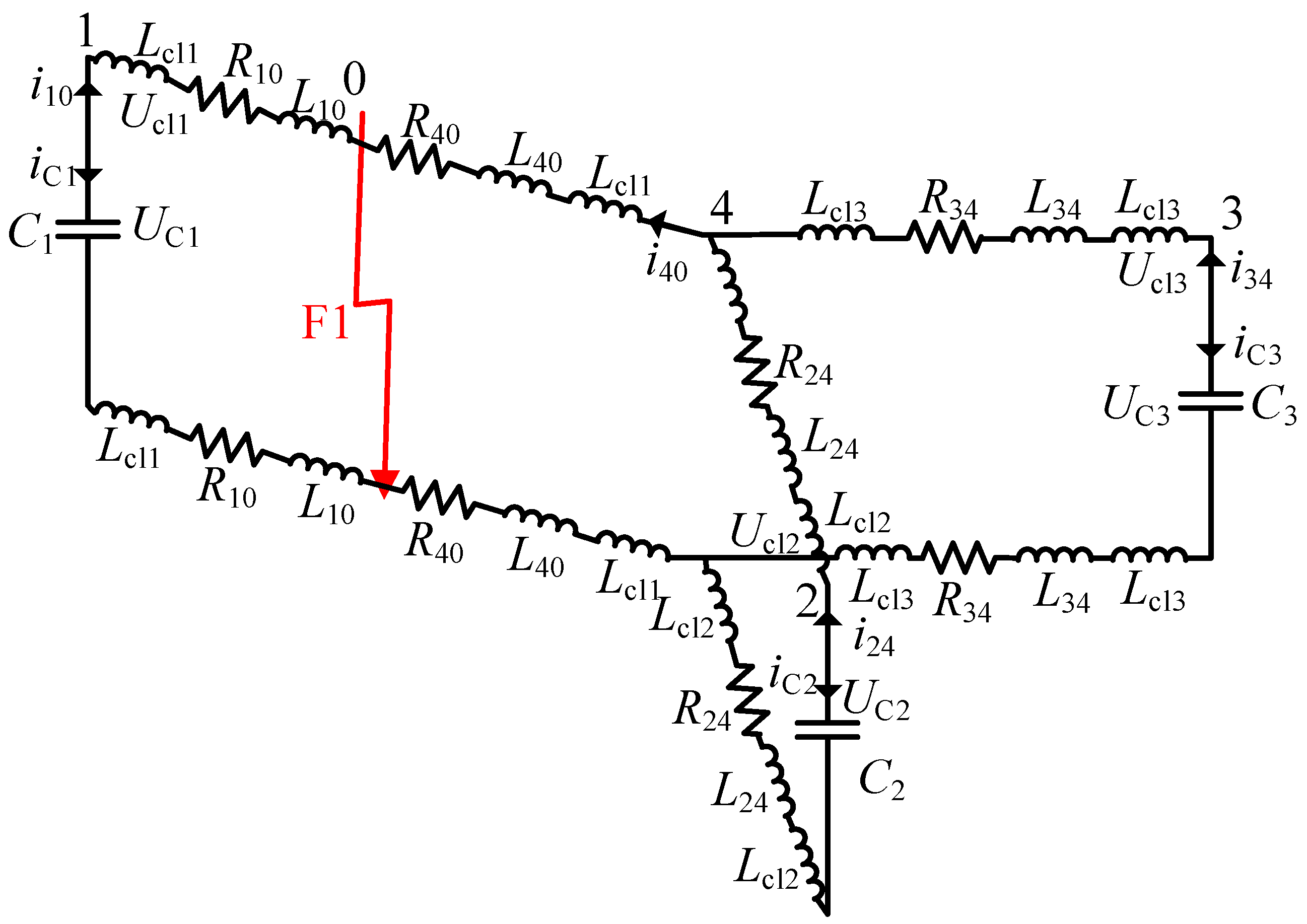
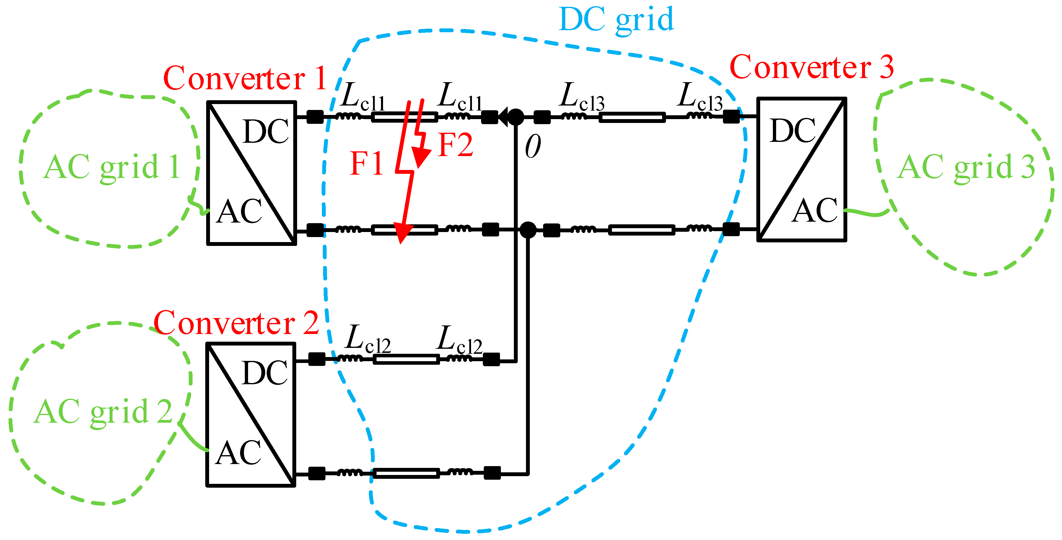
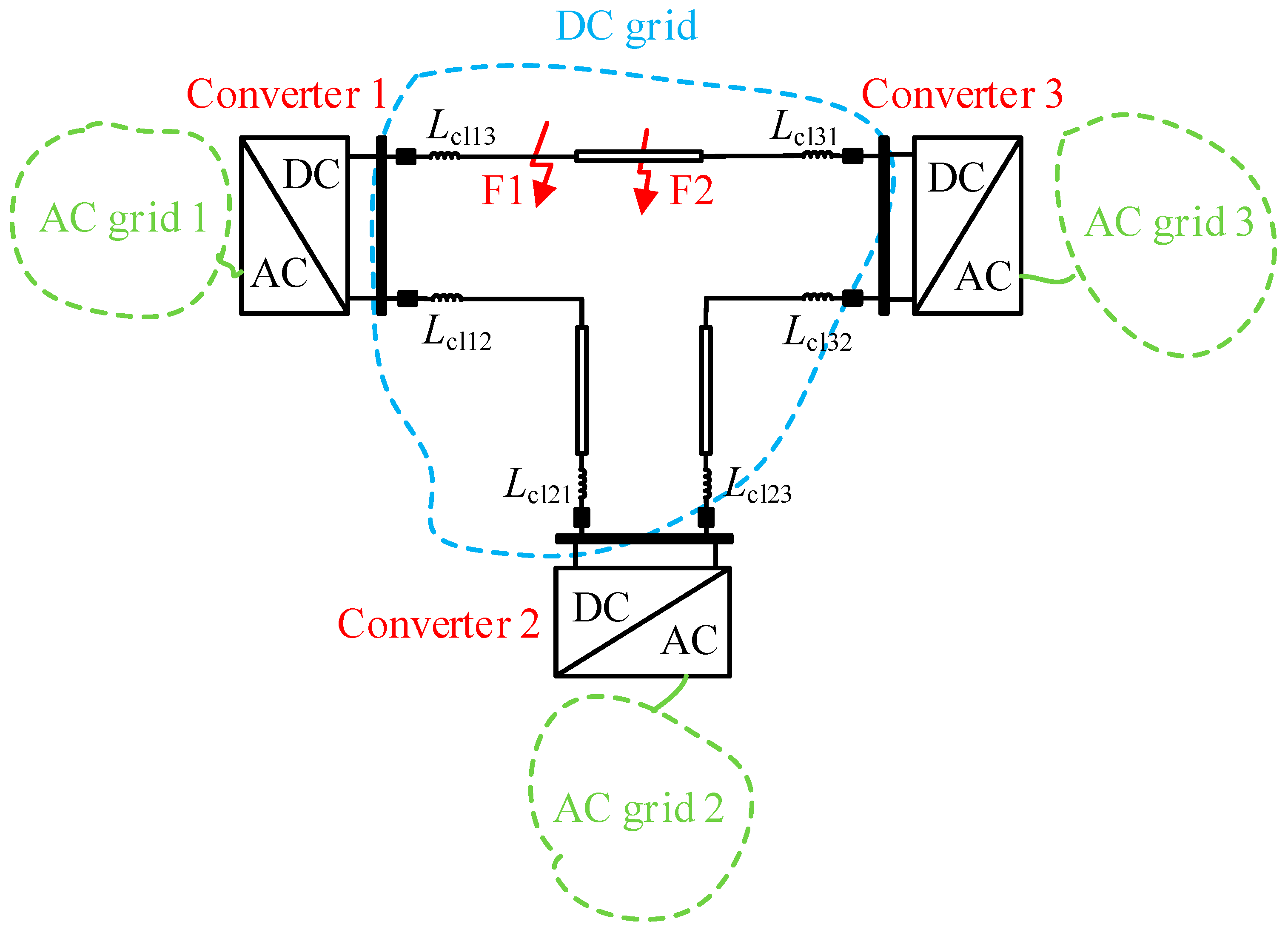
When the pole-to-pole fault F1 occurs on the DC line, the voltage source converters (VSCs) can be represented by their DC capacitors. The equivalent circuit of the three-terminal radial AC/DC hybrid distribution network during the capacitor discharge stage is shown in
Figure 1.
In
Figure 1,
,
and
are the equivalent DC capacitors of three converters.
,
and
are the inductances of the CLIs.
and
are the equivalent resistance and inductance of the DC line between the fault converter and the fault point.
and
are the equivalent resistance and inductance of the DC line between the fault point and the common point.
,
and
,
are the equivalent resistances and inductances of the DC lines of converter 2 and converter 3 respectively.
,
and
are the voltages of the CLIs.
,
and
are the voltages of the DC capacitors. When the pole-to-pole fault F1 occurs on DC line 14, the DC capacitors of all the converters start to discharge. The converters can be represented by their DC capacitors and the DC lines can be represented by the series of the line resistances and line inductors. Then the faulty line 14 is divided into two parts. One is from the converter 1 to the fault point and the other is from the fault point to the common point. Thus, during the DC capacitor discharge stage, the differential equations for the system can be obtained according to
Figure 1 as:
Then the currents of the CLIs on DC lines during the capacitor discharge stage can be obtained by solving (1) and (2). The voltage change rates of all CLIs can be expressed as:
As shown in (1), there is coupling between the differential equations of the non-faulty lines. It is difficult to get the analytical solutions of the voltage change rates of CLIs on the non-faulty lines. Equation (1) shows that the difference between the forms of the differential equations for the non-faulty lines and the faulty line is only shown by the third term on the right side. This is caused by the fault currents of non-faulty lines 24 and 34 and the equivalent resistance, inductance, and CLI of line 40, which leads to the coupling between the lines 24 and 34. However, the coupling only results in the difference of the magnitudes and directions of the voltage change rates of the CLIs between the faulty line and the non-faulty lines. The characteristics of the voltage change rates of the CLIs on the non-faulty lines are not affected by the coupling. Therefore, the equation of the faulty line is taken as an example here. The fault current of the faulty line can be expressed by solving (1) and (2) as:
where
is the initial value of the DC capacitor voltage.
is the initial value of the line current.
,
,
,
,
.
Substituting (4) into (3) yields:
When
, the voltage change rate of
is:
As shown in (4)–(6), the current of the CLI on the faulty line increases rapidly after the DC pole-to-pole fault. In addition, the CLI voltage rises at the same time from a value close to 0. Therefore, at the moment of the fault occurrence, the voltage change rate of the CLI on the faulty line will increase immediately. The CLI voltage and current will attenuate gradually afterwards, and the voltage change rate also decreases. For non-faulty lines, it can be seen from (1) that the CLI voltages and currents have similar characteristics except that the amplitudes and directions are different.
For the pole-to-ground fault, the impedance of the faulty line circuit during the capacitor discharge stage is only half of that of the pole-to-pole fault. Therefore, the voltage and current characteristics of the CLI are similar to the above analysis. After a pole-to-ground fault, the voltage change rate of the CLI on the faulty line can be expressed as:
where,
,
. When
, the voltage change rate of the CLI on the faulty line is:
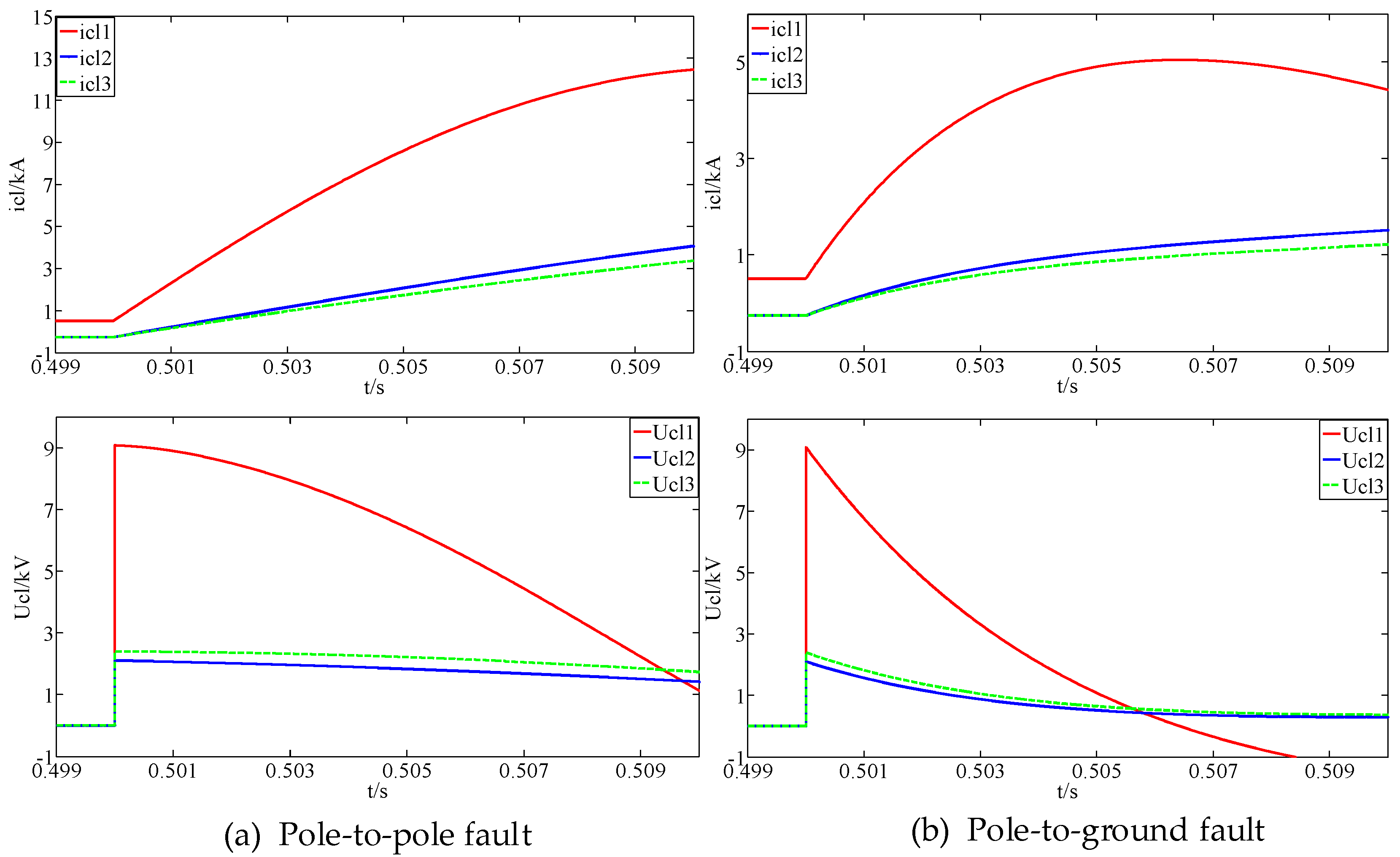
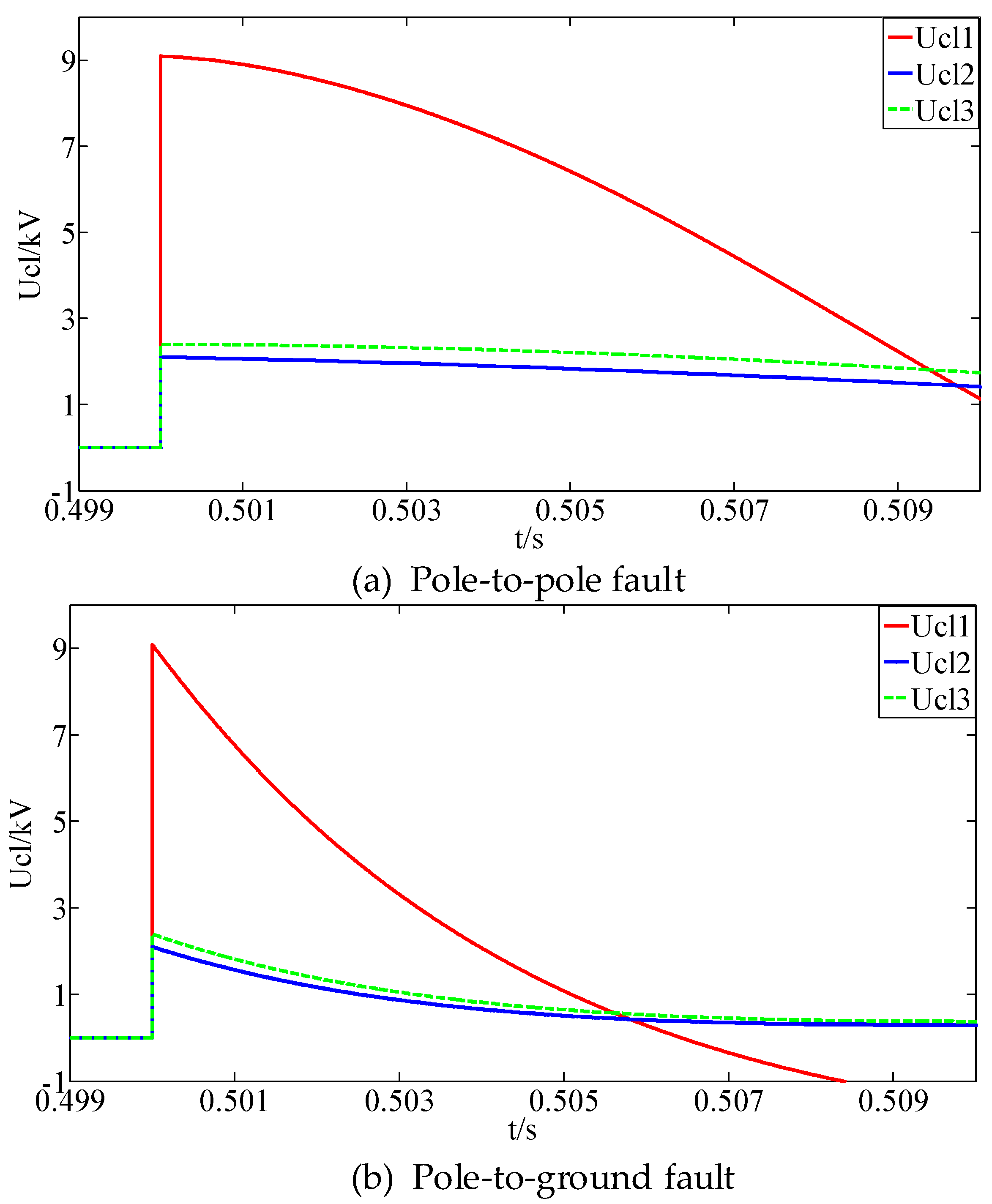
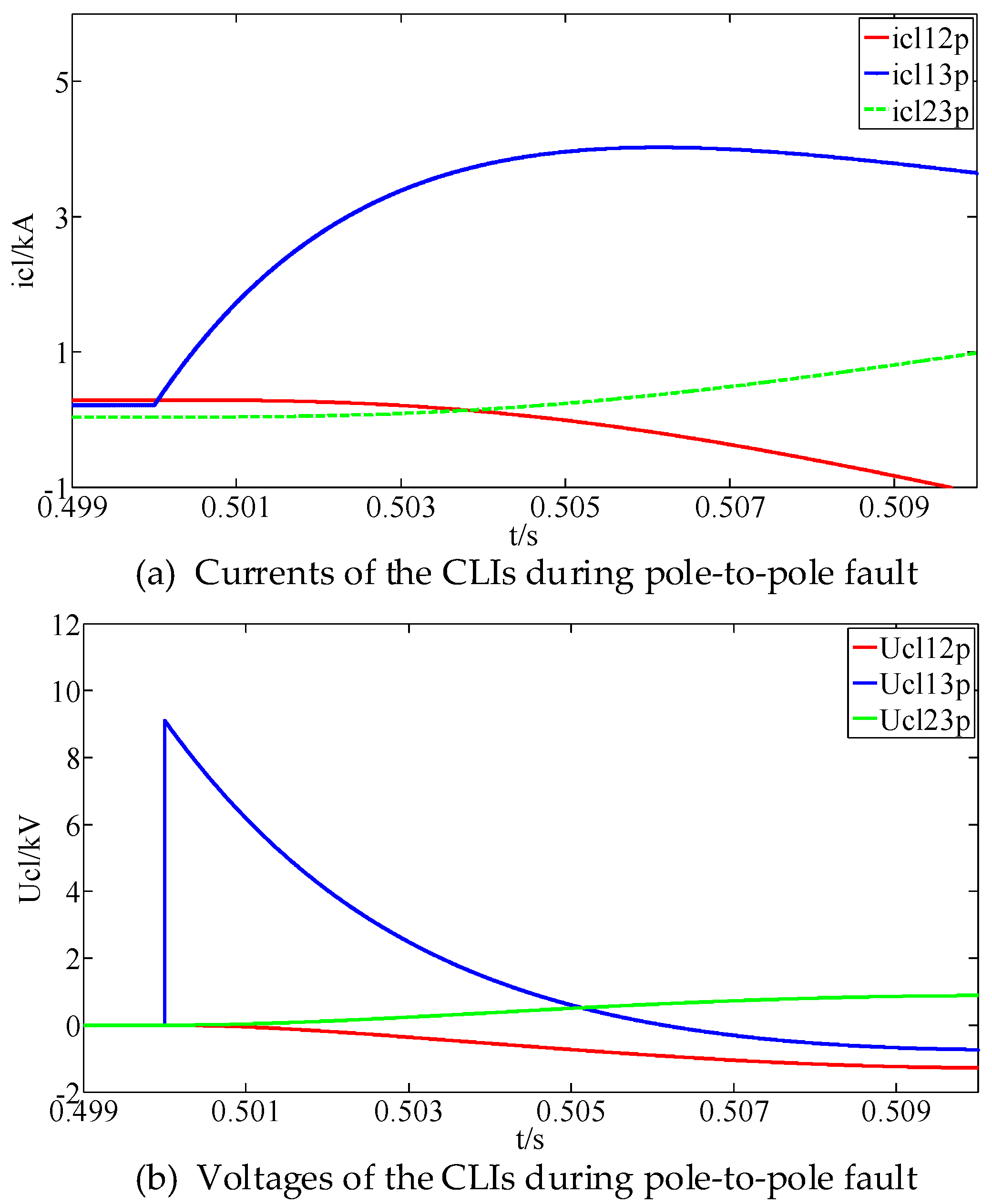
As shown in (7)–(9), after the pole-to-ground fault, the voltage change rate of the CLI on the faulty line reaches a maximum value quickly and then attenuates gradually, which is similar to that of the pole-to-pole fault. The simulation results of the currents and voltages of the CLIs during the pole-to-pole fault and pole-to-ground fault are shown in
Figure 2.
As shown in
Figure 2, after a DC fault, the rapid rise of the fault current causes the CLI voltages increasing to a peak value in a short time and then attenuating gradually with the decrease of the current change rates of the CLIs. The voltages of the CLIs are close to 0 during the normal operation. Therefore, the magnitudes of the CLI voltage change rates can be used to achieve fast and accurate detection of the DC faults. In addition, for the pole-to-pole fault and the pole-to-ground fault, the voltage change rate of the CLI on the faulty line is much higher than those on the non-faulty lines. Therefore, the faulty line identification, fault type determination and fault poles identification can be realized by comparing the voltage change rates of CLIs on different lines. Based on the above analysis, we can conclude that the voltage change rates of the CLIs can be used to detect the DC faults in a multi-terminal AC/DC hybrid distribution network.
3. Primary Fault Detection Method
This paper proposes a method for the fast detection of DC faults in a multi-terminal AC/DC hybrid distribution network based on the voltage change rates of the CLIs. The method includes a primary detection method and a backup detection method. The primary detection method is for usual low-resistance faults and the backup detection method is for high-resistance faults. This section gives a detailed introduction and analysis of the primary detection method.
The primary detection method includes three parts: faulty line identification, fault type determination, and fault poles identification.
3.1. Faulty Line Identification
From the analysis of the first section of this paper, we can see that after a DC fault, the faulty lines can be identified by detecting whether the voltage change rate of the CLI on each line is higher than the given threshold. The faulty line identification criterion is:
where,
is the number of the CLIs,
is the faulty line identification threshold, which can be selected by the calculation and simulation. When the voltage change rate of CLI on a certain line satisfies (10), it can be determined that this line is the faulty line.
3.2. Fault Type Determination
The fault type determination means the judgment of the pole-to-pole fault and the pole-to-ground fault. During a pole-to-pole fault, the positive-pole and negative-pole CLIs are both in the capacitor discharge circuit. Therefore, the voltage change rates of the positive-pole and negative-pole CLIs are almost equal. However, for the pole-to-ground fault, the voltage change rates of the positive-pole and negative-pole CLIs are completely different. This characteristic can be used as the determination criteria of the fault type:
where,
and
are the voltages of the positive-pole and negative-pole CLIs respectively.
is the fault type determination threshold. When the absolute value of the difference between the voltages of the positive-pole and negative-pole CLIs on the faulty line is lower than the fault type determination threshold, it can be concluded that the fault is a pole-to-pole fault. Otherwise, the fault is a pole-to-ground fault.
3.3. Fault Poles Identification
If in
Section 3.2, the fault is determined to be a pole-to-pole fault, there is no need to determine the fault poles. If it is determined that the fault is a pole-to-ground fault, a further identification of the fault pole is required. The proposed fault poles identification criteria are:
where,
is the fault poles identification threshold. When the difference between the voltage change rates of the positive-pole and negative-pole CLIs is higher than the threshold, the positive-pole is the fault pole. When this difference is negative and less than the threshold, a negative pole-to-ground fault is determined.
The value of the faulty line identification threshold, the fault type determination threshold and the fault poles identification threshold can be defined according to (4)–(9). The voltage change rates of all the CLIs can be obtained by solving (1)–(3). For the faulty line identification threshold, its value should be higher than the maximum value of the voltage change rates of the CLIs on the non-faulty lines and lower than the minimum value of the voltage change rate of the CLI on the faulty line. The higher the faulty line identification threshold is, the more accurate the faulty line identification will be and the longer the time for the identification will be. Therefore, the exact value of the faulty line identification threshold should be defined according to the requirement of the fault detection. For the fault type determination threshold and the fault poles identification threshold, their values can be set to 0 theoretically. However, to provide enough margin, their values should be a little higher than 0. In addition, the maximum values of them are mainly limited by the fault detection time.
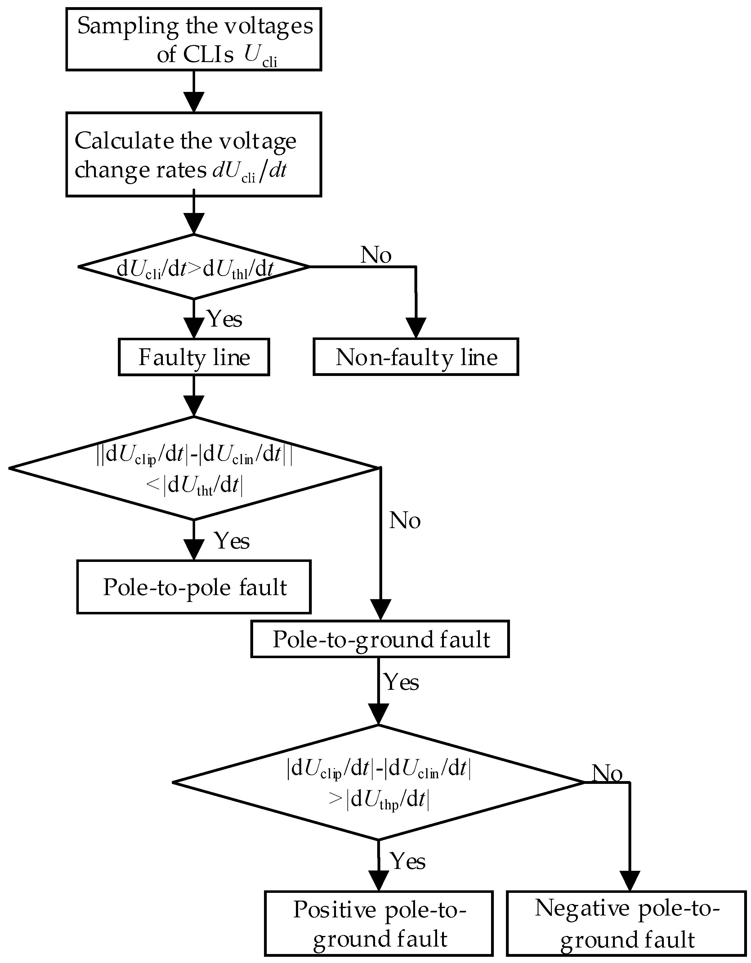
The flow chart of the primary fault detection method for DC faults is shown in
Figure 3.
As shown in
Figure 3, the first step of the primary fault detection method proposed in this paper is to acquire the voltage signals of the CLIs and calculate the voltage change rates of them. Then according to the criteria of the faulty line identification, fault type discrimination and fault poles identification, the fault poles can be determined. Finally, the trigger signal is sent to the protection devices of the fault poles.
The proposed method uses only the data of the single-ended CLI to achieve the faulty line identification, fault type determination and fault poles identification. The communication between the two ends of DC lines is unnecessary. Therefore, it is fast and accurate enough for the detection of DC faults.
4. Backup Fault Detection Method
When a high-resistance fault occurs, the voltage change rates of the CLIs are much lower than that of the usual DC faults. The primary fault detection method may fail, and the fault cannot be detected correctly. Therefore, this section proposes a backup fault detection method for the high-resistance faults.
The backup fault detection method includes two parts: faulty line identification and fault type determination. Let the bus-to-line direction be the positive direction. For the faulty line, the directions of the voltage change rates of the CLIs at the two ends are always opposite to each other. While the voltage change rates of the CLIs at the two ends of the non-faulty lines are in the same directions. Therefore, this characteristic can be used to identify the faulty line. The faulty line identification criteria are:
where,
and
are the voltage change rates of the CLIs on two ends of the DC lines respectively. The faulty line of the high-resistance fault can be identified according to (13). This method is not affected by the fault resistance and is suitable for the high-resistance fault.
According to the analysis of the second section of this paper, after a pole-to-pole fault, the voltage change rates of the positive pole and negative pole CLIs are almost the same. While for the pole-to-ground fault, the voltage change rates of the positive-pole and negative-pole CLIs are completely different. Therefore, the fault type can be determined based on the following criteria:
where,
is the fault type identification threshold. When the voltage change rates of the CLIs at the two ends of the faulty line satisfies (14), the fault type of the high-resistance fault can be determined. The value of the faulty fault type identification threshold can be set to 0 theoretically. However, to provide enough margin and selectivity, its value can be higher than 0. In addition, the maximum value is mainly determined by the requirement of the fault detection time.
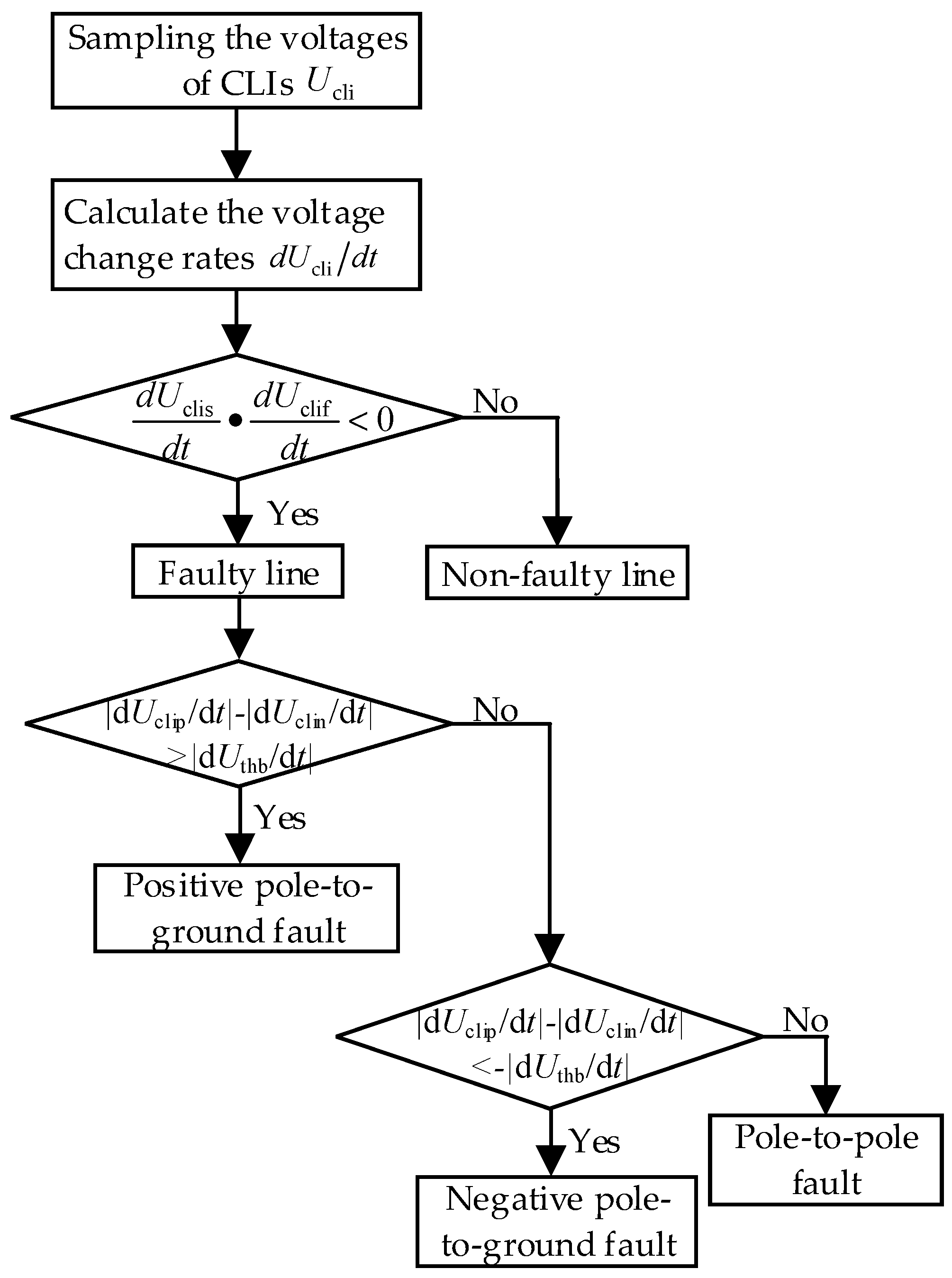
The flow chart of the proposed backup fault detection method is shown in
Figure 4.
As shown in
Figure 4, the voltage change rates of the CLIs at both ends of the DC lines are compared in the backup fault detection method. Therefore, the detection time is longer than that of the primary detection method. However, the fault current of the high-resistance fault is much smaller than that of the usual fault, which leads to a lower requirement for the detection time. In addition, the proposed method only needs to send the fault detection signals at one end to the other, so the fault detection result is not affected by the communication delay.
5. Simulation
Figure 5 shows the simulation model of the three-terminal radial AC-DC hybrid distribution network built in MATLAB. Converter 1 uses the constant DC voltage control. Converters 2 and 3 use the constant active power control. The parameters of the simulation model are shown in
Table 1.
The simulation model consists of three AC distribution networks which are connected by DC distribution network. The DC circuit breakers and CLIs are configured at both ends of each DC line.
5.1. Primary Detection Method Verification
The pole-to-pole fault and pole-to-ground fault are applied at 0.5 s at the fault positions F1 and F2 respectively. In addition, the voltages of the CLIs during the faults are shown in
Figure 6.
As shown in
Figure 6, after the DC faults F1 and F2, the currents flowing through the CLIs on all DC lines increase rapidly, which cause the voltages to increase immediately from 0 during normal operations. Then the voltages of the CLIs attenuate gradually, which is consistent with the above analysis. There is an evident difference in the voltage change rates of the CLIs on the faulty and non-faulty lines.
The pole-to-pole fault and pole-to-ground fault are detected using the proposed primary detection method. According to the system parameters, the faulty line identification threshold, fault type determination threshold and fault poles identification threshold are set at
,
and
respectively. The fault detection results of the pole-to-pole and pole-to-ground faults are shown in
Table 2.
Table 2 shows that after the pole-to-pole and pole-to-ground faults, the voltage change rates of the CLIs on the faulty lines are higher than the faulty line identification threshold
. In addition, the voltage change rates of the CLIs on the non-faulty lines are less than
. The faulty lines can be identified correctly. For the pole-to-pole fault, the difference between voltage change rates of the positive pole and negative pole CLIs on the faulty line is 0, which is lower than the fault type determination threshold
. Therefore, the pole-to-pole fault can be determined accurately. For the pole-to-ground fault, the fault type determination difference is higher than
, so the fault type can be correctly identified. This difference satisfies the fault poles identification criteria at the same time. Therefore, it is determined to be a positive pole-to-ground fault.
Above all, the proposed primary fault detection method can achieve fast and accurate detection of the DC faults in the multi-terminal radial AC/DC hybrid distribution network.
5.2. Backup Detection Method Verification
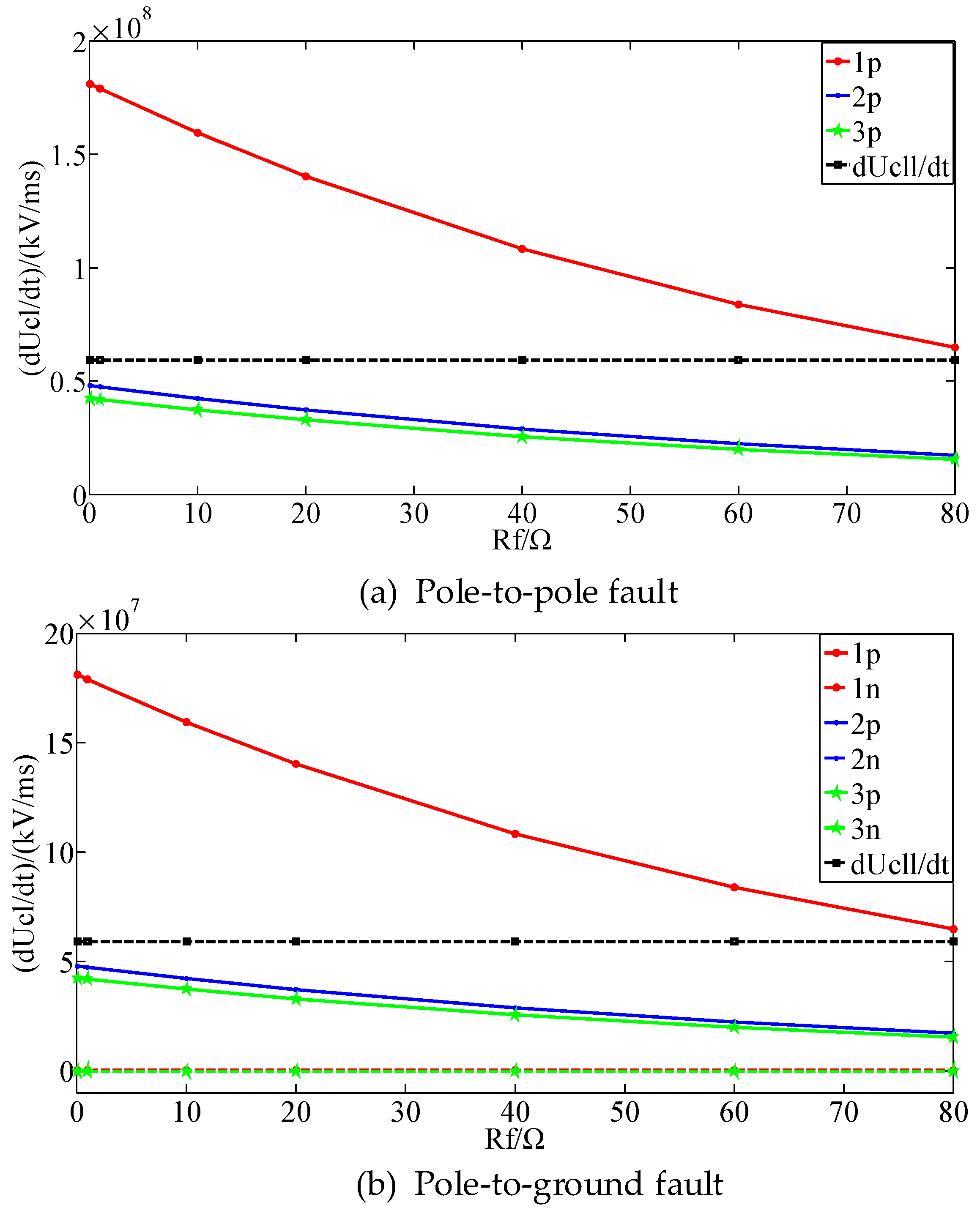
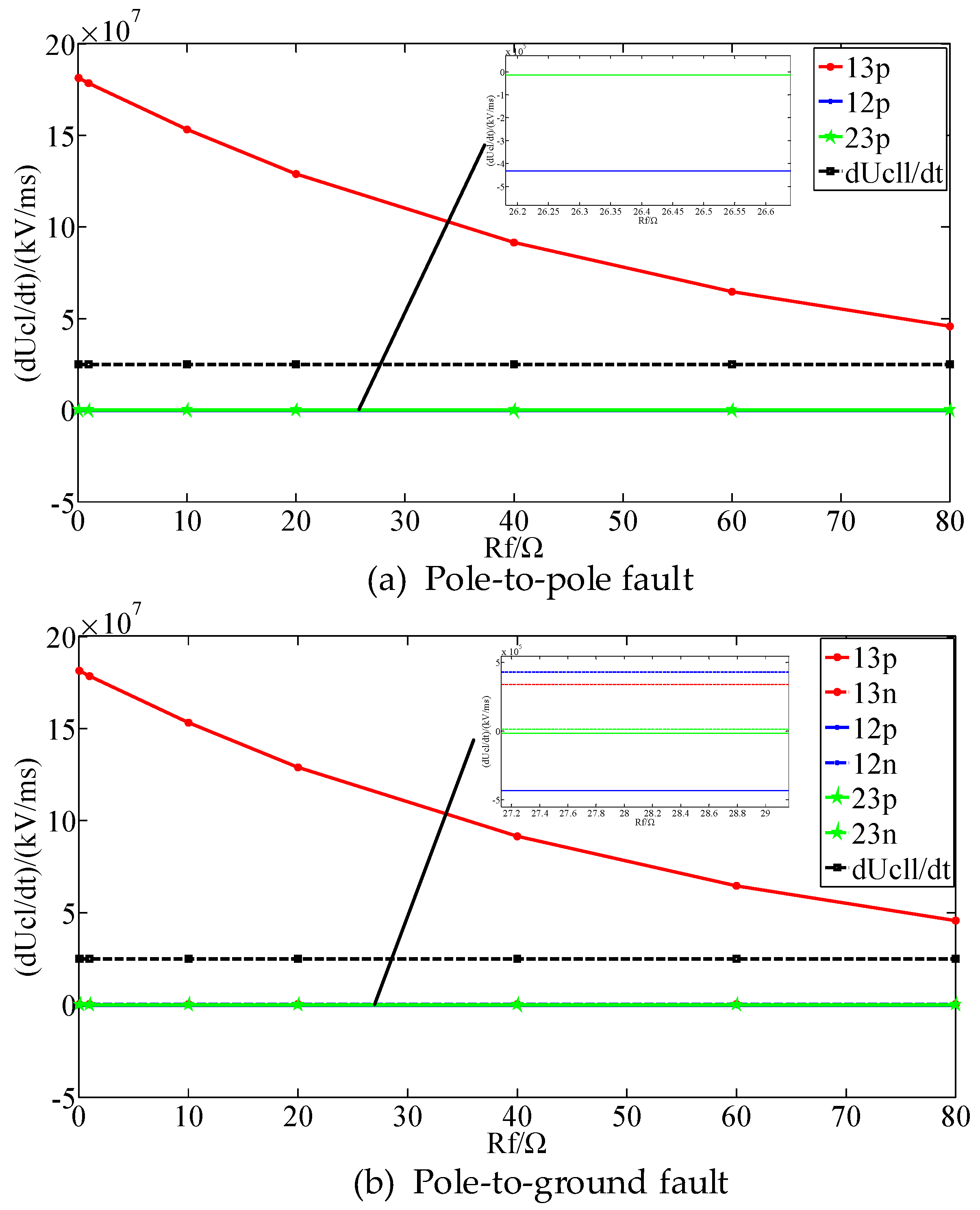
The pole-to-pole fault and pole-to-ground fault are applied at 0.5 s at the fault positions F1 and F2 respectively. In addition, the fault resistance varies from 0 Ω to 80 Ω. The voltage change rates of the CLIs are shown in
Figure 7.
As shown in
Figure 7, as the fault resistance increases, the voltage change rates of the CLIs decrease. This is because the increase in the fault resistance leads to the increase of the impedances of the capacitor discharge circuits, which results in a reduction in the rise rates of the fault currents and a decrease in the voltage change rates of the CLIs. When the fault resistance is less than 80 Ω, the voltage change rates of the CLIs on the faulty line and the non-faulty lines are always higher than the faulty line identification threshold
, so the primary fault detection method can achieve fault detection correctly. The fault detection results when the fault resistance varies are shown in
Table 3.
As shown in
Table 3, when the fault resistance varies, the proposed fault detection method can achieve the faulty line identification, fault type determination, and fault poles identification accurately.
However, obviously, when the fault resistance continues to increase, the voltage change rates of the CLIs will keep decreasing and the voltage change rate of the CLI on faulty line may be lower than the faulty line identification threshold. The primary fault detection method will become ineffective. At the same time, the fault type determination and fault poles identification criteria will also fail. Therefore, when a high-resistance fault occurs in the system, a backup fault detection method needs to be started.
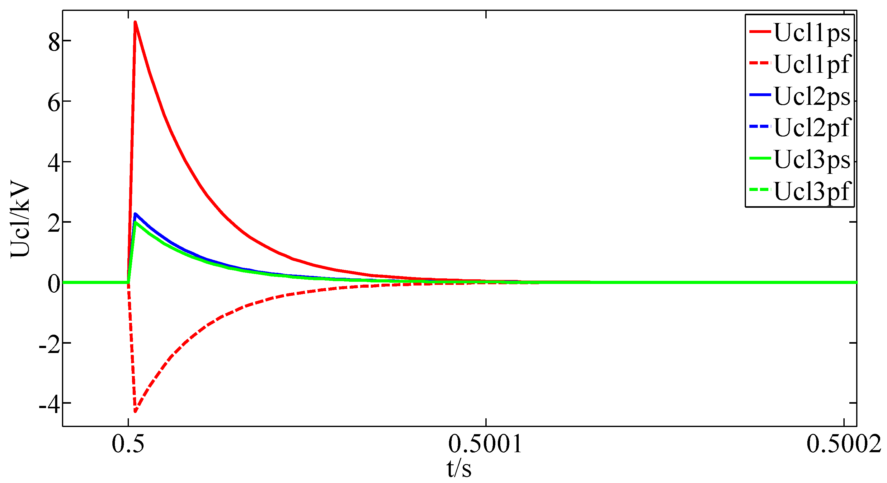
With a fault resistance of 200 Ω, a pole-to-pole fault is applied at the system. The voltages of the CLIs are shown in
Figure 8.
and
are the voltages of the CLI at the near end and far end of each DC line respectively.
As shown in
Figure 8, when the fault resistance is 200 Ω, the directions of the voltage change rates of the CLI at the two ends of the faulty line is different. While for the non-faulty lines, the directions of voltage change rates of the CLIs at two ends are the same. Therefore, the criteria of the backup fault detection method are satisfied, and the faulty line can be identified. When a pole-to-ground fault occurs, the characteristics of the voltage change rates of the CLIs also satisfy the above criteria. The simulation results of the voltage change rates of the positive-pole and negative-pole CLIs at the two ends of the faulty line after the pole-to-pole and pole-to-ground faults are shown in
Table 4.
As shown in
Table 4, after the pole-to-pole and pole-to-ground faults, the directions of the voltage change rates of the CLIs at the two ends of the faulty line are different and for the non-faulty line, the two directions are the same, which has been analyzed above. According to the simulation results, the fault type determination threshold is set at
. For the pole-to-pole fault, the difference between the voltage change rates of the two poles of the faulty line is close to 0, which is lower than the fault type determination threshold
. According to (14), the fault can be identified as a pole-to-pole fault. For the pole-to-ground fault, the difference between the voltage change rates of the two poles of the faulty line is
, which is higher than
. According to the first equation of (14), the fault can be identified as a pole-to-ground fault.
Above all, the proposed backup fault detection method can achieve accurate detection of the high-resistance faults and make up the weaknesses of the primary detection method. Although the backup detection method requires the communication between both ends of the lines, only the directions and amplitudes of the voltage change rates of the CLIs are sent and the time synchronization is not required at both ends. Therefore, the detection results are not affected by the communication delay, which ensures a great performance.
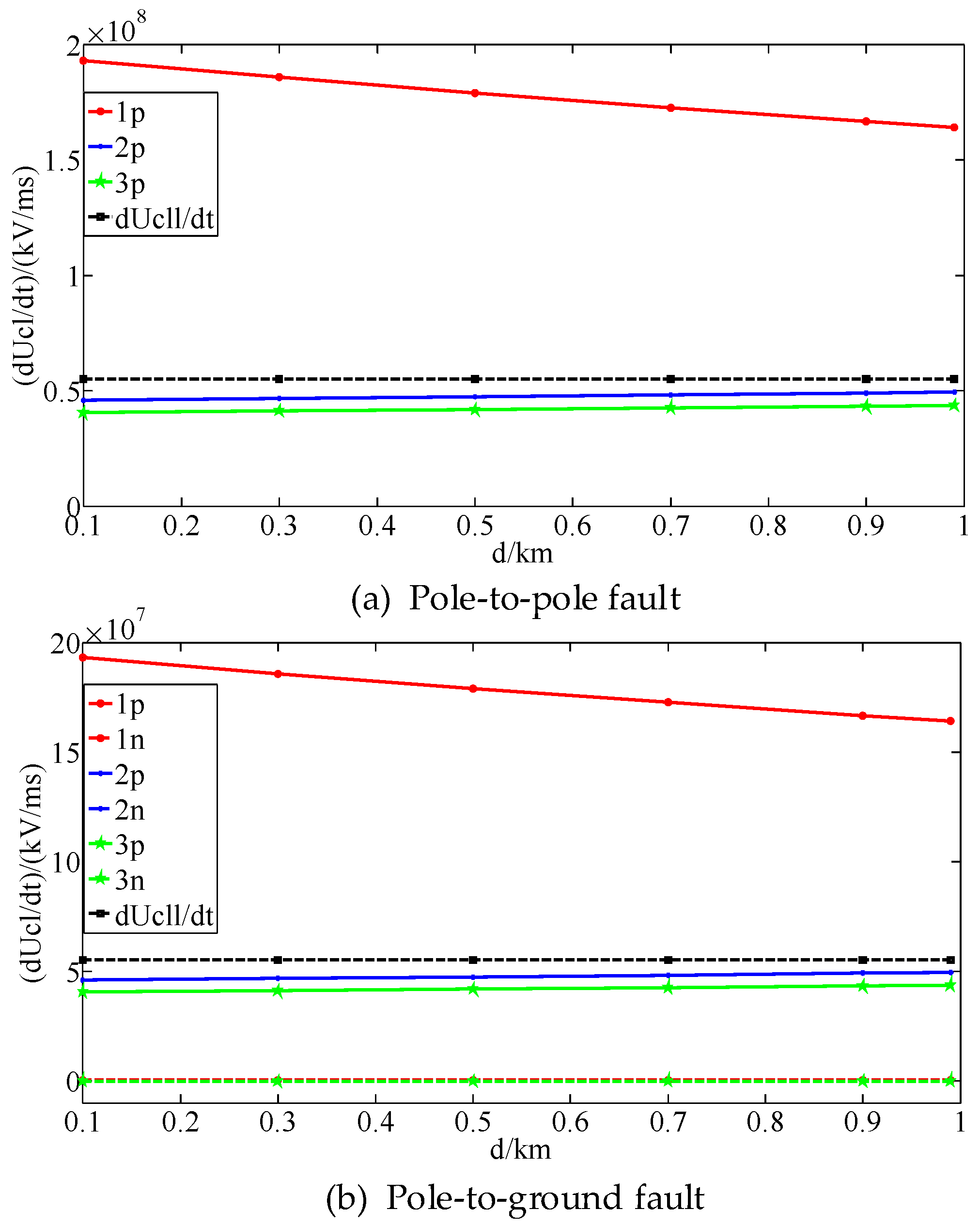
5.3. Influence of Fault Location on Proposed Method
The pole-to-pole fault and pole-to-ground fault are applied at the system respectively. In addition, the fault distance varies from 0.1 km to 0.99 km. The voltage change rates of the CLIs during the faults are shown in
Figure 9.
Figure 9 shows that as the fault distance increases, the impedance of the capacitor discharge circuit of each converter increases. Therefore, the fault current of each line decreases and the voltage change rates of the CLIs decrease. However, because the DC lines of the AC/DC hybrid distribution network are relatively short, and the line resistances and inductances are both low, the influence of the change in fault location on the voltage change rates of the CLIs is slight. When the fault distance increases gradually, the voltage change rate of the CLI on the faulty line decreases at the same time, and for the non-faulty lines, the rates remain almost constant. The fault detection results when the fault distance varies are shown in
Table 5.
As shown in
Table 5, when the fault location varies, the proposed fault detection method can achieve the faulty line identification, fault type determination, and fault poles identification accurately. The fault detection method has high speed and enough accuracy.
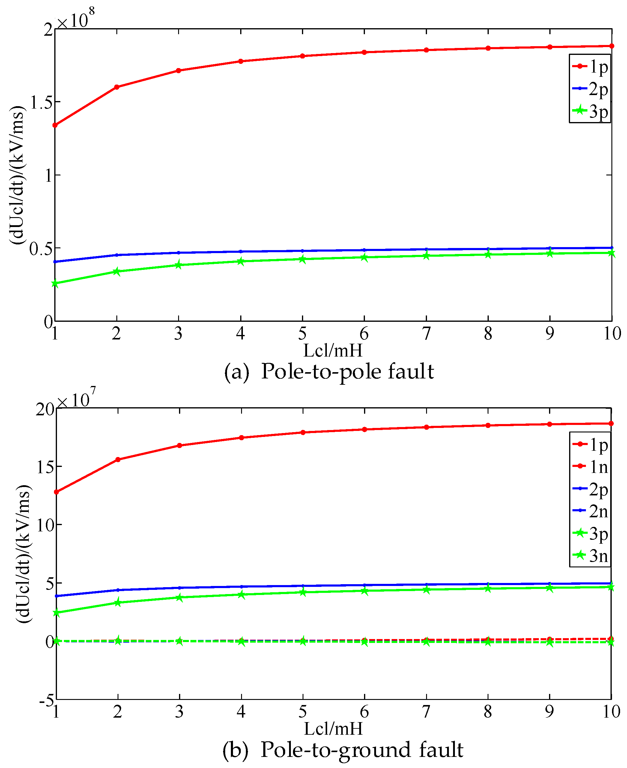
5.4. Influence of Current-Limiting Inductance on Proposed Method
The pole-to-pole fault and pole-to-ground fault are applied at the system respectively. In addition, the current-limiting inductance varies from 1 mH to 10 mH. The voltage change rates of the CLIs during the faults are shown in
Figure 10.
As shown in
Figure 10, for the pole-to-pole and pole-to-ground faults, with the increase of the current-limiting inductances, the voltage change rates of the CLIs on the faulty line and non-faulty lines increase greatly at first and then rise slowly. The voltage change rates of the CLIs on the faulty line is always higher than the faulty line identification threshold. For non-faulty lines, the values are lower than the threshold. The difference of the voltage change rates between the positive-pole and negative-pole CLIs is relatively constant. The proposed faulty line identification, fault type determination, and fault poles identification criteria are always valid. Therefore, the proposed fault detection method can achieve fast and accurate detection of DC faults under different current-limiting inductances.
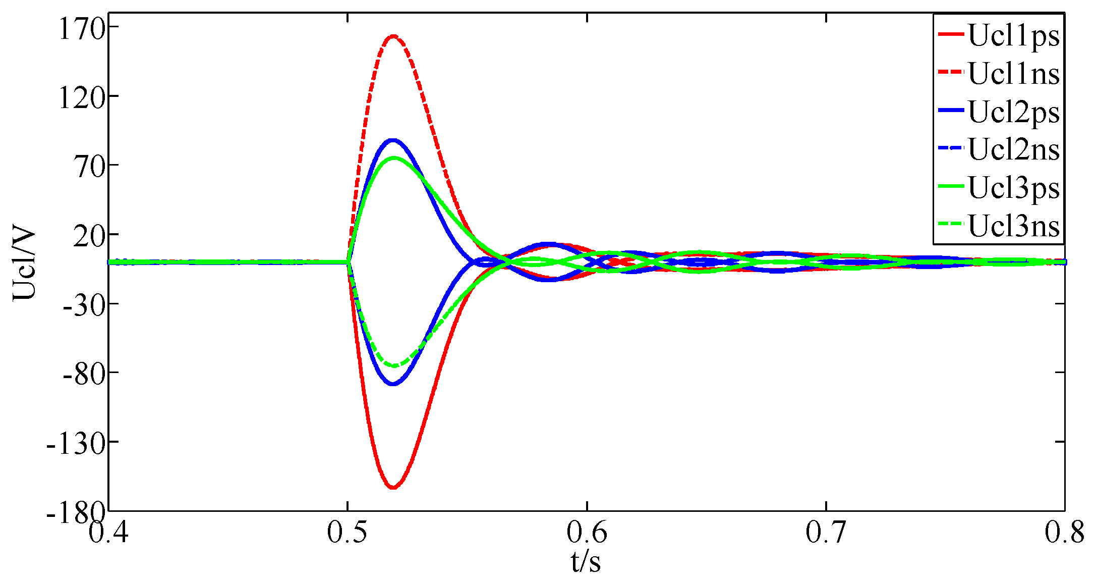
5.5. Influence of Power Reversal on Proposed Method
The active power of the converters 2 and 3 are set to reverse from 2.5 MW to −2.5 MW at 0.5 s, and the voltage waveforms of the CLIs are shown in
Figure 11.
As shown in
Figure 11, when the power of the converters 2 and 3 reverse at 0.5 s, the voltages of the CLIs increase rapidly, but the voltage change rates are less than that of the pole-to-pole and pole-to-ground faults. The maximum voltage of the CLIs is only 170 V, which is far below the faulty line identification threshold. Therefore, the power reversal does not affect the proposed fault detection method.
5.6. Influence of AC Fault on Proposed Method
A three-phase fault is applied on the AC side of the converter 1 at 0.5 s. The voltage waveforms of the CLIs are shown in
Figure 12.
As shown in
Figure 12, after a three-phase AC fault, the voltages of the CLIs increase rapidly and then attenuate gradually. The maximum amplitude of the voltage of the CLIs is less than 400 V, and the voltage change rates of the CLIs are much lower than that of the DC fault. Therefore, the AC fault does not affect the DC fault detection method proposed in this paper.
5.7. Influence of DC Line Voltage Disturbance on Proposed Method
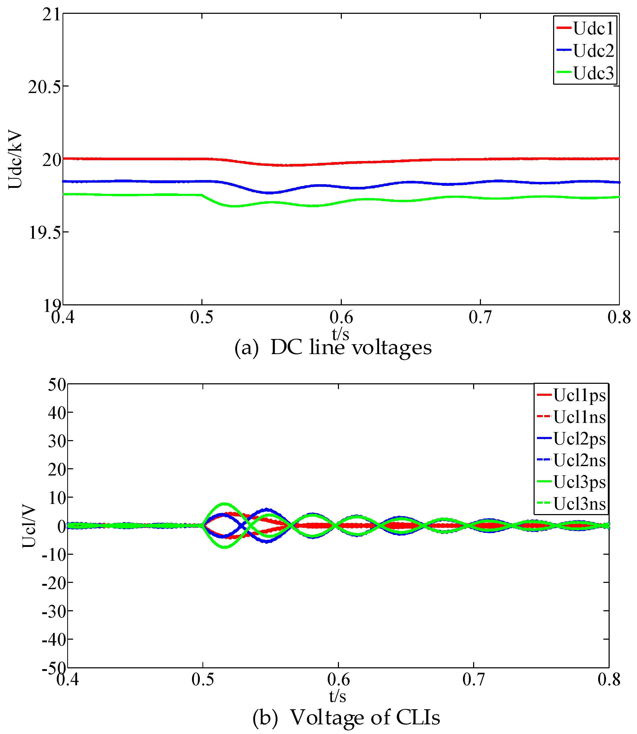
A DC line voltage disturbance is applied on the DC line of converter 3 at 0.5 s. The voltages of the DC lines and the CLIs are shown in
Figure 13.
As shown in
Figure 13, after a DC line voltage disturbance, the voltages of the DC lines changes and the voltages of the CLIs start to oscillate. However, the disturbance is small and the oscillation amplitudes of the voltages of the CLIs are less than 10 V, which has no influence on the results of the DC fault detection. Therefore, the proposed method keeps unaffected by the DC line voltage disturbance. Furthermore, the time of the DC fault ride-through is much longer than that of the fault detection [
29,
30]. Therefore, the influence of the voltage regulation and control on the fault detection method can be ignored and is not considered in this paper.
5.8. Fault Detection of Multi-Terminal Ring AC/DC Hybrid Distribution Network
Take the ring AC/DC hybrid distribution network as an example to verify the proposed method. The topology of the three-terminal ring AC-DC hybrid distribution network is shown in
Figure 14. The model parameters in
Figure 14 are the same as the model shown in
Figure 5 except the connection way of the converters.
5.8.1. Influence of Fault Resistance on Proposed Method
The pole-to-pole fault is applied at 0.5 s at the fault position F1. The currents and voltages of the CLIs after the fault are shown in
Figure 15.
As shown in
Figure 15, after the pole-to-pole fault on the DC line 13, the currents and voltages of the CLIs increase rapidly and then attenuate gradually, which is similar to the case in the radial network. There is an evident difference in the voltage change rates between the CLIs on the faulty line and non-faulty lines. Therefore, the proposed fault detection method can be used in this system.
The pole-to-pole fault and pole-to-ground fault are applied at 0.5 s at fault positions F1 and F2. In addition, the fault resistance varies from 0 Ω to 80 Ω. The voltage change rates of the CLIs are shown in
Figure 16.
As shown in
Figure 16, for the pole-to-pole fault, the voltage change rates of the CLIs on the faulty line decrease as the increase of the fault resistance, and the voltage change rates of the CLIs on the non-faulty lines keep almost unchanged. The voltage change rates of the CLIs on the faulty lines are always greater than that of the non-faulty lines and the proposed fault detection method is always feasible. For the pole-to-ground fault, the influence of the fault resistance on the voltage change rates of the CLIs is similar to that of the pole-to-pole fault. The proposed fault detection method can detect the pole-go-ground fault accurately. Therefore, in the ring AC-DC hybrid distribution network, the proposed fault detection method is also feasible and is not affected by the fault resistance.
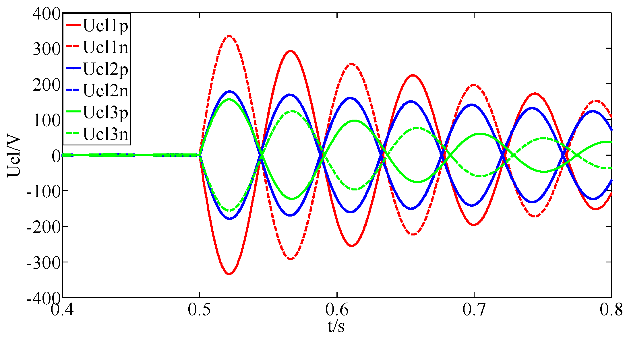
5.8.2. Influence of Power Reversal on Proposed Method
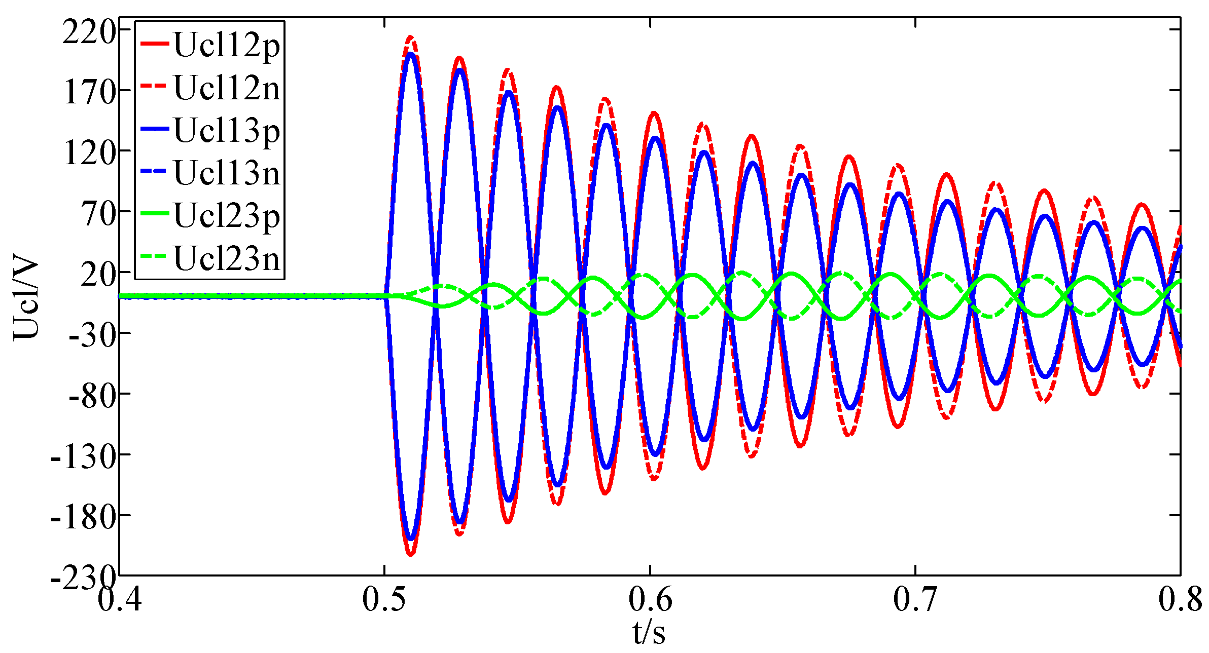
The active power of the converters 2 and 3 are set to reverse from 2.5 MW to −2.5 MW at 0.5 s, the voltage waveforms of the CLIs are shown in
Figure 17.
As shown in
Figure 17, when the power of the converter stations 2 and 3 reverse at 0.5 s, the voltages of the CLIs will increase, but the maximum value of them is about 220 V, which is much lower than that of the DC faults. Therefore, the power reversal does not affect the proposed fault detection method in the ring AC/DC hybrid distribution network.
In conclusion, the proposed fault detection method can achieve DC fault detection of multi-terminal AC/DC hybrid distribution network under various fault conditions, including different fault resistances, different fault locations, different current-limiting inductances and power reversal of converters. The primary fault detection method and backup fault detection method can detect all DC faults with different resistances and will not be triggered falsely by the AC faults.
6. Conclusions
This paper analyzes the voltage and current characteristics of the CLIs in the AC/DC hybrid distribution network and concludes that the voltages of the CLIs increase rapidly after the DC line faults and then attenuate gradually. The proposed fault detection method based on the voltage change rate of the CLI can detect low-resistance and high-resistance faults quickly and accurately. For the low-resistance fault, the voltage change rates of the single-ended CLIs are used to detect the faulty line, fault type and fault poles. For the high-resistance fault, the voltage change rates of the CLIs on two ends of the DC lines are used to identify the faulty line. Then the voltage change rate of the CLI on one end of the faulty line is used to determine the fault type and fault poles. The fault detection criteria are simple and easy to be achieved. In addition, the DC faults can be detected within 2 ms. The simulation results show that the proposed method is not affected by the fault location and the DC pole-to-pole fault and pole-to-ground fault can be detected accurately under different fault locations. The inductances of the CLIs, the power reversal and the DC line voltage disturbance have little influence on the voltage change rates of the CLIs and the proposed method is feasible under these conditions. The AC fault can lead to the oscillation of the voltage change rates of the CLIs, while the influence is too little to affect the fault detection results. When the fault resistance varies, the primary detection method and the back-up detection method can work together and detect all kinds of DC faults quickly and accurately. In addition, the proposed method is also suitable for multi-terminal AC/DC hybrid distribution networks with different topologies such as radial topology, ring topology and so on.
In summary, the proposed DC fault detection method for the AC/DC hybrid distribution network bases on the voltage change rates of the CLIs, which is easy to sample and calculate. The detection of the DC faults can be completed within 2 ms. In addition, the fault characteristics used by the proposed method is accurate enough to determine the faulty line, fault type and fault poles. The primary detection method satisfies the requirement of the detection time and the back-up detection method uses the signals from two ends of the faulty line, which needs more detection time than the primary detection method but is not affected by the change of fault resistances. All kinds of DC faults can be detected accurately using the proposed method and the accuracy is up to 100%. This leads to the fast and accurate operation of the protection devices and is beneficial to the isolation of DC faults. Furthermore, the proposed method is feasible to any DC faults that have a DC capacitor discharge stage. The proposed method has high reliability, low cost and high robustness, which indicates a promising application in the multi-terminal AC/DC hybrid distribution network. In future, the proposed method will be applied in the model built by the RT-LAB and its feasibility will be verified further in subsequent publications.


