Article

Design and Implementation of the Battery Energy Storage System in DC Micro-Grid Systems

Department of Electrical Engineering and Advanced Institute of Manufacturing with High-Tech Innovations, National Chung Cheng University, Chiayi 62102, Taiwan
*
Author to whom correspondence should be addressed.
Energies 2018, 11(6), 1566; https://doi.org/10.3390/en11061566
Submission received: 25 May 2018 / Revised: 12 June 2018 / Accepted: 12 June 2018 / Published: 14 June 2018
(This article belongs to the Special Issue Selected Papers from the IEEE ICASI 2018)

Abstract

:
The design and implementation of the battery energy storage system in DC micro-grid systems is demonstrated in this paper. The battery energy storage system (BESS) is an important part of a DC micro-grid because renewable energy generation sources are fluctuating. The BESS can provide energy while the renewable energy is absent in the DC micro-grid. The circuit topology of the proposed BESS will be introduced. The design of the voltage controller and the current controller for the battery charger/discharger are also illustrated. Finally, experimental results are provided to validate the performance of the BESS.

1. Introduction

Reducing carbon emissions and mitigating the global warming are the main advantages of using renewable energy [1,2,3]. However, renewable energy fluctuates with its environmental parameters. Therefore, an AC microgrid [4,5,6] and a DC microgrid [7,8,9] are implemented to treat this issue. Renewable energy in a microgrid can be solar or wind power. Extra electricity can be stored in an energy storage system [10,11,12,13]. If the renewable energy sources are absent, the micro-grid will be stabilized via the energy storage system. In this paper, the battery energy storage system (BESS) is designed and implemented in a DC micro-grid.
Takagi-Sugeno Fuzzy [14], proposed by Takagi and Sugeno, is a control system based on fuzzy-logic. In T-S Fuzzy systems, a nonlinear system can be resembled by linear sub-systems. The controllers of the T-S Fuzzy system are designed on the concept of parallel-distributed compensation (PDC) [15]. Lyapunov theorem [16] can be applied to prove the stability of a T-S Fuzzy control system. The stability specifications are displayed in the form of linear matrix inequality (LMI). The T-S Fuzzy control applied to the DC-DC converter can be classified as buck [17] and boost [18] converters. Nevertheless, the non-ideal characteristics of the circuit elements are not treated in the literature. The non-ideal circuit elements are treated in this research to increase control precision and performance.
A battery energy storage system in DC micro-grid systems is designed and implemented. A BESS consists of the battery and the charger/discharger. A buck converter, combined with a boost converter, is implemented as the charger/discharger. If the battery needs to be charged, the buck converter is operated as a charger. Furthermore, the boost converter is operated as a discharger to release electric energy. In this paper, the BESS in the DC micro-grid system is first illustrated. Next, the circuit topology, considering non-ideal circuit models, is demonstrated. After that, the state equations of the BESS are obtained through the state-space average scheme. Then, the voltage and current controllers of the BESS are designed via T-S Fuzzy controls. The system stability of the BESS is proved and verified. The control performances of the voltage controller and current controller are validated by experimental results.

2. System Configuration

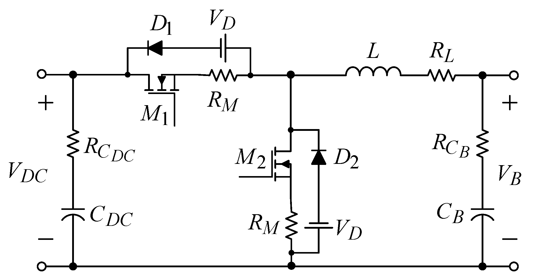
The system configuration of the DC micro-grid is shown in Figure 1. The developed battery energy storage system consists of the battery and the bidirectional DC/DC converter. Figure 2 shows the circuit configuration of the battery charger/discharger. The buck converter and boost converter is combined to form the bidirectional converter. In charging mode, the buck converter is operated with (M1, D2), while in discharging mode, the boost converter is operated with (M2, D1). The non-ideal circuit elements are included in the circuit configuration. The non-ideal elements include the equivalent series resistance (ESR) of the power switch ( R M ), the ESR of the inductor ( R L ), the ESR of the capacitor ( R C B , R C D C ), and the forward conduction voltage of the diode ( V D ). Inductance current i L , DC-link voltage V D C and battery voltage V B are used to determine the duty ratio of the power switches. The feedback signals are sampled by the analog-to-digital converter (ADC). The control of the bidirectional DC/DC converter is digitally realized via the microcontroller Renesas RX62T.

3. Operation Modes and State Equations

3.1. Charging Mode

At charging mode, the power switch M2 is kept off. The duty ratio of the power switch M1 is controlled to regulate the inductance current. When M1 is turned on, the inductance will be magnetized and the inductance current rises. When M1 is turned off, the diode D2 will be forced to turn on. Then the inductance is de-magnetized and the inductance current will fall.
The state space average scheme can be used to find the state equations of charging mode:
[ i ˙ L V ˙ C B ] = [ 1 L ( R L + R R C B R + R C B ) R L ( R + R C B ) R C B ( R + R C B ) 1 C B ( R + R C B ) ] [ i L V C B ] + [ 1 L ( V D C + V D i L R M ) 0 ] D + [ V D L 0 ]
where R is the load resistance and D is the duty ratio of M1. The output is the inductance current:
y = i L = [ 1 0 ] [ i L V C B ]

3.2. Discharging Mode

At discharging mode, the power switch M1 is kept off. The duty ratio of the power switch M2 is controlled to regulate the output voltage. When M2 is turned on, the inductance current rises. When M2 is turned off, the diode D1 will be forced to turn on. Then, the inductance current falls.
The state space average scheme is also used to find the state equations of discharging mode:
[ i ˙ L V ˙ C D C ] = [ 1 L ( R L + R R C D C R + R C D C ) R L ( R + R C D C ) R C D C ( R + R C D C ) 1 C D C ( R + R C D C ) ] [ i L V C D C ]      + [ 1 L [ V D + ( R R C D C R + R C D C R M ) i L + R R + R C D C V C D C ] 1 C D C ( R + R C D C ) i L ] D + [ V B V D L 0 ]
where D is the duty ratio of M1. The output is the DC-link voltage:
y = V D C = [ R R C D C R + R C D C R R + R C D C ] [ i L V C D C ] R R C D C R + R C D C i L D

4. Design of Current Controller and Voltage Controller

In charging/discharging mode, the current/voltage tracking error will converge to zero by defining a new state variable:
x e r r ( t ) = ( r y ( t ) ) d t
where r is desired value of inductance current for charger and output voltage for discharger.
By combining Equations (1), (2) and (5), the expanded state equations of the charger can be obtained as:
[ i ˙ L V ˙ C B x ˙ e r r ] = [ 1 L ( R L + R R C B R + R C B ) R L ( R + R C B ) 0 R C B ( R + R C B ) 1 C B ( R + R C B ) 0 R R C B R + R C B R R + R C B 0 ] [ i L V C B x e r r ] + [ 1 L ( V D C + V D i L R M ) 0 0 ] D + [ V D L 0 r ]
y = [ 1 0 0 ] [ i L V C B x e r r ]
Furthermore, by combining Equations (3)–(5), the expanded state equations of the discharger can be obtained as:
[ i ˙ L V ˙ C D C x ˙ e r r ] = [ 1 L ( R L + R R C D C R + R C D C ) R L ( R + R C D C ) 0 R C D C ( R + R C D C ) 1 C D C ( R + R C D C ) 0 R R C D C R + R C D C R R + R C D C 0 ] [ i L V C D C x e r r ]      + [ 1 L [ V D + ( R R C D C R + R C D C R M ) i L + R R + R C D C V C D C ] 1 C D C ( R + R C D C ) i L R R C D C R + R C D C i L ] D + [ V B V D L 0 r ]
y = V D C = [ R R C D C R + R C D C R R + R C D C 0 ] [ i L V C D C x e r r ] R R C D C R + R C D C i L D
For convenience, Equations (6) and (8) are represented in general state-equation form:
x ˙ ( t ) = A x ( t ) + B u ( t ) + E v ( t )
where v(t) are the disturbances of the system.
In the T-S fuzzy models, the nonlinear BESS are represented by linear sub-systems according to the model rules:
Model rules i: If z1(t) is Mi1 and … and zp(t) is Mip, then
x ˙ ( t ) = A i x ( t ) + B i u ( t )
where u(t) are the control inputs, x(t) are the state variables, Ai, Bi are the state matrices of the sub-systems, Mip is the fuzzy set. In charging mode, iL is chosen as zp(t). In discharging mode, iL, VCDC are chosen as zp(t). The T-S fuzzy system of the BESS can be expressed after defuzzification:
x ˙ ( t ) = i = 1 r h i ( z ( t ) ) { A i x ( t ) + B i u ( t ) }
where:
h i ( z ( t ) ) = j = 1 r M i j ( z j ( t ) ) i = 1 r j = 1 r M i j ( z j ( t ) )
and Mij(zj(t)) is the grad of membership.
The PDC controllers of the BESS are expressed as:
Control rules i: If Z1(t) is Mi1 and … and zp(t) is Mip, then
u ( t ) = i = 1 r h i ( z ( t ) ) F i x ( t )
By substituting (14) into (12), the close-loop system are obtained:
x ˙ ( t ) = i = 1 r j = 1 r h i ( z ( t ) ) h j ( z ( t ) ) { A i B i F j } x ( t )
According to state Equation (10), the BESS T-S fuzzy system with disturbances is found:
x ˙ ( t ) = i = 1 r h i ( z ( t ) ) { A i x ( t ) + B i u ( t ) + E i v ( t ) } y ( t ) = i = 1 r h i ( z ( t ) ) C i x ( t )
To suppress the disturbances, the H performance index is defined:
sup v ( t ) 2 0 y ( t ) 2 v ( t ) 2 γ , 0 γ 1
where γ is the disturbance suppression ability index.
To analyze the stability of the designed current and voltage controller, Lyapunov theorem [19] is applied to find the following LMI condition:
[ X A i T M j T B i T + A i X B i M j E i X C i T E i T γ 2 I 0 C j X 0 I ] < 0 , i j
where X is a positive definite matrix and X = P−1, Mj = FjX.

5. Results and Discussions

Table 1 lists the specifications of the BESS.
For buck mode, the H performance index is selected as γ = 0.7 . For boost mode, the H performance index is selected as γ = 0.8 . The controller gains F i are obtained by using the LMI toolbox in MATLAB.

5.1. Charging Mode

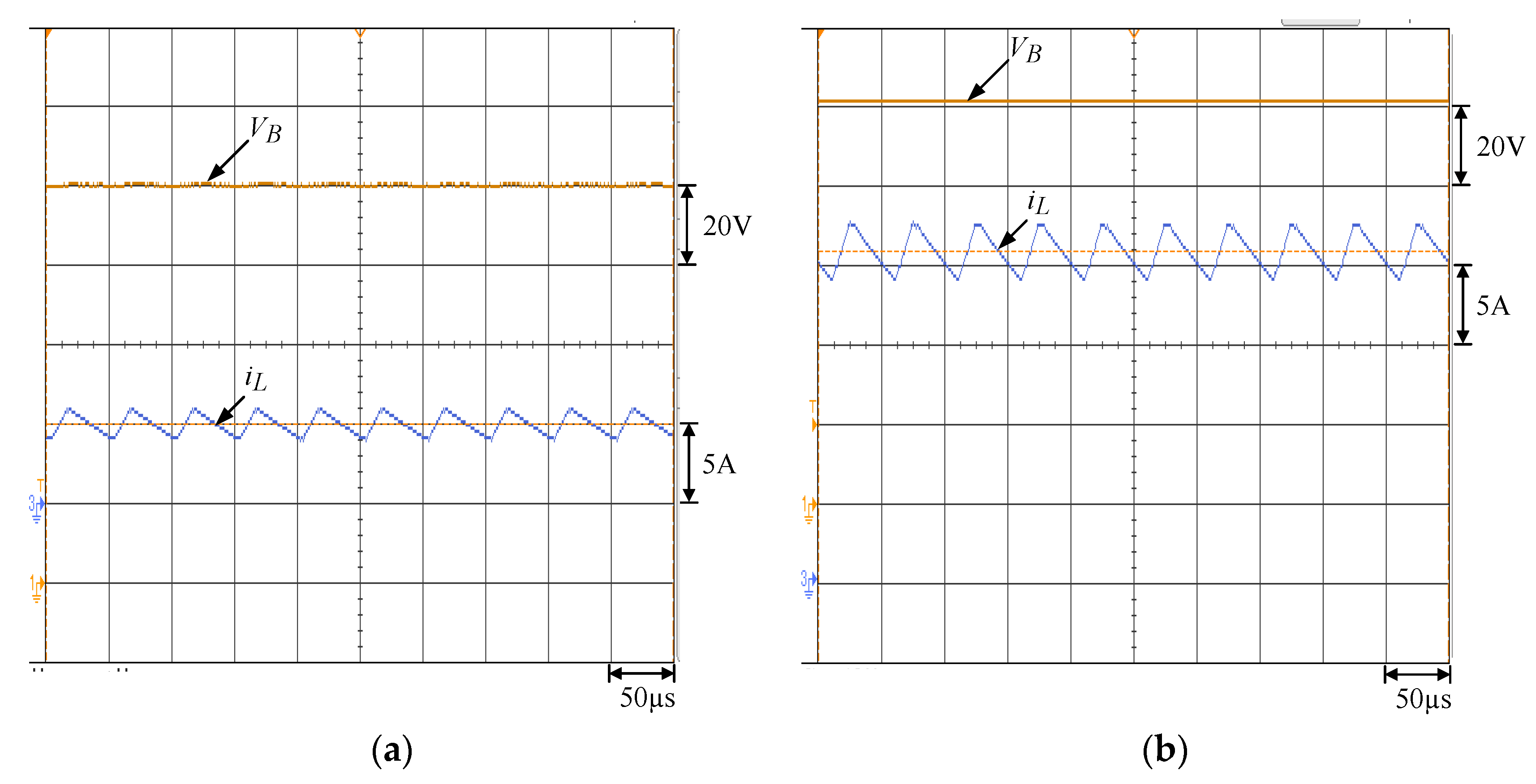
The load resistance is constant and the input voltage VDC is 380 V. The current commands are 5 A and 20 A. The inductance current and battery voltage at current command 5 A, load = 20 Ù (500 W), and current command 20 A, load = 5 Ù (2 kW) are shown in Figure 3a,b, respectively. It can be found that the inductance current can accurately track the command.
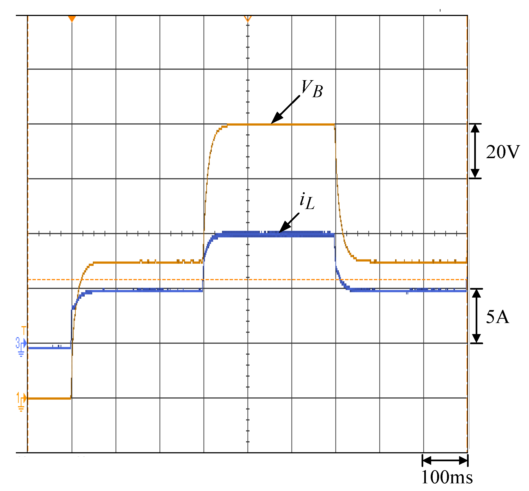
Next, the load is constant (10 Ù) and the input voltage VDC is also 380 V. The current command is variable 5 A → 10 A → 5 A. Figure 4 shows the inductance current and battery voltage with current command variation. It is clear that the inductance current tracks the command accurately.

5.2. Discharging Mode

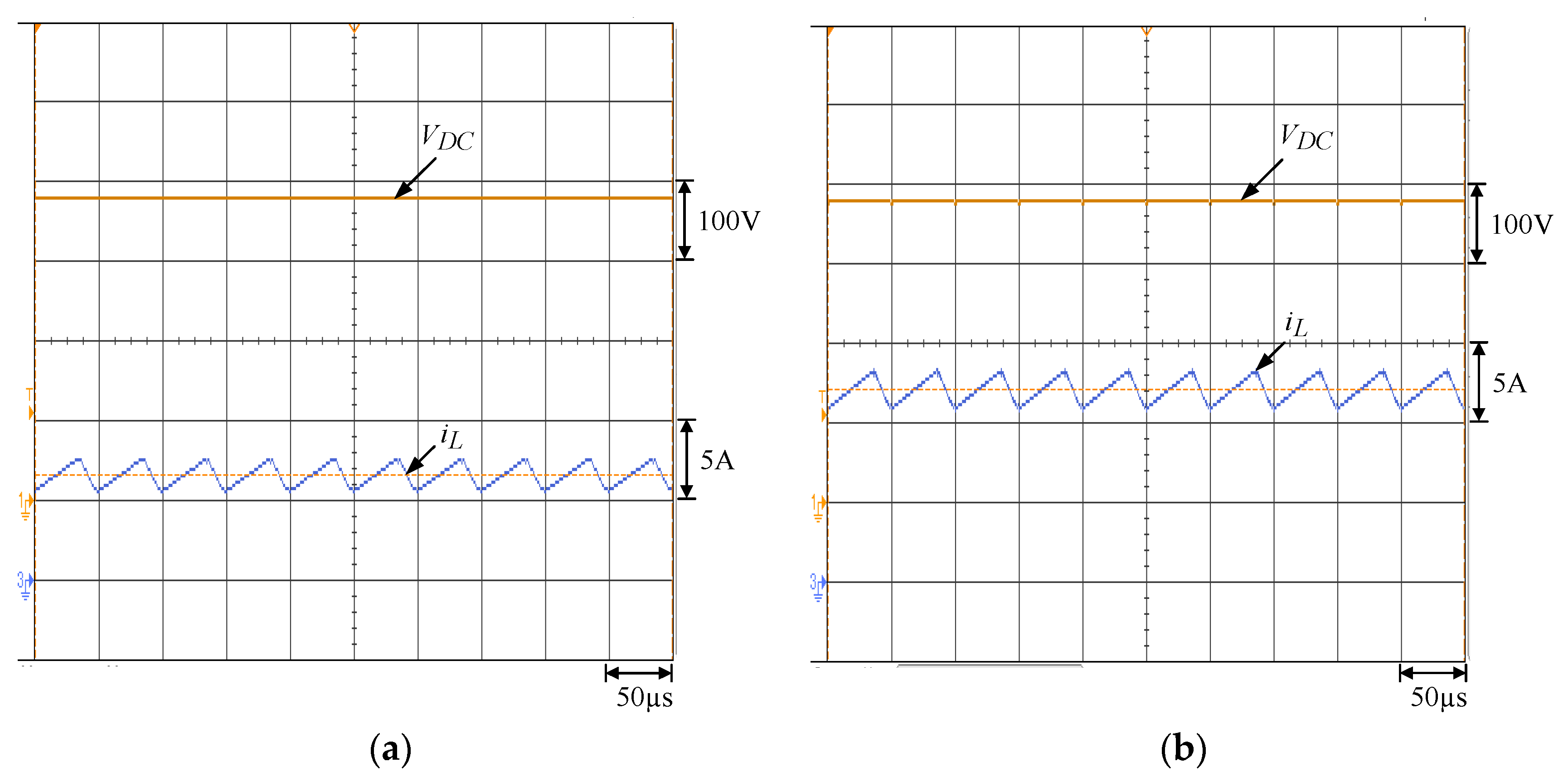
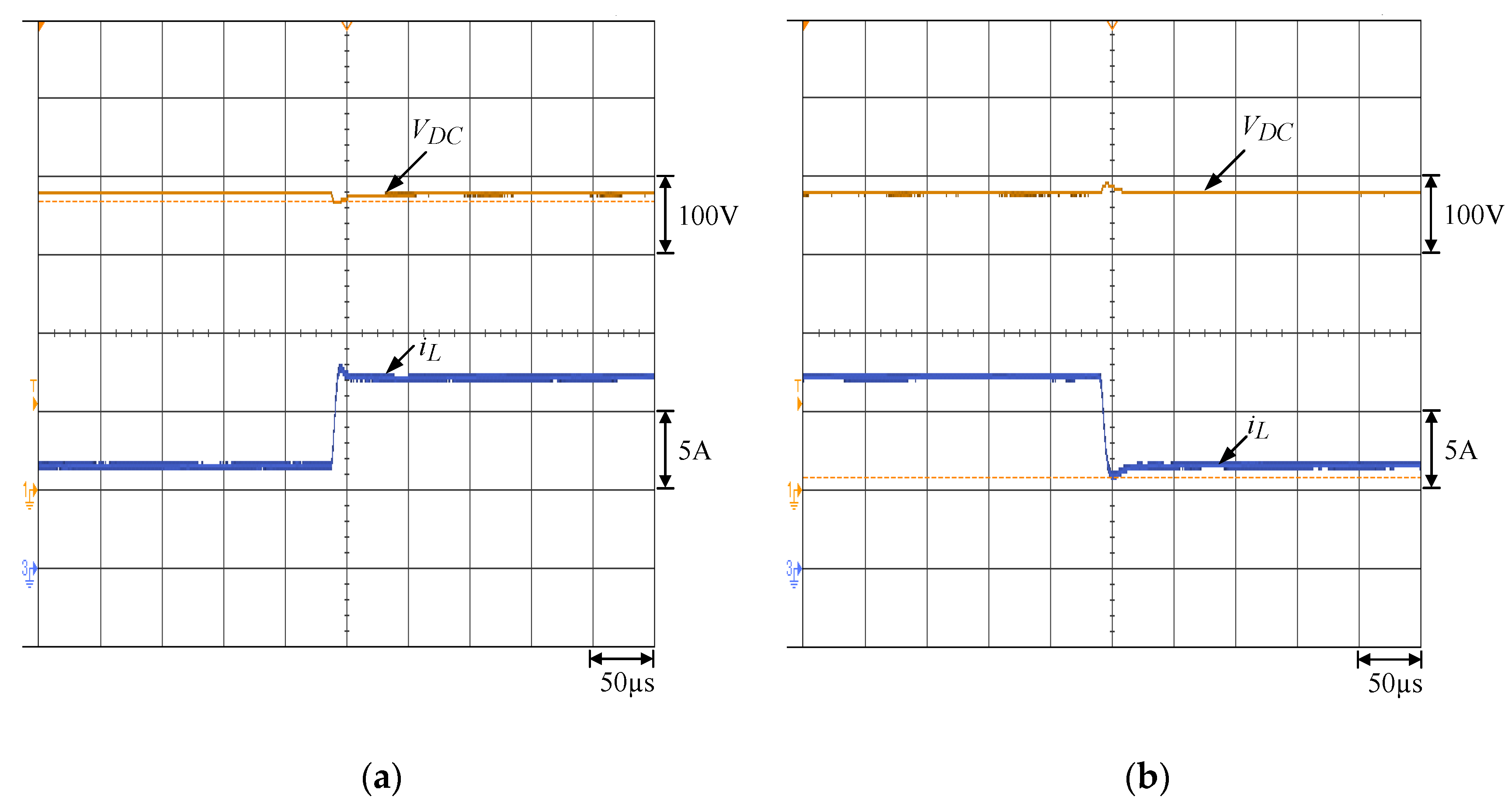
The load resistance is constant and the input battery voltage VB is 100 V. Figure 5a,b shows the inductance current and DC-link voltage at load = 250 Ù (577.6 W) and 135.7 Ù (1.06 kW), respectively. It is obvious that the DC-link voltage can exactly track the command 380 V.
Next, the input voltage VB is 100 V, and the load is variable 250 Ù → 135.7 Ù → 250 Ù. Figure 6a,b shows the inductance current and DC-link voltage under load variation 300 Ù → 150 Ù and 150 Ù → 300 Ù. It can be seen that the DC-link voltage is well regulated under load variation.

6. Conclusions

A battery energy storage system in DC micro-grid systems is designed and implemented. T-S Fuzzy current control and voltage control of the BESS is introduced. The system stability with disturbance suppression ability is analyzed and shown. The performance of the current controller and voltage controller is verified via experimental results.

Author Contributions

The authors contributed equally to this work.

Funding

This research was supported by the Ministry of Science and Technology, Taiwan, under the Grant of MOST 106-2221-E-194-037.

Conflicts of Interest

The authors declare no conflict of interest.

References

  1. Carrizosa, M.J.; Arzandé, A.; Navas, F.D.; Damm, G.; Vannier, J.-C. A control strategy for multiterminal DC grids with renewable production and storage devices. IEEE Trans. Sustain. Energy 2018, 9, 930–939. [Google Scholar] [CrossRef]
  2. Dahmani, O.; Bourguet, S.; Machmoum, M.; Guerin, P.; Rhein, P.; Josse, L. Optimization and reliability evaluation of an offshore wind farm architecture. IEEE Trans. Sustain. Energy 2017, 8, 542–550. [Google Scholar] [CrossRef]
  3. Sharma, S.K.; Chandra, A.; Saad, M.; Lefebvre, S.; Asber, D.; Lenoir, L. Voltage flicker mitigation smart loads with high penetration of renewable energy in distribution systems. IEEE Trans. Sustain. Energy 2017, 8, 414–424. [Google Scholar] [CrossRef]
  4. Sahoo, S.K.; Sinha, A.K.; Kishore, N.K. Control techniques in AC, DC, and hybrid AC-DC microgrid: A review. IEEE J. Emerg. Sel. Top. Power Electron. 2018, 6, 738–759. [Google Scholar] [CrossRef]
  5. Kim, J.; Guerrero, J.M.; Rodriguez, P.; Teodorescu, R.; Nam, K. Mode adaptive droop control with virtual output impedances for an inverter-based flexible AC microgrid. IEEE Trans. Power Electron. 2011, 26, 689–701. [Google Scholar] [CrossRef]
  6. Han, R.; Meng, L.; Ferrari-Trecate, G.; Coelho, E.A.A.; Vasquez, J.C.; Guerrero, J.M. Containment and consensus-based distributed coordination control to achieve bounded voltage and precise reactive power sharing in islanded AC microgrids. IEEE Trans. Ind. Appl. 2017, 53, 5187–5199. [Google Scholar] [CrossRef]
  7. Wang, M.-H.; Mok, K.-T.; Tan, S.-C.; Hui, S.Y. Multifunctional DC electric springs for improving voltage quality of DC grids. IEEE Trans. Smart Grid 2018, 9, 2248–2258. [Google Scholar] [CrossRef]
  8. Kumar, M.; Srivastava, S.C.; Singh, S.N. Control strategies of a DC microgrid for grid connected and islanded operations. IEEE Trans. Smart Grid 2015, 6, 1558–1601. [Google Scholar] [CrossRef]
  9. Radwan, A.A.A.; Mohamed, Y.A.-R.I. Linear active stabilization of converter-dominated DC microgrids. IEEE Trans. Smart Grid 2012, 3, 203–216. [Google Scholar] [CrossRef]
  10. Abeywardana, D.B.W.; Hredzak, B.; Agelidis, V.G. A fixed-frequency sliding mode controller for a boost-inverter-based battery-supercapacitor hybrid energy storage system. IEEE Trans. Power Electron. 2017, 32, 668–680. [Google Scholar] [CrossRef]
  11. Ciccarelli, F.; Iannuzzi, D.; Kondo, K.; Fratelli, L. Line-voltage control based on wayside energy storage systems for tramway networks. IEEE Trans. Power Electron. 2016, 31, 884–899. [Google Scholar] [CrossRef]
  12. Akter, M.P.; Mekhilef, S.; Tan, N.M.L.; Akagi, H. Modified model predictive control of a bidirectional AC-DC converter based on Lyapunov function for energy storage systems. IEEE Trans. Ind. Electron. 2016, 63, 704–715. [Google Scholar] [CrossRef]
  13. Cacciato, M.; Nobile, G.; Scarcella, G.; Scelba, G. Real-time model-based estimation of SOC and SOH for energy storage systems. IEEE Trans. Power Electron. 2017, 32, 794–803. [Google Scholar] [CrossRef]
  14. Takagi, T.; Sugeno, M. Fuzzy identification of systems and its applications to modeling and control. IEEE Trans. Syst. Man Cybern. 1985, SMC-1, 116–132. [Google Scholar] [CrossRef]
  15. Lam, H.K.; Leung, F.H.F. LMI-based stability and performance conditions for continuous-time nonlinear systems in Takagi-Sugeno’s form. IEEE Trans. TSMCB 2007, 37, 1396–1406. [Google Scholar] [CrossRef]
  16. Tanaka, K.; Sugeno, M. Stability analysis and design of fuzzy control systems. Fuzzy Sets Syst. 1992, 45, 135–156. [Google Scholar] [CrossRef]
  17. Lian, K.Y.; Liou, J.J.; Huang, C.Y. LMI-based integral fuzzy control of DC-DC converters. IEEE Trans. Fuzzy Syst. 2006, 14, 71–80. [Google Scholar] [CrossRef]
  18. Mehran, K.; Giaouris, D.; Zahawi, B. Stability analysis and control of nonlinear phenomena in boost converters using model-based Takagi-Sugeno fuzzy approach. IEEE Trans. Circuits Syst. I Reg. Pap. 2010, 57, 200–212. [Google Scholar] [CrossRef]
  19. Chang, Y.C.; Chen, C.H.; Zhu, Z.C.; Huang, Y.W. Speed control of the surface-mounted permanent-magnet synchronous motor based on Takagi-Sugeno fuzzy models. IEEE Trans. Power Electron. 2016, 31, 6504–6510. [Google Scholar] [CrossRef]
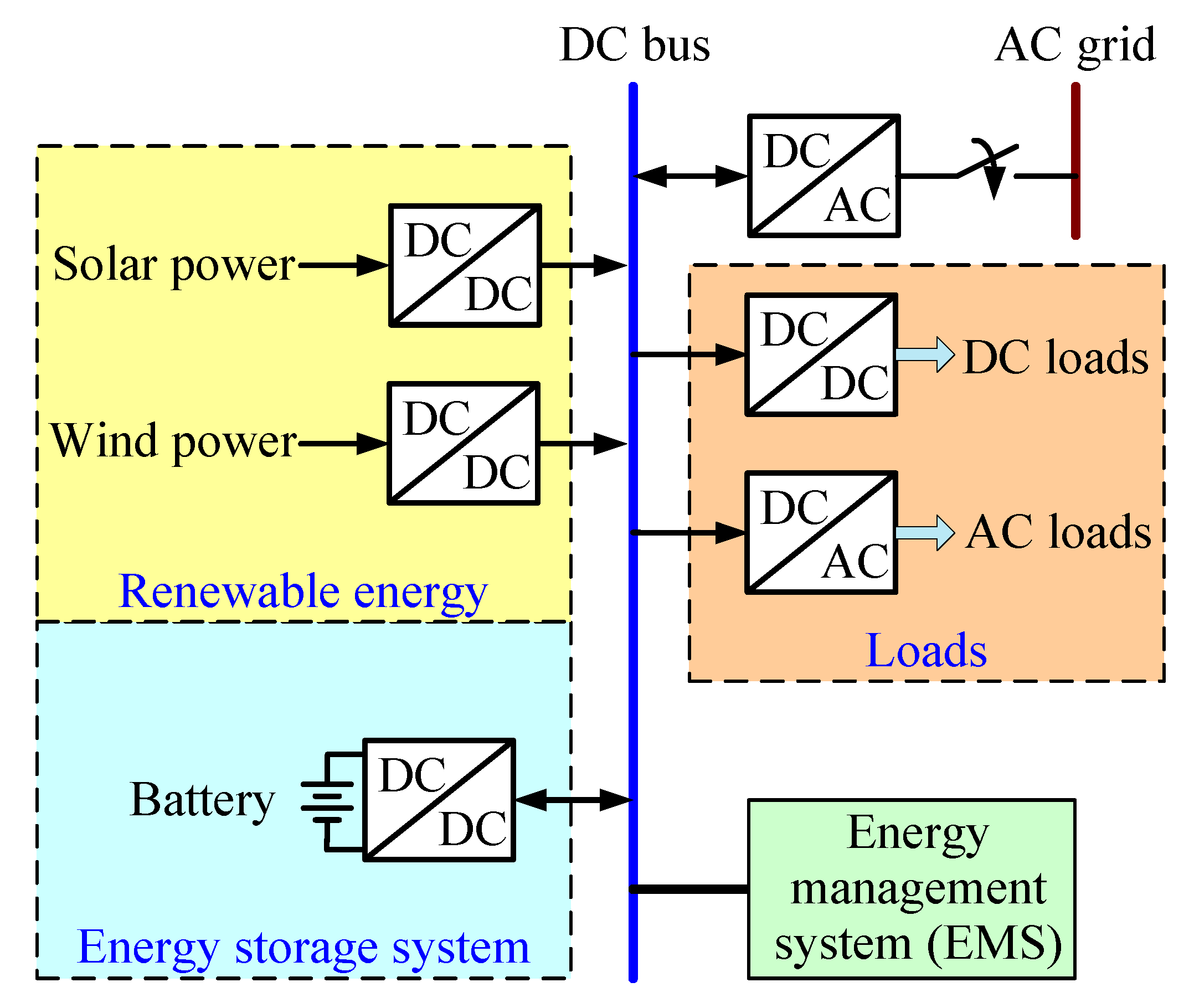
Figure 1. System configuration of the DC micro-grid.
Energies 11 01566 g001
Figure 2. Circuit configuration of the battery charger/discharger.
Energies 11 01566 g002
Figure 3. Inductance current and battery voltage at constant load resistance: (a) current command 5 A, 20 Ù (500 W); (b) current command 20 A, 5 Ù (2 kW).
Energies 11 01566 g003
Figure 4. Inductance current and battery voltage with current command variation 5 A → 10 A → 5 A (load 10 Ù).
Energies 11 01566 g004
Figure 5. Inductance current and DC-link voltage at constant load: (a) 250 Ù (577.6 W); (b) 135.7 Ù (1.06 kW).
Energies 11 01566 g005
Figure 6. Inductance current and DC-link voltage under load variation: (a) 250 Ù → 135.7 Ù; (b) 135.7 Ù → 250 Ù.
Energies 11 01566 g006
Table 1. Specifications of the BESS.
Rated power2 kWVD1.5 V
Inductance1.97 mHRM0.079 Ù
Input voltage380 V (DC)Input capacitance560 µF
Output voltage100 V (DC)Output capacitance440 µF