Mitigation of Power Quality Issues Due to High Penetration of Renewable Energy Sources in Electric Grid Systems Using Three-Phase APF/STATCOM Technologies: A Review


 ,
,  ,
,  , and
, and
Abstract
1. Introduction
2. Harmonics and International Standards
3. Methods for Mitigating Harmonics
3.1. Shunt PFs
- -
- PFs require a separate filter for each harmonic current, and their filtering range is limited.
- -
- PFs allow only one component (either a harmonic or a fundamental current component) to pass at a time.
- -
- Large amounts of harmonic current saturate or overload the filter and cause series resonance with the AC source, thereby resulting in excessive harmonic flow into the PFs.
- -
- PFs amplify source-side harmonic contents because of the impedance in the source of parallel and series negative resonances between the grid and the filter [29].
- -
- The design parameters of PFs in an AC system depend on the system operating frequency, which changes around its nominal value according to variable load conditions.
- -
- PFs only eliminate frequencies to which they are tuned, thus resulting in limited compensation, large size, and tuning issues.
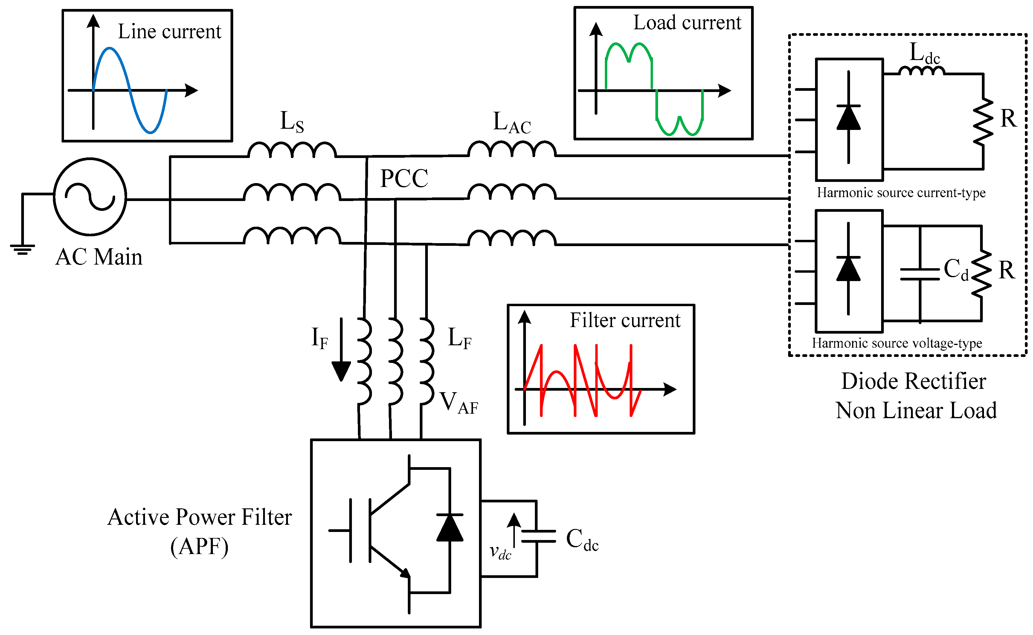
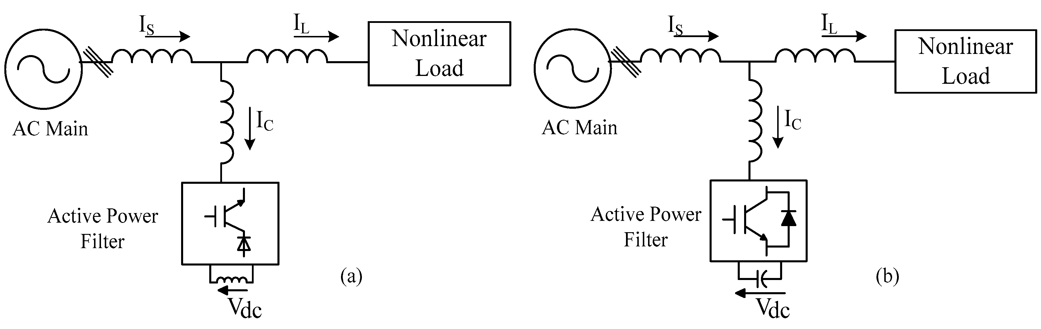
3.2. Shunt APFs
3.3. STATCOM
3.3.1. Multilevel PV-STATCOM Applications in Grid-Connected Systems
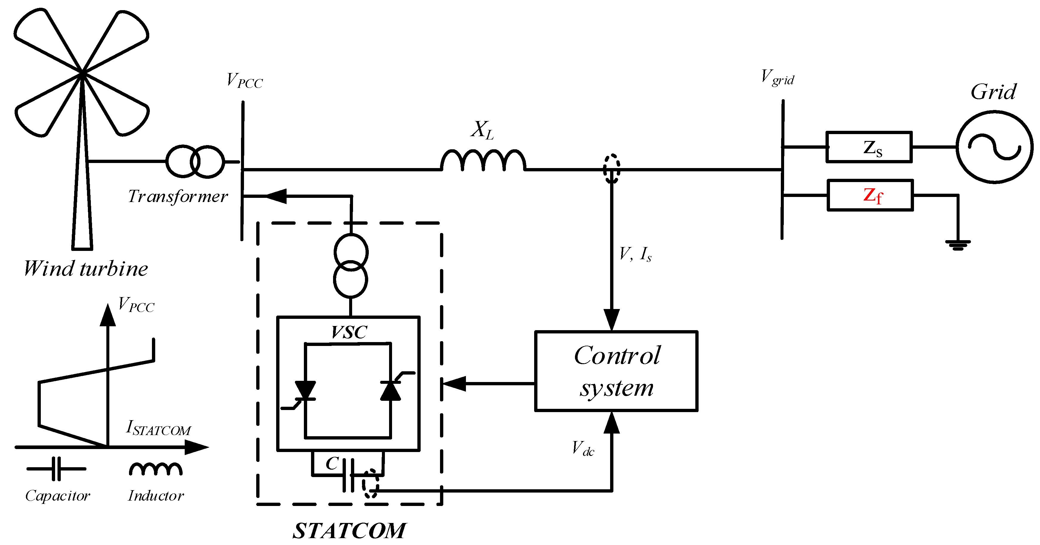
3.3.2. Wind Turbine STATCOM (WT-STATCOM) Applications in Grid-Connected Systems
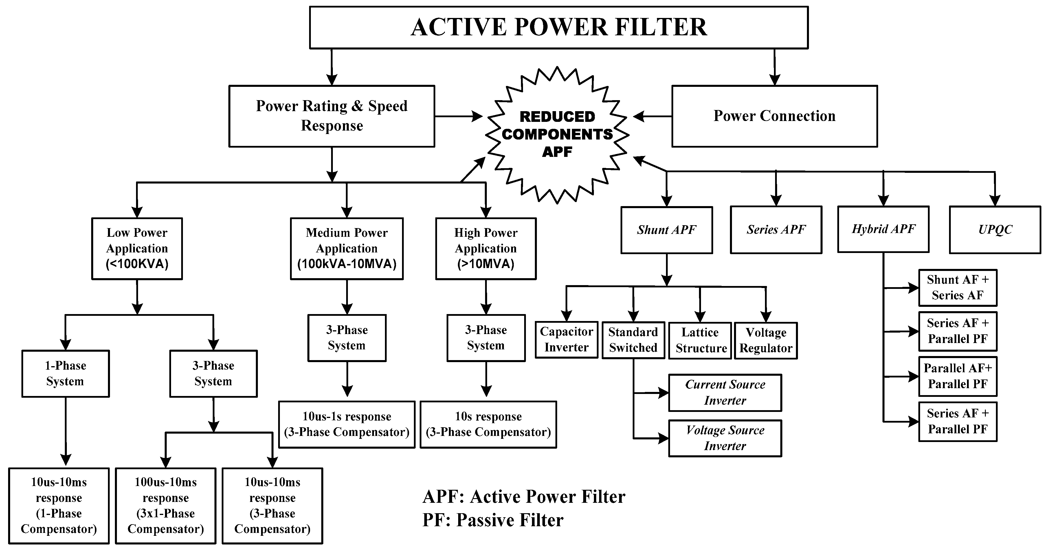
4. Standard Classification of Shunt APFs
Shunt Hybrid APFs
- -
- The initial installation cost is high.
- -
- The control structure and design are considerably complex. Moreover, the increased harmonics and losses complicate filter control.
- -
- With rapid dynamic current response and high-power rating system demand, the APF presents a design trade-off.
5. Advanced Classification of APF/STATCOM
5.1. AC–AC Power Converter Topology
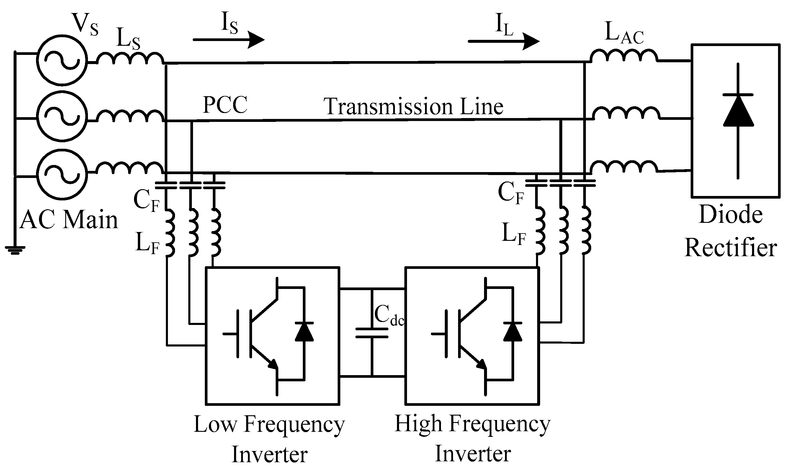
5.2. Parallel-Inverter APF Topology
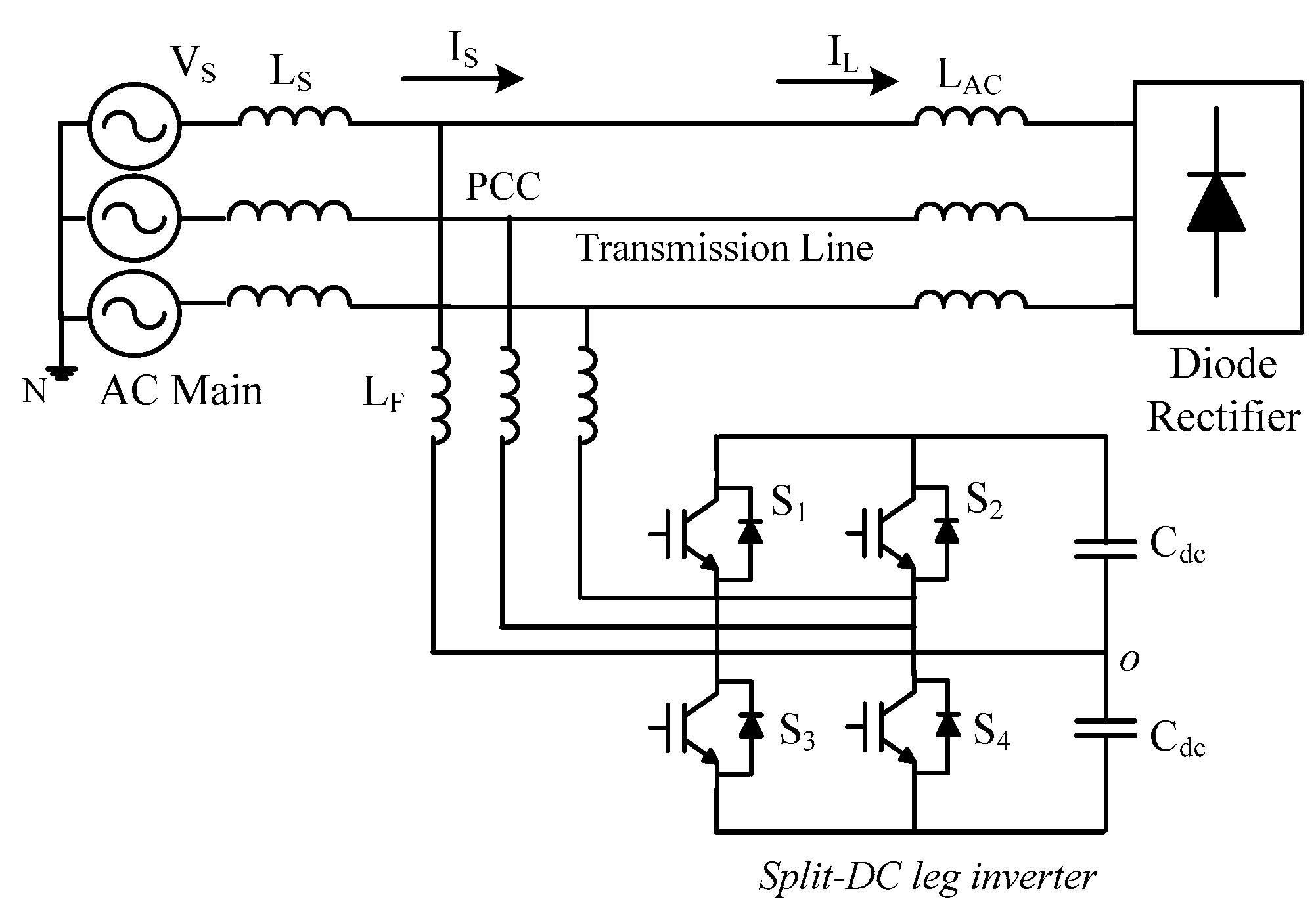
5.3. Split DC-Leg Inverter Topology
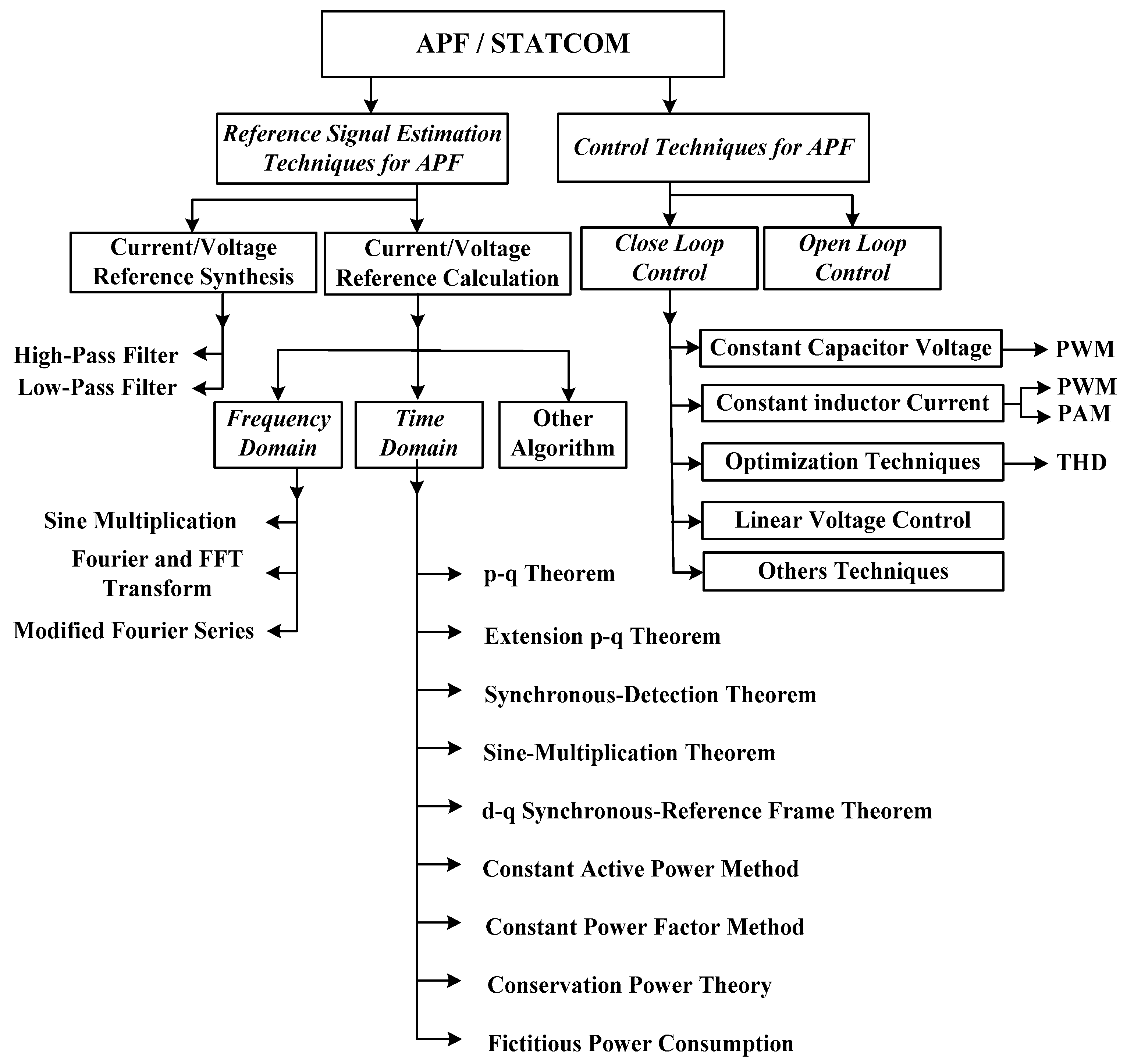
6. APFs/STATCOM Control Techniques
7. Advanced Control Techniques for APFs/STATCOM
7.1. Sinusoidal Pulse Width Modulation
7.2. Space Vector Pulse Width Modulation
8. Performance Evaluation of APF/STATCOM System
9. Key Analysis on Configuration and Control Structure
9.1. Limitations in Configuration Structure
- -
- In B4 inverters, the third phase is connected clearly to the middle point or neutral point of the DC-link capacitors. The DC-bus current directly charges one of the capacitors and discharges the other. These dynamics unbalance current and voltage loading between the capacitors that discharge at a faster rate than the other, thus causing high current ripple in the imbalanced output waveform [206].
- -
- To compensate for the DC-bus voltage fluctuation issues [207], the removed single-leg terminal is connected to the negative terminal of the DC-bus PWM-VSI inverter and stops the imbalanced charging of the DC-link capacitors. Furthermore, the AC film capacitor stores the power ripples connected to the AC terminals to stop the flow of decoupling power ripples and provide balanced output currents and voltages [208].
- -
- A large DC-link voltage variation is shown in B8 split DC-leg converter applications. Both systems are operated at the same frequency and synchronized; thus, no fundamental current flows through the shared DC link. This outcome is a limitation in addition to the low AC voltage of the individual B4 power converter coupled with the shared DC-link capacitor.
- -
- In the three-phase system, a phase circulating current [209] flows through the DC-link capacitors. Thus, the capacitors are exposed to low-frequency harmonics, thereby limiting the use of high DC-link capacitor values. The AC–AC power converter configuration presents superior overall performance than the DC-bus midpoint configuration in terms of low THD and harmonic compensation capability because of the balanced current and voltage, as well as the minimum current ripple in the imbalanced output waveform.
9.2. Limitations in Control Structure Techniques
- -
- The need for voltage feed-forward and cross-coupling in SRF is the main limitation of the control structure. The phase angle of the grid voltage is required to start the control operation.
- -
- In the stationary reference frame, the PR controller reduces the complexity of the control structure in terms of current regulation as it has no need of the phase angle, unlike the dq-frame.
- -
- The adaptive band hysteresis controller increases the complexity of the control structure in the natural reference frame. However, the deadbeat controller simplifies the control scheme. Therefore, an individual control is required in each phase in case of individual phase PLLs and grid voltage to generate the current reference.
- -
- The hysteresis and deadbeat controllers do not consider low-order harmonics in the implementation process in harmonic compensators due to their fast dynamics.
- -
- In practical structures, both controllers require a sampling capability’s hardware to compensate the positive sequence and need two filters, two transformation modules, and one controller, thus limiting its practical application in the dq-frame.
- -
9.3. Key Findings
- (1)
- In parallel inverter topology, the output voltage per phase at different frequencies generates transitions, which block the forbidden states. This voltage effectively limits the range of reference amplitudes and phase shifts.
- (2)
- Generally, in reduced switch count power converters, the modulation strategy adopted is SPWM to switch and compensate for the DC-bus voltage fluctuation issues [214]. By contrast, in reduced switch count converters, the phase shift does not track the three-phase balance reference signal in the symmetry order.
- (3)
- Switch reduction generally leads to interdependencies between AC input and output frequencies, unlike full-bridge converters. This restriction limits the references for modulation in operating the power converters at the same frequency. Voltage doubling and semiconductor stress are not issues in the B4 converter, unlike in the nine-switch H6 converter, because of the favorable maximum modulation ratio of unity [215].
- (4)
- Reduced switch count (four-switch) topologies face more limitations in their switching states than conventional six-switch converters. Findings indicate that the removed leg terminal that is connected to either the upper positive DC-link terminal or the lower negative DC-link terminal is not achievable.
- (5)
- In the B6 converter, two switching states, (0, 0) and (1, 1), are stated as zero vectors, which stop the flow of the current toward the load. In the B4 converter, the current flows even in zero-vector states. Therefore, in two other switching states, (0, 1) and (1, 0), the resulting uncontrolled current flows through the common phase because of the direct connection between the DC-link capacitor and the AC terminal.
- (6)
- The PLL synchronizes the power inverter modulation to the power grid and provides freedom in designing the modulation index caused by phasing the angle in between the grids and by modulating waves to adjust the maximum magnitude for unity output.
- (7)
- Eliminating the active switches creates an unequal thermal distribution among the remaining switches at the expense of reduced structure, conduction losses, switching losses, and low system cost.
- (8)
- In the split converter, the third-phase current flows directly through DC-link capacitors, thus exposing the converter to low-frequency harmonics, which need a high-value-rated capacitor.
- (9)
- In the two-leg rectifier (multiply by 2/pi = 0.6), the output power gain is lower than that of the three-leg rectifier (multiply by 1.6), thereby increasing the current rating of the active switching components.
10. Upcoming Trends
11. Conclusions
Author Contributions
Acknowledgments
Conflicts of Interest
Abbreviations
| APF | Active power filters |
| B4 | Four-switch inverter |
| CSI | Current-fed-type inverters |
| CHB | Cascaded H-bridge |
| DFT | Discrete Fourier transform |
| DSP | Digital signal processor |
| dSpace | Digital Signal Processor for Applied and Control Engineering |
| DSTATCOM | Distribution STATCOM |
| DQ | Synchronous Fundamental Frame |
| DVR | Dynamic voltage restorer |
| ESS | Energy storage system |
| FACTS | Flexible AC transmission system |
| FFT | Fast Fourier transform |
| GPGA | Field programmable gate array |
| HAPFs | Hybrid APF |
| HF | High frequency |
| HPF | High pass filter |
| HV | High voltage |
| IEEE | Institute of Electrical and Electronics Engineers |
| IEC | International Electro-technical Commission |
| IGBT | Insulated-gate bipolar transistors |
| ITC | Indirect torque control |
| Ki | Integral gain |
| Kp | Proportional gain |
| LPF | Low pass filter |
| LVRT | Low-voltage ride through |
| MLI | Multilevel inverter |
| MOSFET | Metal-oxide-semiconductor field-effect transistor |
| MPP | Maximum power point |
| PCC | Point of common coupling |
| PF | Passive filter |
| PI | Proportional integral controller |
| PLL | Phase locked loop |
| PQ | Instantaneous power theory |
| PV | Photovoltaic |
| PWM | Pulse width modulation |
| RC | Repetitive Controller |
| RDFT | Recursive discrete Fourier Transform |
| SAPF | Shunt active power filter |
| SBD | Schottky barrier diode |
| SHE | Selective harmonic elimination |
| SiC | Silicon carbide |
| SMC | Sliding Mode Control |
| SOFC | Solid oxide fuel call |
| SPWM | Sinusoidal Pulse Width Modulation |
| SRF | Synchronous-reference-frame |
| STATCOM | static compensator |
| SVC | Static volt-ampere reactive VAR compensator |
| SVM | Space vector modulation |
| SVPWM | Space vector Pulse Width Modulation |
| TCR | Thyristor-controlled resistor |
| THD | Total Harmonic Distortion |
| UPQC | Unified power quality conditioner (UPQC) |
| VSC | Voltage Source Converter |
| VSI | Voltage-fed-type inverters |
| WT | Wind turbine |
| 1P2W | Single-phase two-wire |
| 3P3W | Three-phase three-wire |
| 3P4W | Three-phase four-wire |
| 3P4L | Three phase four-leg |
References
- Singh, B.; Al-Haddad, K.; Chandra, A. A review of active filters for power quality improvement. IEEE Trans. Ind. Electron. 1999, 46, 960–971. [Google Scholar] [CrossRef]
- Hamadi, A.; Rahmani, S.; Al-Haddad, K. A Hybrid Passive Filter Configuration for VAR Control and Harmonic Compensation. IEEE Trans. Ind. Electron. 2010, 57, 2419–2434. [Google Scholar] [CrossRef]
- Bhattacharya, A.; Chakraborty, C.; Bhattacharya, S. Shunt compensation. IEEE Ind. Electron. Mag. 2009, 3, 38–49. [Google Scholar] [CrossRef]
- Sirjani, R.; Rezaee Jordehi, A. Optimal placement and sizing of distribution static compensator (D-STATCOM) in electric distribution networks: A review. Renew. Sustain. Energy Rev. 2017, 77, 688–694. [Google Scholar] [CrossRef]
- Beres, R.N.; Wang, X.; Liserre, M.; Blaabjerg, F.; Bak, C.L. A review of passive power filters for three-phase grid-connected voltage-source converters. IEEE J. Emerg. Sel. Top. Power Electron. 2016, 4, 54–69. [Google Scholar] [CrossRef]
- Ringwood, J.V.; Simani, S. Overview of modelling and control strategies for wind turbines and wave energy devices: Comparisons and contrasts. Annu. Rev. Control 2015, 40, 27–49. [Google Scholar] [CrossRef]
- Ahmed, K.H.; Finney, S.J.; Williams, B.W. Passive filter design for three-phase inverter interfacing in distributed generation. In Proceedings of the Compatibility in Power Electronics, Gdansk, Poland, 29 May–1 June 2007; pp. 1–9. [Google Scholar]
- Lam, C.S.; Choi, W.H.; Wong, M.C.; Han, Y.D. Adaptive DC-Link Voltage-Controlled Hybrid Active Power Filters for Reactive Power Compensation. IEEE Trans. Power Electron. 2012, 27, 1758–1772. [Google Scholar] [CrossRef]
- Espi, J.; Garcia-Gil, R.; Castello, J. Capacitive Emulation for LCL-Filtered Grid-Connected Converters. Energies 2017, 10, 930. [Google Scholar] [CrossRef]
- Litran, S.P.; Salmeron, P. Analysis and design of different control strategies of hybrid active power filter based on the state model. IET Power Electron. 2012, 5, 1341–1350. [Google Scholar] [CrossRef]
- Prakash Mahela, O.; Gafoor Shaik, A. Topological aspects of power quality improvement techniques: A comprehensive overview. Renew. Sustain. Energy Rev. 2016, 58, 1129–1142. [Google Scholar] [CrossRef]
- Mithulananthan, N.; Canizares, C.A.; Reeve, J.; Rogers, G.J. Comparison of PSS, SVC, and STATCOM controllers for damping power system oscillations. IEEE Trans. Power Syst. 2003, 18, 786–792. [Google Scholar] [CrossRef]
- Colak, I.; Kabalci, E.; Fulli, G.; Lazarou, S. A survey on the contributions of power electronics to smart grid systems. Renew. Sustain. Energy Rev. 2015, 47, 562–579. [Google Scholar] [CrossRef]
- Singh, B.; Solanki, J. A Comparison of Control Algorithms for DSTATCOM. IEEE Trans. Ind. Electron. 2009, 56, 2738–2745. [Google Scholar] [CrossRef]
- Singh, B.; Mukherjee, V.; Tiwari, P. A survey on impact assessment of DG and FACTS controllers in power systems. Renew. Sustain. Energy Rev. 2015, 42, 846–882. [Google Scholar] [CrossRef]
- Tokiwa, A.; Yamada, H.; Tanaka, T.; Watanabe, M.; Shirai, M.; Teranishi, Y. New Hybrid Static VAR Compensator with Series Active Filter. Energies 2017, 10, 1617. [Google Scholar] [CrossRef]
- Qazi, S.H.; Mustafa, M.W. Review on active filters and its performance with grid connected fixed and variable speed wind turbine generator. Renew. Sustain. Energy Rev. 2016, 57, 420–438. [Google Scholar] [CrossRef]
- Tareen, W.U.K.; Mekhilef, S.; Nakaoka, M. A transformerless reduced switch counts three-phase APF-assisted smart EV charger. In Proceedings of the 2017 IEEE Applied Power Electronics Conference and Exposition (APEC), Tampa, FL, USA, 26–30 March 2017; pp. 3307–3312. [Google Scholar]
- Jordehi, A.R. Particle swarm optimisation (PSO) for allocation of FACTS devices in electric transmission systems: A review. Renew. Sustain. Energy Rev. 2015, 52, 1260–1267. [Google Scholar] [CrossRef]
- Shmilovitz, D. On the definition of total harmonic distortion and its effect on measurement interpretation. IEEE Trans. Power Deliv. 2005, 20, 526–528. [Google Scholar]
- Barros, J.; Diego, R.I. A review of measurement and analysis of electric power quality on shipboard power system networks. Renew. Sustain. Energy Rev. 2016, 62, 665–672. [Google Scholar] [CrossRef]
- Lascu, C.; Asiminoaei, L.; Boldea, I.; Blaabjerg, F. High Performance Current Controller for Selective Harmonic Compensation in Active Power Filters. IEEE Trans. Power Electron. 2007, 22, 1826–1835. [Google Scholar] [CrossRef]
- Kanjiya, P.; Khadkikar, V.; Zeineldin, H.H. Optimal Control of Shunt Active Power Filter to Meet IEEE Std. 519 Current Harmonic Constraints Under Nonideal Supply Condition. IEEE Trans. Ind. Electron. 2015, 62, 724–734. [Google Scholar] [CrossRef]
- Bollen, M.H. What is power quality? Electr. Power Syst. Res. 2003, 66, 5–14. [Google Scholar] [CrossRef]
- Mahela, O.P.; Shaik, A.G.; Gupta, N. A critical review of detection and classification of power quality events. Renew. Sustain. Energy Rev. 2015, 41, 495–505. [Google Scholar] [CrossRef]
- Khadem, S.K.; Basu, M.; Conlon, M.F. Parallel operation of inverters and active power filters in distributed generation system—A review. Renew. Sustain. Energy Rev. 2011, 15, 5155–5168. [Google Scholar] [CrossRef]
- Wang, Y.; Kuckelkorn, J.; Zhao, F.-Y.; Spliethoff, H.; Lang, W. A state of art of review on interactions between energy performance and indoor environment quality in Passive House buildings. Renew. Sustain. Energy Rev. 2017, 72, 1303–1319. [Google Scholar] [CrossRef]
- Büyük, M.; Tan, A.; Tümay, M.; Bayındır, K.Ç. Topologies, generalized designs, passive and active damping methods of switching ripple filters for voltage source inverter: A comprehensive review. Renew. Sustain. Energy Rev. 2016, 62, 46–69. [Google Scholar] [CrossRef]
- Wu, J.-C.; Jou, H.-L.; Wu, K.-D.; Hsiao, H.-H. Three-phase four-wire hybrid power filter using a smaller power converter. Electr. Power Syst. Res. 2012, 87, 13–21. [Google Scholar] [CrossRef]
- Bouzelata, Y.; Kurt, E.; Altın, N.; Chenni, R. Design and simulation of a solar supplied multifunctional active power filter and a comparative study on the current-detection algorithms. Renew. Sustain. Energy Rev. 2015, 43, 1114–1126. [Google Scholar] [CrossRef]
- Mehrasa, M.; Pouresmaeil, E.; Zabihi, S.; Rodrigues, E.M.G.; Catalão, J.P.S. A control strategy for the stable operation of shunt active power filters in power grids. Energy 2016, 96, 325–334. [Google Scholar] [CrossRef]
- Mohd Zainuri, M.; Mohd Radzi, M.; Che Soh, A.; Mariun, N.; Abd Rahim, N.; Teh, J.; Lai, C.-M. Photovoltaic Integrated Shunt Active Power Filter with Simpler ADALINE Algorithm for Current Harmonic Extraction. Energies 2018, 11, 1152. [Google Scholar] [CrossRef]
- Qiao, W.; Harley, R.G.; Venayagamoorthy, G.K. Coordinated Reactive Power Control of a Large Wind Farm and a STATCOM Using Heuristic Dynamic Programming. IEEE Trans. Energy Convers. 2009, 24, 493–503. [Google Scholar] [CrossRef]
- De la Villa Jaen, A.; Acha, E.; Exposito, A.G. Voltage Source Converter Modeling for Power System State Estimation: STATCOM and VSC-HVDC. IEEE Trans. Power Syst. 2008, 23, 1552–1559. [Google Scholar] [CrossRef]
- Arsoy, A.B.; Liu, Y.; Ribeiro, P.F.; Wang, F. StatCom-SMES. IEEE Ind. Appl. Mag. 2003, 9, 21–28. [Google Scholar] [CrossRef]
- Pathak, A.K.; Sharma, M.P.; Bundele, M. A critical review of voltage and reactive power management of wind farms. Renew. Sustain. Energy Rev. 2015, 51, 460–471. [Google Scholar] [CrossRef]
- Singh, B.; Saha, R.; Chandra, A.; Al-Haddad, K. Static synchronous compensators (STATCOM): A review. IET Power Electron. 2009, 2, 297–324. [Google Scholar] [CrossRef]
- Adamczyk, A.G.; Teodorescu, R.; Rodriguez, P.; Mukerjee, R.N. FACTS devices for large wind power plants. In Proceedings of the EPE Wind Energy Chapter Symposium, Stafford, UK, 15–16 April 2010. [Google Scholar]
- Belouda, M.; Jaafar, A.; Sareni, B.; Roboam, X.; Belhadj, J. Integrated optimal design and sensitivity analysis of a stand alone wind turbine system with storage for rural electrification. Renew. Sustain. Energy Rev. 2013, 28, 616–624. [Google Scholar] [CrossRef]
- Mahela, O.P.; Shaik, A.G. A review of distribution static compensator. Renew. Sustain. Energy Rev. 2015, 50, 531–546. [Google Scholar] [CrossRef]
- Siemens. Flexible AC Transmission Systems (FACTS), Parallel Compensation, Comprehensive Solutions for Safe and Reliable Grid Operation; Siemens: Munich, Germany, 2016. [Google Scholar]
- Hingorani, N.G. Flexible AC transmission. IEEE Spectr. 1993, 30, 40–45. [Google Scholar] [CrossRef]
- Habur, K.; O’Leary, D. FACTS—Flexible Alternating Current Transmission Systems: For Cost Effective and Reliable Transmission of Electrical Energy; Siemens-World Bank Document-Final Draft Report; Siemens: Erlangen, Germany, 2004. [Google Scholar]
- Norambuena, M.; Rodriguez, J.; Kouro, S.; Rathore, A. A novel multilevel converter with reduced switch count for low and medium voltage applications. In Proceedings of the 2017 IEEE Energy Conversion Congress and Exposition (ECCE), Cincinnati, OH, USA, 1–5 October 2017; pp. 5267–5272. [Google Scholar]
- Vijayaraja, L.; Kumar, S.G.; Rivera, M. A review on multilevel inverter with reduced switch count. In Proceedings of the 2016 IEEE International Conference on Automatica (ICA-ACCA), Curico, Chile, 19–21 October 2016; pp. 1–5. [Google Scholar]
- Vavilapalli, S.; Padmanaban, S.; Subramaniam, U.; Mihet-Popa, L. Power Balancing Control for Grid Energy Storage System in Photovoltaic Applications—Real Time Digital Simulation Implementation. Energies 2017, 10, 928. [Google Scholar] [CrossRef]
- Sridhar, V.; Umashankar, S. A comprehensive review on CHB MLI based PV inverter and feasibility study of CHB MLI based PV-STATCOM. Renew. Sustain. Energy Rev. 2017, 78, 138–156. [Google Scholar] [CrossRef]
- Chang, W.-N.; Liao, C.-H. Design and Implementation of a STATCOM Based on a Multilevel FHB Converter with Delta-Connected Configuration for Unbalanced Load Compensation. Energies 2017, 10, 921. [Google Scholar] [CrossRef]
- Varma, R.K.; Khadkikar, V.; Seethapathy, R. Nighttime Application of PV Solar Farm as STATCOM to Regulate Grid Voltage. IEEE Trans. Energy Convers. 2009, 24, 983–985. [Google Scholar] [CrossRef]
- Varma, R.K.; Rahman, S.A.; Vanderheide, T. New Control of PV Solar Farm as STATCOM (PV-STATCOM) for Increasing Grid Power Transmission Limits During Night and Day. IEEE Trans. Power Deliv. 2015, 30, 755–763. [Google Scholar] [CrossRef]
- Varma, R.K.; Das, B.; Axente, I.; Vanderheide, T. Optimal 24-hr utilization of a PV solar system as STATCOM (PV-STATCOM) in a distribution network. In Proceedings of the 2011 IEEE Power and Energy Society General Meeting, San Diego, CA, USA, 24–29 July 2011; pp. 1–8. [Google Scholar]
- Junbiao, H.; Solanki, S.K.; Solanki, J.; Schoene, J. Study of unified control of STATCOM to resolve the Power quality issues of a grid-connected three phase PV system. In Proceedings of the 2012 IEEE PES Innovative Smart Grid Technologies (ISGT), Washington, DC, USA, 16–20 January 2012; pp. 1–7. [Google Scholar]
- Seo, H.R.; Kim, G.H.; Jang, S.J.; Kim, S.Y.; Park, S.; Park, M.; Yu, I.K. Harmonics and reactive power compensation method by grid-connected Photovoltaic generation system. In Proceedings of the 2009 International Conference on Electrical Machines and Systems, Tokyo, Japan, 15–18 November 2009; pp. 1–5. [Google Scholar]
- Demirdelen, T.; Kayaalp, R.İ.; Tumay, M. Simulation modelling and analysis of modular cascaded multilevel converter based shunt hybrid active power filter for large scale photovoltaic system interconnection. Simul. Model. Pract. Theory 2017, 71, 27–44. [Google Scholar] [CrossRef]
- Varma, R.K.; Rahman, S.A.; Sharma, V.; Vanderheide, T. Novel control of a PV solar system as STATCOM (PV-STATCOM) for preventing instability of induction motor load. In Proceedings of the 2012 25th IEEE Canadian Conference on Electrical and Computer Engineering (CCECE), Montreal, QC, Canada, 29 April–2 May 2012; pp. 1–5. [Google Scholar]
- Toodeji, H.; Farokhnia, N.; Riahy, G.H. Integration of PV module and STATCOM to extract maximum power from PV. In Proceedings of the 2009 International Conference on Electric Power and Energy Conversion Systems, Sharjah, UAE, 10–12 November 2009; pp. 1–6. [Google Scholar]
- Luo, L.; Gu, W.; Zhang, X.-P.; Cao, G.; Wang, W.; Zhu, G.; You, D.; Wu, Z. Optimal siting and sizing of distributed generation in distribution systems with PV solar farm utilized as STATCOM (PV-STATCOM). Appl. Energy 2018, 210, 1092–1100. [Google Scholar] [CrossRef]
- Zeng, Z.; Yang, H.; Zhao, R.; Cheng, C. Topologies and control strategies of multi-functional grid-connected inverters for power quality enhancement: A comprehensive review. Renew. Sustain. Energy Rev. 2013, 24, 223–270. [Google Scholar] [CrossRef]
- Hassaine, L.; Olias, E.; Quintero, J.; Salas, V. Overview of power inverter topologies and control structures for grid connected photovoltaic systems. Renew. Sustain. Energy Rev. 2014, 30, 796–807. [Google Scholar] [CrossRef]
- Karimi, M.; Mokhlis, H.; Naidu, K.; Uddin, S.; Bakar, A.H.A. Photovoltaic penetration issues and impacts in distribution network—A review. Renew. Sustain. Energy Rev. 2016, 53, 594–605. [Google Scholar] [CrossRef]
- Mahmud, N.; Zahedi, A. Review of control strategies for voltage regulation of the smart distribution network with high penetration of renewable distributed generation. Renew. Sustain. Energy Rev. 2016, 64, 582–595. [Google Scholar] [CrossRef]
- Kow, K.W.; Wong, Y.W.; Rajkumar, R.K.; Rajkumar, R.K. A review on performance of artificial intelligence and conventional method in mitigating PV grid-tied related power quality events. Renew. Sustain. Energy Rev. 2016, 56, 334–346. [Google Scholar] [CrossRef]
- Vivas, J.H.; Bergna, G.; Boyra, M. Comparison of multilevel converter-based STATCOMs. In Proceedings of the 2011 14th European Conference on Power Electronics and Applications, Birmingham, UK, 30 August–1 September 2011; pp. 1–10. [Google Scholar]
- Agrawal, R.; Jain, S. Comparison of reduced part count multilevel inverters (RPC-MLIs) for integration to the grid. Int. J. Electr. Power Energy Syst. 2017, 84, 214–224. [Google Scholar] [CrossRef]
- Najjar, M.; Moeini, A.; Bakhshizadeh, M.K.; Blaabjerg, F.; Farhangi, S. Optimal Selective Harmonic Mitigation Technique on Variable DC Link Cascaded H-Bridge Converter to Meet Power Quality Standards. IEEE J. Emerg. Sel. Top. Power Electron. 2016, 4, 1107–1116. [Google Scholar] [CrossRef]
- Haw, L.K.; Dahidah, M.S.A.; Almurib, H.A.F. SHE-PWM Cascaded Multilevel Inverter With Adjustable DC Voltage Levels Control for STATCOM Applications. IEEE Trans. Power Electron. 2014, 29, 6433–6444. [Google Scholar] [CrossRef]
- Song, W.; Huang, A.Q. Fault-Tolerant Design and Control Strategy for Cascaded H-Bridge Multilevel Converter-Based STATCOM. IEEE Trans. Ind. Electron. 2010, 57, 2700–2708. [Google Scholar] [CrossRef]
- Yiqiao, L.; Nwankpa, C.O. A new type of STATCOM based on cascading voltage-source inverters with phase-shifted unipolar SPWM. IEEE Trans. Ind. Appl. 1999, 35, 1118–1123. [Google Scholar] [CrossRef]
- Gultekin, B.; Gercek, C.O.; Atalik, T.; Deniz, M.; Bicer, N.; Ermis, M.; Kose, K.N.; Ermis, C.; Koc, E.; Cadirci, I.; et al. Design and Implementation of a 154-kV ± 50-Mvar Transmission STATCOM Based on 21-Level Cascaded Multilevel Converter. IEEE Trans. Ind. Appl. 2012, 48, 1030–1045. [Google Scholar] [CrossRef]
- Gultekin, B.; Ermis, M. Cascaded Multilevel Converter-Based Transmission STATCOM: System Design Methodology and Development of a 12 kV ± 12 MVAr Power Stage. IEEE Trans. Power Electron. 2013, 28, 4930–4950. [Google Scholar] [CrossRef]
- Nunes, W.; Encarnação, L.; Aredes, M. An Improved Asymmetric Cascaded Multilevel D–STATCOM with Enhanced Hybrid Modulation. Electronics 2015, 4, 311–328. [Google Scholar] [CrossRef]
- De León Morales, J.; Mata-Jiménez, M.T.; Escalante, M.F. Adaptive scheme for DC voltages estimation in a cascaded H-bridge multilevel converter. Electr. Power Syst. Res. 2011, 81, 1943–1951. [Google Scholar] [CrossRef]
- Hatano, N.; Ise, T. Control Scheme of Cascaded H-Bridge STATCOM Using Zero-Sequence Voltage and Negative-Sequence Current. IEEE Trans. Power Deliv. 2010, 25, 543–550. [Google Scholar] [CrossRef]
- Lee, C.T.; Wang, B.S.; Chen, S.W.; Chou, S.F.; Huang, J.L.; Cheng, P.T.; Akagi, H.; Barbosa, P. Average Power Balancing Control of a STATCOM Based on the Cascaded H-Bridge PWM Converter with Star Configuration. IEEE Trans. Ind. Appl. 2014, 50, 3893–3901. [Google Scholar] [CrossRef]
- Divan, D.; Moghe, R.; Prasai, A. Power Electronics at the Grid Edge : The key to unlocking value from the smart grid. IEEE Power Electron. Mag. 2014, 1, 16–22. [Google Scholar] [CrossRef]
- Ertao, L.; Yin, X.; Zhang, Z.; Chen, Y. An Improved Transformer Winding Tap Injection DSTATCOM Topology for Medium-Voltage Reactive Power Compensation. IEEE Trans. Power Electron. 2018, 33, 2113–2126. [Google Scholar]
- Devassy, S.; Singh, B. Modified p-q Theory Based Control of Solar PV Integrated UPQC-S. In Proceedings of the 2016 IEEE Industry Applications Society Annual Meeting, Portland, OR, USA, 2–6 October 2016. [Google Scholar]
- Swain, S.; Ray, P.K. Short circuit fault analysis in a grid connected DFIG based wind energy system with active crowbar protection circuit for ridethrough capability and power quality improvement. Int. J. Electr. Power Energy Syst. 2017, 84, 64–75. [Google Scholar] [CrossRef]
- Bayindir, R.; Colak, I.; Fulli, G.; Demirtas, K. Smart grid technologies and applications. Renew. Sustain. Energy Rev. 2016, 66, 499–516. [Google Scholar] [CrossRef]
- Mansoor, M.; Mariun, N.; Toudeshki, A.; Abdul Wahab, N.I.; Mian, A.U.; Hojabri, M. Innovating problem solving in power quality devices: A survey based on Dynamic Voltage Restorer case (DVR). Renew. Sustain. Energy Rev. 2017, 70, 1207–1216. [Google Scholar] [CrossRef]
- Jaalam, N.; Rahim, N.A.; Bakar, A.H.A.; Tan, C.; Haidar, A.M.A. A comprehensive review of synchronization methods for grid-connected converters of renewable energy source. Renew. Sustain. Energy Rev. 2016, 59, 1471–1481. [Google Scholar] [CrossRef]
- Crosier, R.; Wang, S.; Jamshidi, M. A 4800-V grid-connected electric vehicle charging station that provides STACOM-APF functions with a bi-directional, multi-level, cascaded converter. In Proceedings of the 2012 Twenty-Seventh Annual IEEE Applied Power Electronics Conference and Exposition (APEC), Orlando, FL, USA, 5–9 February 2012; pp. 1508–1515. [Google Scholar]
- Saqib, M.A.; Saleem, A.Z. Power-quality issues and the need for reactive-power compensation in the grid integration of wind power. Renew. Sustain. Energy Rev. 2015, 43, 51–64. [Google Scholar] [CrossRef]
- Patrao, I.; Figueres, E.; González-Espín, F.; Garcerá, G. Transformerless topologies for grid-connected single-phase photovoltaic inverters. Renew. Sustain. Energy Rev. 2011, 15, 3423–3431. [Google Scholar] [CrossRef]
- Llorente Iglesias, R.; Lacal Arantegui, R.; Aguado Alonso, M. Power electronics evolution in wind turbines—A market-based analysis. Renew. Sustain. Energy Rev. 2011, 15, 4982–4993. [Google Scholar] [CrossRef]
- Rubio, J.L.O. Aplicaciones de los dispositivos FACTS en generadores eólicos. Técnica Ind. 2008, 276, 36. [Google Scholar]
- Shafiullah, G.M.; Oo, A.M.T.; Shawkat Ali, A.B.M.; Wolfs, P. Potential challenges of integrating large-scale wind energy into the power grid—A review. Renew. Sustain. Energy Rev. 2013, 20, 306–321. [Google Scholar] [CrossRef]
- Chen, Z.; Guerrero, J.M.; Blaabjerg, F. A Review of the State of the Art of Power Electronics for Wind Turbines. IEEE Trans. Power Electron. 2009, 24, 1859–1875. [Google Scholar] [CrossRef]
- Woei-Luen, C.; Yuan-Yih, H. Controller design for an induction generator driven by a variable-speed wind turbine. IEEE Trans. Energy Convers. 2006, 21, 625–635. [Google Scholar]
- Hossain, M.J.; Pota, H.R.; Ramos, R.A. Improved low-voltage-ride-through capability of fixedspeed wind turbines using decentralised control of STATCOM with energy storage system. IET Gener. Transm. Distrib. 2012, 6, 719–730. [Google Scholar] [CrossRef]
- Muyeen, S.M.; Takahashi, R.; Murata, T.; Tamura, J.; Ali, M.H. Application of STATCOM/BESS for wind power smoothening and hydrogen generation. Electr. Power Syst. Res. 2009, 79, 365–373. [Google Scholar] [CrossRef]
- Hossain, M.J.; Pota, H.R.; Ugrinovskii, V.A.; Ramos, R.A. Simultaneous STATCOM and Pitch Angle Control for Improved LVRT Capability of Fixed-Speed Wind Turbines. IEEE Trans. Sustain. Energy 2010, 1, 142–151. [Google Scholar] [CrossRef]
- Suul, J.A.; Molinas, M.; Undeland, T. STATCOM-Based Indirect Torque Control of Induction Machines During Voltage Recovery After Grid Faults. IEEE Trans. Power Electron. 2010, 25, 1240–1250. [Google Scholar] [CrossRef]
- Molinas, M.; Suul, J.A.; Undeland, T. Low Voltage Ride Through of Wind Farms With Cage Generators: STATCOM Versus SVC. IEEE Trans. Power Electron. 2008, 23, 1104–1117. [Google Scholar] [CrossRef]
- Popavath, L.; Kaliannan, P. Photovoltaic-STATCOM with Low Voltage Ride through Strategy and Power Quality Enhancement in a Grid Integrated Wind-PV System. Electronics 2018, 7, 51. [Google Scholar] [CrossRef]
- Sannino, A.; Svensson, J.; Larsson, T. Power-electronic solutions to power quality problems. Electr. Power Syst. Res. 2003, 66, 71–82. [Google Scholar] [CrossRef]
- Kasem, A.H.; El-Saadany, E.F.; El-Tamaly, H.H.; Wahab, M.A.A. Power ramp rate control and flicker mitigation for directly grid connected wind turbines. IET Renew. Power Gener. 2010, 4, 261–271. [Google Scholar] [CrossRef]
- Yuvaraj, V.; Deepa, S.N.; Rozario, A.P.R.; Kumar, M. Improving Grid Power Quality with FACTS Device on Integration of Wind Energy System. In Proceedings of the 2011 Fifth Asia Modelling Symposium, Kuala Lumpur, Malaysia, 24–26 May 2011; pp. 157–162. [Google Scholar]
- Howlader, A.M.; Senjyu, T. A comprehensive review of low voltage ride through capability strategies for the wind energy conversion systems. Renew. Sustain. Energy Rev. 2016, 56, 643–658. [Google Scholar] [CrossRef]
- Leandro, G.C.; Soares, E.L.; Rocha, N. Single-phase to three-phase reduced-switch-count converters applied to wind energy conversion systems using doubly-fed induction generator. In Proceedings of the 2017 Brazilian Power Electronics Conference (COBEP), Juiz de Fora, Brazil, 19–22 November 2017; pp. 1–6. [Google Scholar]
- Kook, K.S.; Liu, Y.; Atcitty, S. Mitigation of the wind generation integration related power quality issues by energy storage. Electr. Power Qual. Util. J. 2006, 12, 77–82. [Google Scholar]
- Chowdhury, M.M.; Haque, M.E.; Aktarujjaman, M.; Negnevitsky, M.; Gargoom, A. Grid integration impacts and energy storage systems for wind energy applications—A review. In Proceedings of the 2011 IEEE Power and Energy Society General Meeting, San Diego, CA, USA, 24–29 July 2011; pp. 1–8. [Google Scholar]
- Miveh, M.R.; Rahmat, M.F.; Ghadimi, A.A.; Mustafa, M.W. Control techniques for three-phase four-leg voltage source inverters in autonomous microgrids: A review. Renew. Sustain. Energy Rev. 2016, 54, 1592–1610. [Google Scholar] [CrossRef]
- Zhaoan, W.; Qun, W.; Weizheng, Y.; Jinjun, L. A series active power filter adopting hybrid control approach. IEEE Trans. Power Electron. 2001, 16, 301–310. [Google Scholar] [CrossRef]
- Khadkikar, V. Enhancing Electric Power Quality Using UPQC: A Comprehensive Overview. IEEE Trans. Power Electron. 2012, 27, 2284–2297. [Google Scholar] [CrossRef]
- Mulla, M.A.; Rajagopalan, C.; Chowdhury, A. Hardware implementation of series hybrid active power filter using a novel control strategy based on generalised instantaneous power theory. IET Power Electron. 2013, 6, 592–600. [Google Scholar] [CrossRef]
- Salmeron, P.; Litran, S.P. Improvement of the Electric Power Quality Using Series Active and Shunt Passive Filters. IEEE Trans. Power Deliv. 2010, 25, 1058–1067. [Google Scholar] [CrossRef]
- Shivashankar, S.; Mekhilef, S.; Mokhlis, H.; Karimi, M. Mitigating methods of power fluctuation of photovoltaic (PV) sources—A review. Renew. Sustain. Energy Rev. 2016, 59, 1170–1184. [Google Scholar] [CrossRef]
- Rastogi, M.; Mohan, N.; Edris, A.A. Hybrid-active filtering of harmonic currents in power systems. IEEE Trans. Power Deliv. 1995, 10, 1994–2000. [Google Scholar] [CrossRef]
- Planas, E.; Andreu, J.; Gárate, J.I.; Martínez de Alegría, I.; Ibarra, E. AC and DC technology in microgrids: A review. Renew. Sustain. Energy Rev. 2015, 43, 726–749. [Google Scholar] [CrossRef]
- Singh, S.; Gautam, A.R.; Fulwani, D. Constant power loads and their effects in DC distributed power systems: A review. Renew. Sustain. Energy Rev. 2017, 72, 407–421. [Google Scholar] [CrossRef]
- Ghosh, A.; Ledwich, G. A unified power quality conditioner (UPQC) for simultaneous voltage and current compensation. Electr. Power Syst. Res. 2001, 59, 55–63. [Google Scholar] [CrossRef]
- Taher, S.A.; Afsari, S.A. Optimal location and sizing of DSTATCOM in distribution systems by immune algorithm. Int. J. Electr. Power Energy Syst. 2014, 60, 34–44. [Google Scholar] [CrossRef]
- Kirubakaran, A.; Jain, S.; Nema, R.K. A review on fuel cell technologies and power electronic interface. Renew. Sustain. Energy Rev. 2009, 13, 2430–2440. [Google Scholar] [CrossRef]
- Baroudi, J.A.; Dinavahi, V.; Knight, A.M. A review of power converter topologies for wind generators. Renew. Energy 2007, 32, 2369–2385. [Google Scholar] [CrossRef]
- Balikci, A.; Akpinar, E. A multilevel converter with reduced number of switches in STATCOM for load balancing. Electr. Power Syst. Res. 2015, 123, 164–173. [Google Scholar] [CrossRef]
- Tareen, W.U.; Mekhilef, S.; Seyedmahmoudian, M.; Horan, B. Active power filter (APF) for mitigation of power quality issues in grid integration of wind and photovoltaic energy conversion system. Renew. Sustain. Energy Rev. 2017, 70, 635–655. [Google Scholar] [CrossRef]
- Patnaik, S.S.; Panda, A.K. Three-level H-bridge and three H-bridges-based three-phase four-wire shunt active power filter topologies for high voltage applications. Int. J. Electr. Power Energy Syst. 2013, 51, 298–306. [Google Scholar] [CrossRef]
- Junior, R.L.S.; Lazzarin, T.B.; Barbi, I. Reduced Switch Count Step-up/Step-down Switched-Capacitor Three-Phase AC-AC Converter. IEEE Trans. Ind. Electron. 2018. [Google Scholar] [CrossRef]
- Heydari, M.; Fatemi, A.; Varjani, A.Y. A Reduced Switch Count Three-Phase AC/AC Converter with Six Power Switches: Modeling, Analysis, and Control. IEEE J. Emerg. Sel. Top. Power Electron. 2017, 5, 1720–1738. [Google Scholar] [CrossRef]
- Limongi, L.R.; Bradaschia, F.; Azevedo, G.M.S.; Genu, L.G.B.; Filho, L.R.S. Dual hybrid power filter based on a nine-switch inverter. Electr. Power Syst. Res. 2014, 117, 154–162. [Google Scholar] [CrossRef]
- Bradaschia, F.; Limongi, L.R.; Cavalcanti, M.C.; Neves, F.A.S. A generalized scalar pulse-width modulation for nine-switch inverters: An approach for non-sinusoidal modulating waveforms. Electr. Power Syst. Res. 2015, 121, 302–312. [Google Scholar] [CrossRef]
- Heydari, M.; Varjani, A.Y.; Mohamadian, M.; Fatemi, A. Three-phase dual-output six-switch inverter. IET Power Electron. 2012, 5, 1634–1650. [Google Scholar] [CrossRef]
- Kolar, J.W.; Friedli, T.; Rodriguez, J.; Wheeler, P.W. Review of Three-Phase PWM AC–AC Converter Topologies. IEEE Trans. Ind. Electron. 2011, 58, 4988–5006. [Google Scholar] [CrossRef]
- Limongi, L.R.; da Silva Filho, L.R.; Genu, L.G.B.; Bradaschia, F.; Cavalcanti, M.C. Transformerless Hybrid Power Filter Based on a Six-Switch Two-Leg Inverter for Improved Harmonic Compensation Performance. IEEE Trans. Ind. Electron. 2015, 62, 40–51. [Google Scholar] [CrossRef]
- Hyosung, K.; Seung-Ki, S. Compensation voltage control in dynamic voltage restorers by use of feed forward and state feedback scheme. IEEE Trans. Power Electron. 2005, 20, 1169–1177. [Google Scholar]
- Luo, A.; Xu, X.; Fang, L.; Fang, H.; Wu, J.; Wu, C. Feedback-Feedforward PI-Type Iterative Learning Control Strategy for Hybrid Active Power Filter With Injection Circuit. IEEE Trans. Ind. Electron. 2010, 57, 3767–3779. [Google Scholar] [CrossRef]
- Bhattacharya, A.; Chakraborty, C.; Bhattacharya, S. Parallel-Connected Shunt Hybrid Active Power Filters Operating at Different Switching Frequencies for Improved Performance. IEEE Trans. Ind. Electron. 2012, 59, 4007–4019. [Google Scholar] [CrossRef]
- Lee, T.L.; Wang, Y.C.; Li, J.C.; Guerrero, J.M. Hybrid Active Filter With Variable Conductance for Harmonic Resonance Suppression in Industrial Power Systems. IEEE Trans. Ind. Electron. 2015, 62, 746–756. [Google Scholar] [CrossRef]
- Memon, M.; Saad, M.; Mubin, M. Selective Harmonic Elimination in Multilevel Inverter using Hybrid APSO Algorithm. IET Power Electron. 2018. [Google Scholar] [CrossRef]
- Vemuganti, H.P.; Sreenivasarao, D.; Kumar, G.S.; Spandana, A.S. Reduced carrier PWM scheme with unified logical expressions for reduced switch count multilevel inverters. IET Power Electron. 2018, 11, 912–921. [Google Scholar] [CrossRef]
- Qin, J.; Saeedifard, M. Predictive Control of a Modular Multilevel Converter for a Back-to-Back HVDC System. IEEE Trans. Power Deliv. 2012, 27, 1538–1547. [Google Scholar]
- Wang, H.; Liserre, M.; Blaabjerg, F. Toward Reliable Power Electronics: Challenges, Design Tools, and Opportunities. IEEE Ind. Electron. Mag. 2013, 7, 17–26. [Google Scholar] [CrossRef]
- Gui, Y.; Lee, Y.O.; Han, Y.; Chung, C.C. Novel passivity-based controller design for Back-to-back STATCOM with asymmetrically structured converters. In Proceedings of the 2012 IEEE Power and Energy Society General Meeting, San Diego, CA, USA, 22–26 July 2012; pp. 1–6. [Google Scholar]
- Bhattacharya, A.; Chakraborty, C.; Bhattacharya, S. A reduced switch transformer-less dual hybrid active power filter. In Proceedings of the 2009 35th Annual Conference of IEEE Industrial Electronics, Porto, Portugal, 3–5 November 2009; pp. 88–93. [Google Scholar]
- Venet, P.; Perisse, F.; El-Husseini, M.H.; Rojat, G. Realization of a smart electrolytic capacitor circuit. IEEE Ind. Appl. Mag. 2002, 8, 16–20. [Google Scholar] [CrossRef]
- Liu, X.; Loh, P.C.; Wang, P.; Blaabjerg, F. A Direct Power Conversion Topology for Grid Integration of Hybrid AC/DC Energy Resources. IEEE Trans. Ind. Electron. 2013, 60, 5696–5707. [Google Scholar] [CrossRef]
- Lin, B.R.; Shih, K.L. Analysis and implementation of a softswitching converter with reduced switch count. IET Power Electron. 2010, 3, 559–570. [Google Scholar] [CrossRef]
- Donghua, C.; Shaojun, X. Review of the control strategies applied to active power filters. In Proceedings of the 2004 IEEE International Conference on Electric Utility Deregulation, Restructuring and Power Technologies, Hong Kong, China, 5–8 April 2004; Volume 2, pp. 666–670. [Google Scholar]
- Tripathi, S.M.; Tiwari, A.N.; Singh, D. Grid-integrated permanent magnet synchronous generator based wind energy conversion systems: A technology review. Renew. Sustain. Energy Rev. 2015, 51, 1288–1305. [Google Scholar] [CrossRef]
- Ahmed, H.F.; Cha, H.; Khan, A.A. A Single-Phase Buck Matrix Converter With High-Frequency Transformer Isolation and Reduced Switch Count. IEEE Trans. Ind. Electron. 2017, 64, 6979–6988. [Google Scholar] [CrossRef]
- Singh, A.R.; Patne, N.R.; Kale, V.S. Adaptive distance protection setting in presence of mid-point STATCOM using synchronized measurement. Int. J. Electr. Power Energy Syst. 2015, 67, 252–260. [Google Scholar] [CrossRef]
- Jacobina, C.B.; de Freitas, I.S.; Lima, A.M.N. DC-Link Three-Phase-to-Three-Phase Four-Leg Converters. IEEE Trans. Ind. Electron. 2007, 54, 1953–1961. [Google Scholar] [CrossRef]
- Liang, J.; Green, T.C.; Feng, C.; Weiss, G. Increasing Voltage Utilization in Split-Link, Four-Wire Inverters. IEEE Trans. Power Electron. 2009, 24, 1562–1569. [Google Scholar] [CrossRef]
- Liu, H.-B.; Mao, C.-X.; Lu, J.-M.; Wang, D. Three-phase four-wire shunt APF-STATCOM using a four-leg converter. Power Syst. Prot. Control 2010, 38, 11–17. [Google Scholar]
- Broeck, H.W.V.D.; Wyk, J.D.V. A Comparative Investigation of a Three-Phase Induction Machine Drive with a Component Minimized Voltage-Fed Inverter under Different Control Options. IEEE Trans. Ind. Appl. 1984, IA-20, 309–320. [Google Scholar] [CrossRef]
- Rodriguez, P.; Pindado, R.; Bergas, J. Alternative topology for three-phase four-wire PWM converters applied to a shunt active power filter. In Proceedings of the IEEE 2002 28th Annual Conference of the Industrial Electronics Society, Sevilla, Spain, 5–8 November 2002; Volume 4, pp. 2939–2944. [Google Scholar]
- Dos Santos, E.C.; Jacobina, C.B.; Dias, J.A.A.; Rocha, N. Single-Phase to Three-Phase Universal Active Power Filter. IEEE Trans. Power Deliv. 2011, 26, 1361–1371. [Google Scholar] [CrossRef]
- Lohia, P.; Mishra, M.K.; Karthikeyan, K.; Vasudevan, K. A Minimally Switched Control Algorithm forThree-Phase Four-Leg VSI Topology toCompensate Unbalanced and Nonlinear Load. IEEE Trans. Power Electron. 2008, 23, 1935–1944. [Google Scholar] [CrossRef]
- Munjewar, S.S.; Thombre, S.B.; Mallick, R.K. Approaches to overcome the barrier issues of passive direct methanol fuel cell—Review. Renew. Sustain. Energy Rev. 2017, 67, 1087–1104. [Google Scholar] [CrossRef]
- Hoon, Y.; Mohd Radzi, M.; Hassan, M.; Mailah, N. Control Algorithms of Shunt Active Power Filter for Harmonics Mitigation: A Review. Energies 2017, 10, 2038. [Google Scholar] [CrossRef]
- Zaveri, T.; Bhalja, B.; Zaveri, N. Comparison of control strategies for DSTATCOM in three-phase, four-wire distribution system for power quality improvement under various source voltage and load conditions. Int. J. Electr. Power Energy Syst. 2012, 43, 582–594. [Google Scholar] [CrossRef]
- Badihi, H.; Zhang, Y.; Hong, H. Active power control design for supporting grid frequency regulation in wind farms. Annu. Rev. Control 2015, 40, 70–81. [Google Scholar] [CrossRef]
- Scali, C.; Farnesi, M. Implementation, parameters calibration and field validation of a Closed Loop Performance Monitoring system. Annu. Rev. Control 2010, 34, 263–276. [Google Scholar] [CrossRef]
- Gonzalez, S.A.; Garcia-Retegui, R.; Benedetti, M. Harmonic Computation Technique Suitable for Active Power Filters. IEEE Trans. Ind. Electron. 2007, 54, 2791–2796. [Google Scholar] [CrossRef]
- Tavana, M.R.; Khooban, M.-H.; Niknam, T. Adaptive PI controller to voltage regulation in power systems: STATCOM as a case study. ISA Trans. 2017, 66, 325–334. [Google Scholar] [CrossRef] [PubMed]
- Monadi, M.; Amin Zamani, M.; Ignacio Candela, J.; Luna, A.; Rodriguez, P. Protection of AC and DC distribution systems Embedding distributed energy resources: A comparative review and analysis. Renew. Sustain. Energy Rev. 2015, 51, 1578–1593. [Google Scholar] [CrossRef]
- Wang, B.; Cathey, J.J. DSP-controlled, space-vector PWM, current source converter for STATCOM application. Electr. Power Syst. Res. 2003, 67, 123–131. [Google Scholar] [CrossRef]
- Bina, M.T.; Bhat, A.K.S. Averaging Technique for the Modeling of STATCOM and Active Filters. IEEE Trans. Power Electron. 2008, 23, 723–734. [Google Scholar] [CrossRef]
- Moghadasi, A.; Sarwat, A.; Guerrero, J.M. A comprehensive review of low-voltage-ride-through methods for fixed-speed wind power generators. Renew. Sustain. Energy Rev. 2016, 55, 823–839. [Google Scholar] [CrossRef]
- İnci, M.; Bayındır, K.Ç.; Tümay, M. Improved Synchronous Reference Frame based controller method for multifunctional compensation. Electr. Power Syst. Res. 2016, 141, 500–509. [Google Scholar] [CrossRef]
- Cañizares, C.A.; Pozzi, M.; Corsi, S.; Uzunovic, E. STATCOM modeling for voltage and angle stability studies. Int. J. Electr. Power Energy Syst. 2003, 25, 431–441. [Google Scholar] [CrossRef]
- De Araujo Ribeiro, R.L.; de Azevedo, C.C.; de Sousa, R.M. A Robust Adaptive Control Strategy of Active Power Filters for Power-Factor Correction, Harmonic Compensation, and Balancing of Nonlinear Loads. IEEE Trans. Power Electron. 2012, 27, 718–730. [Google Scholar] [CrossRef]
- Amoozegar, D. DSTATCOM modelling for voltage stability with fuzzy logic PI current controller. Int. J. Electr. Power Energy Syst. 2016, 76, 129–135. [Google Scholar] [CrossRef]
- Moghbel, M.; Masoum, M.A.S.; Fereidouni, A.; Deilami, S. Optimal Sizing, Siting and Operation of Custom Power Devices with STATCOM and APLC Functions for Real-Time Reactive Power and Network Voltage Quality Control of Smart Grid. IEEE Trans. Smart Grid 2017, PP. [Google Scholar] [CrossRef]
- Zribi, M.; Alrifai, M.; Rayan, M. Sliding Mode Control of a Variable-Speed Wind Energy Conversion System Using a Squirrel Cage Induction Generator. Energies 2017, 10, 604. [Google Scholar] [CrossRef]
- Varma, R.K.; Salehi, R. SSR Mitigation with a New Control of PV Solar Farm as STATCOM (PV-STATCOM). IEEE Trans. Sustain. Energy 2017, 8, 1473–1483. [Google Scholar] [CrossRef]
- Božiček, A.; Blažič, B.; Papič, I. Time–optimal current control with constant switching frequency for STATCOM. Electr. Power Syst. Res. 2010, 80, 925–934. [Google Scholar] [CrossRef]
- Wang, L.; Lam, C.S.; Wong, M.C. Selective Compensation of Distortion, Unbalanced and Reactive Power of a Thyristor-Controlled LC-Coupling Hybrid Active Power Filter (TCLC-HAPF). IEEE Trans. Power Electron. 2017, 32, 9065–9077. [Google Scholar] [CrossRef]
- Behrouzian, E.; Bongiorno, M.; Teodorescu, R. Impact of Switching Harmonics on Capacitor Cells Balancing in Phase-Shifted PWM-Based Cascaded H-Bridge STATCOM. IEEE Trans. Power Electron. 2017, 32, 815–824. [Google Scholar] [CrossRef]
- Tareen, W.U.K.; Mekhilef, S. Three-phase Transformerless Shunt Active Power Filter with Reduced Switch Count for Harmonic Compensation in Grid-Connected Applications. IEEE Trans. Power Electron. 2018, 33, 4868–4881. [Google Scholar] [CrossRef]
- Liu, X.; Lv, J.; Gao, C.; Chen, Z.; Chen, S. A Novel STATCOM Based on Diode-Clamped Modular Multilevel Converters. IEEE Trans. Power Electron. 2017, 32, 5964–5977. [Google Scholar] [CrossRef]
- Mishra, S.S.; Mohapatra, A.; Satpathy, P.K. Grid Integration of Small Hydro Power Plants Based on PWM Converter and D-STATCOM. In Artificial Intelligence and Evolutionary Computations in Engineering Systems: Proceedings of ICAIECES 2016; Dash, S.S., Vijayakumar, K., Panigrahi, B.K., Das, S., Eds.; Springer: Singapore, 2017; pp. 617–631. [Google Scholar]
- Suganthi, L.; Iniyan, S.; Samuel, A.A. Applications of fuzzy logic in renewable energy systems—A review. Renew. Sustain. Energy Rev. 2015, 48, 585–607. [Google Scholar] [CrossRef]
- Hasani, A.; Haghjoo, F. A Secure and Setting-Free Technique to Detect Loss of Field in Synchronous Generators. IEEE Trans. Energy Convers. 2017, 32, 1512–1522. [Google Scholar] [CrossRef]
- Athari, H.; Niroomand, M.; Ataei, M. Review and Classification of Control Systems in Grid-tied Inverters. Renew. Sustain. Energy Rev. 2017, 72, 1167–1176. [Google Scholar] [CrossRef]
- Lu, D.; Wang, J.; Yao, J.; Wang, S.; Zhu, J.; Hu, H.; Zhang, L. Clustered Voltage Balancing Mechanism and its Control Strategy for Star-Connected Cascaded H-Bridge STATCOM. IEEE Trans. Ind. Electron. 2017, 64, 7623–7633. [Google Scholar] [CrossRef]
- Goodwin, G.C.; Mayne, D.Q.; Chen, K.-Y.; Coates, C.; Mirzaeva, G.; Quevedo, D.E. An introduction to the control of switching electronic systems. Annu. Rev. Control 2010, 34, 209–220. [Google Scholar] [CrossRef]
- De Rossiter Correa, M.B.; Jacobina, C.B.; da Silva, E.R.C.; Lima, A.M.N. A General PWM Strategy for Four-Switch Three-Phase Inverters. IEEE Trans. Power Electron. 2006, 21, 1618–1627. [Google Scholar] [CrossRef]
- Moeed Amjad, A.; Salam, Z. A review of soft computing methods for harmonics elimination PWM for inverters in renewable energy conversion systems. Renew. Sustain. Energy Rev. 2014, 33, 141–153. [Google Scholar] [CrossRef]
- Sahoo, S.; Bhattacharya, T. Phase Shifted Carrier Based Synchronized Sinusoidal PWM Techniques for Cascaded H-Bridge Multilevel Inverters. IEEE Trans. Power Electron. 2018, 33, 513–524. [Google Scholar] [CrossRef]
- Liu, C.; Wu, B.; Zargari, N.R.; Xu, D.; Wang, J. A Novel Three-Phase Three-Leg AC/AC Converter Using Nine IGBTs. IEEE Trans. Power Electron. 2009, 24, 1151–1160. [Google Scholar]
- Colak, I.; Kabalci, E. Developing a novel sinusoidal pulse width modulation (SPWM) technique to eliminate side band harmonics. Int. J. Electr. Power Energy Syst. 2013, 44, 861–871. [Google Scholar] [CrossRef]
- Zhang, Y.; Wu, X.; Yuan, X. A Simplified Branch and Bound Approach for Model Predictive Control of Multilevel Cascaded H-Bridge STATCOM. IEEE Trans. Ind. Electron. 2017, 64, 7634–7644. [Google Scholar] [CrossRef]
- Monroy-Morales, J.; Campos-Gaona, D.; Hernández-Ángeles, M.; Peña-Alzola, R.; Guardado-Zavala, J. An Active Power Filter Based on a Three-Level Inverter and 3D-SVPWM for Selective Harmonic and Reactive Compensation. Energies 2017, 10, 297. [Google Scholar] [CrossRef]
- Dehnavi, S.M.D.; Mohamadian, M.; Yazdian, A.; Ashrafzadeh, F. Space Vectors Modulation for Nine-Switch Converters. IEEE Trans. Power Electron. 2010, 25, 1488–1496. [Google Scholar] [CrossRef]
- Barghi Latran, M.; Teke, A. Investigation of multilevel multifunctional grid connected inverter topologies and control strategies used in photovoltaic systems. Renew. Sustain. Energy Rev. 2015, 42, 361–376. [Google Scholar] [CrossRef]
- Wang, W.; Luo, A.; Xu, X.; Fang, L.; Chau, T.M.; Li, Z. Space vector pulse-width modulation algorithm and DC-side voltage control strategy of three-phase four-switch active power filters. IET Power Electron. 2013, 6, 125–135. [Google Scholar] [CrossRef]
- Camacho, A.; Castilla, M.; Miret, J.; Vicuña, L.G.d.; Guzman, R. Positive and Negative Sequence Control Strategies to Maximize the Voltage Support in Resistive-Inductive Grids During Grid Faults. IEEE Trans. Power Electron. 2018, 33, 5362–5373. [Google Scholar] [CrossRef]
- Jayabalan, M.; Jeevarathinam, B.; Sandirasegarane, T. Reduced switch count pulse width modulated multilevel inverter. IET Power Electron. 2017, 10, 10–17. [Google Scholar] [CrossRef]
- Prabaharan, N.; Palanisamy, K. A comprehensive review on reduced switch multilevel inverter topologies, modulation techniques and applications. Renew. Sustain. Energy Rev. 2017, 76, 1248–1282. [Google Scholar] [CrossRef]
- Monfared, M.; Rastegar, H.; Kojabadi, H.M. Overview of modulation techniques for the four-switch converter topology. In Proceedings of the 2008 IEEE 2nd International Power and Energy Conference, Johor Bahru, Malaysia, 1–3 December 2008; pp. 803–807. [Google Scholar]
- Asiminoael, L.; Blaabjerg, F.; Hansen, S. Detection is key—Harmonic detection methods for active power filter applications. IEEE Ind. Appl. Mag. 2007, 13, 22–33. [Google Scholar] [CrossRef]
- Tareen, W.U.; Mekhilef, S. Transformer-less 3P3W SAPF (three-phase three-wire shunt active power filter) with line-interactive UPS (uninterruptible power supply) and battery energy storage stage. Energy 2016, 109, 525–536. [Google Scholar] [CrossRef]
- ADF Power Tuning. Products adf-p700-statcom. Available online: https://adfpowertuning.com/products/adf-p700-statcom (accessed on 1 July 2017).
- AMSC (NASDAQ: AMSC). Dynamic Volt-Amp Reactive (D-VAR) Compensation Solution. Available online: http://www.amsc.com/gridtec/utility_reactive_power_solutions (accessed on 15 July 2017).
- Kato, T.; Ito, T.; Aihara, T.; Namatame, S. Development of a 20-MVA STATCOM for Flicker Suppression. Hitachi Rev. 2007, 56, 133. [Google Scholar]
- Lyons, J.P.; Vlatkovic, V.; Espelage, P.M.; Esser, A.A.M. High Power Motor Drive Converter System and Modulation Control. U.S. Paten US5910892A, 8 July 1999. [Google Scholar]
- Bousseau, P.; Fesquet, F.; Belhomme, R.; Nguefeu, S.; Thai, T.C. Solutions for the grid integration of wind farms—A survey. Wind Energy 2006, 9, 13–25. [Google Scholar] [CrossRef]
- Yu, Q.; Li, P.; Liu, W.; Xie, X. Overview of STATCOM technologies. In Proceedings of the 2004 IEEE International Conference on Electric Utility Deregulation, Restructuring and Power Technologies, Hong Kong, China, 5–8 April 2004; pp. 647–652. [Google Scholar]
- Bagnall, T.; Ritter, C.; Ronner, B.; Maibach, P.; Butcher, N.; Thurnherr, T. PCS6000 STATCOM ancillary functions: Wind park resonance damping. In Proceedings of the European Wind Energy Conference and Exhibition 2009, Marseille, France, 16–19 March 2009. [Google Scholar]
- Xu, X.; Edmonds, M.J.; Bishop, M.; Sember, J. Application of distributed static compensators in wind farms to meet grid codes. In Proceedings of the Asia-Pacific Power and Energy Engineering Conference (APPEEC), Shanghai, China, 27–29 March 2012; pp. 1–5. [Google Scholar]
- Jiao, Z.; Xingyan, N.; Mingjun, D.; Zefeng, Q.; Qirui, L. Research on control strategy of cascade STATCOM under unbalanced system voltage. In Proceedings of the 2012 China International Conference on Electricity Distribution (CICED), Shanghai, China, 10–14 September 2012; pp. 1–4. [Google Scholar]
- Bryantsev, A.; Bazylev, B.; Lur’e, A.; Raichenko, M.; Smolovik, S. Compensators of reactive power for controlling and stabilizing the voltage of a high-voltage electrical network. Russ. Electr. Eng. 2013, 84, 57–64. [Google Scholar] [CrossRef]
- Qiao, C.; Jin, T.; Smedley, K.M. One-cycle control of three-phase active power filter with vector operation. IEEE Trans. Ind. Electron. 2004, 51, 455–463. [Google Scholar] [CrossRef]
- Kim, J.; Hong, J.; Nam, K. A Current Distortion Compensation Scheme for Four-Switch Inverters. IEEE Trans. Power Electron. 2009, 24, 1032–1040. [Google Scholar]
- Gi-Taek, K.; Lipo, T.A. VSI-PWM rectifier/inverter system with a reduced switch count. IEEE Trans. Ind. Appl. 1996, 32, 1331–1337. [Google Scholar] [CrossRef]
- Byoung-Kuk, L.; Tae-Hyung, K.; Ehsani, M. On the feasibility of four-switch three-phase BLDC motor drives for low cost commercial applications: Topology and control. IEEE Trans. Power Electron. 2003, 18, 164–172. [Google Scholar] [CrossRef]
- Blaabjerg, F.; Freysson, S.; Hansen, H.H.; Hansen, S. A new optimized space-vector modulation strategy for a component-minimized voltage source inverter. IEEE Trans. Power Electron. 1997, 12, 704–714. [Google Scholar] [CrossRef]
- Kesler, M.; Ozdemir, E. Synchronous-Reference-Frame-Based Control Method for UPQC Under Unbalanced and Distorted Load Conditions. IEEE Trans. Ind. Electron. 2011, 58, 3967–3975. [Google Scholar] [CrossRef]
- Angulo, M.; Ruiz-Caballero, D.A.; Lago, J.; Heldwein, M.L.; Mussa, S.A. Active Power Filter Control Strategy With Implicit Closed-Loop Current Control and Resonant Controller. IEEE Trans. Ind. Electron. 2013, 60, 2721–2730. [Google Scholar] [CrossRef]
- Bouzid, A.M.; Guerrero, J.M.; Cheriti, A.; Bouhamida, M.; Sicard, P.; Benghanem, M. A survey on control of electric power distributed generation systems for microgrid applications. Renew. Sustain. Energy Rev. 2015, 44, 751–766. [Google Scholar] [CrossRef]
- Rodriguez, J.; Kazmierkowski, M.P.; Espinoza, J.R.; Zanchetta, P.; Abu-Rub, H.; Young, H.A.; Rojas, C.A. State of the art of finite control set model predictive control in power electronics. IEEE Trans. Ind. Inform. 2013, 9, 1003–1016. [Google Scholar] [CrossRef]
- Zhang, L.; Loh, P.C.; Gao, F. An Integrated Nine-Switch Power Conditioner for Power Quality Enhancement and Voltage Sag Mitigation. IEEE Trans. Power Electron. 2012, 27, 1177–1190. [Google Scholar] [CrossRef]
- Fatemi, A.; Azizi, M.; Mohamadian, M.; Varjani, A.Y.; Shahparasti, M. Single-Phase Dual-Output Inverters With Three-Switch Legs. IEEE Trans. Ind. Electron. 2013, 60, 1769–1779. [Google Scholar] [CrossRef]


| Category | Shunt APF | Series APF |
|---|---|---|
| Connection with system | Parallel with distribution system | Connected in series with distribution system |
| Action | Current source | Voltage source |
| Filter rating | Voltage rated at full load rating Current rating comprises partially harmonic and partly reactive current components | Current rated at full load rating Voltage rating is partially compensated voltage component |
| Functioning | Harmonic load current filtering Compensation for reactive current Mitigation of current unbalance | Mitigation of voltage harmonics, sag, and swells Mitigation of current harmonics Compensation of reactive current Mitigation of current unbalances |
| Characteristics of compensation | Source impedance exerts no effect on compensation for current source loads. | Source and load impedance exert no effect on compensation for voltage source loads. |
| Application | Injected current may cause excess current when applied to a voltage source load. | A low-impedance parallel branch (for improvement of power factor) when working with current source load |
| Load considered | Nonlinear/inductive current source loads or harmonics containing current source loads | Nonlinear/capacitive voltage source loads or harmonics containing voltage source loads |
| Technology | MSC(DN)/MSR | SVC | SVC PLUS (STATCOM) | Hybrid STATCOM | Synchronous Condenser |
|---|---|---|---|---|---|
| Application | Compensation of predictable load | Fast dynamic compensation and voltage recovery during faults | Fast dynamic compensation and voltage recovery during faults | Fast dynamic compensation and voltage recovery during faults | Provision of short-circuit power, inertia, dynamic compensation, and voltage recovery during faults |
| Switching | Limited switching only | Unlimited switching | Unlimited switching | Unlimited switching | Continuous operation |
| V/I characteristic | No response | Good overvoltage performance | Superior under voltage performance | Superior under voltage performance | Good overload capability |
| Control range | Adjustable by MSC and MSR ranges | Adjustable by branch ranges | Symmetrical output: Adjustable range | Unsymmetrical output: Adjustable range | Adjustable by generator size |
| Redundancy | No inbuilt redundancy | Inbuilt redundancy in thyristor valves | Inbuilt redundancy in power modules | Inbuilt redundancy in power modules and in thyristor valves | Depending on solution |
| Harmonics | Susceptible to harmonics | TCR is source of harmonics—AC filters required | Harmonically self-compensated—no filters required | Harmonically self-compensated—no filters required | Not susceptible to harmonics |
| Response time | 2–5 cycles, depending on breaker | 2–3 cycles | 1.5–2 cycles | 1.5–2 cycles | seconds |
| Operation and maintenance | Very low, depending on breaker | Low, primarily visual inspection | Very low, primarily visual inspection | Very low, primarily visual inspection | Low, inspection every 3–4 years |
| Losses at 0 MVAR output power | 0% | 0.3% of the rated output power | 0.15% of the rated output power | 0.15% of the rated output power | ~1% of the rated output power |
| Availability | >99% | >99% | >99% | >99% | >98% |
| Parameters | Static Capacitors | Capacitor & Reactor Bank | AVC | STATCOM | SVC | TCSC | UPFC |
|---|---|---|---|---|---|---|---|
| Reactive power | ** | *** | ** | **** | *** | ** | **** |
| Active power | ** | ** | * | * | ** | ||
| Voltage stability | ** | ** | ** | **** | *** | *** | **** |
| Voltage control | ** | ** | ** | **** | *** | ** | **** |
| Flicker control | * | **** | *** | **** | |||
| Harmonic reduction | * | **** | |||||
| Power flow control | *** | **** | |||||
| Oscillation damping | * | *** | ** | *** | **** |
| Attributes | Types of Filter | ||||
|---|---|---|---|---|---|
| Passive Filter | Active Filter | Hybrid Filter | DSTATCOM | UPQC | |
| Reactive power compensation | Poor | Good | Good | Excellent | Excellent |
| Harmonic suppression | Fixed | Adjustable | Fixed | Adjustable | Adjustable |
| Resonance | May exist | No | No | No | No |
| Load compensation | Not provided | Not provided | Not provided | Excellent | Good |
| Power rating of power converter | - | High | small | Highest | small |
| Power converter switches | - | 6 | 4, 6 | 4, 6, 12 | 4, 6, 8, 12, 18, 24 |
| Total cost | Lowest | High | Moderate | High | Highest |
| Number | Application | Types of Filter | |||
|---|---|---|---|---|---|
| Series Active Filter | Shunt Active Filter | Hybrid Filter (Active Series and Passive Shunt) | Hybrid Filter (Active Series and Active Shunt) | ||
| 1 | Voltage harmonic compensation | * | * | * | |
| 2 | Voltage flicker reduction | * | * | * | |
| 3 | Removing voltage sags | * | * | * | * |
| 4 | Improving voltage regulation | * | * | * | * |
| 5 | Reactive power compensation | * | * | * | |
| 6 | Current harmonic compensation | * | * | * | |
| 7 | Neutral current compensation | * | * | ||
| 8 | Improving load balancing | * | |||
| 9 | (1 + 4) | * | * | ||
| 10 | (1 + 2 + 3 + 4) | * | * | ||
| 11 | (1 + 4 + 5 + 6) | * | * | ||
| 12 | (1 + 5) | * | * | ||
| 13 | (5 + 6) | * | * | * | |
| 14 | (5 + 6 + 7 + 8) | * | |||
| 15 | (5 + 6 + 8) | * | * | ||
| 16 | (6 + 8) | * | |||
| 17 | (5 + 7 + 8) | * | |||
| Topologies | Electrical Isolation | Efficiency (%) | Advantages | Disadvantages |
|---|---|---|---|---|
| Single bus inverter with two paralleled half bridge | No | - | -Minimum component count | -Large dc filter components |
| Dual bus inverter with two split half bridge single | No | - | -Reliability and flexibility | -High component count |
| phase 3 wire inverter | Yes | - | -Small passive component | -Complex control; for non-isolated circuit |
| Dual phase inverter with transformer | Yes | - | -Boosting capability | -Higher cost and size |
| Three-phase PWM inverter | Yes | ~98% | -Simple design and control | - |
| High frequency link inverter | Yes | ~96% | -Boosting capability | -Highly complex; higher cost and size |
| Z source inverter | No | ~98% | -Boosting capability; save cost, no need for extra dc/dc converter | -Complex control; current stress is high |
| LLCC resonant inverter | No | ~95% | -Lower current ripples; soft switching techniques | -Low power density; needs large volume and weight of resonant filter magnetic components |
| Series | Converter Topology Features | Diode Rectifier | 2L-B2B VSC | ZSI | Multi-Level Converter | Matrix Converter | Nine Switch AC-AC Converter |
|---|---|---|---|---|---|---|---|
| 1 | Need controlled switches | None | Less | Less | Large | Large | Least |
| 2 | Circuit configuration | Simple | Simple | Simple | Complex | Complex | Simple |
| 3 | Cost | Very low | Moderate | High | Very high | high | Low |
| 4 | DC-link capacitor | Yes | Yes | Yes | Yes | No | Yes |
| 5 | Operational stages | Two | Two | Two | Two | One | One |
| 6 | Waveform quality | Good | Better | Better | Best | Better | Depends |
| 7 | Harmonic distortion | High | Moderate | Low | Least | Low | Depends |
| 8 | Switches losses | None | High | High | Low | Low | High |
| 9 | Conduction losses | Low | Low | Low | Highest | High | Low |
| 10 | Reliability | High | Low | High | Low | High | Low |
| 11 | Bi-directional power flow | No | Yes | Yes | Yes | Yes | Yes |
| 12 | Control complexity | Easy | Moderate | Moderate | Most complex | More complex | complex |
| Split DC-Link topology | Conventional Topology | ||
|---|---|---|---|
| Advantages | Disadvantages | Advantages | Disadvantages |
| Simple design | Unequal voltage sharing in between the split capacitors legs | Handle unbalanced and nonlinear conditions | Need two or many extra switches |
| Fewer converter switches | Need an expensive capacitors | Low DC-bus voltage | Complicated control strategy |
| Simple and fast current tracking control | Unbalanced and nonlinear loads reason a split voltages perturbation | AC output voltage can be greater (about %15) than the output of split DC-link topology | - |
| - | Need a neutral point balancing technique | Lower ripple in the DC-link voltage | - |
| Parameters | Fast Fourier Transform FFT | Discrete Fourier Transform DFT | Recursive Discrete Fourier Transform RDFT | Synchronous Fundamental DQ Frame | Synchronous Individual Harmonic DQ Frame | Instantaneous Power PQ Theory | Generalized Integrators |
|---|---|---|---|---|---|---|---|
| Number of Sensors (For a Case of Three-Phase Application) | Three currents | Three currents | Three currents | Three currents, two/three voltages | Three currents, two/three voltages | Three currents, three voltages | Three currents |
| Number of Numerical Filters Required by the Harmonic Detection Algorithm | 0 | 0 | 0 | 2 × HPFs | 2 × LPFs × N * | 2 × HPFs | 2 × N * |
| Additional Tasks Required by the Harmonic Detection Algorithm | Windowing, synchronization | Windowing, synchronization | PLL | PLL | Voltage Preprocessing | . | |
| Calculation Burden (Excluding the Numerical Filters) | -- | -- | + | + | -- | + | - |
| Numerical Implementation Issues | Calculation Burden, | Calculation Burden, | Instability for low precision | Filtering | Filtering, Tuning | Filtering | Tuning control |
| Related Algorithms or Implementations | Similar FFT algorithms | . | Rotating frame | Filter type | Filter type | Filter type; other theoriespqr,pq0 | Resonant filters type |
| Applications in Single- or Three-Phase Systems | Both1-ph/3-ph | Both1-ph/3-ph | Both1-ph/3-ph | Inherently 3-ph | Inherently 3-ph | Inherently 3-ph | Both 1-ph/3-ph |
| Usage of the Voltage Information in the Algorithm | No | No | No | Yes | Yes | Yes | No |
| Method’s Performance for Unbalanced and Pre distorted Line Voltages | ++ | ++ | ++ | + | + | - | ++ |
| Method’s Performance for Unbalanced Load Currents | ++ | ++ | ++ | + | ++ | ++ | + |
| Applied for Selective Harmonic Compensation | No | Yes | Yes | No | Yes | No | Yes |
| Transient Response Time | -- | - | + | ++ | + | ++ | + |
| Steady-State Accuracy | + | + | + | - | + | + | - |
| Available Sizes of STATCOM | |||
|---|---|---|---|
| Company | Product Name/Types | Voltage Level | Single Unit Capacity |
| ABB | PCS 6000 STATCOM | Several-Typical (11, 20, 21, 33, 138) KV | (6……..16) MVAR |
| HITACHI | STATCOM | (66) KV | (20) MVAR |
| DONGFANG HITACHI (CD) ELECTRIC CONTROL EQUIPMENTS CO., LTD. | DHSTATCOM | (6) KV | (600……..46000) KVAR |
| CONDENSATOR DOMINIT GMBH | KLARA-S, KLARA-M, KLARA-I | Several-Typical (400/525/690) V | (5/10, 6/12, 12/25) KVAR |
| GAMESA ELECTRIC | STATCOM | (11, 8…..34, 5) KV | (1, 5) MVAR |
| STATCOM SOLUTIONS PTY LTD | d105/d315 | Several-Typical (200…..265) V | (5….15) KVA |
| ADF POWER TUNING | ADF P700 STATCOM | (6–36) KV | (1……10) MVA |
| ADDNEW | STATCOM/SVG | (6, 10, 35) KV | (3) MVAR |
| AMSC | D-VAR | Up to (46) KV | (±2……..100 s) MVAR |
| GAMESA | STATCOM-EN | (11.8….34.5) KV (Step-up Transformer) | (1.5) MVAR |
| MERUSPOWER | M-STATCOM (Merus M8000) | All voltages via Transformer | (1.3) MVAR |
| PONOVO | AccuVar ASVC | (3, 6, 10, 20, 35) KV | (±1…±18) MVAR ASVC-100 type (±10…±50) MVAR ASVC-200 type |
| S AND C ELECTRIC | The Purewave DSTATCOM | (0.48…..35) KV | (±1.23) MVAR/3.3 MVAR |
| SIEMENS | SVC Plus | Up to (36) KV (Transformer less) | (±25…..±50) MVAR |
| Available sizes of SVC | |||
| ABB | SVC | (69) KV | (+50/−40) MVAR |
| GE Power | SVC | (33………380) KV | (0……..300) MVAR |
| ADDNEW | FC-TCR | (6, 10, 35) KV | (0……..200) MVAR |
| ADDNEW | TSC | (6…..10) KV | (0.15……..3) MVAR |
| ADDNEW | TCR | (6…..35) KV | (1……..150) MVAR |
| PONOVO | SVC (FC-TCR) | (6…..66) KV | (0……..400) MVAR |
| RXPE | TCR | (6, 10, 27.5, 35, 66) KV | (6……..300) MVAR |
| SIEMENS | SVC classic (TSC-TCR) | (6……800) KV | (40……..800) MVAR |
| Available sizes of APF | |||
| CONDENSATOR DOMINIT GMBH | NQ2501/NQ2502 | Several-Typical (200–480, ±10%) V | (41.5…….41.5) KVA |
| ADF POWER TUNING | ADF P100-70/480, ADF P100-100/480, ADF P100-130/480, ADF P100-90/690 | Several-Typical (208–480, 480–690) V | (49…….108) KVA |
| DELTA ELECTRONICS, INC | APF2000 | (200–480) V | (22) KVA |
| SCHNEIDER | AccuSine PCS+ (LV active filters) | (380…690) V | (50….250) KVA |
| SCHAFFNER | FN3420 ECO sine active | (500–600) V | |
| SIEMENS | 4RF1010-3PB0 | (380–480) V | |
| METHOD | STRENGTH | WEAKNESS |
|---|---|---|
| PI-Controller |
|
|
| Hysteresis Control |
|
|
| Dead-Beat Control |
|
|
| Reference Prediction |
|
|
| Multi-rate Sampling |
|
|
| Phase-angle Correction |
|
|
| One Cycle Control |
|
|
| Adaptive Neural Network |
|
|
| Neural-Network Predicting Reference |
|
|
| Selective Harmonics Compensation |
|
|
| Master-Slave Control |
|
|
| Predictive Control |
| |
| Sliding Mode Control (SMC) | Exhibits reliable performance during transients. Shows an acceptable THD if it is designed well. |
|
| Fuzzy Control Methods |
| Slow control method. |
| Repetitive Controller (RC) | These controllers are implemented as harmonic compensators and current controllers. They show robust performance for periodic disturbances and ensure a zero steady-state error at all the harmonic frequencies. | Is not easy to stabilize for all unknown load disturbances and cannot obtain very fast response for fluctuating load. |
© 2018 by the authors. Licensee MDPI, Basel, Switzerland. This article is an open access article distributed under the terms and conditions of the Creative Commons Attribution (CC BY) license (http://creativecommons.org/licenses/by/4.0/).
Share and Cite
Tareen, W.U.K.; Aamir, M.; Mekhilef, S.; Nakaoka, M.; Seyedmahmoudian, M.; Horan, B.; Memon, M.A.; Baig, N.A. Mitigation of Power Quality Issues Due to High Penetration of Renewable Energy Sources in Electric Grid Systems Using Three-Phase APF/STATCOM Technologies: A Review. Energies 2018, 11, 1491. https://doi.org/10.3390/en11061491
Tareen WUK, Aamir M, Mekhilef S, Nakaoka M, Seyedmahmoudian M, Horan B, Memon MA, Baig NA. Mitigation of Power Quality Issues Due to High Penetration of Renewable Energy Sources in Electric Grid Systems Using Three-Phase APF/STATCOM Technologies: A Review. Energies. 2018; 11(6):1491. https://doi.org/10.3390/en11061491
Chicago/Turabian StyleTareen, Wajahat Ullah Khan, Muhammad Aamir, Saad Mekhilef, Mutsuo Nakaoka, Mehdi Seyedmahmoudian, Ben Horan, Mudasir Ahmed Memon, and Nauman Anwar Baig. 2018. "Mitigation of Power Quality Issues Due to High Penetration of Renewable Energy Sources in Electric Grid Systems Using Three-Phase APF/STATCOM Technologies: A Review" Energies 11, no. 6: 1491. https://doi.org/10.3390/en11061491
APA StyleTareen, W. U. K., Aamir, M., Mekhilef, S., Nakaoka, M., Seyedmahmoudian, M., Horan, B., Memon, M. A., & Baig, N. A. (2018). Mitigation of Power Quality Issues Due to High Penetration of Renewable Energy Sources in Electric Grid Systems Using Three-Phase APF/STATCOM Technologies: A Review. Energies, 11(6), 1491. https://doi.org/10.3390/en11061491