Article

An Influence of Thermally-Induced Micro-Cracking under Cooling Treatments: Mechanical Characteristics of Australian Granite

by
Badulla Liyanage Avanthi Isaka
1,
Ranjith Pathegama Gamage
1,*,
Tharaka Dilanka Rathnaweera
1,
Mandadige Samintha Anne Perera
1,2,
Dornadula Chandrasekharam
3 and
Wanniarachchige Gnamani Pabasara Kumari
1
1
Department of Civil Engineering, Monash University, Building 60, Melbourne, VIC 3800, Australia
2
Department of Infrastructure Engineering, The University of Melbourne, Building 176, Melbourne, VIC 3010, Australia
3
Indian Institute of Technology Hyderabad, Telangana 502285, India
*
Author to whom correspondence should be addressed.
Energies 2018, 11(6), 1338; https://doi.org/10.3390/en11061338
Submission received: 13 February 2018 / Revised: 20 May 2018 / Accepted: 22 May 2018 / Published: 24 May 2018
(This article belongs to the Special Issue Geothermal Energy: Utilization and Technology 2018)

Abstract

:
The aim of this study is to characterise the changes in mechanical properties and to provide a comprehensive micro-structural analysis of Harcourt granite over different pre-heating temperatures under two cooling treatments (1) rapid and (2) slow cooling. A series of uniaxial compression tests was conducted to evaluate the mechanical properties of granite specimens subjected to pre-heating to temperatures ranging from 25–1000 °C under both cooling conditions. An acoustic emission (AE) system was incorporated to identify the fracture propagation stress thresholds. Furthermore, the effect of loading and unloading behaviour on the elastic properties of Harcourt granite was evaluated at two locations prior to failure: (1) crack initiation and (2) crack damage. Scanning electron microscopy (SEM) analyses were conducted on heat-treated thin rock slices to observe the crack/fracture patterns and to quantify the extent of micro-cracking during intense heating followed by cooling. The results revealed that the thermal field induced in the Harcourt granite pore structure during heating up to 100 °C followed by cooling causes cracks to close, resulting in increased mechanical characteristics, in particular, material stiffness and strength. Thereafter, a decline in mechanical properties occurs with the increase of pre-heating temperatures from 100 °C to 800 °C. However, the thermal deterioration under rapid cooling is much higher than that under slow cooling, because rapid cooling appears to produce a significant amount of micro-cracking due to the irreversible thermal shock induced. Multiple stages of loading and unloading prior to failure degrade the elastic properties of Harcourt granite due to the damage accumulated through the coalescence of micro-cracks induced during compression loading. However, this degradation is insignificant for pre-heating temperatures over 400 °C, since the specimens are already damaged due to excessive thermal deterioration. Moreover, unloading after crack initiation tends to cause insignificant irreversible strains, whereas significant permanent strains occur during unloading after crack damage, and this appears to increase with the increase of pre-heating temperature over 400 °C.

1. Introduction

The statistical review of world energy by the International Energy Agency (IEA) in 2017 shows that the global energy market is being affected by the emerging energy demand from developing countries, particularly in Asia, and this resulted in an increase of 1% in global primary energy consumption in 2016. Interestingly, to overcome this emerging demand, world energy production from renewable energy resources, basically from geothermal energy and nuclear power is expanding at faster rates [1,2]. Figure 1 gives an overview of global average change in energy production by different means according to the statistics provide by the IEA. The figure further indicates that the world is tending to meet energy demands in more sustainable ways from renewable resources with no or minimum environmental impacts. Therefore, most Asian countries are increasing their reliance on geothermal energy, creating pathways to large-scale projects and addressing challenges in geothermal energy production [3,4,5,6], including a process of extracting heat via a fluid circulated through an underground fracture network (3–5 km deep) with high temperatures up to 400 °C [5]. Recently, a number of studies have been conducted in the field of geothermal energy exploitation, and optimum conditions with enhanced energy extraction and reduced cost of investment were identified for geothermal reservoirs [7,8].
Generally, nuclear fission makes a significant contribution to the world energy system by reducing CO2 emissions, as well as cutting atmospheric greenhouse gases like methane [9]. However, this results in the production of high-level radioactive waste (HLW), which needs careful handling and isolation, and one of the preferred primary alternatives is permanent disposal deep underground. Crystalline rock formations and clay soils with negligible permeability and low porosity are selected as likely geological conditions for the construction of repositories [9,10]. In the case of direct burial of nuclear waste, rock formations are subject to very high temperatures from thermal loading during the hydration of radioactive waste with water drained from the surrounding rock structure, sometimes reaching the melting points of rocks [11,12,13].
Detailed understanding of the thermo-mechanical behaviour of crystalline rocks when heating and cooling under fluid injection over time is vital in addressing the technical challenges involved in engineering applications such as conventional and enhanced geothermal energy extraction and deep underground disposal of radioactive nuclear waste. This is because the generation of either inter-granular or intra-granular extensive macro- and micro-cracking during thermal processes modify the mechanical strength, elastic moduli, permeability and other thermal properties of rock [14].
Crystalline rock formations with multiple sub-minerals undergo thermal expansion with temperature increase, and this behaviour is heterogeneous among individual mineral types [15]. Therefore, the mismatch in thermal expansion coefficients in these minerals leads to micro-cracking in crystalline rocks. Studies of this thermo-elastic behaviour of crystalline rock formations and the subsequent micro-cracking under the effect of temperature increase have revealed that the decay of poly-mineral crystalline rocks is dependent upon preliminary parameters such as mineral composition, grain size distribution and the thermal properties of individual minerals [15]. Furthermore, the accompanying α to β transition of quartz at 573 °C and β to cristobalite transition at 870 °C have a significant influence on the crystalline deformation of rocks [16]. Here, α-β transition defines the irreversible change in trigonal crystal structure of quartz (α-quartz) at room temperature to hexagonal crystal structure (β-quartz) at 573 °C and β-cristobalite transition defines the conversation of β-quartz crystal structure into tridymite hexagonal crystal structure (cristobalite quartz) at 870 °C [17]. Overall, past studies have revealed that the induced thermal stresses are confined within grains through existing crack closure with temperature increase up to a threshold temperature, and the development of micro-cracks starts with subsequent heating beyond this temperature [18]. The deep underground geothermal reservoirs and nuclear waste disposal sites with hot rock formations generally undergo rapid cooling close to the injection point upon exposure of injection fluid, especially during the injection of cold fluids. This rapid cooling process alters the reservoir porosity and permeability by inducing micro-cracks due to the release of compressive stresses restrained in grains under high temperatures [19]. Therefore, it is important to investigate the induced micro-cracking during heating followed by cooling processes which finally alters the long-term performance of geothermal reservoirs and nuclear waste disposal sites in terms of reservoir permeability and porosity.
Recent studies investigating the thermal damage on mechanical properties of different granite types reveal that the uniaxial compressive strength (UCS) and Young’s modulus decrease while increasing Poisson’s ratio due to thermal deterioration [15,16,17]. The statistical models developed to simulate the damage mechanisms of granite under extreme temperatures also reveal that the thermal damage has a significant influence on the compressive strength, elastic modulus, Poisson’s ratio and other mechanical properties of granite [20,21,22,23]. Moreover, the loading and unloading behaviour of crystalline rocks before failure alters the mechanical characteristics by micro-cracking induced structural damage during the loading process [24].
Recently, a number of studies have been conducted on crystalline rocks to investigate the alteration of mechanical properties upon exposure to extreme temperatures (50–800 °C) [15,16,17,20,25,26,27,28]. An interesting study has been performed to evaluate the influence of thermal effect on the dynamic behaviour of crystalline rocks [29]. However, only a few studies [30,31] address the mechanical behaviour of hot crystalline rocks subjected to heating followed by different cooling mechanisms, which are applicable to high-temperature applications like geothermal energy extraction and nuclear waste disposal. However, none of these studies have set out to evaluate the influence of the loading and unloading behaviour of crystalline rocks subjected to heating followed by different cooling treatments (both rapid and slow cooling) which is critical under changing loading conditions. This is a serious gap in our knowledge. The impact on mechanical properties in extreme temperature environments can be only appreciated by the combined investigation of both monotonic and loading/unloading testing.
Therefore, the aim of this paper is to explore the influence of extreme temperatures (from 25 to 1000 °C) followed by two cooling methods (both rapid and slow) on the mechanical and microstructural behaviours of Harcourt granite under uniaxial conditions. In addition, a separate set of samples was tested under loading and unloading stress environment to understand the rock behaviour under changing loading conditions, which is crucial for safety assessments during underground geological applications.

2. Methodology

2.1. Rock Specimen Preparation and Heat Treatment Process

Harcourt granite, which is a Victorian grey granite sourced from Mount Alexander near Harcourt, Victoria (see Figure 2) was selected as a representation of crystalline rock formations, and the grain size ranges from 0.3 to 1.5 mm. The composition of each sub-mineral was identified through an X-ray powder diffraction (XRD) analysis, and the mineralogical composition is indicated in Table 1. Harcourt granite was selected as a representative sample for the granodiorite formations present in deep under the earth in geothermal sites and nuclear waste disposal sites. The composition of Harcourt granite is nearly matched with the granite sourced from actual enhanced geothermal site in Cooper basin, South Australia, and that has a composition of 50% quartz, 24% plagioclase, 21% K-feldspar and 5% other minerals.
Cylindrical rock specimens 22.5 mm in diameter and 45 mm high were cored from a single rock block following the American Standard Test Method (ASTM D7012, 2004). During specimen preparation, a low coring rate was adopted to avoid microcracking and the two ends were ground to ensure flat regular surfaces. Thin slices of granite of the same diameter were also prepared for microscopic observations, and surfaces were polished using sandpaper. The granite specimens had an intact compressive strength of 149.48 MPa, a density of 2630 kg/m−3 and Young’s modulus of 16.2 GPa at room temperature (25 °C). The value for the Young’s modulus of Harcourt granite is well agreed with the values obtained by Kumari et al. [31] and Yu et al. [33] for a different Australian granite types. In addition, the observed lower values can be due to the coarse grained properties of both granite types [34].
Initially, the granite specimens were pre-heated up to the desired temperature at a rate of 5 °C/min using the high-temperature furnace in the Deep Earth Energy Research Laboratory at Monash University. A low heating rate was selected to avoid the surface cracking of granite samples by the rapid thermal gradient created across the sample [35]. Samples were allowed to stabilize at the desired temperature for 24 h, after which two cooling mechanisms (rapid cooling and slow cooling) were adopted. Under rapid cooling, heated samples were removed from the oven and placed in a water bath at room temperature (25 °C) for 3 h until the specimens were cooled to room temperature and, for slow cooling, the furnace was allowed to cool to room temperature at a rate of 5 °C/min. These two cooling processes were applied to simulate the cooling of hot geological formations subjected to cold fluid injection. The same procedure was adopted for the thin slices used for microstructural analysis. Temperatures of 100 °C, 200 °C, 300 °C, 400 °C, 600 °C, 800 °C and 1000 °C were selected to simulate high-temperature applications like geothermal energy production and nuclear waste disposal. Heat-treated samples were then put in a desiccator to avoid contamination until testing. The flow of the experiments conducted for heat-treated granite specimens is shown in Figure 3b.

2.2. Identification of Alteration of Mechanical Properties of Harcourt Granite upon Thermal Treatment

It is important to have a detailed understanding of the influence of heating followed by different cooling treatments (rapid and slow cooling) on the alteration of mechanical properties of rocks, since the hot rock mass close to injection point undergoes rapid cooling upon cold fluid injection while the peripheral rock mass undergoes slow cooling (see Figure 3a). Thus, as the first step of the experimental series, the mechanical properties of heated and cooled specimens were evaluated through a series of uniaxial compressive strength (UCS) tests.

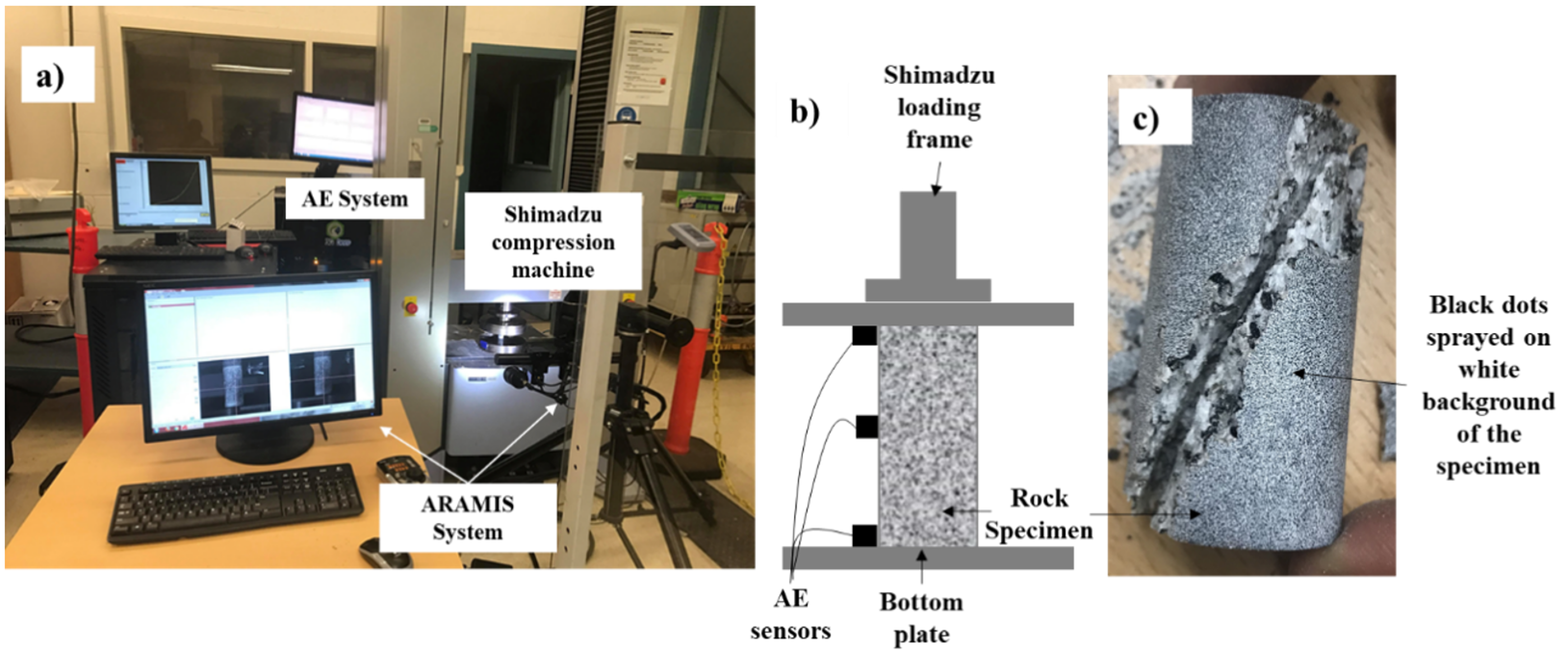
Uniaxial Compressive Strength (UCS) Testing

A series of uniaxial compressive strength tests were conducted on the cooled preheated specimens under uniaxial conditions, following ASTM standards, using a Shimadzu compression machine with the loading capacity of 300 kN available in the Deep Earth Energy Research Laboratory at Monash University. Loading was applied at a constant displacement rate of 0.1 mm/min. The applied vertical loads and the corresponding vertical displacements were monitored using a data acquisition system connected to the Shimadzu machine. In addition, the horizontal displacement of the specimen during loading was monitored through image analysis using the ARAMIS photogrammetry technique (3D camera technology), which uses two high-resolution cameras (5 megapixels 3.45 micron pitch) with 5 Hz to detect 3-D deformation of points at every 2 s (with 5 Hz frequency). For that purpose, isolated points were created on the cylindrical surface of the sample by spraying paint (Refer Figure 4).

2.3. Identification of Crack Initiation and Crack Damage Thresholds during Loading

According to Bieniawski [36], the fracturing process in brittle rocks occurs in several stages during loading. The initial stage is crack closure, which occurs in a rock material with existing natural cracks, and further loading causes crack initiation. Crack initiation is followed by stable and unstable crack propagation with subsequent loading. Identification of this threshold value for rocks is important in monitoring the loading and unloading processes in deep geological formations in geothermal reservoirs and nuclear waste disposal sites, which undergo loading and unloading during changing of fluid injection pressures and also seasonal changes of the water table. Different methods, including volumetric stiffness-strain curves, axial stiffness and stress-strain curves, and acoustic emission technology are used to identify the stress thresholds at these failure stages of brittle materials [31,36,37,38]. For this study, acoustic emission technology was incorporated.

Acoustic Emission (AE) Technique

For this study, the acoustic emission (AE) technique, which detects the AE counts and the absolute energy via transient elastic waves generated during loading, was incorporated to identify the crack propagation thresholds in the specimen by attaching three sensors to each specimen during UCS testing (the AE testing was carried out simultaneously with the uniaxial compression loading). During loading, AE signals originate due to the release of stored strain energy during the dislocation of grains, movements in grain boundaries, or during the initiation and propagation of micro-cracks [39]. The sensors were set to detect signals higher than 40 dB to avoid background noise, which were then amplified using amplifiers.

2.4. Identification of the Influence of Loading and Unloading after Crack Initiation and Crack Damage on Mechanical Alteration of Harcourt Granite

Hot rock formations in geothermal reservoirs and nuclear waste disposal sites undergo loading and unloading behaviour due to the change in fluid injection pressures and stress relaxation during fluid pumping and, integrated damage during multiple loading and unloading cycle results in reduction of mechanical properties of crystalline rocks. Therefore, this study aimed to evaluate the effect of loading and unloading at two stages, crack initiation stage and crack damage stage, on the permanent deformation of Harcourt granite rock specimens. Furthermore, the changes in mechanical properties such as Young’s modulus and Poisson’s ratio due to multiple loading and unloading steps were evaluated.

Loading and Unloading Testing under Uniaxial Compression

The average crack initiation and crack damage stress thresholds of Harcourt granite specimens subjected to heating followed by two cooling treatments (rapid and slow cooling) at different temperatures were identified during UCS testing through AE technique as discussed in Acoustic Emission (AE) Technique section. Then, loading and unloading tests were conducted for heat-treated specimens in two stages in which each specimen was initially loaded up to the crack initiation threshold and unloaded, and again loaded up to the crack damage stress threshold and unloaded and, followed by final loading up to ultimate failure. A Shimadzu compression test machine was used for testing with a loading rate of 0.1 mm/min and the vertical displacement and load were recorded using the data acquisition system.

2.5. Identification of Extent of Micro-Cracking during Thermal Treatments

It is important to investigate the extent of induced micro-cracking during heating followed by thermal treatments of crystalline rock formations and to identify the manner it influences the mechanical properties of rocks. Therefore, scanning electron microscopy (SEM) analysis was incorporated in this study to investigate the micro-cracks induced during heating followed by cooling treatments.

Scanning Electron Microscopy (SEM) Analysis

Thin slices subjected to heat treatment followed by two cooling mechanisms were used to observe the micro-structural changes in rock specimens subjected to heating followed by cooling treatments through the propagation of inter-granular and intra-granular cracks in the rock matrix. High-resolution images of the thin slices were captured using the JEOL JSM-7001F FEGSEM (Monash Center of Electron Microscope (MCEM), Melbourne, Australia) under a low vacuum mode. Micro-cracks inside grains and through grain boundaries were observed by SEM imaging, and the identification of mineral grains was done through energy-dispersive X-ray (EDX) analysis. Operating conditions of 15 kV with a working distance of 10 mm were used during the imaging process. To minimise the charging effect, a thin layer of carbon was coated on the surface of each slice and a magnification up to 1500 was selected since granite is medium-grained, and larger magnifications were not required to observe the micro-cracks.

3. Results and Discussion

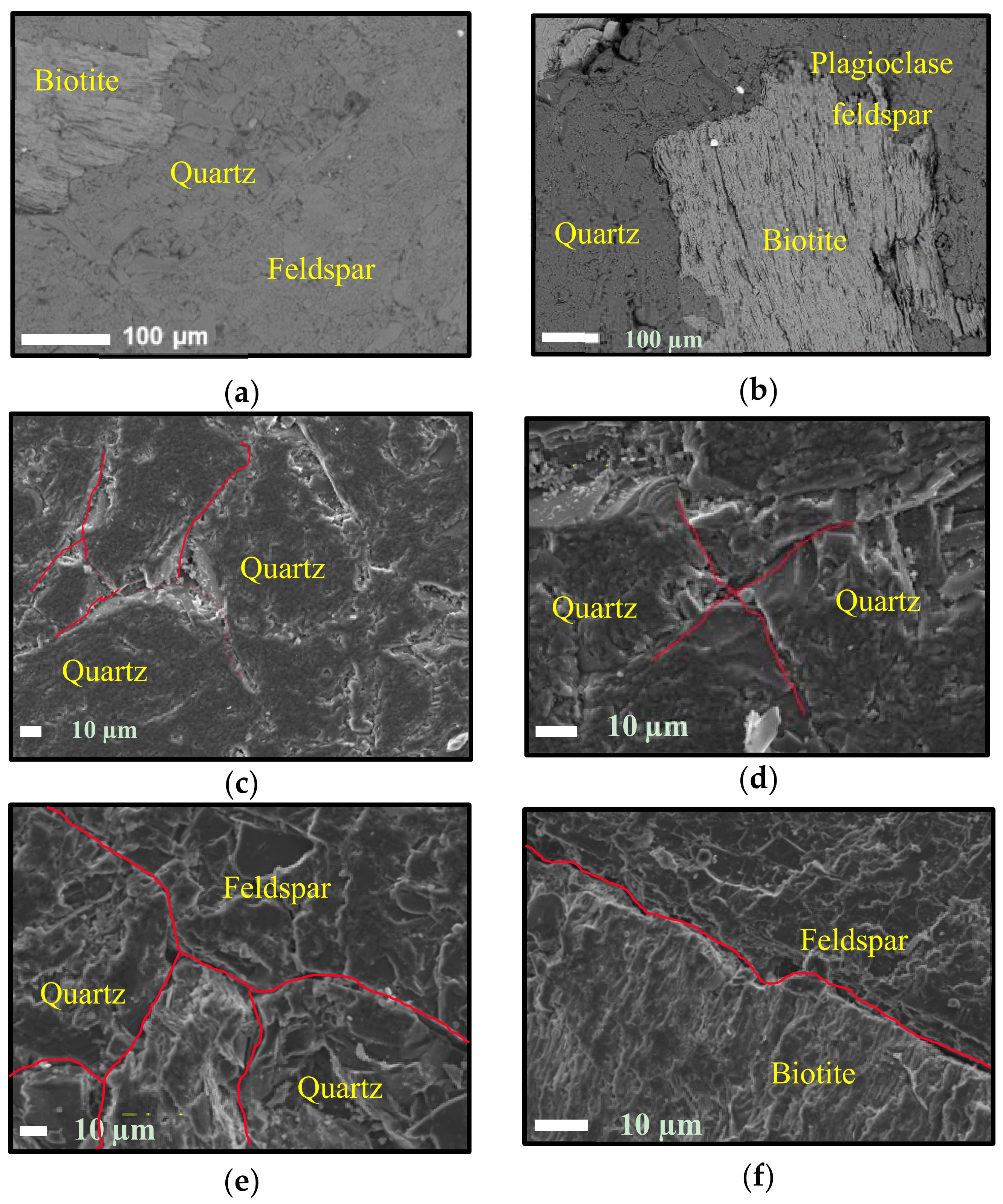
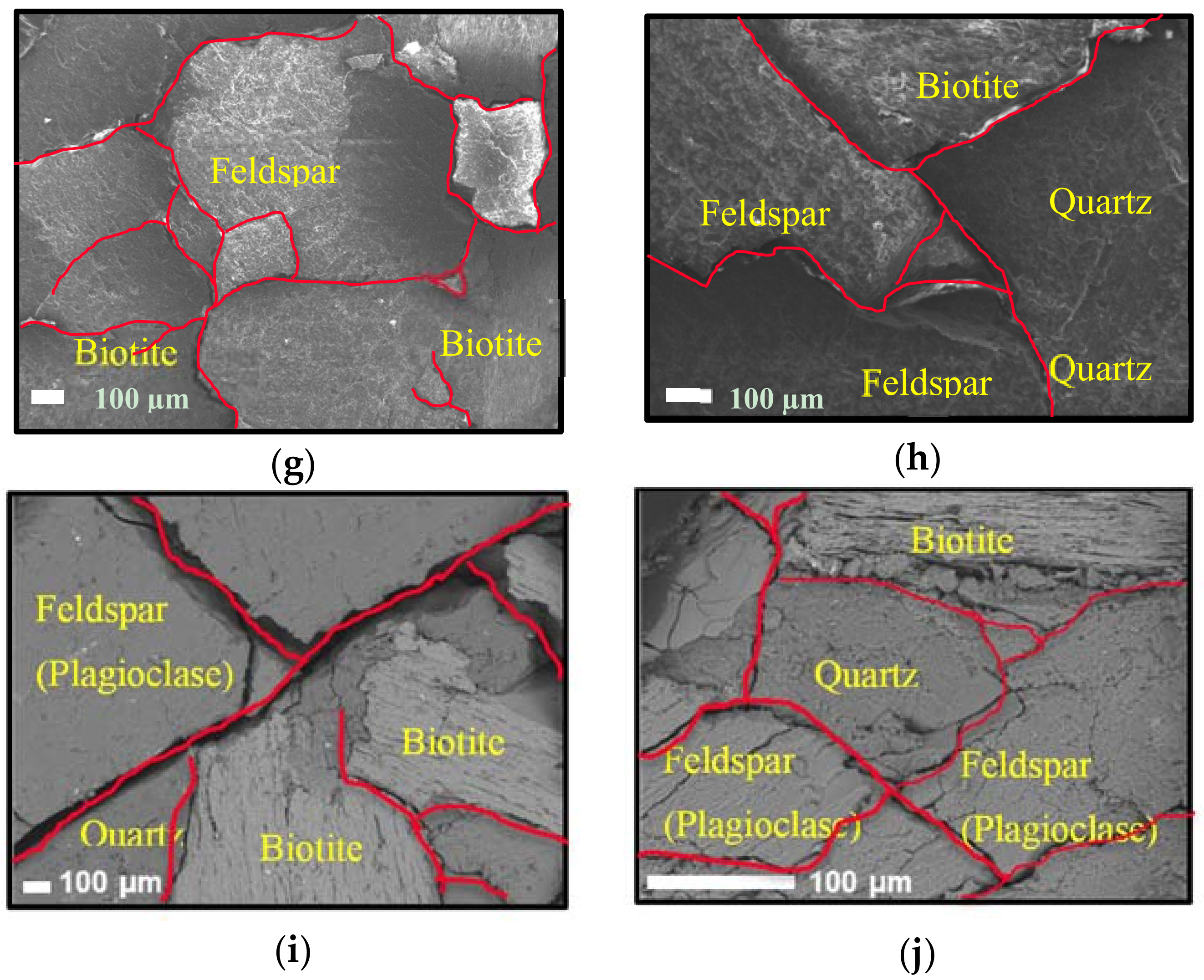
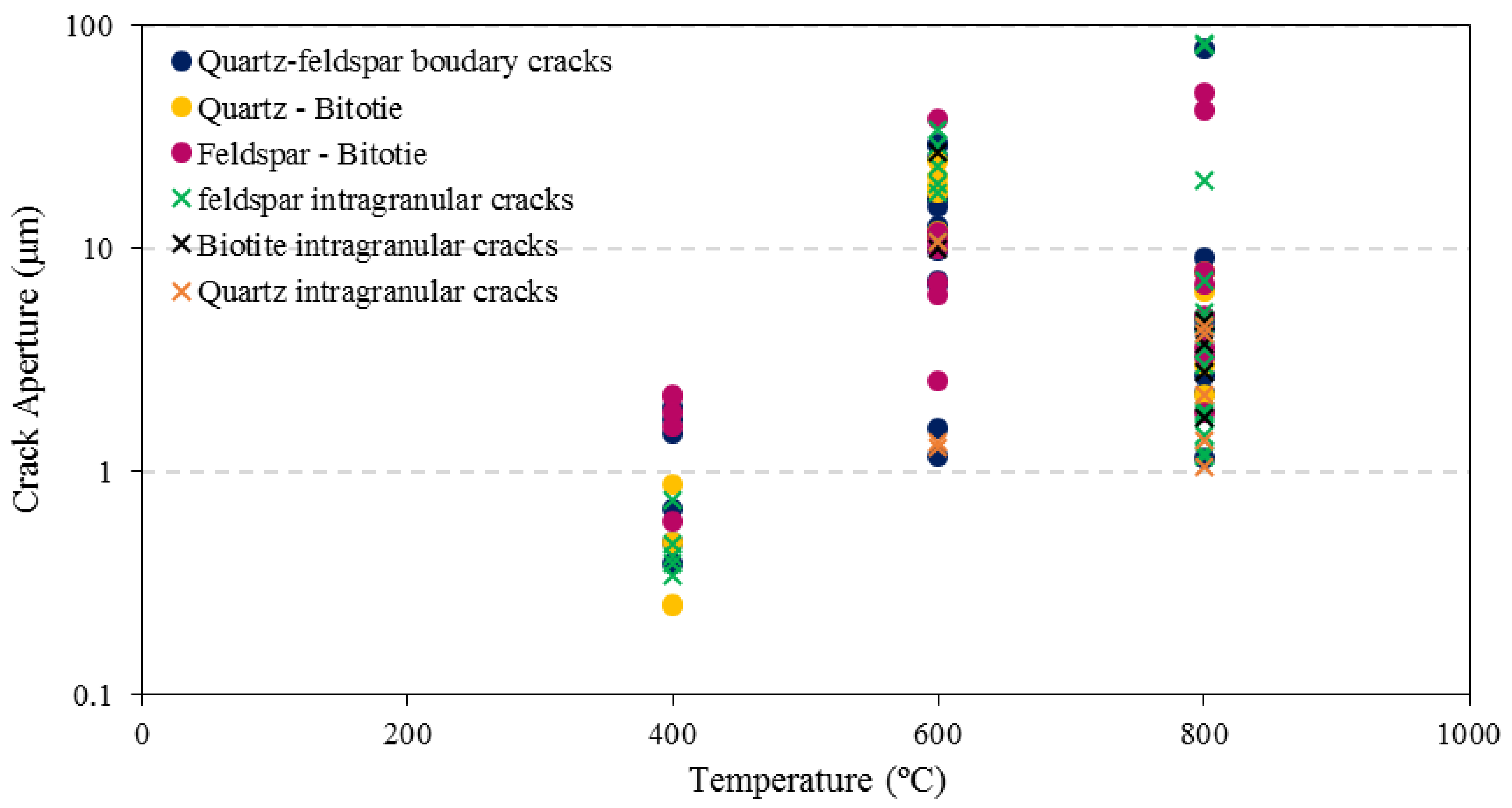
3.1. Identification of Thermally-Induced Micro-Cracking in Granite during Heating and Cooling

The micro-cracking in granite specimens is induced due to the anisotropy between the thermal expansion/contraction coefficients of different mineral types and the disorientation of grains during heating and cooling. Moreover, internal residual stresses are created as a result of the mis-match in strains among different minerals during both heating and cooling, which ultimately result in micro-cracking. Micro-cracking in thin slices subjected to heating followed by cooling treatments was observed from SEM imaging, and no propagation of thermal cracking was observed in slices pre-heated up to 200 °C followed by either slow or rapid cooling. In addition, no visible surface cracking was found in cylindrical specimens subjected to heat treatments up to 200 °C.
Interestingly, significant micro-cracking was observed in the thin slices which were heated beyond 200 °C followed by either rapid or slow cooling. Furthermore, tiny hair-like cracking was observed in the cylindrical specimens. SEM images of heat-treated specimens are shown in Figure 5. The propagation of both inter-granular and intra-granular micro-cracks among different mineral types during cooling was observed. The distribution of the apertures of micro-cracks (both inter-granular and intra-granular) are shown in Figure 6 for the temperature increase for thin slices subjected to rapid cooling. According to Figure 5 and Figure 6, the propagation of cracks through grain boundaries increases significantly with the increase of pre-heating temperature and the induced crack densities and apertures are higher under rapid cooling compared to slow cooling. The fracture densities (fracture opening area expressed as a percentage of total area within an image) of the thin slices subjected to heat treatment up to 400 °C, 600 °C and 800 °C temperatures followed by rapid cooling are 3.58%, 8.78% and 15.31%, respectively. Likewise, the fracture densities of the slices heat-treated up to 400 °C, 600 °C and 800 °C followed by slow cooling are 1.79%, 6.58% and 8.33%, respectively. It is also clear that higher fracture densities are induced during rapid cooling treatment in terms of both inter-granular and intra-granular cracks.
The granite specimens used for this study consisted of quartz, feldspar and biotite minerals. EDX analysis of these specimens showed that biotite grains are characterised by elongated shapes while quartz grains show sharply defined grain boundaries. At 400 °C, cracks along grain boundaries were observed and with further increase of temperature, the apertures of inter-granular cracks increased, and intra-granular cracks started to be induced. According to Gomez-Heras [40], this occurs first at triple junctions of grains since lower stress is needed to open up the boundaries due to high anisotropy. This is consistent with the present study (Figure 5e,g–i). At 600 °C, inter-granular cracks were observed in quartz and feldspar crystals while opening up of cleavages in biotite was also observed.
Deformation was observed in biotite crystals with the opening up of cleavages, but no intra-granular cracks were observed in biotite grains. Moreover, cracks along biotite boundaries were insignificant, while significant cracks were observed in adjacent grains. This is due to the fact that mica crystal boundaries concentrate induced stresses, while cracks propagate towards other surrounding grains. Ultimately, this results in significant cracks in surrounding grains (intra-granular and inter-granular cracks in quartz and feldspar grains). Greater deformations in mica boundaries indicate that higher stresses are confined in mica boundaries. Vázquez et al. [15] found that the stresses generated to create micro-cracking in mono-mineralic feldspar are much lower than the case when feldspar is in combination with quartz and biotite. Furthermore, the study showed that the presence of biotite influences the creation of intra-granular cracks in both quartz and feldspar crystals and dominates the system since its thermal expansion coefficient is much higher than that of both quartz and feldspar (refer to Table 2). The results of the present study confirm the above argument, and the numbers of cracks and crack apertures in feldspar crystals are greater than in the other two minerals.

3.2. Effect of Heating Followed by Cooling on Mechanical Properties of Granite

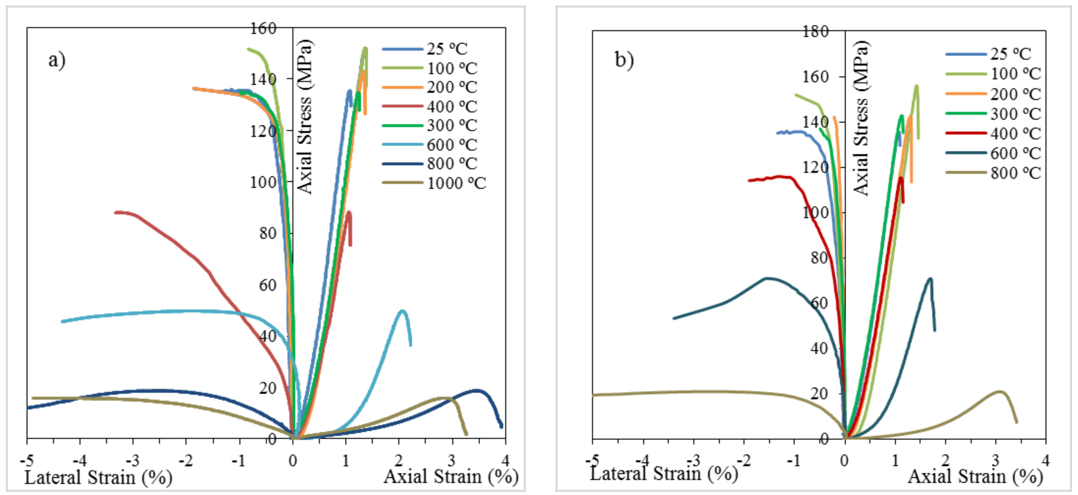
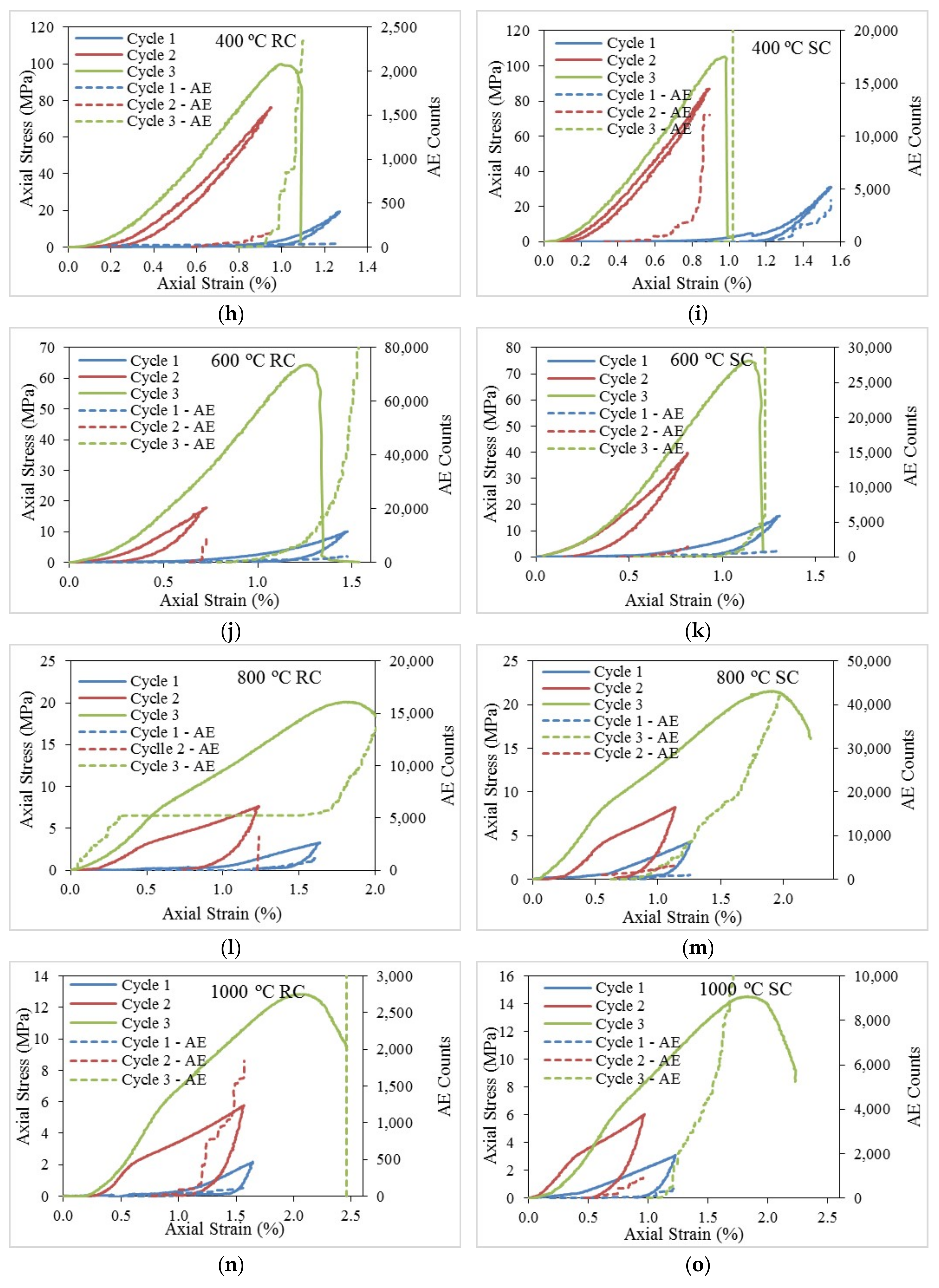
3.2.1. Stress-Strain Behaviour

The understanding of rock fracturing and failure mechanisms is important in the mining industry and other civil engineering applications. The stress-strain response of a rock mass until failure gives a fundamental understanding of the mechanical behaviour of rocks under compression loading. Figure 6 illustrates the stress-strain response of heat-treated samples followed by rapid cooling and slow cooling. Table 3 summarises the failure strength (UCS), Young’s modulus and Poisson’s ratio of each specimen with their average values for each condition tested.
According to Bieniawski [36], the initial non-linear behaviour of the stress-strain curve of brittle materials is due to the initial crack closure process in the rock matrix during loading. As Figure 7 indicates, this non-linear region is very small for specimens pre-heated up to 400 °C, and beyond this temperature, the non-linearity continues for more than half of the failure strain. This indicates that the initial crack density of specimens pre-heated beyond 400 °C is significant compared to specimens pre-heated to lower temperatures. In addition, over 400 °C, the rock characteristics deviate from brittle to quasi-brittle behaviour. The specimens with pre-heated temperatures up to 400 °C exhibit shear failure with diagonal cracks or cracks in a curved path along a direction parallel to the major principal axis, following a brittle failure mechanism. However, with the increase of pre-heating temperature over 400 °C, this behaviour deviates from brittle, more likely to ductile behaviour, with multiple failure plains distributed all over the sample. This may be due to the existing micro-cracks which rearrange and deform during loading, resulting in more complex behaviour at failure. Furthermore, the post-failure stress response during loading explains this deviation of brittle characteristics into the ductile behaviour of samples pre-heated over 400 °C, indicating a gradual reduction of stress associated with necking and deformation. In contrast, a sudden release of stress after failure was observed in rock specimens with pre-heating temperatures below 400 °C, which indicates a brittle failure mode (Figure 7). Moreover, the strain of failure increases with the increase of pre-heating temperature, further depicting the transfer of the brittleness of rock specimens to ductile behaviour.
The stress-strain response of rock specimens subjected to heating followed by rapid cooling and slow cooling treatments show certain dissimilarities explaining the effect of cooling on the mechanical properties of granite. According to Figure 7, the failure strains of rapidly cooled specimens are higher than those of slowly cooled rock specimens, and rapidly cooled samples show more non-linear characteristics during loading than slow cooled samples. In addition, rapidly cooled specimens show more ductile characteristics compared to slowly cooled specimens. This may be due to the greater number of thermally-induced micro-cracks in rapidly cooled samples than in slowly cooled samples, which contributes to more deformation before failure.

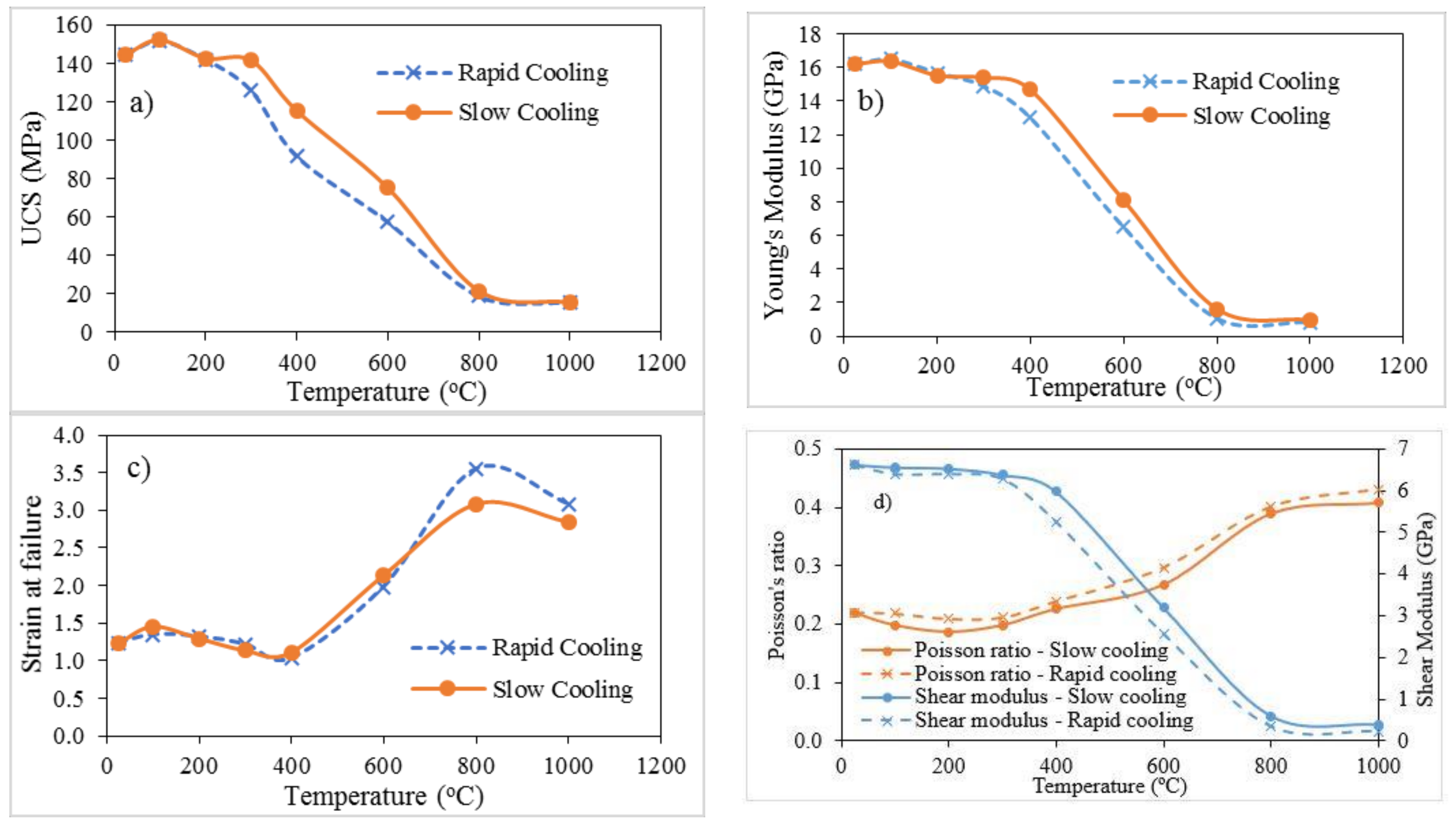
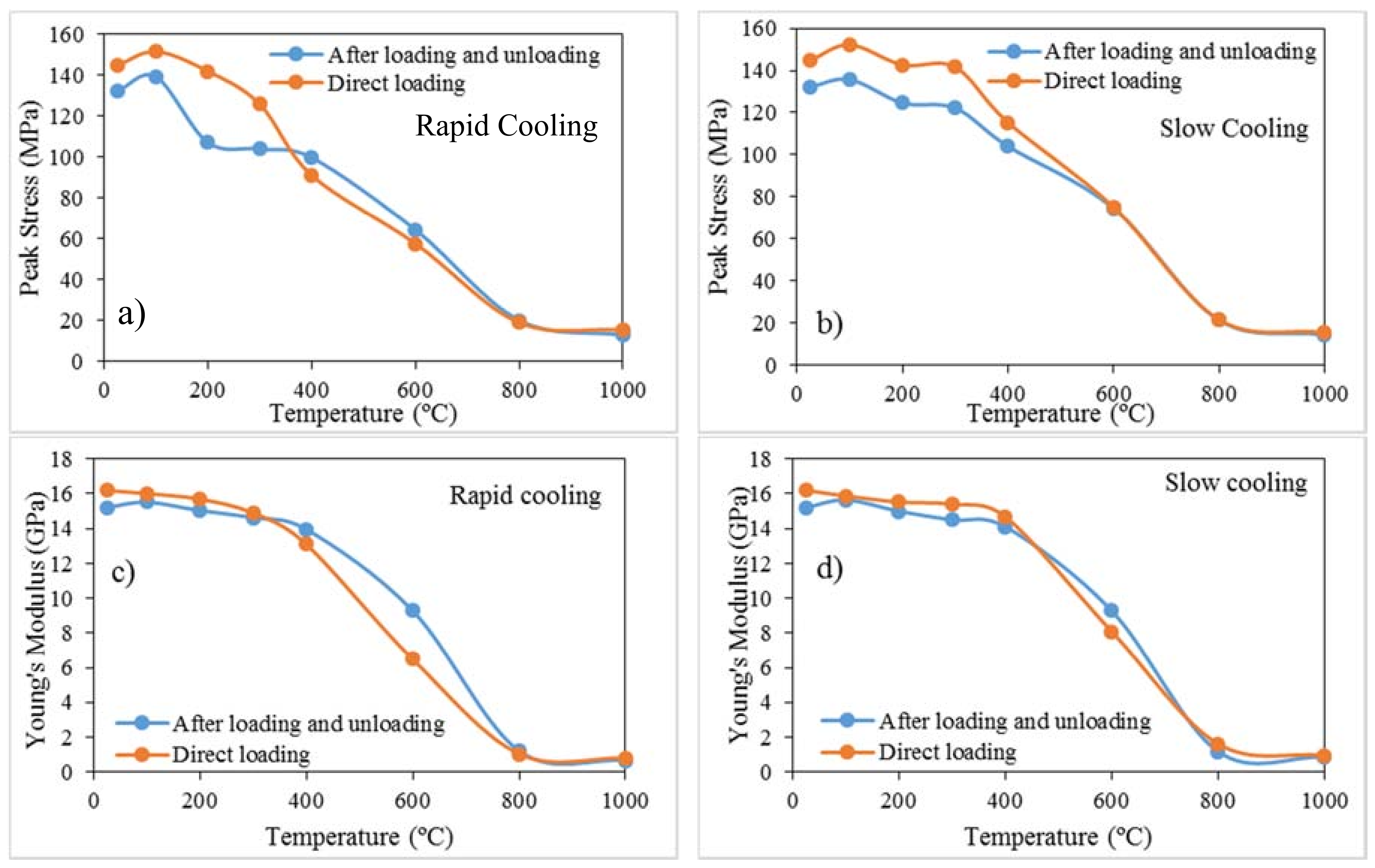
3.2.2. Uniaxial Compressive Strength (UCS)

Figure 8a shows the variation of the compressive strength values of Harcourt granite with increasing pre-heated temperatures under both slow cooling and rapid cooling treatments. Under both cooling treatments, an increasing trend of UCS values is observed with the increase of temperature up to 100 °C from room temperature (25 °C). The average increase of UCS value is 4.67% under the rapid cooling condition and 5.11% under the slow cooling condition. Many authors [41,42], have stated that the stresses induced during the thermal expansion and contraction processes involved with heating and cooling are confined up to a certain micro-cracking threshold, and this threshold lies around 130 °C for granite. Heating and cooling under this threshold temperature lead to gradual closure of existing cracks and pores due to the accompanying thermal expansion in rock mineral grains [31]. Therefore, this phenomenon influences increasing UCS values and Young’s modulus values at 100 °C (Figure 8) compared to the intact values at room temperature, which is clear from the present study. However, a decreasing trend in UCS values was observed with the increase of pre-heated temperature beyond 100 °C. The average rates of decrease in UCS values up to 400 °C were 39.54% and 24.21% under rapid and slow cooling, respectively, while from 400 to 1000 °C the UCS values exhibited faster reduction rates which were attributed to the thermal degradation of granite specimens. Thermal expansion and contraction during heating and cooling result in micro-cracking in granite specimens, inducing permanent matrix damage. Vázquez et al., [15] found that micro-cracking in granite creates visible damage when heating temperatures are above 400 °C and the SEM results of the present study further support the conclusion by Vázquez et al. [15]. Moreover, the temperature variation causes phase changes in individual minerals, such as the α to β transition of quartz at approximately 573 °C [43], which results in changes in the mechanical behaviour of quartz. In addition, the gradients of thermal expansion and the contraction coefficients of individual minerals in crystalline rocks like granite result in the opening of mineral boundaries and micro-cracking along grain boundaries, which jeopardises the strong contact among mineral grains. The micro-cracking may be due to both inter-granular and intra-granular cracks, and thin section analysis revealed that inter-granular cracking is the first to occur, and with increasing temperature, cracks appear to extend through the grains. This ultimately results in decreasing the strength characteristics of the rock specimens.
Importantly, the rate of decrease in UCS values is higher under rapid cooling than slow cooling for pre-heating temperatures over 300 °C, and up to 300 °C the changes in UCS values are insignificant. The strength reductions under rapid cooling treatment at pre-heating temperatures of 300 °C, 400 °C, 600 °C and 800 °C compared to the intact UCS value are 13.11%, 36.72%, 60.23% and 86.91%, respectively, whereas under slow cooling, these reduction rates are 2.24%, 20.36%, 48.05% and 85.11%, respectively. Rapid cooling induces sudden thermal shocks which create more micro-cracking in granite and this may be the reason for the significant strength reduction observed in rapidly cooled specimens. The thin section analysis also revealed that the crack densities of specimens subjected to rapid cooling are higher than those under slow cooling conditions. More thermal stresses induced during thermal shocking under rapid cooling create significant matrix damage to granite specimens, ultimately decreasing the strength properties at faster rates compared to slow cooling. According to the results, it is clear that the different cooling treatments have considerable effects on the strength properties of granite. As stated by Kumari et al. [31], rapid cooling decreases the UCS values for Strathbogie granite, even at temperatures below 300 °C, compared to slow cooling. Importantly, matrix damage during both heating and cooling treatments seems to accelerate with the increase of grain size in granite, since Strathbogie granite has larger grains (>3 mm) [32], whereas the grain size of Harcourt granite lies within the range of 0.3–1.5 mm. Small grains show a comparatively stable behaviour for thermal shocks compared to large size grains since the change in volume is small in smaller grains under thermal expansion and contraction. This phenomenon is the probable reason for not finding significant differences in UCS values for pre-heating temperatures up to 300 °C.

3.2.3. Elasticity Properties of Harcourt Granite

The elastic properties, including Young’s modulus, shear modulus, bulk modulus and Poisson’s ratio, of rock materials demonstrate the resistance of rock mass to deformation in terms of volume or shape. The Young’s modulus of Harcourt granite specimens was calculated considering the linear regions of the stress-strain curves. The Young’s modulus values over the increase of pre-heating temperature under both rapid and slow cooled conditions are illustrated in Figure 8b. According to the results, a slight increase of Young’s modulus was observed at 100 °C compared to room temperature under both cooling treatments (1.05% increase for slow cooling and 1.91% increase for rapid cooling). This further verifies that hardening of rock specimens occurs at this stage due to crack closure during thermal expansion. Moreover, the increase of Young’s modulus improves the rock’s compressive strength by bonding grains together, ultimately making a harder rock matrix.
With the increase of pre-heating temperature over 100 °C, Young’s modulus shows a decreasing trend similar to the trend observed in compressive strength. Furthermore, the rate of reduction of Young’s modulus under rapid cooling and slow cooling conditions are 19.63% and 9.38%, respectively up to the pre-heating temperature of 400 °C. Thereafter, a rapid decline in Young’s modulus was observed under both cooling treatments. Interestingly, the rate of reduction of Young’s modulus under rapid cooling is approximately twice that under slow cooling. This further confirms the occurrence of high thermal shocks during rapid cooling, which enhances micro-cracking in granite in terms of inter-granular or intra-granular cracks, ultimately resulting in reduced mechanical properties.
Strain values at failure are plotted in Figure 8c. As can be seen in the figure, failure strains at initial temperatures up to 400 °C are within the range of 1.1–1.3%, which shows brittle characteristics. However, with the increase of pre-heating temperatures beyond 400 °C, failure strains start to increase up to a range of 3.0–3.5%. This characterises the change of brittle behaviour to a quasi-brittle behaviour [44,45]. Importantly, the transition is achieved at a faster rate under rapid cooling than slow cooling. In addition, the shear modulus for each specimen was calculated using Young’s modulus values and Poisson’s ratios, and Figure 8d shows the variation of shear modulus. According to the results, considerably lower shear modulus can be seen in rapidly cooled specimens compared with slowly cooled specimens, and the divergence is negligible up to the pre-heated temperature of 400 °C. However, this difference is considerable for Harcourt granite specimens at pre-heated temperatures over 400 °C with the change of brittle behaviour more likely to ductile behaviour.
In conclusion, Harcourt granite specimens subjected to heating up to 400 °C followed by rapid cooling or slow cooling exhibit brittle characteristics during loading, and with the increase of pre-heating temperatures over 400 °C, rock specimens become less brittle, and show more ductile characteristics. Moreover, the rapid cooling process accelerates this phenomenon by inducing significant matrix damage.

3.2.4. Poisson’s Ratio

The Poisson’s ratio was calculated considering the linear region of the vertical and lateral stress-strain curves. The progression of Poisson’s ratio over the increase of pre-heating temperature for both rapid and slow cooling treatments is shown in Figure 8d. For initial pre-heating temperatures up to 400 °C, Poisson’s ratio values vary around 0.2, and over 400 °C, a substantial increase in Poisson’s ratio is observed under both rapid and slow cooling treatments. This observation further interprets the change of shear failure mechanism observed in brittle materials as buckling behaviour prevalent in ductile materials over pre-heating temperatures of 400 °C. However, the specimens which experienced slow cooling treatment showed lower Poisson’s ratio values than rapidly cooled specimens. As observed for the other elastic properties (e.g., Young’s modulus, shear modulus), the alteration of Poisson’s ratio also confirmed the transition of brittle characteristics with the increase of pre-heating temperature over 400 °C, and this occurs early in rapidly cooled specimens.

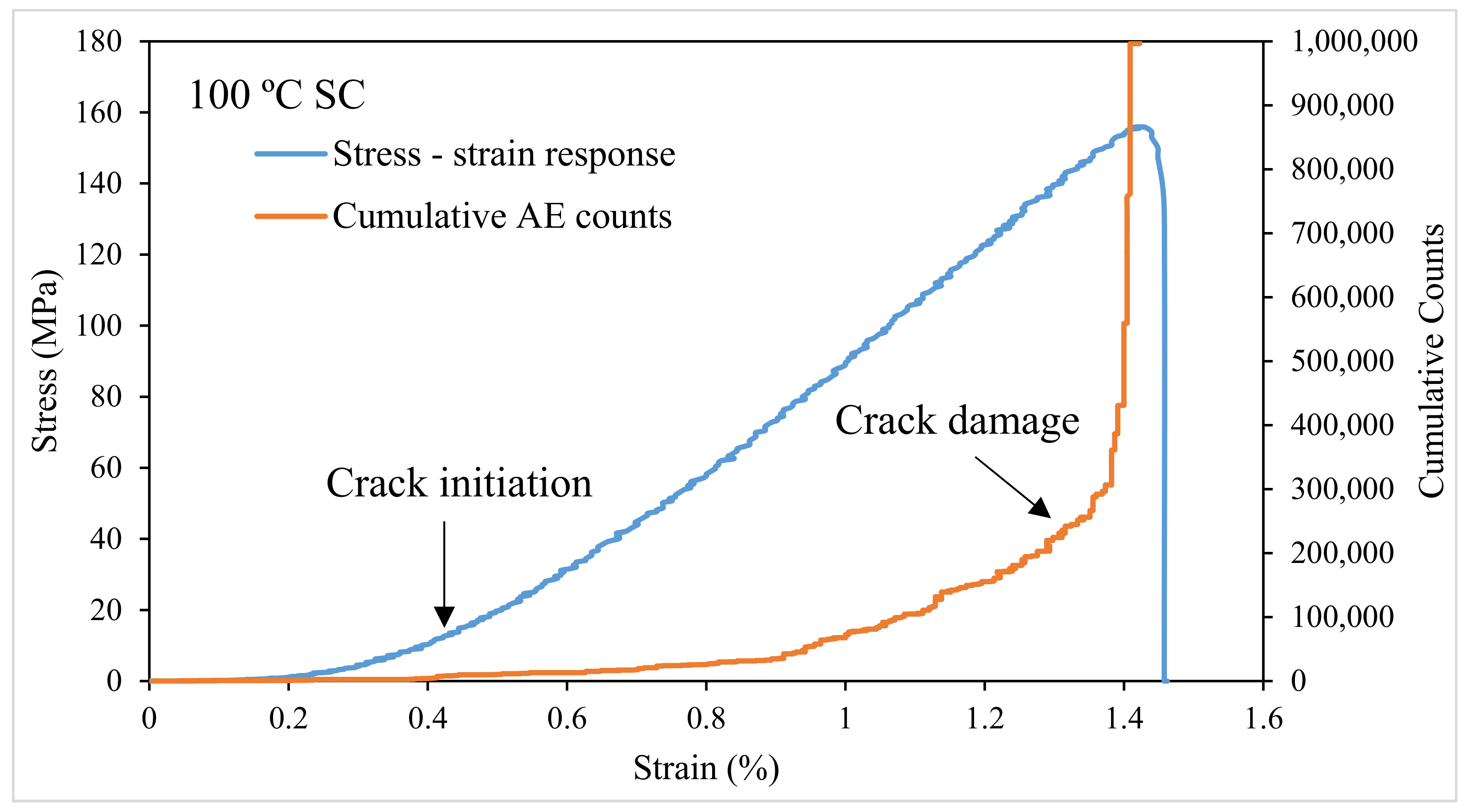
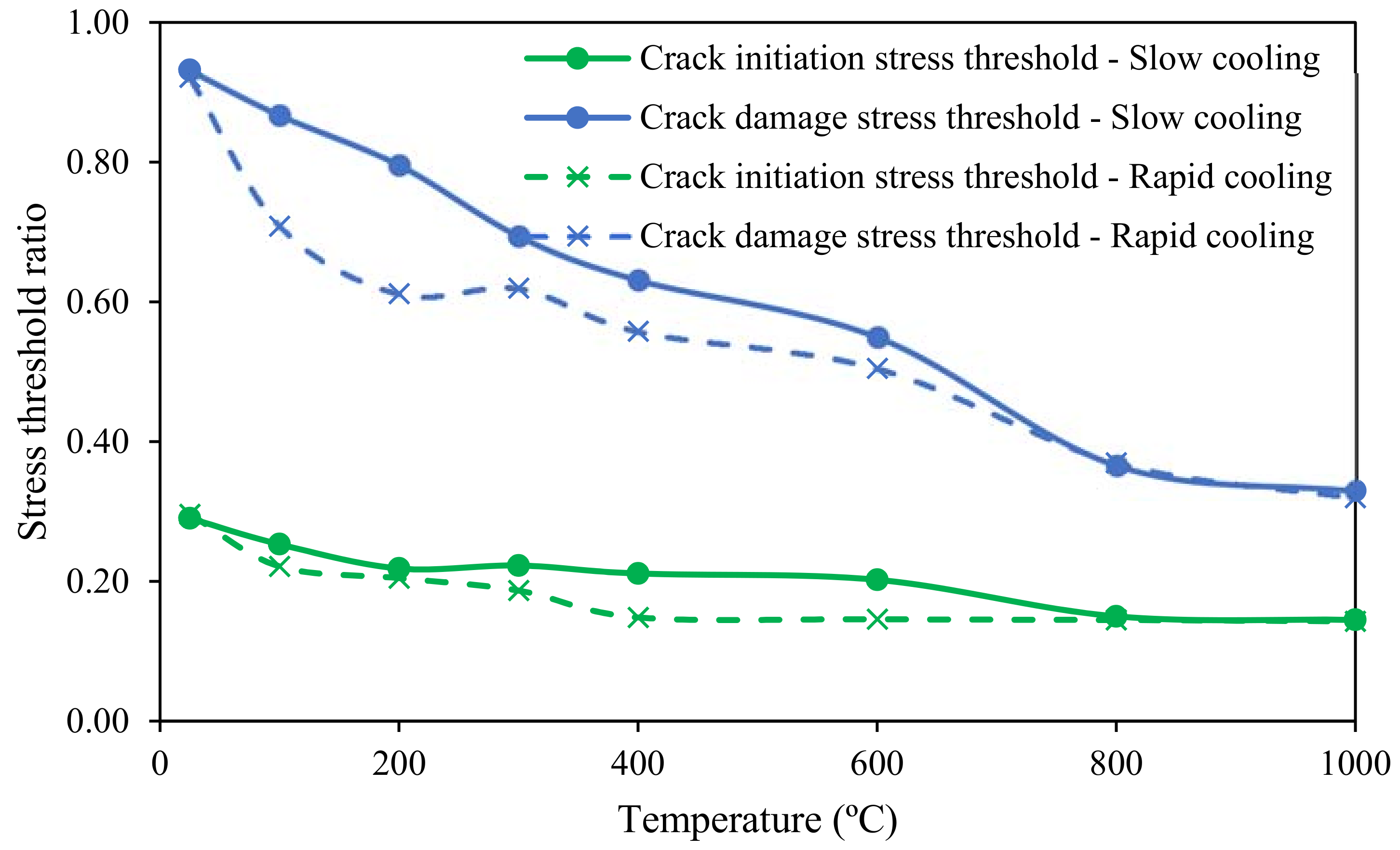
3.2.5. Crack Initiation and Crack Damage Thresholds

Failure of granite specimens under uniaxial loading occurs through a progressive process of micro-fracturing. Therefore, it is important to have an understanding of the stages of this micro-cracking process when studying the failure mechanisms in rock specimens. Bieniawski [36] explained the stages of micro-cracking during compression loading until failure as initial crack closure, linear elastic deformation, and fracture initiation followed by stable and unstable fracture propagation. Initially, the closure of pre-existing cracks inclined to the direction of loading occurs by re-arranging the grain boundaries. Thereafter, linear elastic deformation occurs with subsequent loading, which results in a constant modulus of elasticity. During this process, sliding of crack interfaces occurs, which results in the growth of stable brittle cracks in a direction parallel to the direction of large compressive stress (in the vertical direction) along the initial crack length [36,46]. With the increase of applied load, shear movement occurs along the fracture surfaces overcoming frictional resistance at the interlocking points. This results in the initiation of new fractures and the extension of existing cracks at the tips of initial cracks. Crack initiation is followed by crack propagation in a curved path along a direction parallel to the major principal axis. This mechanism of fracture propagation is influenced by the induced array of fractures, and it extends by connecting individual cracks or crack arrays.
For the present study, acoustic emission (AE) counts were plotted on the stress-strain curves for each sample to understand the crack initiation and crack damage thresholds. Figure 9 illustrates the plot of stress-strain responses with cumulative AE counts for a Harcourt granite specimen subjected to heating up to 100 °C followed by slow cooling. In the curve, crack initiation can be identified as the point where initial AE counts begin to rise, and AE counts emerge at increasing rates with crack propagation. Continuous propagation of cracks during subsequent loading creates crack damage in specimens. The identification of stresses at crack initiation and damage points was done for each rock specimen, and average values are given in Table 4 for each test condition. Furthermore, Figure 10 shows the variation of crack initiation thresholds and crack damage thresholds with increasing pre-heating temperatures. The crack initiation threshold expresses the ratio of the stress at crack initiation to the peak strength, and similarly, the crack damage threshold indicates the ratio of the stress at the crack damage to the peak strength. Under both rapid and slow cooling conditions, crack initiation occurs at around 20% of the peak strength and crack damage points show an interesting trend with temperature. Crack damage occurs at 92.2%, 85.7%, 78.8%, 68.8%, 49.4% and 36.1% of the failure strength for pre-heating temperatures of 25 °C, 100 °C, 200 °C, 300 °C, 400 °C and 600 °C, respectively under rapid cooling. For slow cooling, crack damage occurs at 84.1%, 79.2%, 69.8%, 63.2% and 56.5%, respectively for the same pre-heating temperatures. It is clear that crack damage occurs early with increased pre-heating temperatures under both rapid and slow cooling treatments. The micro-cracks induced in treated specimens by heating and cooling are connected and extended during loading, and ultimately result in early crack damage. This is enhanced by rapid cooling treatment. High thermal shocks under rapid cooling create more micro-cracks in Harcourt granite specimens.

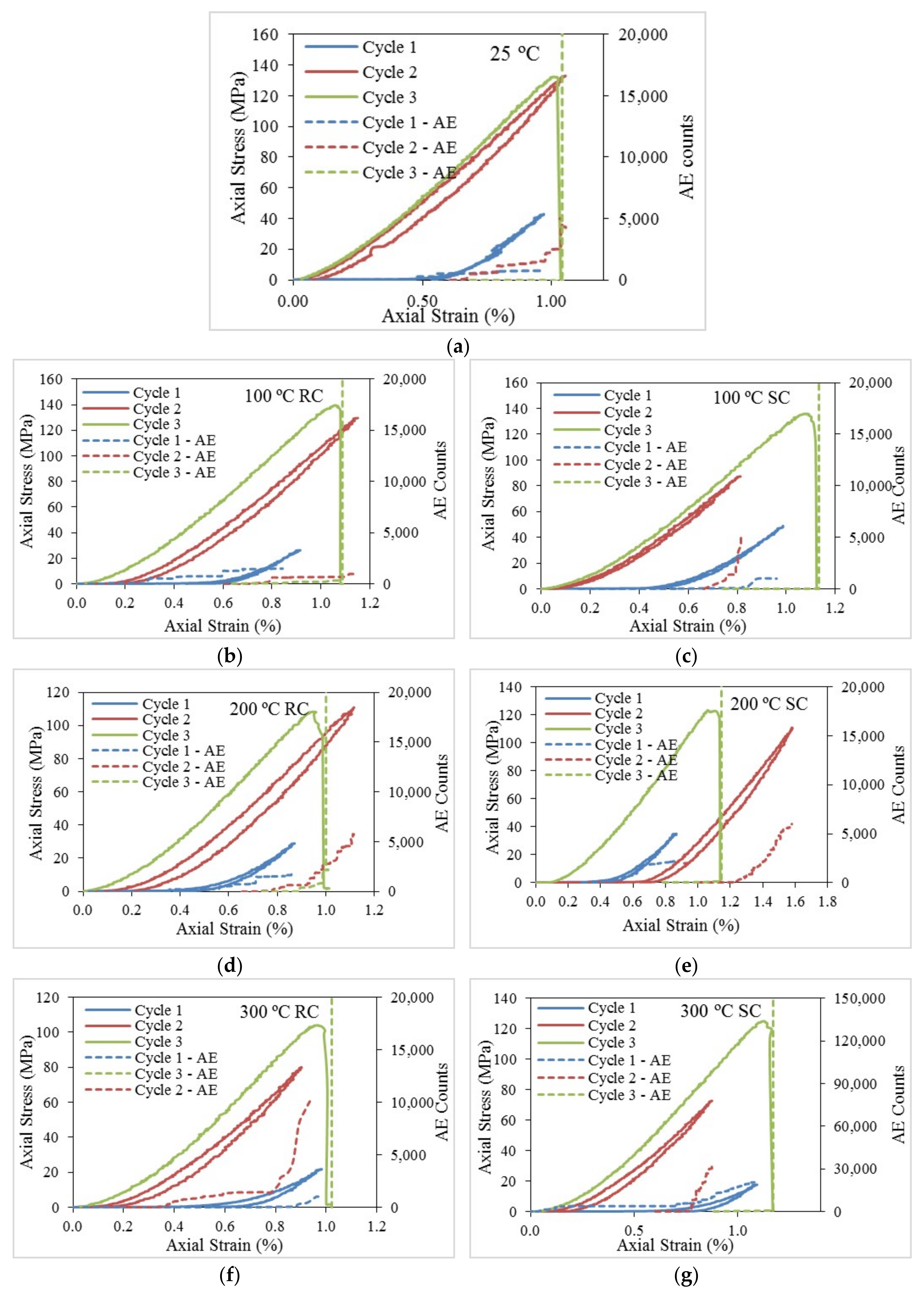
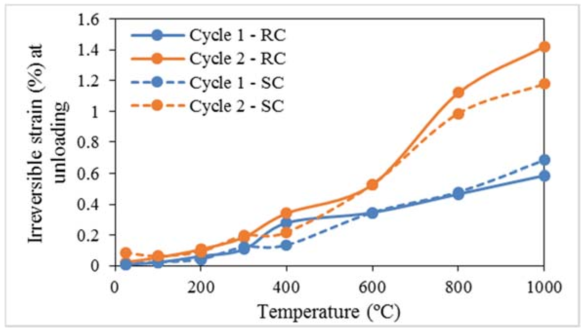
3.3. Effect of Loading and Unloading on Mechanical Properties of Harcourt Granite

The understanding of rock behaviour under changing loading conditions is important for safety assessments during underground geological applications, such as geothermal energy extraction and nuclear waste disposal. Loading followed by unloading prior to failure induce micro-fracturing in crystalline rocks, and ultimately change the mechanical properties by lowering the material stiffness [36]. Therefore, the changes in compressive strength values, Young’s modulus values and irreversible deformations under loading and unloading behaviour were evaluated using stress-strain curves. The graphs of stress-strain curves plotted with corresponding AE counts are illustrated in Figure 11 for each test specimen under each test condition. For UCS values, a reduction was observed for specimens subjected to loading and unloading behaviour up to a pre-heating temperature of 400 °C compared with the values of specimens subjected to monotonic loading, and thereafter a slight increase was observed for rapid cooling treatment (Figure 12a). For pre-heating temperatures of 25 °C, 100 °C, 200 °C, 300 °C and 400 °C, the percentages of reductions are within the 8–15% range for both rapid and slow cooling treatments. Under slow cooling, no change was observed for pre-heating temperatures over 400 °C (Figure 12b). Moreover, the Young’s modulus was calculated for each specimen under each test condition and compared with the values obtained during monotonic loading (Figure 12c,d). Similar to the trend in compressive strength, Young’s modulus exhibits a reduction under temperatures up to 400 °C and, thereafter, an increase under rapid cooling, but under slow cooling, this increment is insignificant.
Reductions of UCS values and Young’s modulus values under initial pre-heating temperatures during loading and unloading occur due to the integrated stress-induced fracture damage in brittle materials in crystalline rock formations. When the applied load during the loading stage reaches the crack initiation threshold, the progressive development in cracks induces the extension of the micro-fracture network. However, the induced cracks do not seem to recover during the unloading stage and create irreversible deformations in the rock matrix. Moreover, multiple stages of loading and unloading prior to failure make the rock matrix weaker in strength properties through the continuous accumulation of fracture damage [24,47,48]. The irreversible strains resulting during loading cycle 1 and loading cycle 2 are plotted in Figure 13 for both cooling treatments. Loading up to crack initiation and unloading leaves small irreversible strains, initiating new cracks during the first cycle of loading. During the second cycle of loading, these initiated cracks reactivate and propagate until unloading. The coalescence of small individual cracks into larger cracks through bridging happens during loading cycle 2, and it increases the crack density and crack size, reducing material stiffness. Figure 14 illustrates the mechanism of coalescence which prevails during loading and unloading, where plastic strains are induced due to the collapse and weakening of the bridging material [49]. When this process continues with progressive accumulation in plastic strains during subsequent loading and unloading cycles, a decline in strength properties occurs in brittle materials.
However, the above behaviour is insignificant with the increase of pre-heating temperatures over 600° under both rapid and slow cooling treatments, as shown in Figure 13 and Figure 14. Due to the initial thermal damage in rock specimens during heating followed by cooling treatments for pre-heating temperatures above 400 °C, a small load increment is sufficient to create coalescence and bridging of materials, which can be achieved even within the first cycle of loading. The observed higher plastic strains even during first cycle of loading further explain this. However, rearrangement of already formed cracks can happen during loading and unloading, which does not significantly affect the strength properties of rock specimens.
According to the results, the loading and unloading processes that can prevail in underground geological formations up to 400 °C significantly affect the reduction of strength properties such as compressive strength and Young’s modulus. With the increase of temperature over 400 °C, a change of brittle characteristics, most likely to ductile behaviour, makes this loading and unloading behaviour insignificant in terms of strength properties. Furthermore, the different mechanisms of cooling do not seem to influence the behaviour of strength properties, and specimens under both treatments show a similar tendency of change.

4. Conclusions

In this study, different experimental approaches were carried out to evaluate the thermo-mechanical behaviour of Harcourt granite subjected to extreme heating followed by slow cooling and rapid cooling treatments. According to the results, the following conclusions can be drawn:
  • The stress-strain response under uniaxial loading reveals that Harcourt granite deviates from brittle behaviour to a quasi-brittle behaviour with the increase of pre-heating temperature over 400 °C, and this seems significant under rapid cooling treatment due to the larger thermal shocks induced by high cooling rates. An increase in elastic properties (uniaxial compressive strength and Young’s modulus) resulted with pre-heating up to a threshold temperature (for Harcourt granite, the threshold temperature lies at around 100 °C) for both cooling treatments, due to the closure of existing fractures through thermal expansion processes. Beyond that threshold temperature, a significant decline in strength properties occured due to the rock matrix damage created by thermally-induced micro-cracking. Furthermore, the strength reduction was greater under rapid cooling, revealing that the cooling effect is crucial for the elastic properties of Harcourt granite, especially over 300 °C. Interestingly, the results revealed that the increasing temperature causes the brittle-quasi brittle transition at 600 °C.
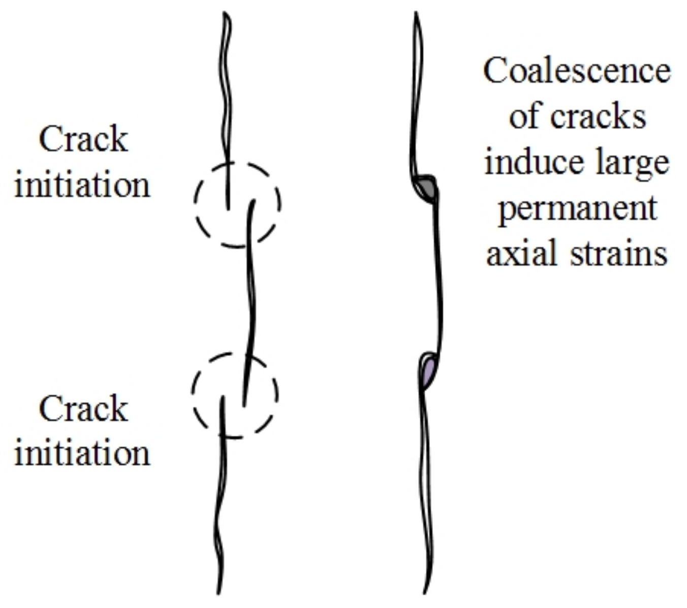
  • AE results showed that the crack initiation occurs at around 20% of the peak compressive strength of the specimens, irrespective of the pre-heating temperatures and cooling treatments, and the crack damage thresholds seem to vary with the pre-heating temperature. Early crack damage occurred with the increase of pre-heating temperature and was increased for specimens subjected to rapid cooling. Loading and unloading before failure were found to be significant for the deterioration of mechanical properties of Harcourt granite, and for pre-heating temperatures up to 400 °C, a reduction in strength properties was found in specimens subjected to loading and unloading cycles. This is probably due to rock matrix damage through the coalescence of micro-cracks. However, over 400 °C this effect seems to reduce.
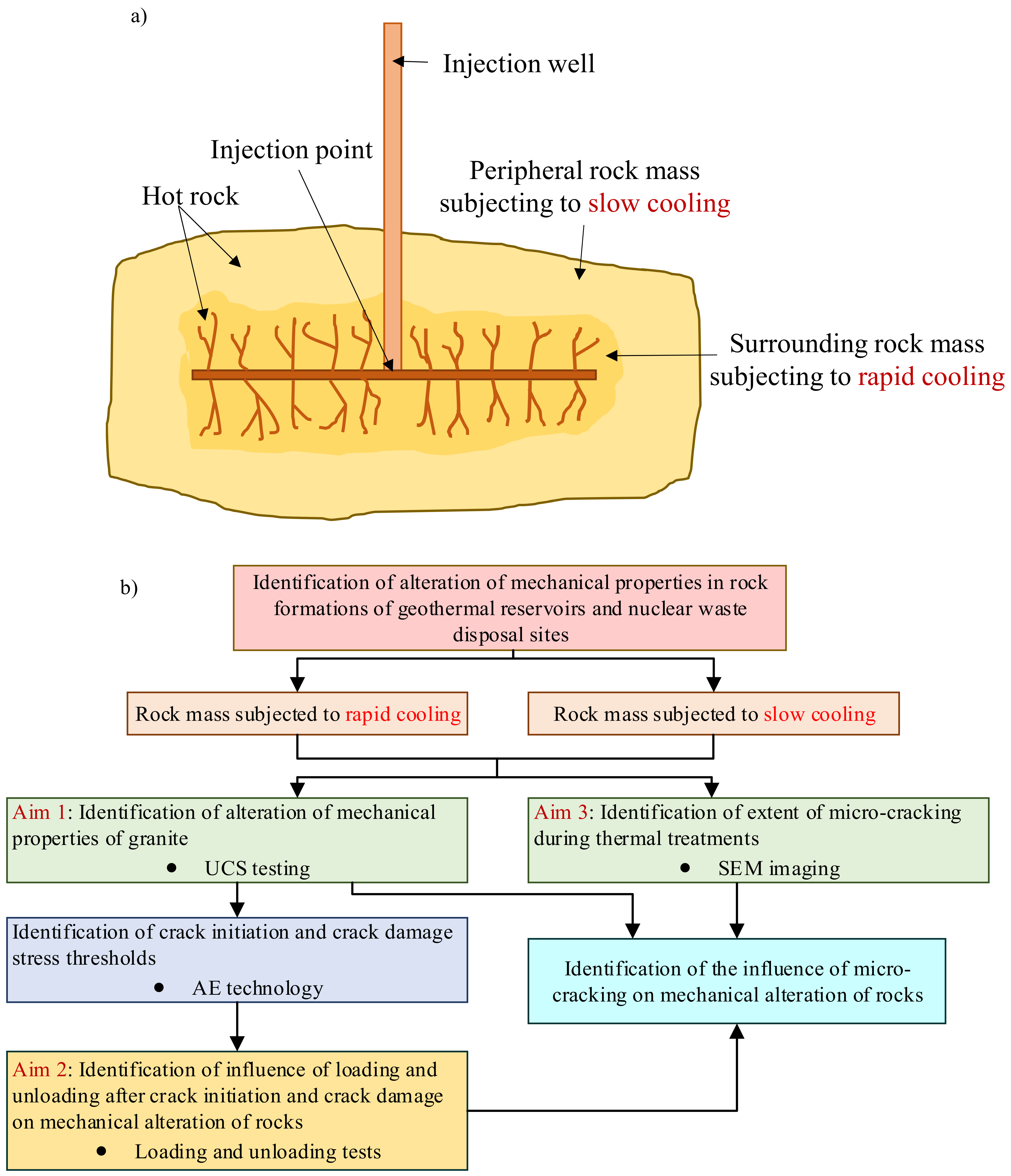
  • According to this study, greater thermal shocks created during rapid cooling in hot dry rocks near the injection point of geothermal reservoirs and nuclear waste disposal sites seem to cause significant matrix damage to the reservoir rock through thermally-induced micro-cracking and this effect increases with the increase of temperature. In addition, micro-cracking in adjacent regions close to the injection point which undergo slow cooling is not as critical as that in rapidly cooled areas. However, the effect of slow cooling areas also needs to be considered when planning and designing deep reservoirs for geothermal energy and nuclear waste-disposal sites. Therefore, the results of this study are important for accurately modelling the behaviour of underground geological formations; geothermal reservoirs and nuclear waste disposal sites.

Author Contributions

The experimental work, data analysis and initial draft of the paper was done by Badulla Liyanage Avanthi Isaka. The drafted manuscript was corrected and reviewed by Tharaka Dilanka Rathnaweera, Samintha Anne Perera. Dornadula Chandrasekharam and Wanniarachchige Gnamani Pabasara Kumari contributed in discussion of results. The concept was conceived by Ranjith Pathegama Gamage and also the final review of the paper.

Conflicts of Interest

The authors declare no conflicts of interest.

References

  1. International Energy Agency (IEA). World Energy Balances: Overview (2017 Edition); International Energy Agency (IEA): Paris, France, 2017; Available online: https://www.iea.org/publications/freepublications/publication/world-energy-balances---2017-edition---overview.html (accessed on 1 December 2017).
  2. Teke, O.; Yaşar, E. Geothermal energy and integrated resource management in Turkey. Geomech. Geophys. Geo-Energy Geo-Resour. 2018, 4, 1–10. [Google Scholar] [CrossRef]
  3. Budd, A.R.; Gerner, E.J. Externalities are the dominant cause of faltering in Australian geothermal energy development. In Proceedings of the World Geothermal Congress, Melbourne, Australia, 19–25 April 2015; pp. 1–13. [Google Scholar]
  4. Breede, K.; Dzebisashvili, K.; Falcone, G. Overcoming challenges in the classification of deep geothermal potential. Geotherm. Energy Sci. 2015, 3, 19–39. [Google Scholar] [CrossRef]
  5. Breede, K.; Dzebisashvili, K.; Liu, X.; Falcone, G. A systematic review of enhanced (or engineered) geothermal systems: Past, present and future. Geotherm. Energy 2013, 1, 1–27. [Google Scholar] [CrossRef]
  6. Budd, A. What’s Happened to Geothermal? Simple in Concept- Complex in Application; Geoscience Australia: Symonston, Australia, 2013; pp. 1–30. [Google Scholar]
  7. Feng, Z.; Zhao, Y.; Zhou, A.; Zhang, N. Development program of hot dry rock geothermal resource in the Yangbajing Basin of China. Renew. Energy 2012, 39, 490–495. [Google Scholar] [CrossRef]
  8. Zhao, Y.; Feng, Z.; Feng, Z.; Yang, D.; Liang, W. THM (Thermo-hydro-mechanical) coupled mathematical model of fractured media and numerical simulation of a 3D enhanced geothermal system at 573 K and buried depth 6000–7000 M. Energy 2015, 82, 193–205. [Google Scholar] [CrossRef]
  9. Brook, B.W.; Alonso, A.; Meneley, D.A.; Misak, J.; Blees, T.; van Erp, J.B. Why nuclear energy is sustainable and has to be part of the energy mix. Sustain. Mater. Technol. 2014, 1, 8–16. [Google Scholar] [CrossRef]
  10. Fairhurst, C. Nuclear waste disposal and rock mechanics: Contributions of the Underground Research Laboratory (URL), Pinawa, Manitoba, Canada. Int. J. Rock Mech. Min. Sci. 2004, 41, 1221–1227. [Google Scholar] [CrossRef]
  11. Gens, A.; Guimaraes, L.D.N.; Garcia-Molina, A.; Alonso, E.E. Factors controlling rock–clay buffer interaction in a radioactive waste repository. Eng. Geol. 2002, 64, 297–308. [Google Scholar] [CrossRef]
  12. Heuze, F.E. Geotechnical Modeling of High-Level Nuclear Waste Disposal by Rock Melting; Lawrence Livermore National Lab.: Livermore, CA, USA, 1981. [Google Scholar]
  13. Logan, S.E. Deep self-burial of radioactive wastes by rock-melting capsules. Nucl. Technol. 1974, 21, 111–124. [Google Scholar] [CrossRef]
  14. David, C.; Menéndez, B.; Darot, M. Influence of stress-induced and thermal cracking on physical properties and microstructure of La Peyratte granite. Int. J. Rock Mech. Min. Sci. 1999, 36, 433–448. [Google Scholar] [CrossRef]
  15. Vázquez, P.; Shushakova, V.; Gómez-Heras, M. Influence of mineralogy on granite decay induced by temperature increase: Experimental observations and stress simulation. Eng. Geol. 2015, 189, 58–67. [Google Scholar] [CrossRef]
  16. Gomez-Heras, M.; Gomez-Villalba, L.S.; Fort, R. Cambios de Fase en Litoarenitas Calcáreas con la Temperatura: Implicaciones para el Deterioro Causado por Incendios. Macla Rev. Soc. Esp. Mineral. 2010, 13, 101–102. [Google Scholar]
  17. Spearing, D.R.; Farnan, I.; Stebbins, J.F. Dynamics of the α-β phase transitions in quartz and cristobalite as observed by in-situ high temperature 29 Si and 17 O NMR. Phys. Chem. Miner. 1992, 19, 307–321. [Google Scholar] [CrossRef]
  18. Géraud, Y.; Mazerolle, F.; Raynaud, S. Comparison between connected and overall porosity of thermally stressed granites. J. Struct. Geol. 1992, 14, 981–990. [Google Scholar] [CrossRef]
  19. Lee, S.; Ghassemi, A. Thermo-poroelastic finite element analysis of rock deformation and damage. In Proceedings of the 43rd US Rock Mechanics Symposium & 4th US-Canada Rock Mechanics Symposium, Asheville, NC, USA, 28 June–1 July 2009. [Google Scholar]
  20. Chen, S.; Yang, C.; Wang, G. Evolution of Thermal Damage and Permeability of Beishan Granite. Appl. Therm. Eng. 2017, 110, 1533–1542. [Google Scholar] [CrossRef]
  21. Peng, J.; Rong, G.; Cai, M.; Yao, M.; Wang, G. Physical and Mechanical Behaviors of a Thermal-Damaged Coarse Marble under Uniaxial Compression. Eng. Geol. 2016, 200, 88–93. [Google Scholar] [CrossRef]
  22. Su, H.; Jing, H.; Yin, Q.; Yu, L.; Wang, Y.; Wu, X. Strength and Deformation Behaviors of Veined Marble Specimens after Vacuum Heat Treatment under Conventional Triaxial Compression. Acta Mech. Sin. 2017, 33, 886–898. [Google Scholar] [CrossRef]
  23. Tian, H.; Mei, G.; Jiang, G.; Qin, Y. High-Temperature Influence on Mechanical Properties of Diorite. Rock Mech. Rock Eng. 2017, 50, 1661–1666. [Google Scholar] [CrossRef]
  24. Heap, M.J.; Faulkner, D.R. Quantifying the evolution of static elastic properties as crystalline rock approaches failure. Int. J. Rock Mech. Min. Sci. 2008, 45, 564–573. [Google Scholar] [CrossRef]
  25. Yang, S.Q.; Ranjith, P.G.; Jing, H.W.; Tian, W.L.; Ju, Y. An experimental investigation on thermal damage and failure mechanical behavior of granite after exposure to different high temperature treatments. Geothermics 2017, 65, 180–197. [Google Scholar] [CrossRef]
  26. Kumari, W.G.P.; Ranjith, P.G.; Perera, M.S.A.; Shao, S.; Chen, B.K.; Lashin, A.; Al Arifi, N.; Rathnaweera, T.D. Mechanical behaviour of Australian Strathbogie granite under in-situ stress and temperature conditions: An application to geothermal energy extraction. Geothermics 2017, 65, 44–59. [Google Scholar] [CrossRef]
  27. Dwivedi, R.D.; Goel, R.K.; Prasad, V.V.R.; Sinha, A. Thermo-mechanical properties of Indian and other granites. Int. J. Rock Mech. Min. Sci. 2008, 45, 303–315. [Google Scholar] [CrossRef]
  28. Zhao, Y.S.; Wan, Z.J.; Feng, Z.J.; Xu, Z.H.; Liang, W.G. Evolution of mechanical properties of granite at high temperature and high pressure. Geomech. Geophys. Geo-Energy Geo-Resour. 2017, 3, 199–210. [Google Scholar] [CrossRef]
  29. Fan, L.F.; Wu, Z.J.; Wan, Z.; Gao, J.W. Experimental investigation of thermal effects on dynamic behavior of granite. Appl. Therm. Eng. 2017, 125, 94–103. [Google Scholar] [CrossRef]
  30. Shao, S.; Wasantha, P.L.P.; Ranjith, P.G.; Chen, B.K. Effect of cooling rate on the mechanical behavior of heated Strathbogie granite with different grain sizes. Int. J. Rock Mech. Min. Sci. 2014, 70, 381–387. [Google Scholar] [CrossRef]
  31. Kumari, W.G.P.; Ranjith, P.G.; Perera, M.S.A.; Chen, B.K.; Abdulagatov, I.M. Temperature-dependent mechanical behaviour of Australian Strathbogie granite with different cooling treatments. Eng. Geol. 2017, 229, 31–44. [Google Scholar] [CrossRef]
  32. CCM- Mount Alexander. 2017. Available online: http://cartography.id.au/mt_alexander/mt_alexander.html (accessed on 14 September 2017).
  33. Yu, Q.; Zhu, W.; Ranjith, P.G.; Shao, S. Numerical simulation and interpretation of the grain size effect on rock strength. Geomech. Geophys. Geo-Energy Geo-Resour. 2018, 4, 157–173. [Google Scholar] [CrossRef]
  34. Brace, W.F. Dependence of fracture strength of rocks on grain size. In Proceedings of the 4th US Symposium on Rock Mechanics (USRMS), University Park, PA, USA, 30 March–1 April 1961. [Google Scholar]
  35. Chaki, S.; Takarli, M.; Agbodjan, W. Influence of thermal damage on physical properties of a granite rock: Porosity, permeability and ultrasonic wave evolutions. Constr. Build. Mater. 2008, 22, 1456–1461. [Google Scholar] [CrossRef]
  36. Bieniawski, Z.T. Mechanism of brittle fracture of rock: Part I—Theory of the fracture process. Int. J. Rock Mech. Min. Sci. Geomech. Abstr. 1967, 4, 395–406. [Google Scholar] [CrossRef]
  37. Rathnaweera, T.; Ranjith, P.; Perera, M. Salinity-dependent strength and stress–strain characteristics of reservoir rocks in deep saline aquifers: An experimental study. Fuel 2014, 122, 1–11. [Google Scholar] [CrossRef]
  38. Ranjith, P.G.; Jasinge, D.; Song, J.Y.; Choi, S.K. A study of the effect of displacement rate and moisture content on the mechanical properties of concrete: Use of acoustic emission. Mech. Mater. 2008, 40, 453–469. [Google Scholar] [CrossRef]
  39. Eberhardt, E.; Stead, D.; Stimpson, B.; Read, R.S. Identifying crack initiation and propagation thresholds in brittle rock. Can. Geotech. J. 1998, 35, 222–233. [Google Scholar] [CrossRef]
  40. Gomez-Heras, M.; Hajpál, M.; Álvarez de Buergo, M.; Török, A.; Fort, R.; Varas, M.J. Evolution of porosity in Hungarian building stones after simulated burning. In Proceedings of the International Conference on Heritage Weathering and Conservation (HWC-2006), Madrid, Spain, 21–24 June 2006; pp. 513–519. [Google Scholar]
  41. De Argandoña, V.R.; Calleja, L.; Montoto, M. Determinación experimental del umbral de microfisuración térmica de la roca matriz o intact rock. Trab. Geol. 1985, 15, 299–307. [Google Scholar]
  42. Ruiz de Argandoña, V.G.; Calleja, L.; Suarez del Rio, L.M.; Montoto, M. Emision acustica/actividad microsismica generada bajo ciclos termicos en una roca granitica. Bol. Geol. Y Min. 1986, 97, 96–102. [Google Scholar]
  43. Somerton, W.H. Thermal Properties and Temperature-Related Behavior of Rock/Fluid Systems; Elsevier: New York, NY, USA, 1992; Volume 37. [Google Scholar]
  44. Byerlee, J.D. Brittle-ductile transition in rocks. J. Geophys. Res. 1968, 73, 4741–4750. [Google Scholar] [CrossRef]
  45. Amitrano, D. Brittle-ductile transition and associated seismicity: Experimental and numerical studies and relationship with the b value. J. Geophys. Res. Solid Earth 2003, 108. [Google Scholar] [CrossRef]
  46. Ashby, M.F.A.; Hallam, S.D. The failure of brittle solids containing small cracks under compressive stress states. Acta Metall. 1986, 34, 497–510. [Google Scholar] [CrossRef]
  47. Martin, C.D. The Strength of Massive Lac du Bonnet Granite around Underground Openings. Ph.D. Thesis, University of Manitoba, Winnipeg, MB, Canada, 1993. [Google Scholar]
  48. Martin, C.; Chandler, N. The progressive fracture of Lac du Bonnet granite. Int. J. Rock Mech. Min. Sci. Geomech. Abstr. 1994, 31, 643–659. [Google Scholar] [CrossRef]
  49. Eberhardt, E.; Stead, D.; Stimpson, B. Quantifying progressive pre-peak brittle fracture damage in rock during uniaxial compression. Int. J. Rock Mech. Min. Sci. 1999, 36, 361–380. [Google Scholar] [CrossRef]
Figure 1. Global annual average change in energy production by fuel [1].
Energies 11 01338 g001
Figure 2. Location of Harcourt granite quarry near Mount Alexander [32].
Energies 11 01338 g002
Figure 3. (a) Schematic diagram of a hot rock mass which undergoes cooling during fluid injection and (b) the flow of the experimental work covered by the study.
Energies 11 01338 g003
Figure 4. Uniaxial compressive strength (UCS) testing set-up (Shimadzu compression machine) with acoustic emission (AE) system and ARAMIS system (a), the sample instrumentation (b), and a tested rock specimen with paint spayed on the 3-D surface to detect the deformation by tracking co-ordinates (c).
Energies 11 01338 g004
Figure 5. SEM images of heat-treated rock slices (a) 100 °C RC, (b) 100 °C SC, (c) 200 °C RC, (d) 200 °C SC, (e) 400 °C RC, (f) 400 °C SC, (g) 600 °C RC, (h) 600 °C SC, (i) 800 °C RC and (j) 800 °C SC where RC denotes Rapid cooling and SC denotes: Slow cooling) Note: SEM image (j) under 800 °C SC was taken under low magnification compared to 800 °C RC (i) to capture a large area as shown in the scale bar.
Energies 11 01338 g005aEnergies 11 01338 g005b
Figure 6. Distribution of inter-granular and intra-granular crack apertures over pre-heating temperature or specimens subjected to rapid cooling treatment.
Energies 11 01338 g006
Figure 7. Stress-strain curves during loading for heat-treated specimens (a) for rapidly cooled specimens (b) for slowly cooled specimens.
Energies 11 01338 g007
Figure 8. (a) Variation of UCS, (b) Young’s modulus, (c) strain at failure, (d) Poisson’s ratio and shear modulus with increasing pre-heated temperature.
Energies 11 01338 g008
Figure 9. Stress-strain response accompanied by AE data for a specimen pre-heated up to 100 °C and subjected to slow cooling treatment.
Energies 11 01338 g009
Figure 10. Change of crack initiation and crack damage thresholds over increase of pre-heating temperature under rapid cooling treatment and slow cooling treatment.
Energies 11 01338 g010
Figure 11. Stress-strain curves plotted with AE counts originated during loading and unloading cycles under each test condition, (a) 25 °C; (b) 100 °C RC; (c) 100 °C SC; (d) 200 °C RC; (e) 200 °C SC; (f) 300 °C RC; (g) 300 °C SC; (h) 400 °C RC; (i) 400 °C SC; (j) 600 °C RC; (k) 600 °C SC; (l) 800 °C RC; (m) 800 °C SC; (n) 1000 °C RC; (o) 1000 °C SC where RC denotes rapid cooling and SC denotes slow cooling.
Energies 11 01338 g011aEnergies 11 01338 g011b
Figure 12. Comparison of UCS values and Young’s modulus values during direct loading and after loading and unloading cycles for specimens treated with rapid and slow cooling. (a) Peak strength under rapid cooling; (b) Peak strength under slow cooling; (c) Young’s modulus under rapid cooling; (d) Young’s modulus under slow cooling.
Energies 11 01338 g012
Figure 13. Irreversible strain experienced in rock specimens after cycle 1 and cycle 2.
Energies 11 01338 g013
Figure 14. Conceptual model for crack coalescence results for permanent axial strains and crack damage. Modified after Eberhardt [49].
Energies 11 01338 g014
Table 1. Mineralogical composition of Harcourt granite.
Mineral TypeComposition (% by Mass)
Quartz46
Plagioclase21
Biotite17
K-feldspar8
Other minerals in minor percentages8
Table 2. Thermal expansion coefficients of minerals [12].
Mineral TypeFeldsparQuartzBiotite
Coefficient of linear thermal expansion (10−6/K) (60–100 °C)4.59–1412–16.5
Table 3. UCS, Young’s modulus (E) and Poisson’s ratio of tested samples.
SpecimenUCS (MPa)Average UCS (MPa)Maximum Duration of the Test
(Minutes)
Maximum Displacement at Failure
(mm)
Young’s Modulus (GPa)Average EAverage Poisson’s Ratio
25 °C143.894144.816.50.65415.75816.200.218
144.52615.805
146.0117.037
100 °C RC151.024151.575.90.59816.13515.370.215
152.11115.475
152.57515.674
100 °C SC153.871152.226.50.63215.25216.510.201
152.91015.508
149.87916.88
200 °C RC143.068141.976.00.59815.69115.710.209
140.86315.911
141.97915.501
200 °C SC142.561142.665.90.58215.81215.530.186
142.50315.262
142.91615.519
300 °C RC120.721125.825.410.53614.53214.920.183
128.91415.367
127.82514.861
300 °C SC140.350141.565.10.51016.19615.400.203
142.56615.783
141.75814.221
400 °C RC91.74791.644.50.45012.8113.020.234
94.88113.581
88.29212.654
400 °C SC115.894115.365.00.49415.31214.680.223
114.04614.158
11.14014.571
600 °C RC52.80857.598.40.8445.8036.490.299
63.3747.138
56.5886.529
600 °C SC78.70275.237.630.7640.2828.090.271
70.7640.249
76.2360.279
800 °C RC19.17418.9616.21.6343.6413.550.403
18.9693.462
18.7363.547
800 °C SC20.85021.5613.91.3981.5691.620.389
21.3581.676
22.4661.615
1000 °C RC15.91315.3514.81.4820.7910.8020.430
14.8870.751
15.2510.864
1000 °C SC15.91515.7213.91.3840.9280.9480.411
15.2330.964
16.0040.952
Table 4. Average values for stresses at crack initiation and crack damage points.
SpecimenAverage Crack Initiation Stress (MPa)Average Crack Damage Stress (MPa)Crack Initiation ThresholdCrack Damage Threshold
25 °C43.01133.470.2980.922
100 °C RC10.43129.490.1740.857
100 °C SC34.91110.680.2240.841
200 °C RC29.59111.520.2060.788
200 °C SC48.7887.340.3430.792
300 °C RC21.6880.330.1860.688
300 °C SC31.2686.910.2230.698
400 °C RC19.4643.660.2050.494
400 °C SC17.6672.940.1530.632
600 °C RC10.0418.340.2010.361
600 °C SC15.6740.350.2110.565
800 °C RC3.327.910.1720.412
800 °C SC4.288.450.2050.405
1000 °C RC2.265.960.1520.400
1000 °C SC3.056.080.1910.380

