Article

Hybrid HVDC (H2VDC) System Using Current and Voltage Source Converters

by
José Rafael Lebre
1,
Paulo Max Maciel Portugal
2 and
Edson Hirokazu Watanabe
1,*
1
Electrical Engineering Program, COPPE—Federal University of Rio de Janeiro, Athos da Silveira Ramos 149, 68504 Rio de Janeiro, Brazil
2
Furnas Centrais Elétricas, Departament of Operation Electrical Studies, Real Grandeza 219, Botafogo, 68504 Rio de Janeiro, Brazil
*
Author to whom correspondence should be addressed.
Energies 2018, 11(6), 1323; https://doi.org/10.3390/en11061323
Submission received: 27 April 2018 / Revised: 18 May 2018 / Accepted: 21 May 2018 / Published: 23 May 2018
(This article belongs to the Special Issue Power Electronics and Power Quality)

Abstract

:
This paper presents an analysis of a new high voltage DC (HVDC) transmission system, which is based on current and voltage source converters (CSC and VSC) in the same circuit. This proposed topology is composed of one CSC (rectifier) and one or more VSCs (inverters) connected through an overhead transmission line in a multiterminal configuration. The main purpose of this Hybrid HVDC (H2VDC), as it was designed, is putting together the best benefits of both types of converters in the same circuit: no commutation failure and system’s black start capability in the VSC side, high power converter capability and low cost at the rectifier side, etc. A monopole of the H2VDC system with one CSC and two VSCs—here, the VSC is the Modular Multilevel Converter (MMC) considered with full-bridge submodules—in multiterminal configuration is studied. The study includes theoretical analyses, development of the CSC and VSCs control philosophies and simulations. The H2VDC system’s behavior is analyzed by computational simulations considering steady-state operation and short-circuit conditions at the AC and DC side. The obtained results and conclusions show a promising system for very high-power multiterminal HVDC transmission.

1. Introduction

In the Brazilian electrical system, hydroelectric power plants are being built far (2000 to 3000 km) away from its main load centers. The long distances associated with the large amount of power that must be transmitted are making the HVDC transmission system more attractive in comparison with the conventional AC system. AC-to-DC and DC-to-AC conversion can be done by Current Source Converter (CSC) based on thyristor or by Voltage Source Converter (VSC) based, for instance, on IGBT (Insulated Gate Bipolar Transistor). So far, the majority of HVDC transmission systems have used the thyristor-based CSC technology and they are able to convert power up to 4 GW per pole [1]. The VSC-HVDC is relatively new and consequently has fewer projects in service if compared to the CSC-HVDC. Nowadays, VSC has its rating limited to about a quarter the power of a CSC [2]. The amount of research effort and new development in the application of this kind of converter is very high.
A hybrid DC transmission system based on CSC and VSC is proposed and analyzed in this paper. Figure 1 shows the hybrid system topology with one thyristor-based CSC operating as a rectifier connected through overhead transmission lines to VSCs operating as inverters.
The main purpose of using CSC at the rectifier side is that its state-of-the-art technology allows the conversion of higher power (in the range of a few GW) at relatively low cost if compared with the cost of VSC. At the inverter terminals, n VSCs can be used so the power can be delivered to different locations without problems of commutation failure, and the active and reactive power can be controlled independently by each VSC. It is also possible to interchange power between VSCs. The main objective of this paper is to analyze the steady and transient states of this new Hybrid HVDC (H2VDC) system. This analysis is done by using digital simulation program.
Commutation failure is a problem for inverters based on thyristors, which may cause voltage sag in the AC network connected to the rectifier. This problem does not exist when VSC is used. Another important point about the proposed system is the independent control of active and reactive power in the VSCs within the four quadrants of the active and reactive power (PQ) plane.
The H2VDC system shown in Figure 1 introduces some benefits and improvements to the operation of power systems, when compared with the conventional CSC- and pure VSC-HVDC. In Figure 1, in fact, the VSCs are the Modular Multilevel Converters (MMC) based on full-bridge submodules (FBMMC). Therefore, hereafter the VSC will be referred to as just MMC, or FBMMC or some cases HBMMC (half-bridge MMC). The benefits of the H2VDC system are listed below.
  • In the case of a collapsed receiving AC network, the H²VDC can be totally or partially restored by the “black-start” capability of the MMC.
  • Active and reactive power at the MMC can be controlled independently, limited only by its rating. The reactive power can be used to control the voltage at its AC terminal, and this characteristic reduces the reactive power compensation equipment. In addition, it gives more reliability to the AC receiving system. Naturally, when the MMC is operating with its maximum power, the AC voltage control cannot be done since the power factor is equal to unity.
  • There is no need for minimum short-circuit ratio (SCR) at the AC receiving network, which may be even a passive network. Therefore, no equipment such as a synchronous generator or synchronous compensator is necessary to increase the SCR, which means that the footprint may be smaller if compared with conventional CSC-HVDC.
  • DC short-circuit current can be controlled by using full-bridge (FB) submodules (SM) in the MMC.
  • It is possible to transmit more power (4 GW) than in the case of a pure MMC-HVDC system at lower cost.
Since there is no commutation failure at the inverters of the H2VDC system, the impact at the AC rectifier grid, because of a short circuit at the AC receiving system, is smaller when compared with a similar situation for the CSC-HVDC transmission system. This means that no additional equipment is necessary at the AC rectifier grid. Therefore, the global cost of the transmission system may be reduced also because of this fact.
The use of H2VDC system may turn the power system operation more reliable, adding benefits to the electrical system including the reduction of the applied penalties in case of interruption in service, which means less cost to the energy company.
The configuration shown in Figure 1 was first published by the authors in [3,4]. However, all the previous papers about the H2VDC system have considered the conventional thyristor-based CSC and the conventional two level VSCs. The present paper is, in fact, an upgrade from the previous papers since the conventional two level VSCs used before had been changed for full-bridge MMCs. This MMC has all the benefits of the conventional HBMMC added with the capability of interrupting the DC current in case of DC side short-circuit, almost no voltage harmonic content, high power capability, etc.
Several other papers discuss the viability of hybrid systems [5,6,7,8,9]. A hybrid multiterminal system with a CSC operating near to a power plant and MMCs operating at load centers is discussed in [5]. In that case, MMCs are composed by half-bridge submodules (HBSM), so, to protect the system against DC short-circuits, it was proposed the connection of high power diodes in series at the DC line. As HBMMC converters cannot be used to block the DC current inherently, as discussed for several SM topologies with DC fault handling [10,11], they have their control mode switched to Statcom, controlling the reactive power at their respective AC grids in consequence.
Some recent studies have discussed the use of full-bridge submodules (FBSM)-based MMC to handle DC faults by controlling the DC voltage reference and not just blocking the SM switches [12,13]. Considering this approach, the MMC converter is able to operate as a Statcom during DC short-circuits without blocking diodes or DC breakers. Also, by using FBMMC, the hybrid system can perform a power flow interchange among the converters as discussed in [13]. In the Brazilian electrical system, the newest hydroelectric power plants are being located specifically in the Amazon region, which is far from the load centers. Some of these load centers has a mix of power plants, which means that the power flow reversal capability (not possible if series power diodes are used) of HVDC systems is an interesting feature for the power system planning.
The Section 2 discuss the configuration of the H2VDC system and its converter’s control philosophy. Section 3 presents the simulation results of the study. Section 4 discuss a possible application of the proposed system in Brazil. Section 5 presents the conclusions. After the conclusions, there is a section with a glossary describing the names adopted for the variables in the control diagrams presented in the paper.

2. System Configuration and Control

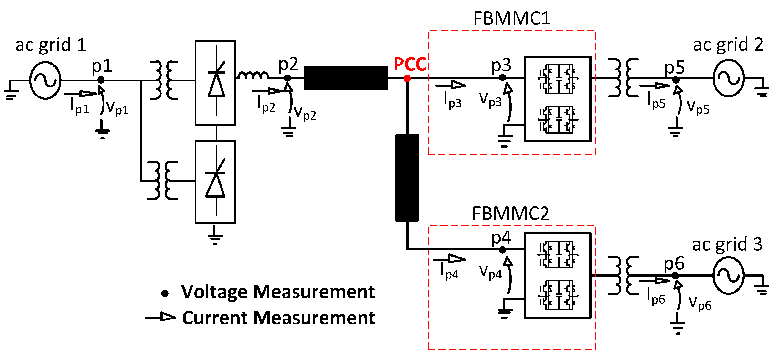
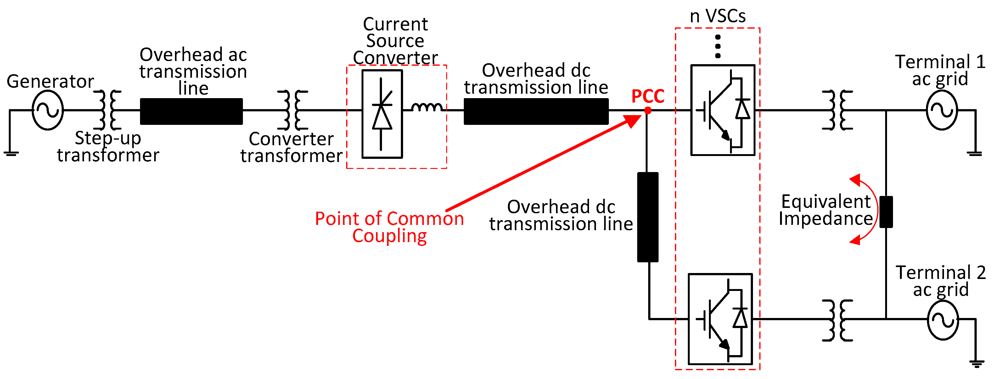
2.1. System Configuration

Figure 2 shows the analyzed hybrid system topology with one 12 pulse thyristor-based CSC operating as rectifier connected through a DC overhead transmission line to two FBMMCs operating as inverters.
The measurement points p1 to p6 in Figure 2 are used to guide the simulations. The connection among all the converters is done through an overhead DC transmission line that is represented by its distributed parameters. In this model, the resistance, inductance and capacitance parameters are given as per length (km). The point of common coupling (PCC) in Figure 2 is the point where the DC transmission line backbone is split to connect others MMCs trough DC transmission line branches.
The FBMMC configuration with N submodules in each arm is shown in Figure 3.
Full-bridge MMC allows to control the DC short-circuit current and its application is suitable in case of a HVDC with overhead transmission line. The control of the DC short-circuit current is not possible if conventional two or three level VSC or HBMMC is used because they have uncontrollable DC short-circuit current paths.

2.2. Control System

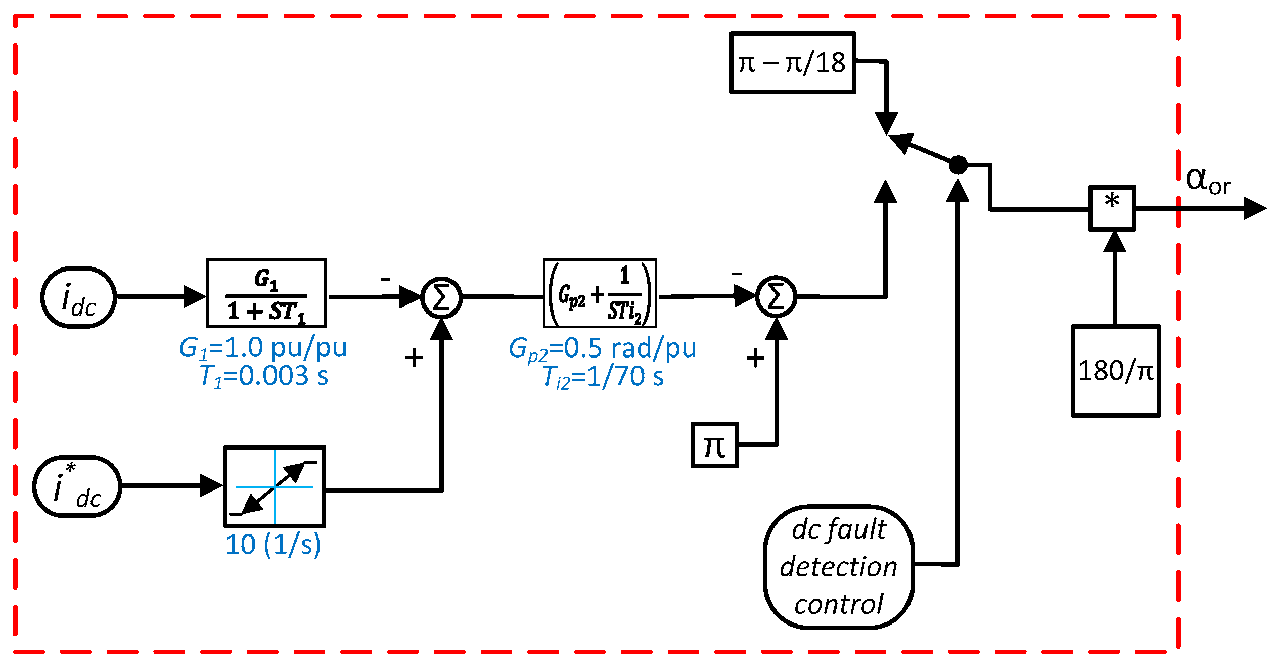
2.2.1. Current Source Converter

The control of the 12-pulse current source converter, in this study, considers only DC current control mode with the same controller type as in [9]. In this mode, the DC current reference is the input of the controller and the firing angle value of the thyristor is its output.
The DC current reference value is defined as i*dc. In Figure 4, when the block DC fault detection control detects the overcurrent, the DC protection scheme is activated.

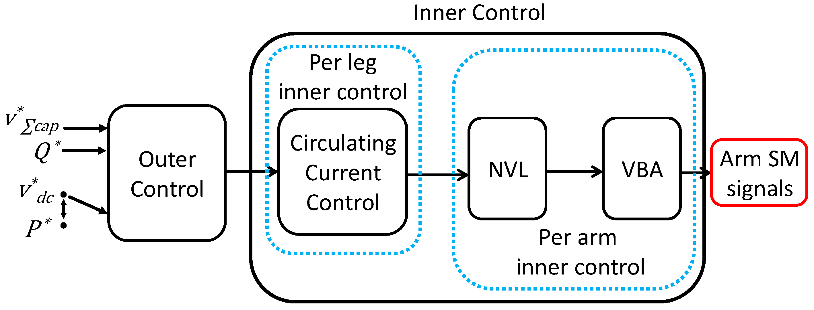
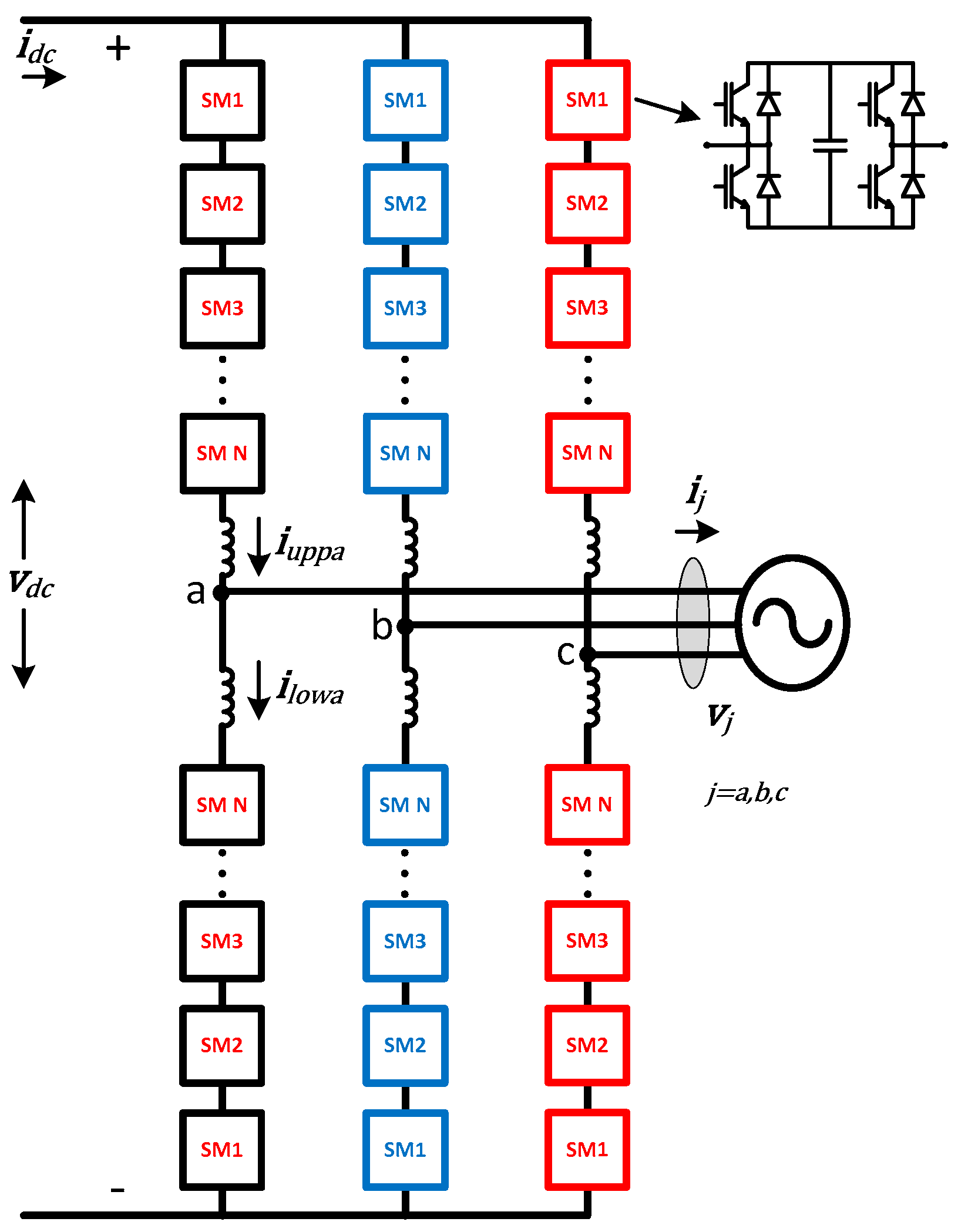
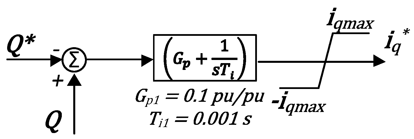
2.2.2. The Voltage Source Converter (FBMMC)

The control philosophies applied to FBMMC1 and FBMMC2 are:
  • FBMMC1 operates controlling DC voltage and reactive power;
  • FBMMC2 operates controlling active and reactive power.
The control applied in the FBMMC1 and FBMMC2 was based on vector control theory with some special parts such as circulating current control and voltage balancing algorithm (VBA) before the MMCs receive the switching signals. Figure 5 shows the block diagram of the complete control sequence for both FBMMCs. In this figure, Outer Control means the control of the active and reactive power that flows into the converter; in the Inner Control, the NVL block stands for the nearest voltage level modulation control (NVL); and the VBA block is the SM capacitor voltage balancing block (VBA). More details on the control sequence applied to FBMMC1 and FBMMC2 can be seen in [13]. In both converters, active and reactive power are controlled. At FBMMC1 the real power is used to control the DC-link voltage. At FBMMC2 the real power is an order that this converter has to inject in the AC grid.
The reactive power control loop used in FBMMC1 and FBMMC2 is shown in Figure 6. The variable Q in Figure 6 is the reactive power calculated (measured) using dq reference frame.
FBMMC1 is set to control the DC voltage of the H2VDC system, at the PCC, to give the voltage reference of the system. In steady-state condition, DC voltage at FBMMC2 and at CSC is given by Ohm’s law and depends on the direction of the DC current flow. The block diagram for DC voltage control and for the capacitor’s voltages control (CVC) used in FBMMC1 is shown in Figure 7 as in [12]. The gain K is used to set the sensibility of the CVC.
As it was said before, FBMMC2 is set to control its active power, which control block diagram is shown in Figure 8. The variable P in the sum block is the active power calculated using the dq reference frame. The CVC used in FBMMC2 is also presented in Figure 8 as in [13].
The control loops described in Figure 6, Figure 7 and Figure 8 generate the current reference signals on d (id*) and q (iq*) axes that are compared with the respective measured currents on d and q axes. These reference signals are the input of the current control loop that gives the voltage output on d and q axes (vd* and vq*), as shown in Figure 9. Figure 6, Figure 7, Figure 8 and Figure 9 compose the outer control. The PI controllers are adopted here because they are widely used for HVDC applications.
Figure 10 shows the block diagram for the circulating current control. Figure 10a shows the leg common voltage v*diffj calculation, which is composed basically by the control of the second order harmonic (2ω, where ω is the grid frequency) and for the zero-sequence control [14]. Figure 10b shows the voltage reference calculation for upper and lower arms. It is important to note that the DC voltage reference v*dc is the one ramped up during the start-up and re-start procedure of the FBMMCs and it is kept equal to zero during a DC fault.
As the FBMMC are composed by 20 SM per arm, there is no need for pulse width modulation (PWM)-based modulation techniques in order to have low harmonic voltage waveform, so a nearest voltage level (NVL) modulation technique was adopted in the simulation studies [15]. The time step for the simulation studies was 10 µs and the modulation verification was applied with intervals of 200 µs.

2.3. Master-Slave Control

HVDC multiterminal systems can be controlled through the so-called master-slave control philosophy. In this case, the master converter controls the system DC voltage and the other connected converters are slaves controlling active power, frequency or another variable. For the H2VDC system discussed in this paper there are two main possibilities to implement the master-slave approach. The first one is to consider the CSC as the master, which means that it would control the system DC voltage and all FBMMC would control its active power. The second—the one adopted in this paper—is to consider the CSC (rectifier) controlling active power (which is conventional for CSC-HVDC) and one FBMMC as the master converter controlling the DC voltage and the other FBMMC controlling the active power. By using this strategy, one can note that the power to energize the DC line will come from the AC grid 2 in Figure 2. After the DC voltage reaches the rated value, the CSC is set to deliver power to the multiterminal system. After the previous action, the FBMMC2 is set to dispatch active power.

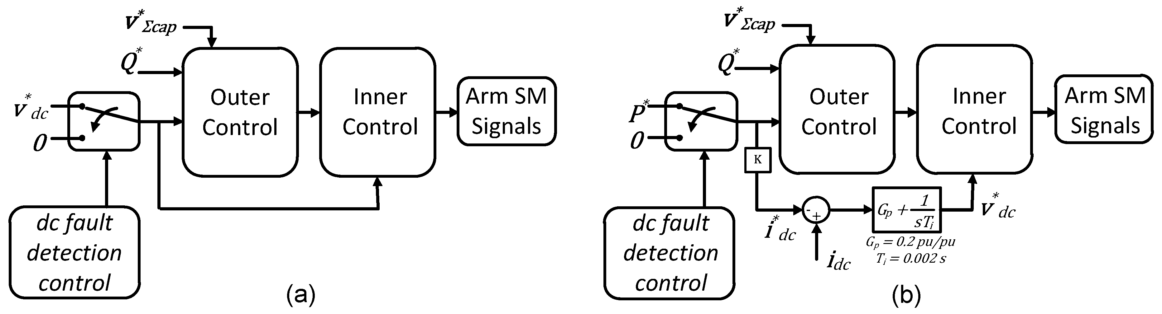
2.4. Dc Faults Protections and Management

The DC fault protection scheme adopted in this study considers overcurrent and undervoltage to detect the fault. The measured DC current value that triggers the DC fault scheme is set at 2 pu. The time delay to start the DC fault handling after the current crosses the overcurrent limit is 100 µs. After the fault detection, the CSC overcurrent strategy is to increase the firing angle up to its maximum value adopted in this study: 170 degrees.
There are two ways to interrupt the DC current during a DC fault using a FBMMC:
  • Blocking all the IGBTs and forcing the DC current to flow through the SM capacitors; or
  • By control actions, forcing the DC voltage or the DC current fall to zero.
In the first case, the usual strategy to interrupt DC short-circuit current using FBMMC is to block all switches so the current between the AC and DC sides are forced to flow through the series connection of all SM capacitors and the current is quickly blocked [10]. In this case, it is expected that the total current interruption takes approximately 5 ms after the detection of the DC short-circuit. However, considering this approach, the converter cannot control reactive power during the DC short-circuit. Therefore, in this paper it is proposed to use the second option, where the FBMMC DC voltage reference is set to zero and the DC current short-circuit goes to zero. This action of control is slower than the all switch blocking strategy (first option) and is expected that the short-circuit current interruption takes approximately 40~50 ms after DC short-circuit.

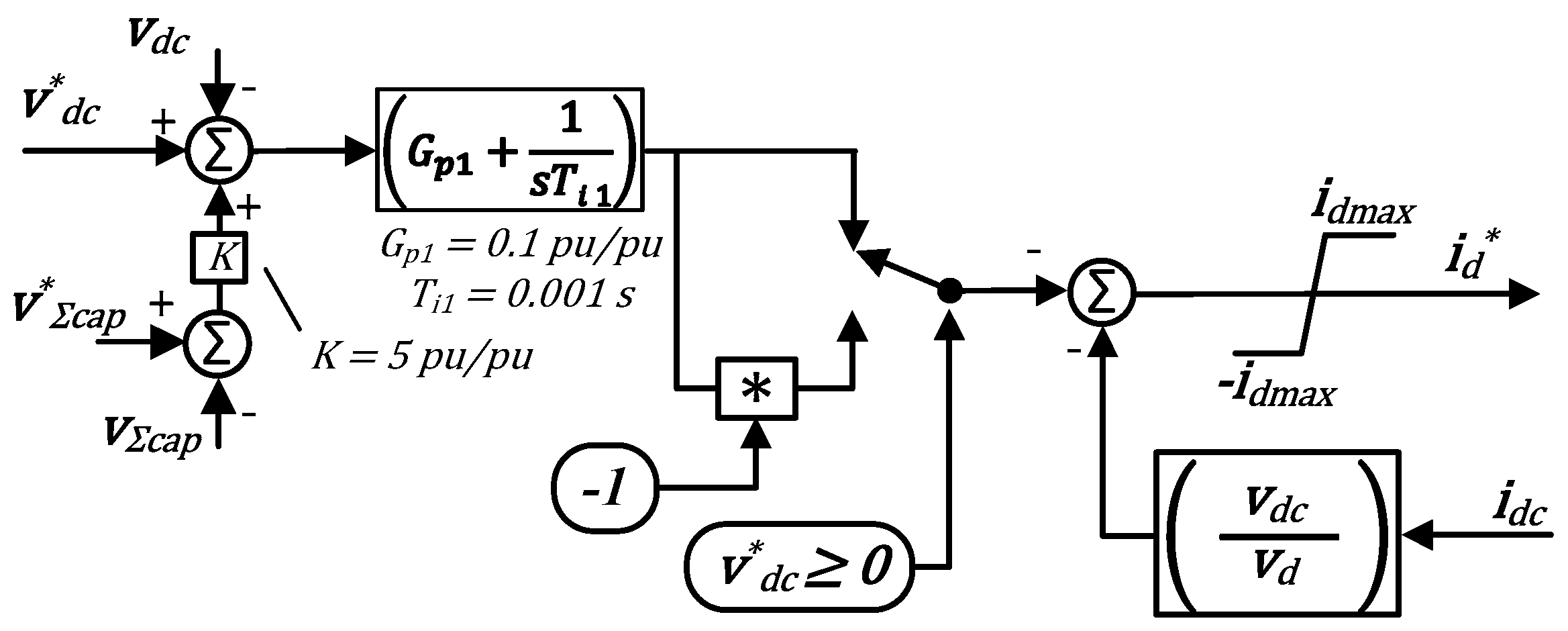
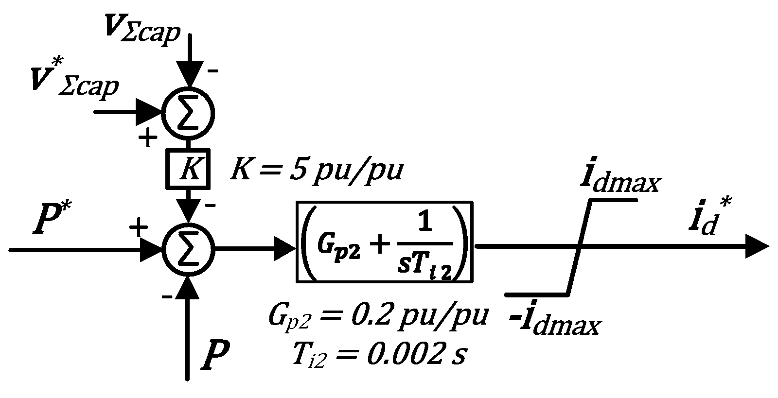
2.4.1. Dc Voltage Control Under Short-Circuit Condition

The DC fault handling without blocking all the switches comes up with a different issue: the control of DC voltage reference at all FBMMC. For conventional HBMMC, the DC voltage reference is generally kept at the rated value. However, in this case there is a need for surge arresters to avoid overvoltage transient when starting the system (or recovering after faults). For the FBMMC, the DC voltage may be softly controlled by regulating the desired DC voltage reference, which is the approach adopted to handle the DC current fault in this paper.
Figure 11 shows the influence of the DC fault detection control on the FBMMC overall control. After the fault detection, the FBMMC1 DC voltage reference is set to zero and the FBMMC2 DC current reference is set to zero in order to avoid the converters to feed the DC short-circuit. After the deionization time, the converter FBMMC1 is supposed to restore the voltage level at the DC line. This control action is done by ramping up the FBMMC1 DC voltage reference to the rated value. As the DC voltage starts to be restored to its rated value, the FBMMC2’s DC current control regulates its own DC-side voltage by controlling its reference value v*dc and keeping its DC current controlled. The objective of this action is to avoid the FBMMC2 to become a short-circuit for the DC system or present an uncontrolled DC current.
It is important to discuss about v*dc in Figure 11. By using FBMMC it is possible to decouple the AC and DC sides of the converter as discussed in [12,13], so it is possible to control separately the active power from both sides. However, if the active power from one side is set independently from the other, the energy stored inside the converter’s capacitors will fall or rise undesirably unless the capacitors are connected to an energy storage system such as batteries. The FBMMC1, as discussed in Section 2.3, is set to control the DC voltage. Therefore, the active power that flows at the FBMMC1’s AC side is the amount of power left in the DC system, which makes FBMMC1 to work in slack mode at the DC system.
The concept of decoupling between AC and DC sides can be observed in the FBMMC2’s control depicted in Figure 11. Usually, for a slave converter in an HVDC system, the AC active power reference P* is controlled by the slave converter while the system DC voltage is kept controlled by the master converter. This is not the case for an FBMMC. The control of the FBMMC2 must take advantage of the decoupling between the converter AC and DC sides into account and set a reference for its DC voltage independently from the AC side active power. Once the DC voltage is controlled by the master converter (FBMMC1), FBMMC2 (and any other slave FBMMC connected to this multiterminal grid) must be set to control its DC-side current and then provide a DC voltage reference for the inner control as shown in Figure 11b. As the HVDC system’s DC side current presents a constant mean value in normal operation, a PI controller has been adopted in this paper to set the DC voltage reference needed to regulate the DC-side current. One can note that the same reference is adopted for the active power in the outer control and for the DC-side current (with a gain K to convert the units) to generate the voltage reference v*dc for the FBMMC2. This strategy is supposed to guarantee power transfer between AC and DC sides without charging or discharging the SM capacitors. However, this approach still does not consider the losses inside the converter, which would provoke a slow decrease in the energy stored inside the capacitors. To avoid this problem, the CVC described in [13] is adopted for the whole operation inside the outer control, not only when v*dc = 0. For the FBMMC1, the CVC is only needed while v*dc = 0.
Once FBMMC2 is set to control the DC current, a DC short-circuit might not be sufficient to trigger the overcurrent protection. Therefore, this converter is also set to detect a DC fault when a sudden DC voltage dropdown occurs.

3. Simulations

The simulations developed here are used to study the performance of the H2VDC system shown in Figure 2—with one CSC and 2 FBMMC—in normal and some emergency conditions. This section shows the DC fault handling capability of the proposed hybrid system. Besides, it shows the system behavior during a pole-to-ground fault. In the studied system the CSC and FBMMCs are rated at 1000 MVA and 500 kV DC voltage. The simulation considers that capacitors of both FBMMC1 and FBMMC2 are previously charged. Table 1 presents the main parameters. The SM voltage was chosen equal 25 kV and thus would need series switches, which is not normal for MMC. This choice decreases the number of SM and makes faster the simulation. The practical SM voltage in actual applications with single switches is in the order of 2 kV.

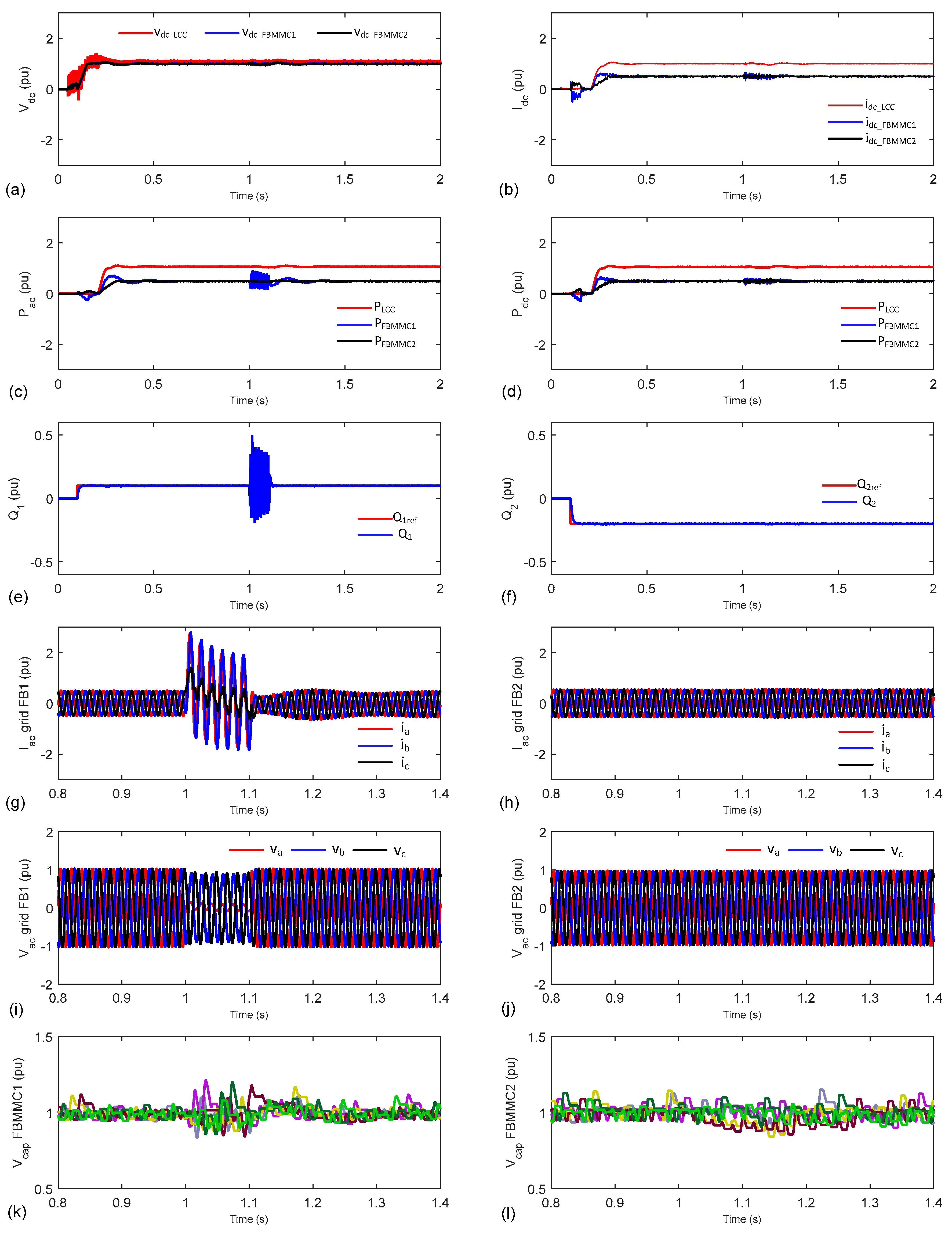
3.1. Single Phase Short Circuit at the AC Grid 1

Figure 12 shows the H2VDC system behavior during a single-phase short-circuit at phase a of the AC grid 2, as shown in Figure 2. It is considered a non-permanent AC short-circuit. The short-circuit is applied at t = 1 s and lasts for 100 ms. In this case, there is no special protection scheme developed for AC faults.
Based on the simulations in Figure 12, it is possible to conclude that the proposed H2VDC system presents a stable dynamic performance during an AC short-circuit. After the AC fault extinction, the H2VDC system returns to all its fault previous value. Figure 12a shows that the DC voltage is not affected significantly in this case. The transmitted DC power at the rectifier, as shown in Figure 12d, has just a little transient, which is a great advantage over pure CSC-HVDC system. Figure 12g–j show the AC currents and voltages with a zoom in from 0.8 s to 1.4 s. Figure 12k–l show the capacitors voltages on FBMMC 1 and 2 also with a zoom. The soft oscillatory behavior in both converters is due to the oscillation in the DC currents at the converter terminals during the DC short-circuit, as shown in Figure 12b.

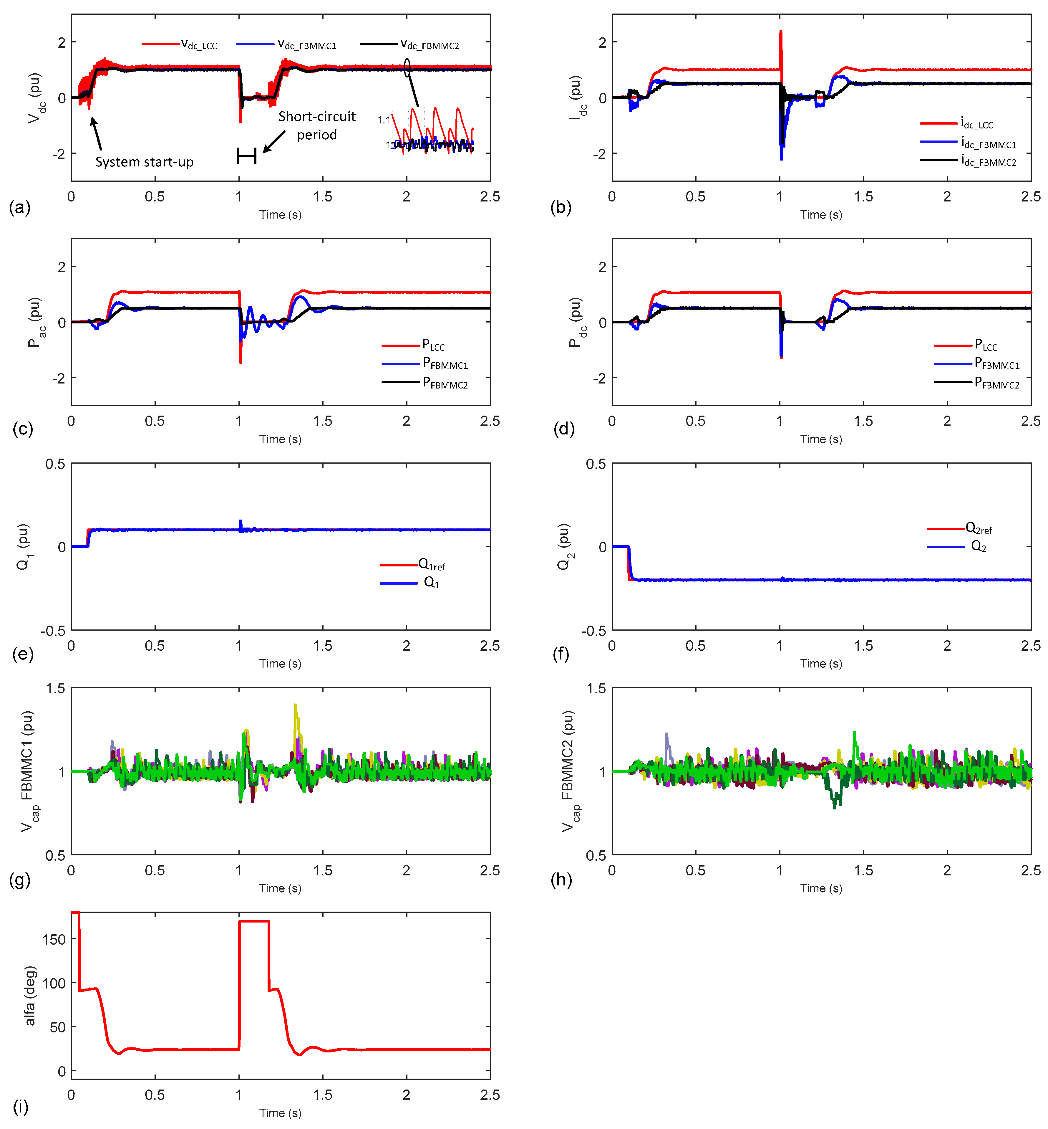
3.2. Short Circuit At the DC Line

Figure 13 shows the H2VDC system behavior during a short-circuit at the DC line backbone. In this case, it is considered a non-permanent DC short-circuit at the DC line, with duration of 100 ms. DC protection schemes described in detail in Section 2 are activated here.
The CSC converter is set to control the DC current. The FBMMC1 is set to control the DC voltage and FBMMC2 is set to control its active power flow. Both FBMMC keep controlling its reactive power. At the instant 0.05 s, CSC is turned on with its current reference set to zero. Then, at the instant 0.1 s, FBMMC1 DC voltage reference is ramped up to 1 pu at a rate of 20 pu/s, thus, it reaches 1 pu in 50 ms. The FBMMC2 was turned on at the instant 0.15 s. Also, at this time, the current reference at the CSC is ramped up from 0 to 1 pu at a rate of 10 pu/s, thus, it reaches 1 pu in 100 ms. The power reference for the FBMMC2 is ramped up at the instant 0.2 s with the rate of 5 pu/s. After these operating sequences, the H2VDC system reaches its steady-state operation.
At t = 1 s, a DC short-circuit is applied at the DC line backbone. At this moment, the DC current grows up and the DC voltage goes down. Therefore, considering the measured overcurrent and undervoltage values, the DC protection of each converter get into operation: the firing angle of the CSC is set to its maximum value by its control action; the FBMMC1 DC voltage reference is set to zero; and the FBMMC2 active power reference (and i*dc) is set to zero. Then, after the set deionization time of 200 ms, the CSC is set to control zero active power, so, the CSC firing angle alfa goes around 90°. After 200 ms of the FBMMC1 fault detection, the FBMMC1 DC voltage reference is ramped up to 1 pu at a rate of 20 pu/s. After 250 ms of the CSC fault detection, the CSC power reference is ramped up at a rate of 10 pu/s. After 300 ms of the FBMMC2 fault detection, the FBMMC2 power reference is ramped up also with 5 pu/s.
Figure 13a shows that the DC voltage of the system is set to zero in order to eliminate the DC short-circuit current. In Figure 13a there is also a zoom that shows the DC voltages waveforms measured at all converters terminals in normal operation. In Figure 13b, it is possible to analyze that the DC short-circuit current is controlled by the control actions of all converters (CSC and FBMMCs) together. Figure 13c,d show the active power measured at both AC and DC sides of the converters. Figure 13e,f show that FBMMC1 and FBMMC2 operate as STATCOM during the DC short-circuit time, being it a great advantage over other VSCs. This is possible by the fact that the IGBTs are not blocked during the DC short-circuit. In fact, as discussed in Section 2.3., the FBMMC control adopted allows the independent control of its AC and DC voltages [12,13].
Figure 13g,h show FBMMC1 and FBMMC2 capacitors voltages. The initial short-circuit current causes the capacitors voltages to decrease, but, during the deionization time, the capacitor’s voltage control is set to keep it in the nominal value.
Figure 13i shows the firing angle behavior of the CSC. When the CSC control detects an overcurrent more than the set value (idc > 2 pu), it elevates the firing angle to its maximum value (170 degrees) with the purpose of reducing the DC current. After the deionization time (200 ms), the CSC control sets the firing angle at 90 degrees to zero power during 50 ms to wait the system DC voltage be restored again to 1 pu. After the DC voltage restoration, the CSC firing angle is set to its nominal value again to transmit DC power normally.
In this case, the H2VDC system returns to its normal operation approximately 400 ms after the DC short-circuit is applied. It is important to note that all the time spent in the system’s restoration process can be set to be faster or slower depending on the system parameters and requirements.

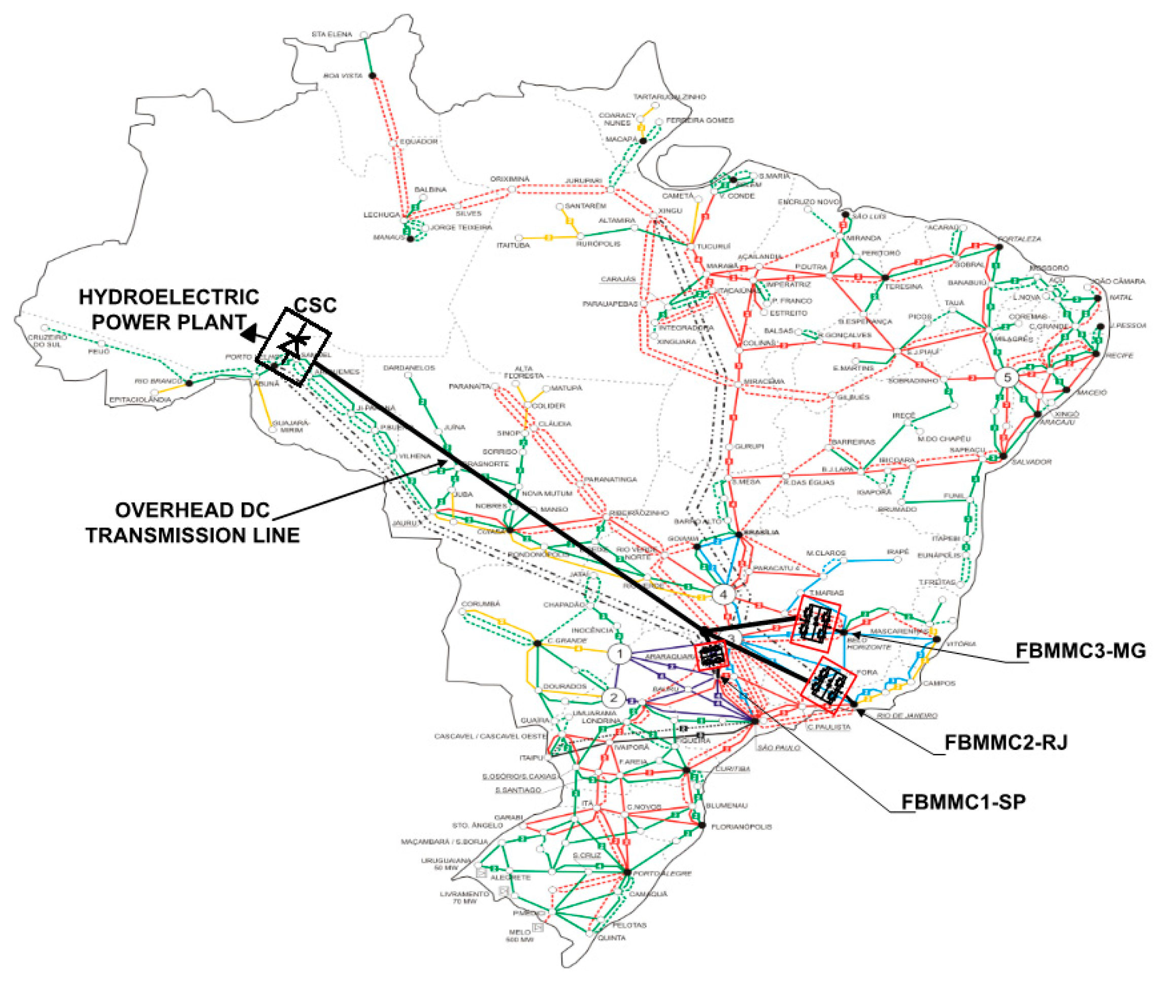
4. Possible Application

One possible practical application of the H2VDC system is the power transmission from a large hydroelectric power plant located in the Amazon region to the main load centers in Brazil (Rio de Janeiro, São Paulo and Minas Gerais) in a multiterminal configuration (CSC and FBMMCs). Figure 14 shows a simplified map of the Brazilian electrical system with the H2VDC system highlighted inside in black.
In Figure 14, the CSC is connected directly in a hydroelectric power plant to convert (AC to DC) all the generated power. This converted power is transmitted through an overhead DC transmission line directly to the 3 FBMMCs that are connected at the Brazilian main load centers. All the benefits of the FBMMCs shown before could be applied to the operation of each AC receiving system (hypothetically, Rio de Janeiro, São Paulo and Minas Gerais). As discussed in Section 2.4.1, the third FBMMC would be controlled with the same strategy used for FBMMC2 in the simulation studies. Considering strong AC systems and an operation as rectifier, the use of CSC is extremely recommended, more power can be transmitted, and the total cost will be reduced in comparison with a pure MMC system.
In steady-state condition is expected that the transmitted power is unidirectional, which means that the CSC operates as rectifier and the FBMMCs operate as inverters. In special conditions it could be possible that any FBMMC operates as rectifier interchanging power among the FBMMCs when an AC grid has power excess and the other AC grid has power deficit. All these characteristics can improve the operation of the power system.

5. Conclusions

The analyses of the H2VDC system study and dynamic performance were shown in detail in the simulations. These simulations have considered operating conditions of single phase AC short-circuit at AC grid 1 and short-circuit at the DC line backbone. Considering these operating conditions, the H2VDC system presented a stable dynamic performance returning to its normal operating conditions.
The AC single-phase short circuit simulation study has shown that the H2VDC system is not affected by single-phase AC faults, so there is no need for further actions but wait until the fault condition to be extinct. The AC single-phase short-circuit was analyzed here because in many countries its response is considered to be a planning criterion.
This paper presented a discussion on how to handle DC faults in a hybrid multiterminal DC transmission system without the need of DC breakers, power diodes in series with the converter and surge arresters. In addition, this approach allows reactive power control at the AC grids connected to the FBMMC even during the DC faults, adding a great advantage to the system over blocking the IGBTs. The normal operation of the studied system was reached after approximately 400 ms the DC short-circuit happening.
The DC short-circuit analysis considered in this paper is a non-permanent fault, which means that the DC short-circuit is self-extinguished after the voltage is forced to zero. If the DC short-circuit at the overhead DC line persists after the recovering strategy discussed in this paper, some attempts to re-start should be implemented to confirm that the fault is permanent and then, turn off the converters in order to start the maintenance procedure.
The simulations have shown that the technology of FBMMC was successfully applied in the operation of the H2VDC systems with overhead transmission line by the fact that the DC short-circuit current can be controlled.
The black start capability of the MMC is not analyzed in this paper. The used control does not allow the “black-start” and it would be necessary to develop this control to apply this function.
This paper proposes a DC voltage control strategy to restore the system normal operation after the DC faults without overcurrents or overvoltages and no need for critical communication between two stations. By controlling the DC voltage with the master FBMMC and the DC current with the slave converters, the proposed strategy assures that there will be no overcurrents among the FBMMC.
Based on the theoretical development and the simulation results shown here, the H2VDC system may become a very promising HVDC multiterminal transmission system, which improves the operation of power systems, by making the system more reliable and safe.

Author Contributions

Conceptualization, J.R.L., P.M.M.P. and E.H.W.; Data curation, J.R.L.; Formal analysis, J.R.L. and P.M.M.P.; Funding acquisition, E.H.W.; Investigation, J.R.L., P.M.M.P. and E.H.W.; Methodology, J.R.L., P.M.M.P. and E.H.W.; Software, J.R.L.; Supervision, E.H.W.; Writing—original draft, J.R.L. and P.M.M.P.; Writing—Review & Editing, J.R.L., P.M.M.P. and E.H.W.

Acknowledgments

This work was partially supported by FAPERJ Grant CNE E02/2017 as well as by CNPq Grant No. 306243/2014-8 and No. 142147/2014-1.

Conflicts of Interest

The authors declare no conflicts of interest.

Glossary

v*dc, vdcDC voltage reference and measured, respectively.
i*dc, idcDC current reference and measured, respectively.
vjabc phase-to-neutral voltages at the AC bar for j = a, b, c.
ijabc line currents at the AC bar for j = a, b, c.
iuppa, ilowaPhase a upper and lower arm currents.
P*, PThere-phase active power reference and measured, respectively.
Q*, QThere-phase reactive power reference and measured, respectively.
αorAlfa order for the CSC.
ωGrid frequency.
vd*, vd, id*, idd axis voltage and current references and measured, respectively.
vq*, vq, iq*, iqq axis voltage and current references and measured, respectively.
Gp, TiProportional gain and time constant for the PI controllers (empirically tuned).
KProportional gain to set the sensibility of the CVC error signal.
L, rReactance and resistance for decoupling the dq control.
idmax, iqmaxd and q axis maximum current limit for the outer control.
iuppj, ilowjUpper and lower arm currents for j = a, b, c.
v*∑capReference value for the sum of all capacitor’s voltages in one FBMMC.
v∑capSum of all capacitor’s voltages measured in one FBMMC.
v*jVoltages references from outer control output (vd*, vq*) for j = a, b, c.
v*diffjLeg common voltage for j = a, b, c.
vdc-baseDC base voltage.
vac-baseAC base voltage for the FBMMC.
v*uppj, v*lowjUpper and lower arm reference voltages for the modulation control for j = a, b, c.
NVLNearest voltage level modulation control.
VBAVoltage Balancing Algorithm.

References

  1. C-EPRI. Available online: http://www.cepri.com.cn/aid/details_72_272.html (accessed on 10 March 2018).
  2. Francos, P.L.; Verdugo, S.S.; Alvarez, H.F.; Guyomarch, S.; Loncle, J. INELFE Europe’s first integrated onshore HVDC interconnection. In Proceedings of the 2012 IEEE Power and Energy Society General Meeting, San Diego, CA, USA, 22–26 July 2012; pp. 1–8. [Google Scholar] [CrossRef]
  3. Portugal, P.M.M.; Watanabe, E.H.; Macedo, N.J.P. Hybrid HVDC system using current and voltage source converter. In Proceedings of the CIGRE CE-B4 Colloquium HVDC and Power Electronics to Boost Network Performance, Brasilia, Brazil, 2–3 October 2013. [Google Scholar]
  4. Portugal, P.M.M.; Watanabe, E.H.; Macedo, N.J.P. Study and development of a hybrid HVDC System composed by current and voltage source converters. In Proceedings of the XIII Symposium of Specialists in Electric Operational and Expansion Planning, Foz do Iguaçu, Brazil, 18–21 May 2014. [Google Scholar]
  5. Tang, G.; Xu, Z. A LCC and MMC hybrid HVDC topology with DC line fault clearance capability. Int. J. Electr. Power Energy Syst. 2014, 62, 419–428. [Google Scholar] [CrossRef]
  6. Lee, Y.; Cui, S.; Kim, S.; Sul, S.K. Control of hybrid HVDC transmission system with LCC and FB-MMC. In Proceedings of the 2014 IEEE Energy Conversion Congress and Exposition (ECCE), Pittsburgh, PA, USA, 14–18 September 2014; pp. 475–482. [Google Scholar] [CrossRef]
  7. Jung, J.J.; Cui, S.; Lee, J.H.; Sul, S.K. A New Topology of Multilevel VSC Converter for a Hybrid HVDC Transmission System. IEEE Trans. Power Electron. 2017, 32, 4199–4209. [Google Scholar] [CrossRef]
  8. Xu, Z.; Wang, S.; Xiao, H. Hybrid high-voltage direct current topology with line commutated converter and modular multilevel converter in series connection suitable for bulk power overhead line transmission. IET Power Electron. 2016, 9, 2307–2317. [Google Scholar] [CrossRef]
  9. Nguyen, M.H.; Saha, T.K.; Eghbal, M. Hybrid multi-terminal LCC HVDC with a VSC Converter: A case study of Simplified South East Australian system. In Proceedings of the IEEE Power and Energy Society General Meeting, San Diego, CA, USA, 22–26 July 2012. [Google Scholar] [CrossRef]
  10. Marquardt, R. Modular Multilevel Converter: An universal concept for HVDC-Networks and extended DC-bus-applications. In Proceedings of the 2010 International Power Electronics Conference—ECCE Asia—(IPEC), Sapporo, Japan, 21–24 June 2010; pp. 502–507. [Google Scholar] [CrossRef]
  11. Sharifabadi, K.; Harnefors, L.; Nee, H.P.; Norrga, S.; Teodorescu, R. Design, Control and Application of Modular Multilevel Converters for HVDC Transmission Systems; John Wiley & Sons: Hoboken, NJ, USA, 2016; ISBN 9781118851562. [Google Scholar]
  12. Wenig, S.; Goertz, M.; Prieto, J.; Suriyah, M.; Leibfried, T. Effects of DC fault clearance methods on transients in a full-bridge monopolar MMC-HVDC link. In Proceedings of the 2016 IEEE PES Innovative Smart Grid Technologies Conference Europe, Melbourne, VIC, Australia, 28 November–1 December 2016; pp. 850–855. [Google Scholar] [CrossRef]
  13. Lebre, J.R.; Watanabe, E.H. Fullbridge MMC control for hybrid HVDC systems. In Proceedings of the 2017 Brazilian Power Electronics Conference (COBEP), Juiz de Fora, Brazil, 19–22 November 2017; pp. 1–6. [Google Scholar] [CrossRef]
  14. Moon, J.W.; Kim, C.S.; Park, J.W.; Kang, D.W.; Kim, J.M. Circulating current control in MMC under the unbalanced voltage. IEEE Trans. Power Deliv. 2013, 28, 1952–1959. [Google Scholar] [CrossRef]
  15. Kouro, S.; Bernal, R.; Miranda, H.; Silva, C.A.; Rodríguez, J. High-performance torque and flux control for multilevel inverter fed induction motors. IEEE Trans. Power Electron. 2007, 22, 2116–2123. [Google Scholar] [CrossRef]
Figure 1. Proposed Hybrid HVDC System topology. PCC: point of common coupling.
Energies 11 01323 g001
Figure 2. Analyzed Hybrid HVDC system topology.
Energies 11 01323 g002
Figure 3. MMC topology with FBSM. SM: submodule.
Energies 11 01323 g003
Figure 4. Rectifier DC current control block diagram.
Energies 11 01323 g004
Figure 5. Control sequence of the FBMMC1 and FBMMC2. NVL: nearest voltage level; VBA: voltage balancing algoritm.
Energies 11 01323 g005
Figure 6. Reactive power control loop used in FBMMC1 and FBMMC2.
Energies 11 01323 g006
Figure 7. DC Voltage control loop for FBMMC1.
Energies 11 01323 g007
Figure 8. Active power control loop for FBMMC2.
Energies 11 01323 g008
Figure 9. Inner current controller block diagram for FBMMC1 and FBMMC2.
Energies 11 01323 g009
Figure 10. Circulating current control: (a) v*diff calculation; (b) upper and lower arms voltage reference calculation.
Energies 11 01323 g010
Figure 11. Overall FBMMC control considering the DC fault detection control: (a) DC voltage FBMMC controller—FBMMC1; (b) active power FBMMC controller—FBMMC2.
Energies 11 01323 g011
Figure 12. H2VDC system behavior during a single-phase fault at t = 1 s for 0.1 s in phase a of the FBMMC1: (a) DC voltage; (b) DC current; (c) AC active power; (d) DC active power; (e) AC current at p5 (FBMMC1); (f) AC current at p6 (FBMMC2); (g) AC voltage at p5 (FBMMC1); (h) AC voltage at p6 (FBMMC2); (i) reactive power at the AC side of FBMMC1; (j) reactive power at the AC side of FBMMC2; (k) FBMMC1 capacitor voltages; (l) FBMMC2 capacitor voltages.
Energies 11 01323 g012
Figure 13. System behavior during a DC fault: (a) DC voltages; (b) DC currents; (c) AC active power; (d) DC active power; (e) reactive power at the AC grid connected to FBMMC1; (f) reactive power at the AC grid connected to FB2; (g) FBMMC1 capacitor voltages; (h) FBMMC2 capacitor voltages; (i) CSC firing angle αor.
Energies 11 01323 g013
Figure 14. Hypothetical configuration of the H2VDC system for transmitting power from the Amazon region to the main load centers of Brazil with three FBMMC terminals (Rio de Janeiro, São Paulo and Minas Gerais).
Energies 11 01323 g014
Table 1. Analyzed H2VDC System parameters.
ParameterValue
Rated DC voltage500 kV
FBMMC Rated AC voltage280 kV
Rated DC power1000 MW
CSC AC system reactance150 mH
FBMMC1 AC system reactance42 mH
CSC transformers rated voltages345/220/220 kV
FBMMC transformers rated voltages280/280 kV
Transformers equivalent reactance0.15 pu
Transformers equivalent resistance0.001 pu
CSC smoothing reactance500 mH
FBMMC smoothing reactance50 mH
Number of SMs per arm20
SM rated voltage25 kV
SM capacitance1 mF
Arm inductance5 mH
FBMMC’s inertia constant, H37.5 ms
Line resistance per unit length0.015 Ω/km
Line inductance per unit length0.792 mH/km
Line inductance per unit length14.4 nF/km
Line 1 length1000 km
Line 2 length200 km

