Regulation of Voltage and Frequency in Solid Oxide Fuel Cell-Based Autonomous Microgrids Using the Whales Optimisation Algorithm

 ,
, 
Abstract
:1. Introduction
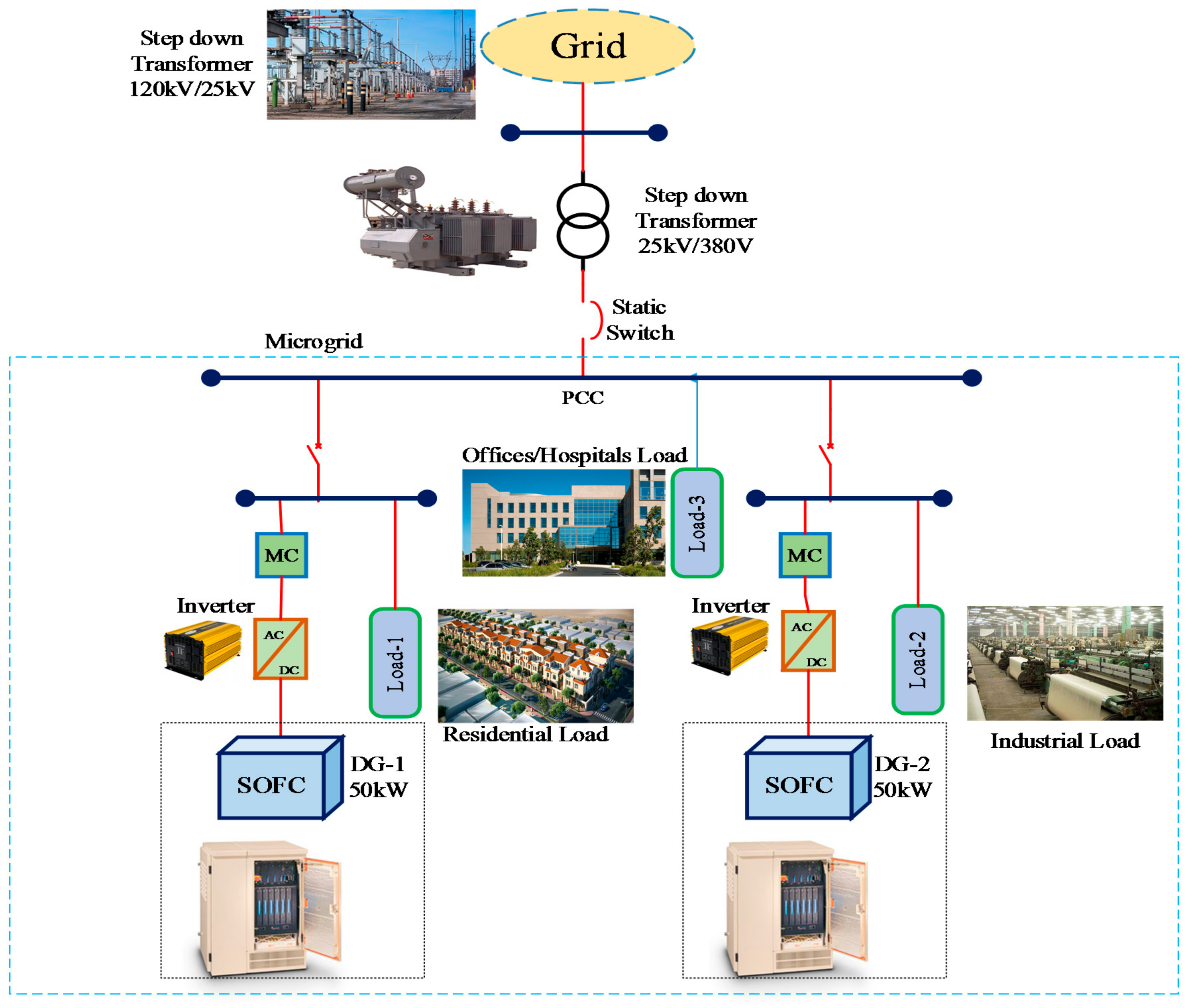
2. Microgrid
2.1. Structure of Microgrid
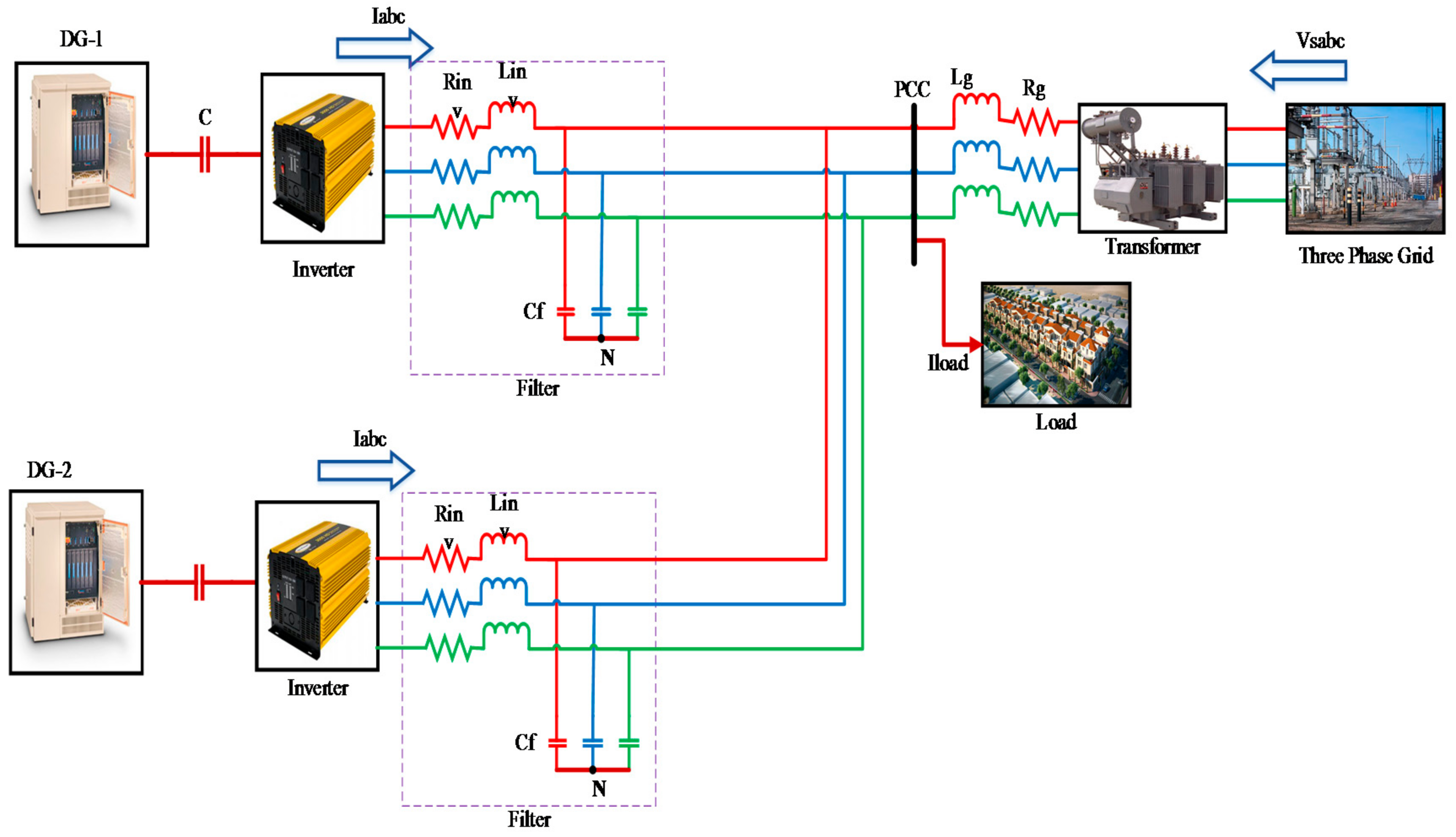
2.2. Three Phase Grid Modelling
2.3. Model of SOFC
3. Proposed Methodology
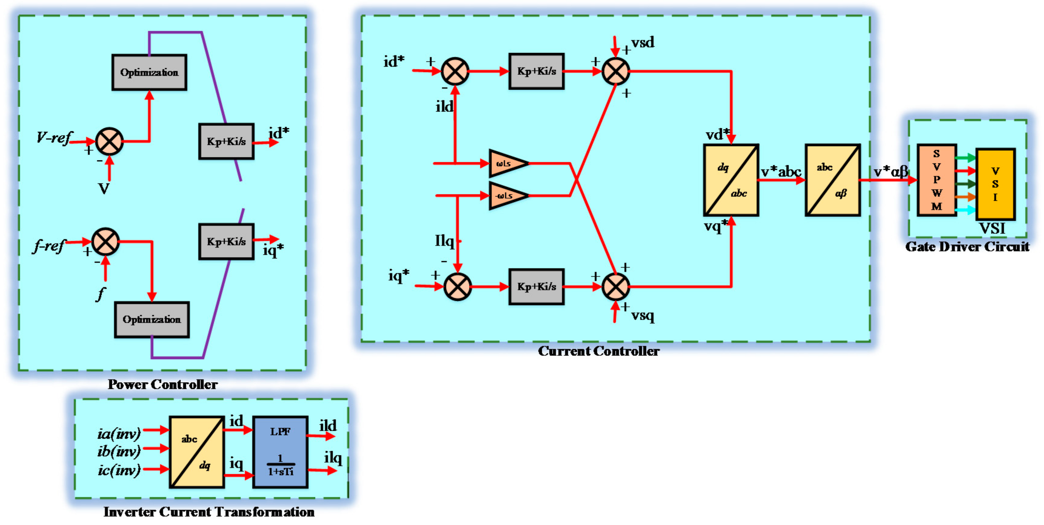
3.1. Control Strategy for VSI Based DG Unit
3.1.1. Power Controller
3.1.2. Current Controller
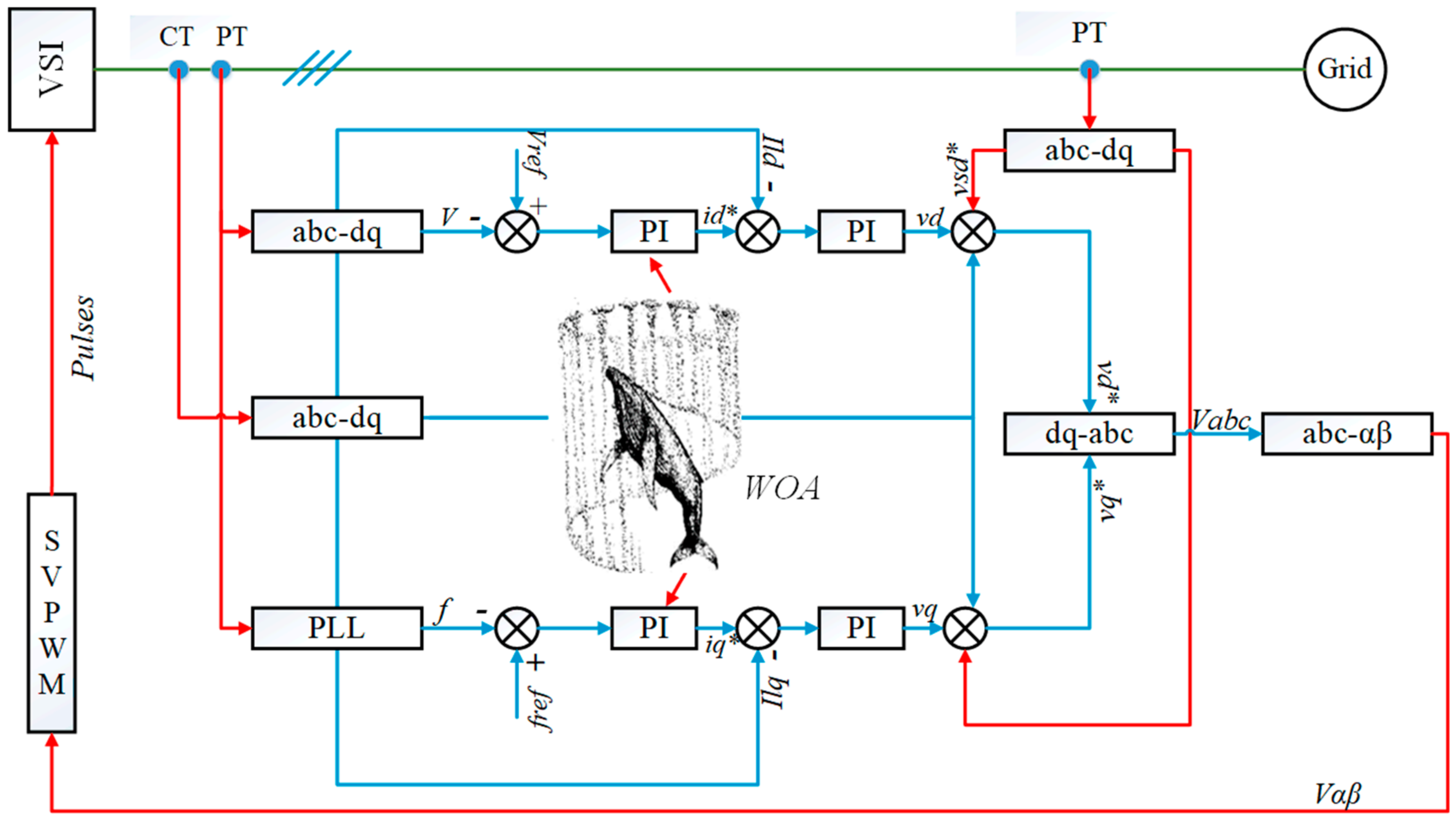
3.2. Design of WOA for Tuning of PI Controller Parameters
3.2.1. Control Structure Based on WOA for PI Controller
3.2.2. Whale Optimization Algorithm
3.2.3. Mathematical Formulation for devising of WOA
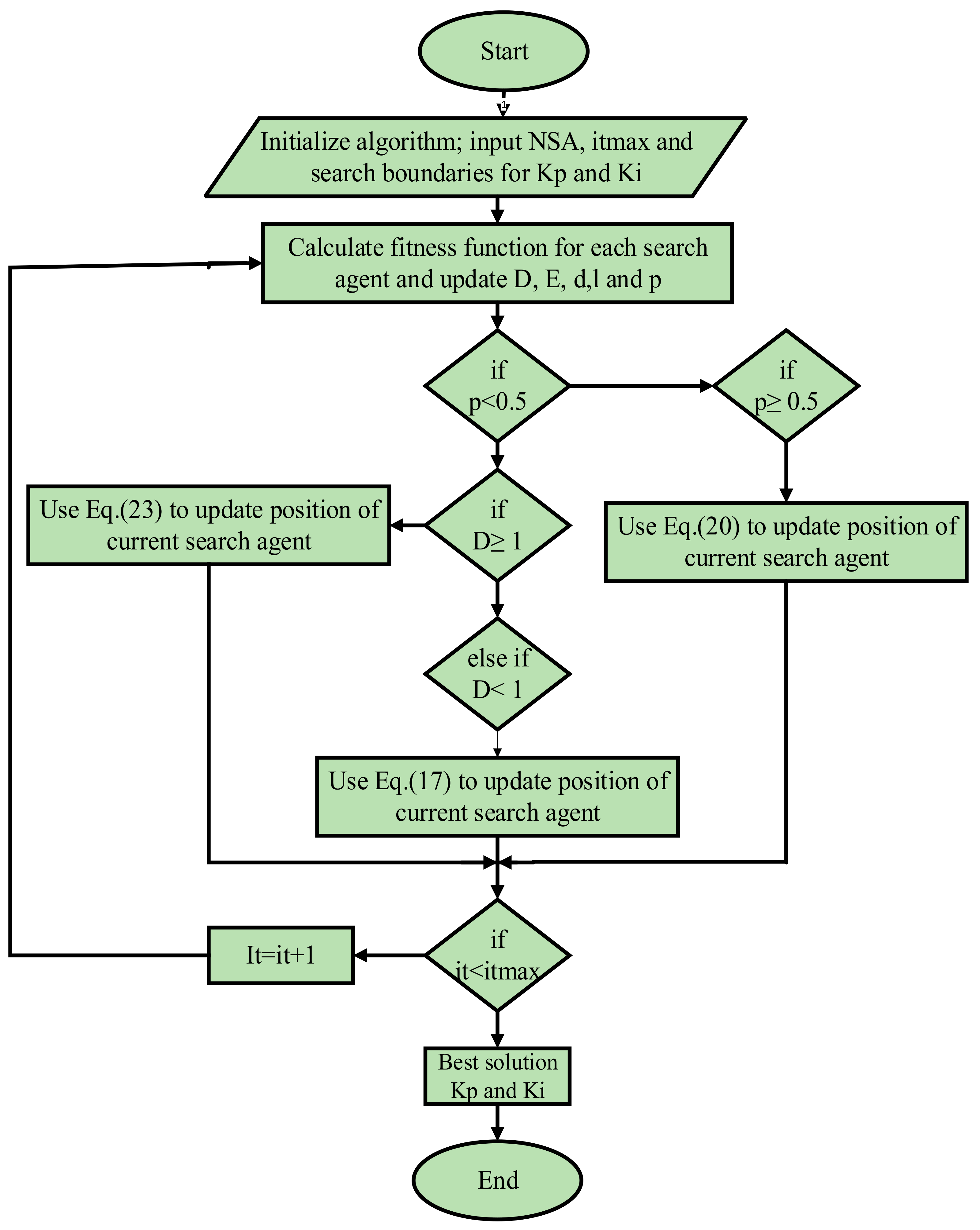
3.2.4. Algorithm for WOA to Obtain Optimal PI Controller Values
4. Case Studies and Proposed Test System
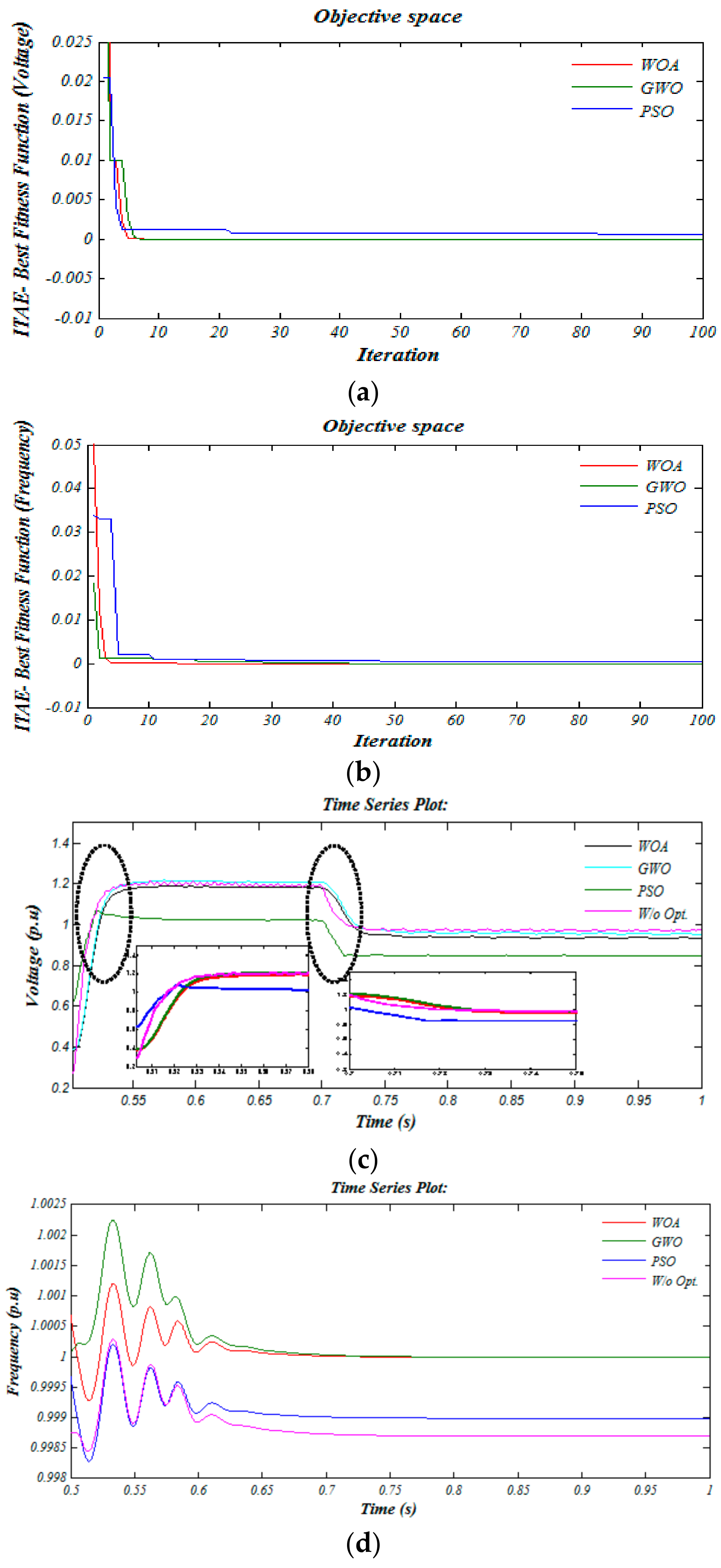
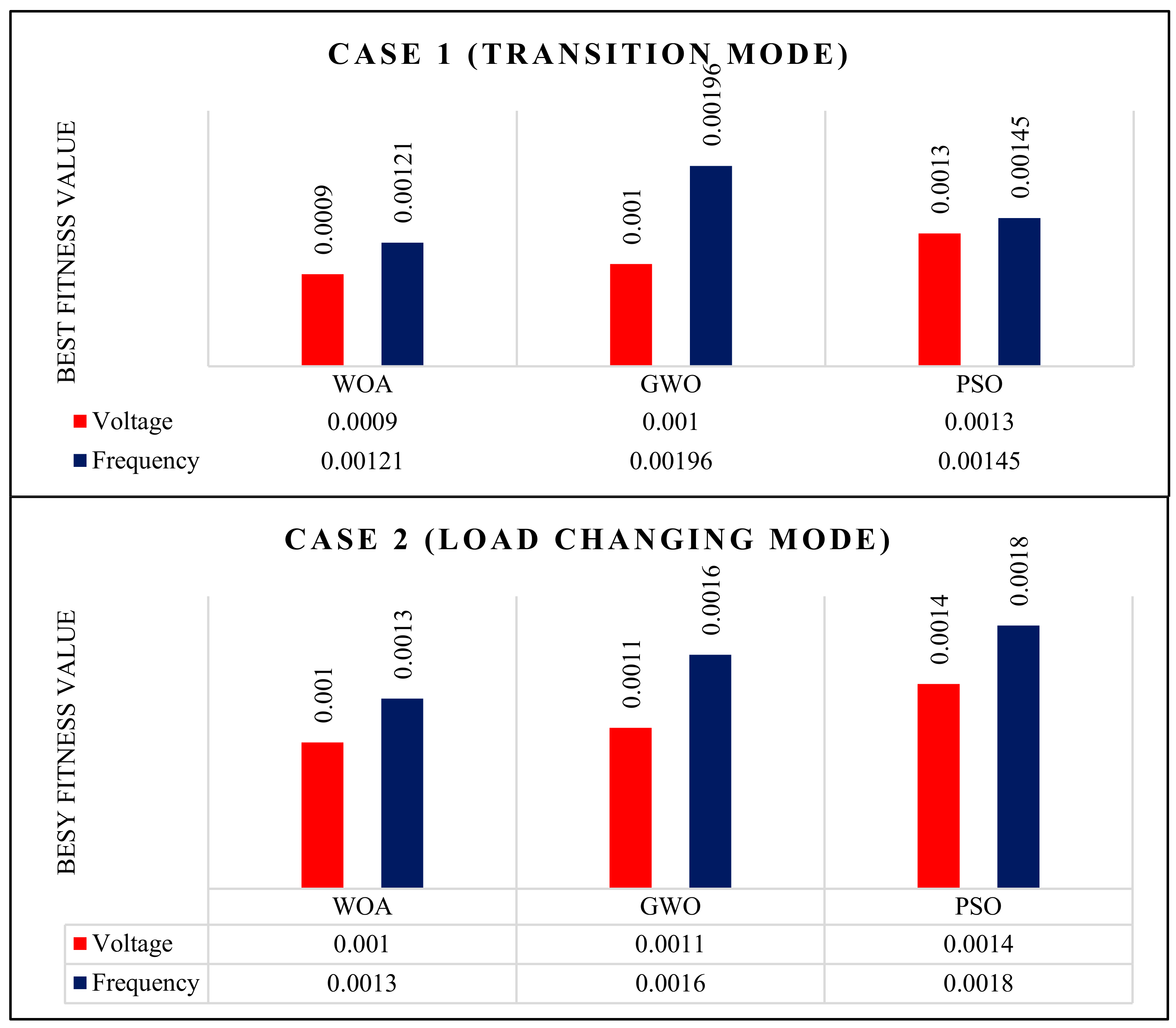
4.1. Simulation Results of Case 1 (Change in MGS Operation Mode)
4.2. Simulation Results of Case 2 (Load Changing)
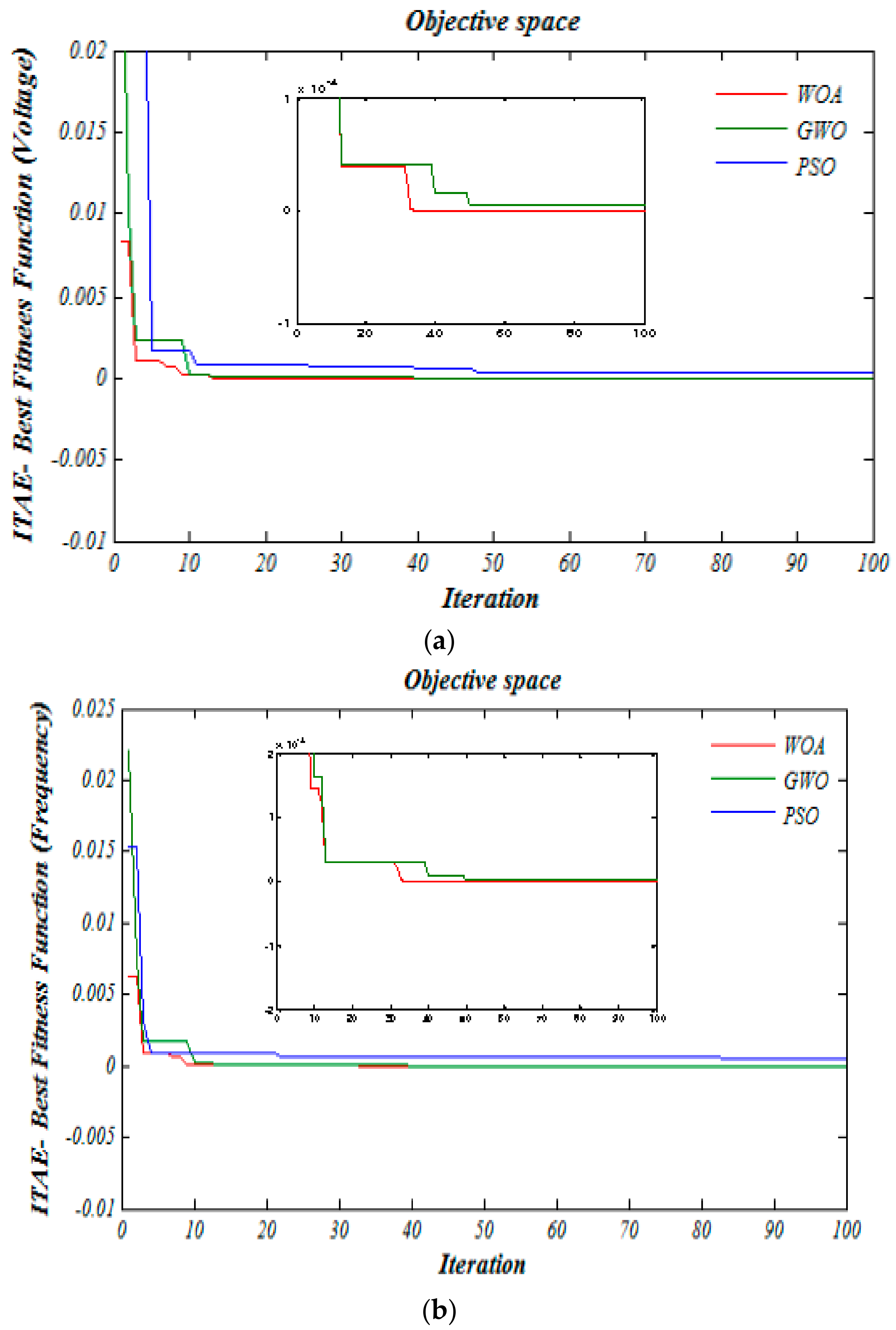
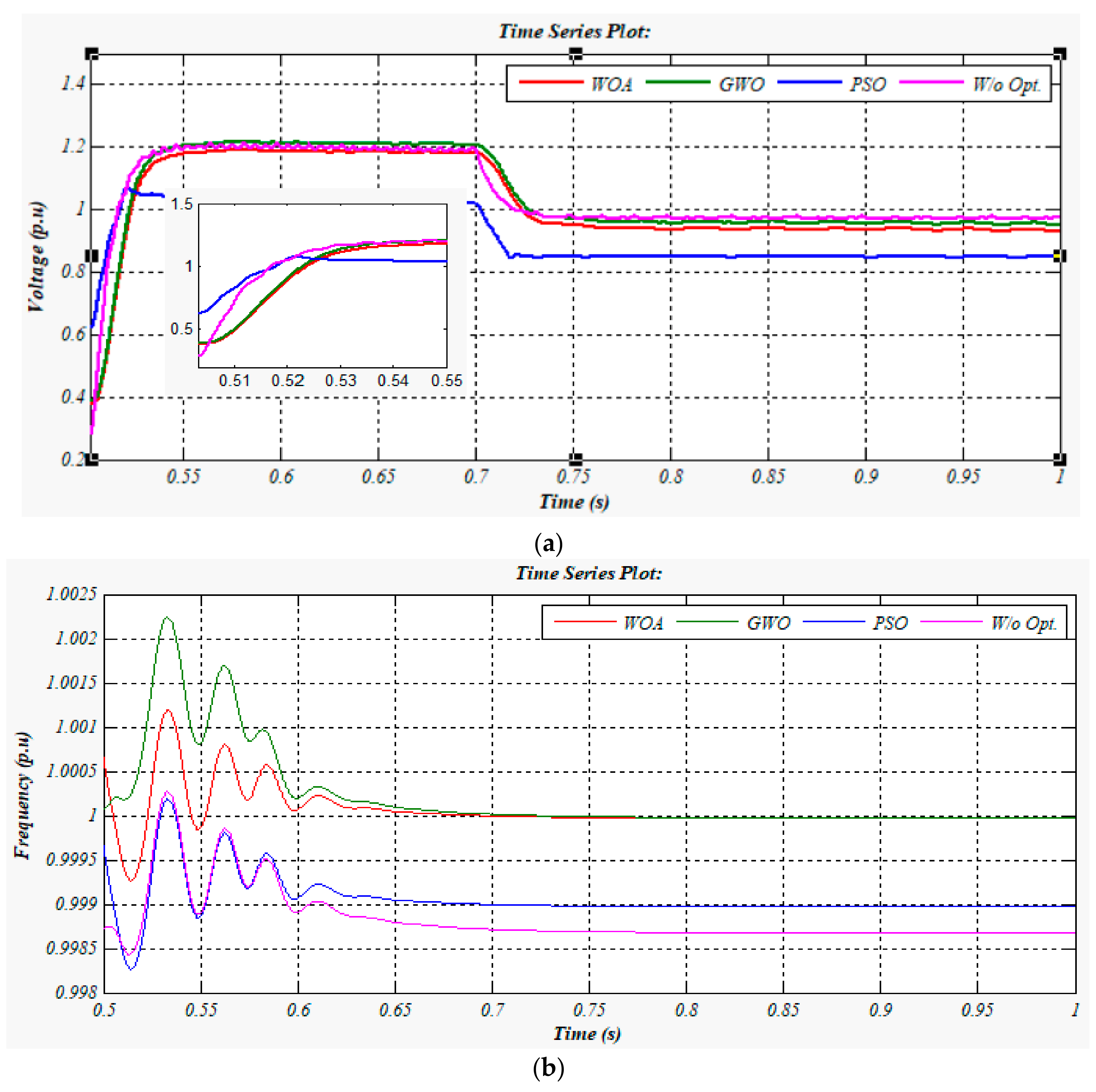
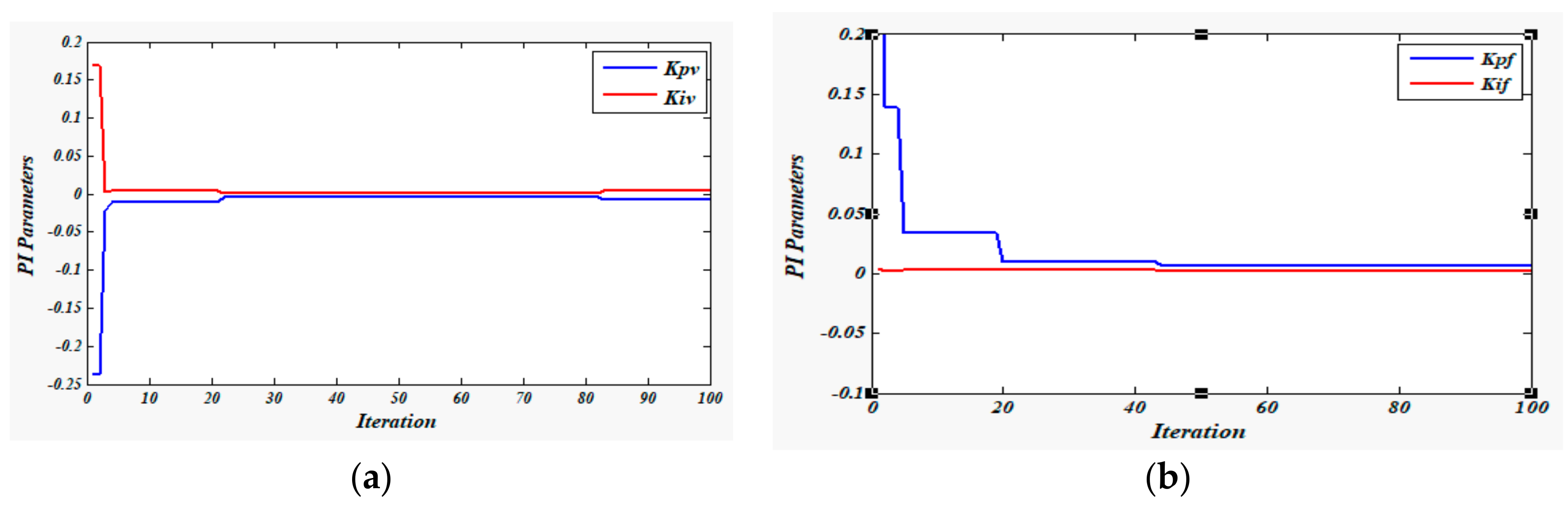
4.3. Comparative Results for both Cases
4.4. Eigenvalue Analysis
5. Conclusions
Author Contributions
Acknowledgments
Conflicts of Interest
References
- Lasseter, R.H.; Piagi, P. Control and Design of Microgrid Components; PSERC Publication 06; Power Systems Engineering Research Center: Ithaca, NY, USA, 2006; Volume 3. [Google Scholar]
- Hossain, E.; Perez, R.; Padmanaban, S.; Mihet-Popa, L.; Blaabjerg, F.; Ramachandaramurthy, V.K. Sliding Mode Controller and Lyapunov Redesign Controller to Improve Microgrid Stability: A Comparative Analysis with CPL Power Variation. Energies 2017, 10, 1959. [Google Scholar] [CrossRef]
- Hatziargyriou, N.; Asano, H.; Iravani, R.; Marnay, C. Microgrids. IEEE Power Energy Mag. 2007, 5, 78–94. [Google Scholar] [CrossRef]
- Qazi, S.H.; Mustafa, M.; Sultana, U.; Hussain, N. Enhanced Power Quality Controller in an Autonomous Microgrid by PSO Tuned PI Controller. Indian J. Sci. Technol. 2017, 10. [Google Scholar] [CrossRef]
- Katiraei, F.; Iravani, M.R. Power management strategies for a microgrid with multiple distributed generation units. IEEE Trans. Power Syst. 2006, 21, 1821–1831. [Google Scholar] [CrossRef]
- Katiraei, F.; Iravani, M.R.; Lehn, P.W. Micro-grid autonomous operation during and subsequent to islanding process. IEEE Trans. Power Deliv. 2005, 20, 248–257. [Google Scholar] [CrossRef]
- Chung, I.-Y.; Park, S.-W.; Kim, H.-J.; Moon, S.-I.; Han, B.-M.; Kim, J.-E.; Choi, J.-H. Operating strategy and control scheme of premium power supply interconnected with electric power systems. IEEE Trans. Power Deliv. 2005, 20, 2281–2288. [Google Scholar] [CrossRef]
- Hossain, E.; Kabalci, E.; Bayindir, R.; Perez, R. Microgrid testbeds around the world: State of art. Energy Convers. Manag. 2014, 86, 132–153. [Google Scholar] [CrossRef]
- Chung, I.-Y.; Liu, W.; Cartes, D.A.; Collins, E.G.; Moon, S.-I. Control methods of inverter-interfaced distributed generators in a microgrid system. IEEE Trans. Ind. Appl. 2010, 46, 1078–1088. [Google Scholar] [CrossRef]
- Qazi, S.H.; Mustafa, M.W. Review on active filters and its performance with grid connected fixed and variable speed wind turbine generator. Renew. Sustain. Energy Rev. 2016, 57, 420–438. [Google Scholar] [CrossRef]
- Al-Saedi, W.; Lachowicz, S.W.; Habibi, D.; Bass, O. Voltage and frequency regulation based DG unit in an autonomous microgrid operation using Particle Swarm Optimization. Int. J. Electr. Power Energy Syst. 2013, 53, 742–751. [Google Scholar] [CrossRef]
- Deng, W.; Tang, X.; Qi, Z. Research on dynamic stability of hybrid wind/PV system based on Micro-Grid. In Proceedings of the International Conference on Electrical Machines and Systems (ICEMS), Wuhan, China, 17–20 October 2008; pp. 2627–2632. [Google Scholar]
- Wang, Y.; Lu, Z.; Yong, M. Analysis and comparison on the control strategies of multiple voltage source converters in autonomous microgrid. In Proceedings of the 10th IET International Conference on Developments in Power System Protection (DPSP) Managing the Change, Manchester, UK, 29 March–1 April 2010; pp. 1–5. [Google Scholar]
- Ren, B.; Tong, X.; Tian, S.; Sun, X. Research on the control strategy of inverters in the micro-grid. In Proceedings of the Asia-Pacific Power and Energy Engineering Conference, Chengdu, China, 28–31 March 2010; pp. 1–4. [Google Scholar]
- Qazi, S.H.; Mustafa, M.W. Improving Voltage Profile of Islanded Microgrid using PI Controller. Int. J. Electr. Comput. Eng. (IJECE) 2018, 8, 1383–1388. [Google Scholar]
- Al-Saedi, W.; Lachowicz, S.W.; Habibi, D.; Bass, O. Power flow control in grid-connected microgrid operation using Particle Swarm Optimization under variable load conditions. Int. J. Electr. Power Energy Syst. 2013, 49, 76–85. [Google Scholar] [CrossRef]
- Osman, A.A.; El-Wakeel, A.S.; A.kamel, A.A.; Seoudy, H.M. Optimal Tuning of PI Controllers for Doubly-Fed Induction Generator-Based Wind Energy Conversion System using Grey Wolf Optimizer. Int. J. Eng. Res. Appl. 2015, 5, 81–87. [Google Scholar]
- Bevrani, H.; Habibi, F.; Babahajyani, P.; Watanabe, M.; Mitani, Y. Intelligent frequency control in an AC microgrid: Online PSO-based fuzzy tuning approach. IEEE Trans. Smart Grid 2012, 3, 1935–1944. [Google Scholar] [CrossRef]
- Chowdhury, S.; Crossley, P. Microgrids and Active Distribution Networks; The Institution of Engineering and Technology: Stevenage, UK, 2009. [Google Scholar]
- Lasseter, R.H.; Eto, J.H.; Schenkman, B.; Stevens, J.; Vollkommer, H.; Klapp, D.; Linton, E.; Hurtado, H.; Roy, J. CERTS microgrid laboratory test bed. IEEE Trans. Power Deliv. 2011, 26, 325–332. [Google Scholar] [CrossRef]
- Chung, I.-Y.; Liu, W.; Cartes, D.A.; Schoder, K. Control parameter optimization for a microgrid system using particle swarm optimization. In Proceedings of the IEEE International Conference on Sustainable Energy Technologies, Singapore, 24–27 November 2008; pp. 837–842. [Google Scholar]
- Ellis, M.W.; Von Spakovsky, M.R.; Nelson, D.J. Fuel cell systems: Efficient, flexible energy conversion for the 21st century. Proc. IEEE 2001, 89, 1808–1818. [Google Scholar] [CrossRef]
- Zhu, Y.; Tomsovic, K. Development of models for analyzing the load-following performance of microturbines and fuel cells. Electr. Power Syst. Res. 2002, 62, 1–11. [Google Scholar] [CrossRef]
- Padulles, J.; Ault, G.; McDonald, J. An integrated SOFC plant dynamic model for power systems simulation. J. Power Sources 2000, 86, 495–500. [Google Scholar] [CrossRef]
- He, D.C.; Wu, L.Z.; Wu, T.Z.; Jiang, X.W. Optimization of PI Control Parameters for Shunt Active Power Filter Based on PSO. Adv. Mater. Res. 2014, 1070–1072, 1268–1277. [Google Scholar] [CrossRef]
- Mirjalili, S.; Lewis, A. The whale optimization algorithm. Adv. Eng. Softw. 2016, 95, 51–67. [Google Scholar] [CrossRef]
- Hof, P.R.; Van Der Gucht, E. Structure of the cerebral cortex of the humpback whale, Megaptera novaeangliae (Cetacea, Mysticeti, Balaenopteridae). Anat. Rec. 2007, 290, 1–31. [Google Scholar] [CrossRef] [PubMed]
- Watkins, W.A.; Schevill, W.E. Aerial observation of feeding behavior in four baleen whales: Eubalaena glacialis, Balaenoptera borealis, Megaptera novaeangliae, and Balaenoptera physalus. J. Mammal. 1979, 60, 155–163. [Google Scholar] [CrossRef]
- Reddy, P.D.P.; Reddy, V.V.; Manohar, T.G. Whale optimization algorithm for optimal sizing of renewable resources for loss reduction in distribution systems. Renew. Wind Water Sol. 2017, 4, 3. [Google Scholar] [CrossRef]
- Pogaku, N.; Prodanovic, M.; Green, T.C. Modeling, analysis and testing of autonomous operation of an inverter-based microgrid. IEEE Trans. Power Electron. 2007, 22, 613–625. [Google Scholar] [CrossRef]
- Al-Saedi, W.; Lachowicz, S.W.; Habibi, D.; Bass, O. Stability analysis of an autonomous microgrid operation based on Particle Swarm Optimization. In Proceedings of the IEEE International Conference on Power System Technology, Auckland, New Zealand, 30 October–2 November 2012; pp. 1–6. [Google Scholar]


| Grid Parameters | |
|---|---|
| Voltage | 120 kV |
| Power | 2500 MVA |
| Lg | 50 mH |
| Rg | 1.4 Ω |
| f | 50 Hz |
| C | 1500 μF |
| Analysis | Mode | Method | Control Parameters | ||
|---|---|---|---|---|---|
| Voltage Control | Transition | Kp_v | Ki_v | ITAE | |
| WOA | −0.35 | 0.025 | 0.0009 | ||
| GWO | −0.51 | 0.002 | 0.0010 | ||
| PSO | −1.50 | 0.0031 | 0.0013 | ||
| Load Changing | Kpv_load | Kiv_load | ITAE | ||
| WOA | −0.050 | 0.155 | 0.0010 | ||
| GWO | 0.69 | 0.011 | 0.0011 | ||
| PSO | 0.92 | 0.02 | 0.0014 | ||
| Frequency Control | Transition | Kp_f | Ki_f | ITAE | |
| WOA | −0.92 | 0.010 | 0.00121 | ||
| GWO | 0.49 | 0.011 | 0.00161 | ||
| PSO | 4.107 | 0.021 | 0.00145 | ||
| Load Changing | Kpf_load | Kif_load | ITAE | ||
| WOA | −0.6975 | 0.215 | 0.0013 | ||
| GWO | 1.210 | 0.005 | 0.0016 | ||
| PSO | 1.56 | 0.009 | 0.0018 | ||
| Technique | WOA | GWO | PSO | W/o Opt. | |
|---|---|---|---|---|---|
| Parameter | |||||
| THDv (%) | 0.15 | 0.52 | 2.15 | 5.85 | |
| THDi (%) | 0.20 | 0.31 | 2.51 | 4.53 | |
| Method | WOA | GWO | PSO | |||
|---|---|---|---|---|---|---|
| Case 1 | Voltage | Frequency | Voltage | Frequency | Voltage | Frequency |
| Best solution | 0.0009 | 0.00121 | 0.0010 | 0.00161 | 0.0013 | 0.00145 |
| Worst solution | 0.0009 | 0.00121 | 0.0010 | 0.00161 | 0.0013 | 0.00145 |
| Mean | 0.0009 | 0.00121 | 0.0010 | 0.00161 | 0.0013 | 0.00145 |
| Processing time (s) | 0.09150 | 0.08311 | 0.09930 | 0.11096 | 1.8536 | 1.8209 |
| Case 2 | ||||||
| Best solution | 0.0010 | 0.0013 | 0.0011 | 0.0016 | 0.0014 | 0.0018 |
| Worst solution | 0.0010 | 0.0013 | 0.0011 | 0.0016 | 0.0014 | 0.0018 |
| Mean | 0.0010 | 0.0013 | 0.0011 | 0.0016 | 0.0014 | 0.0018 |
| Processing time (s) | 0.0585 | 0.0697 | 0.0805 | 0.0709 | 1.7879 | 1.8434 |
| Eigenvalue | Islanding | Load Changing | |||
|---|---|---|---|---|---|
| Mode | Real | Imaginary | Real | Imaginary | |
| 1, 2 | −950.4121 | ±330.2548 | −951.0421 | ±329.8541 | |
| 3, 4 | −98.21457 | ±320.1248 | −82.95214 | ±320.0214 | |
| 5, 6 | −200.6321 | ±306.1658 | −199.2892 | ±305.3216 | |
| 7, 8 | −185.3654 | ±312.9214 | −184.3171 | ±313.4564 | |
| 9, 10 | −29.85967 | ±301.9521 | −31.25481 | ±300.8452 | |
| 11, 12 | −9.123654 | ±4.153259 | −8.569412 | ±4.265123 | |
| 13, 14 | 0 | 0 | 0 | 0 | |
| 15, 16 | −57.32154 | 0 | −54.32154 | 0 | |
| 17, 18 | −152.3214 | 0 | −142.1713 | 0 | |
© 2018 by the authors. Licensee MDPI, Basel, Switzerland. This article is an open access article distributed under the terms and conditions of the Creative Commons Attribution (CC BY) license (http://creativecommons.org/licenses/by/4.0/).
Share and Cite
Qazi, S.H.; Mustafa, M.W.; Sultana, U.; Mirjat, N.H.; Soomro, S.A.; Rasheed, N. Regulation of Voltage and Frequency in Solid Oxide Fuel Cell-Based Autonomous Microgrids Using the Whales Optimisation Algorithm. Energies 2018, 11, 1318. https://doi.org/10.3390/en11051318
Qazi SH, Mustafa MW, Sultana U, Mirjat NH, Soomro SA, Rasheed N. Regulation of Voltage and Frequency in Solid Oxide Fuel Cell-Based Autonomous Microgrids Using the Whales Optimisation Algorithm. Energies. 2018; 11(5):1318. https://doi.org/10.3390/en11051318
Chicago/Turabian StyleQazi, Sajid Hussain, Mohd Wazir Mustafa, Umbrin Sultana, Nayyar Hussain Mirjat, Shakir Ali Soomro, and Nadia Rasheed. 2018. "Regulation of Voltage and Frequency in Solid Oxide Fuel Cell-Based Autonomous Microgrids Using the Whales Optimisation Algorithm" Energies 11, no. 5: 1318. https://doi.org/10.3390/en11051318
APA StyleQazi, S. H., Mustafa, M. W., Sultana, U., Mirjat, N. H., Soomro, S. A., & Rasheed, N. (2018). Regulation of Voltage and Frequency in Solid Oxide Fuel Cell-Based Autonomous Microgrids Using the Whales Optimisation Algorithm. Energies, 11(5), 1318. https://doi.org/10.3390/en11051318