Design Optimization of an Electric Variable Transmission for Hybrid Electric Vehicles

Abstract
:1. Introduction
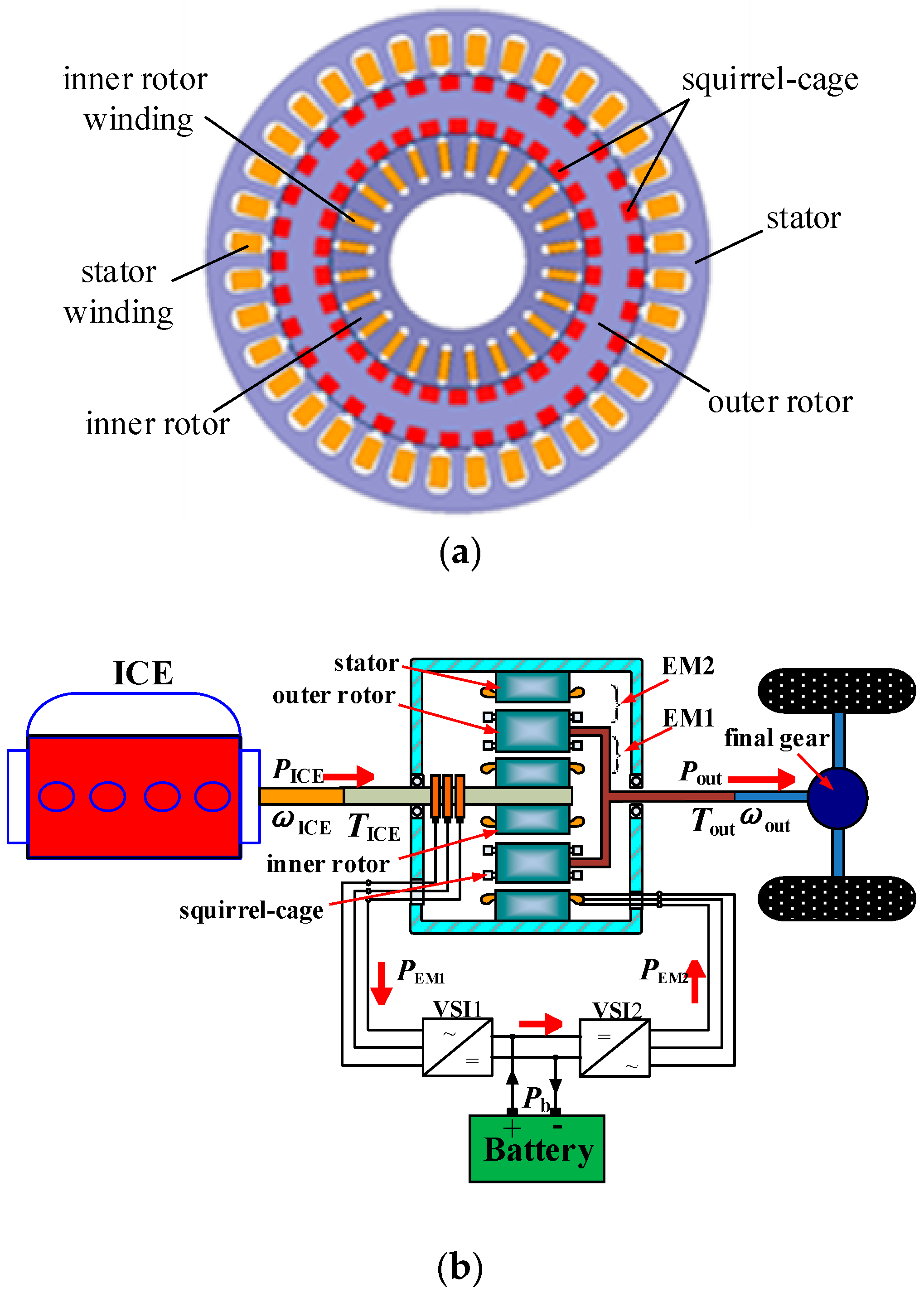
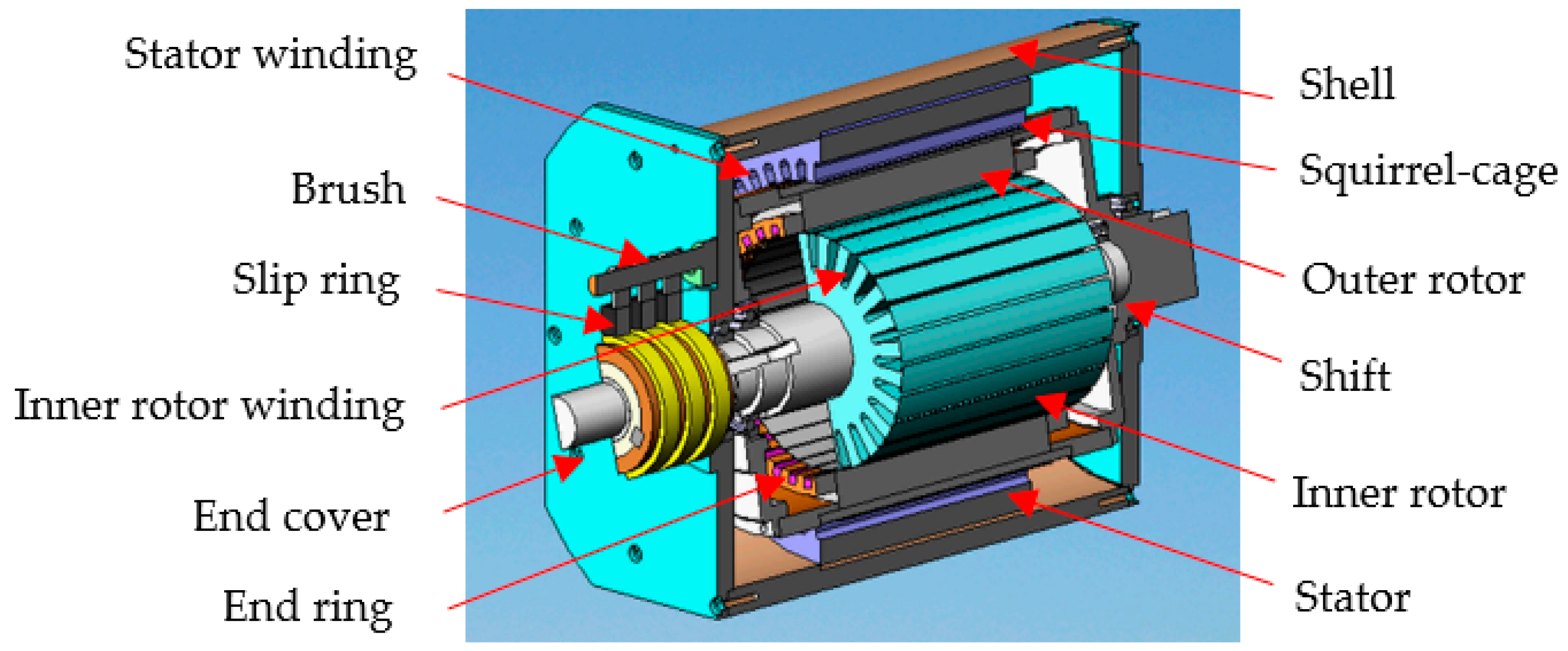
2. Configuration and Working Principle
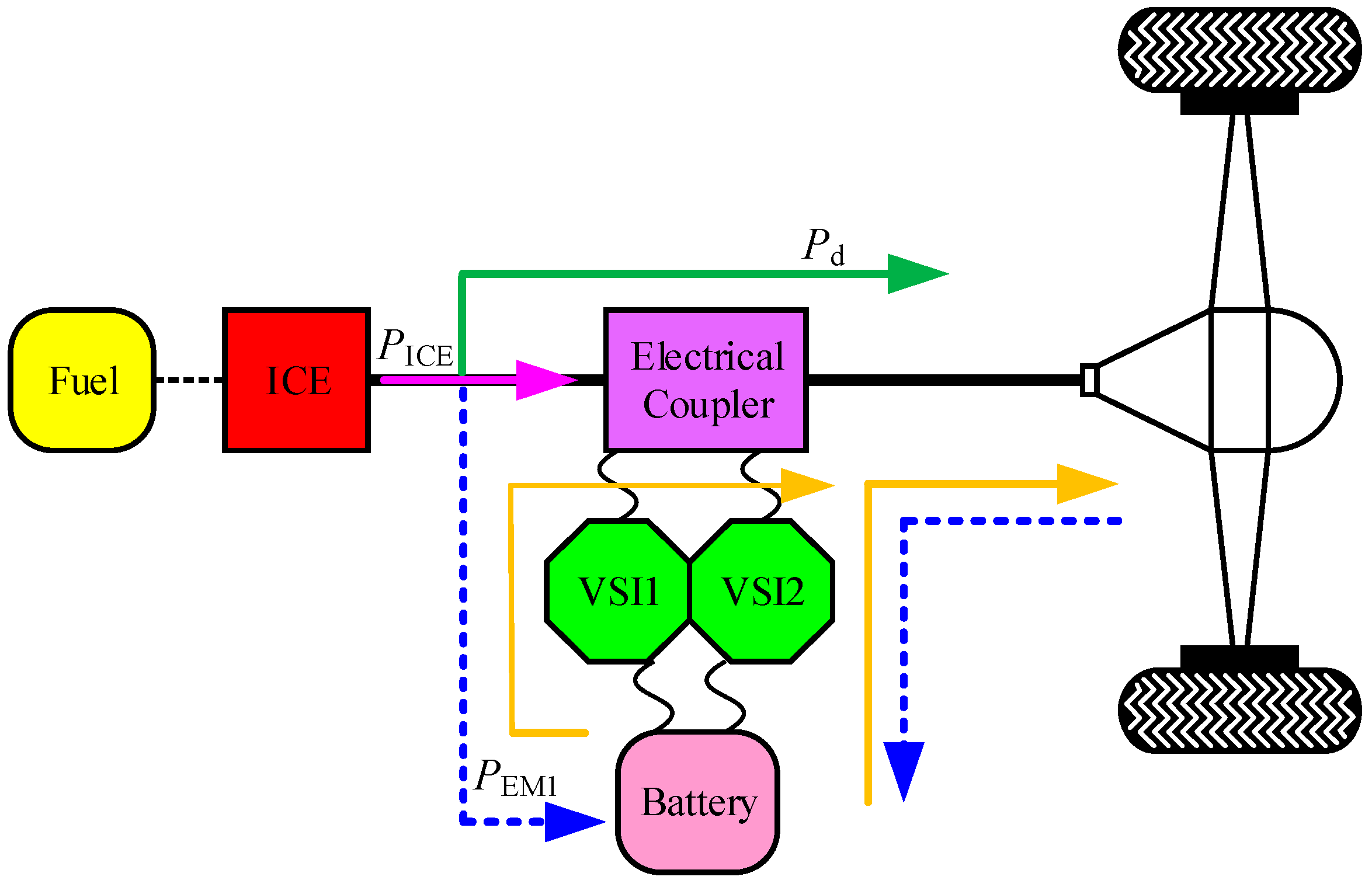
2.1. Configuration
2.2. Working Principle
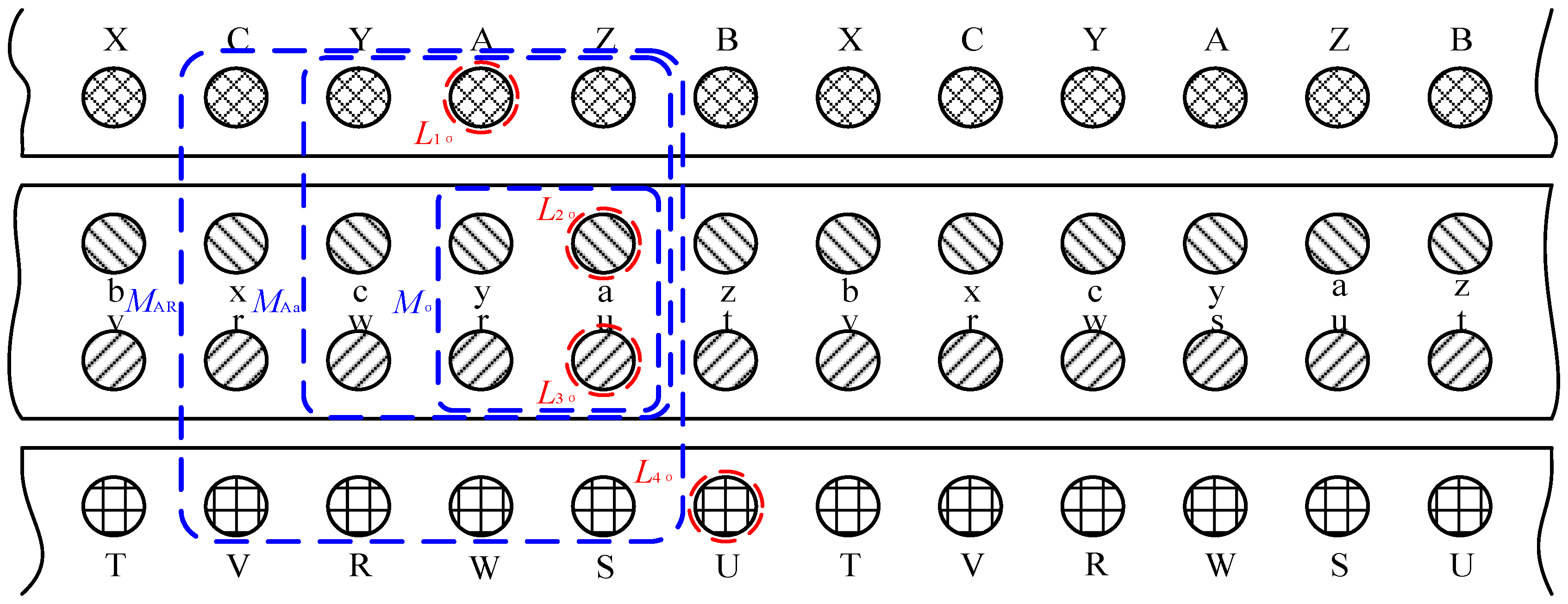
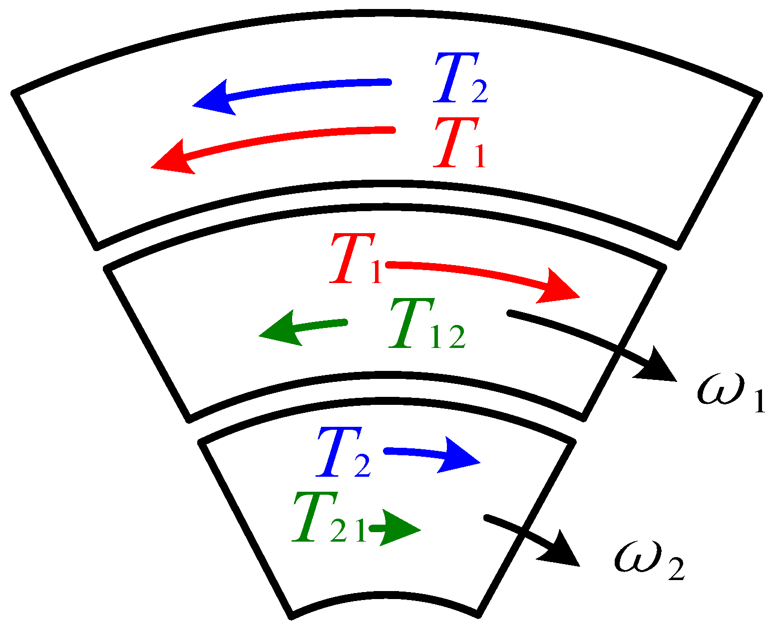
3. Torque Mathematical Model of EVT in ABC Three-Phase Coordinate System
4. Optimal Design
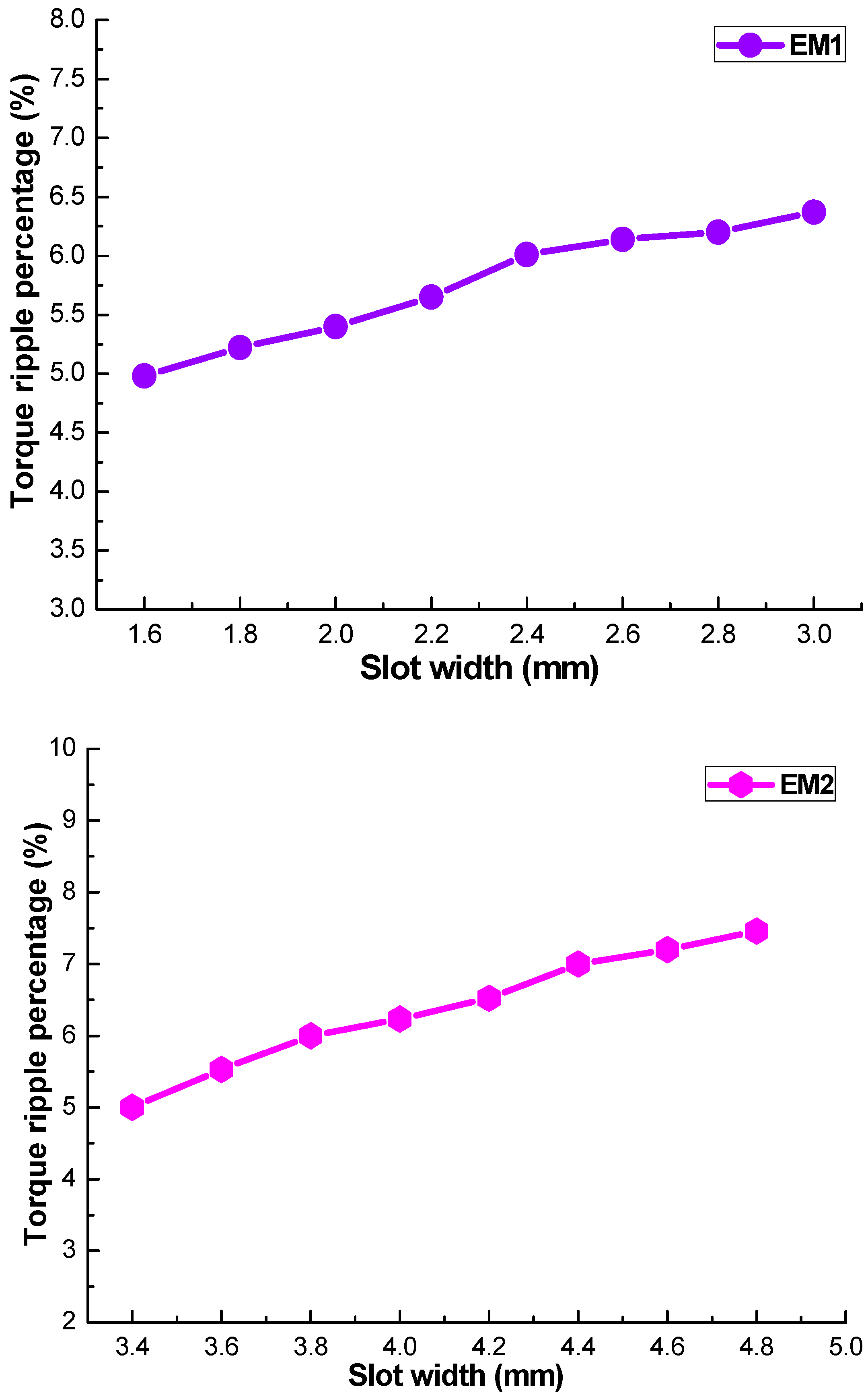
4.1. Slot Width
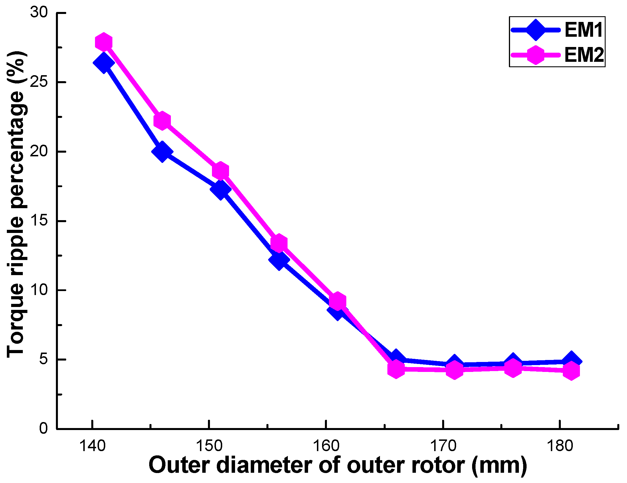
4.2. Outer Rotor Outer Diameter
4.3. Stator Outer Diameter
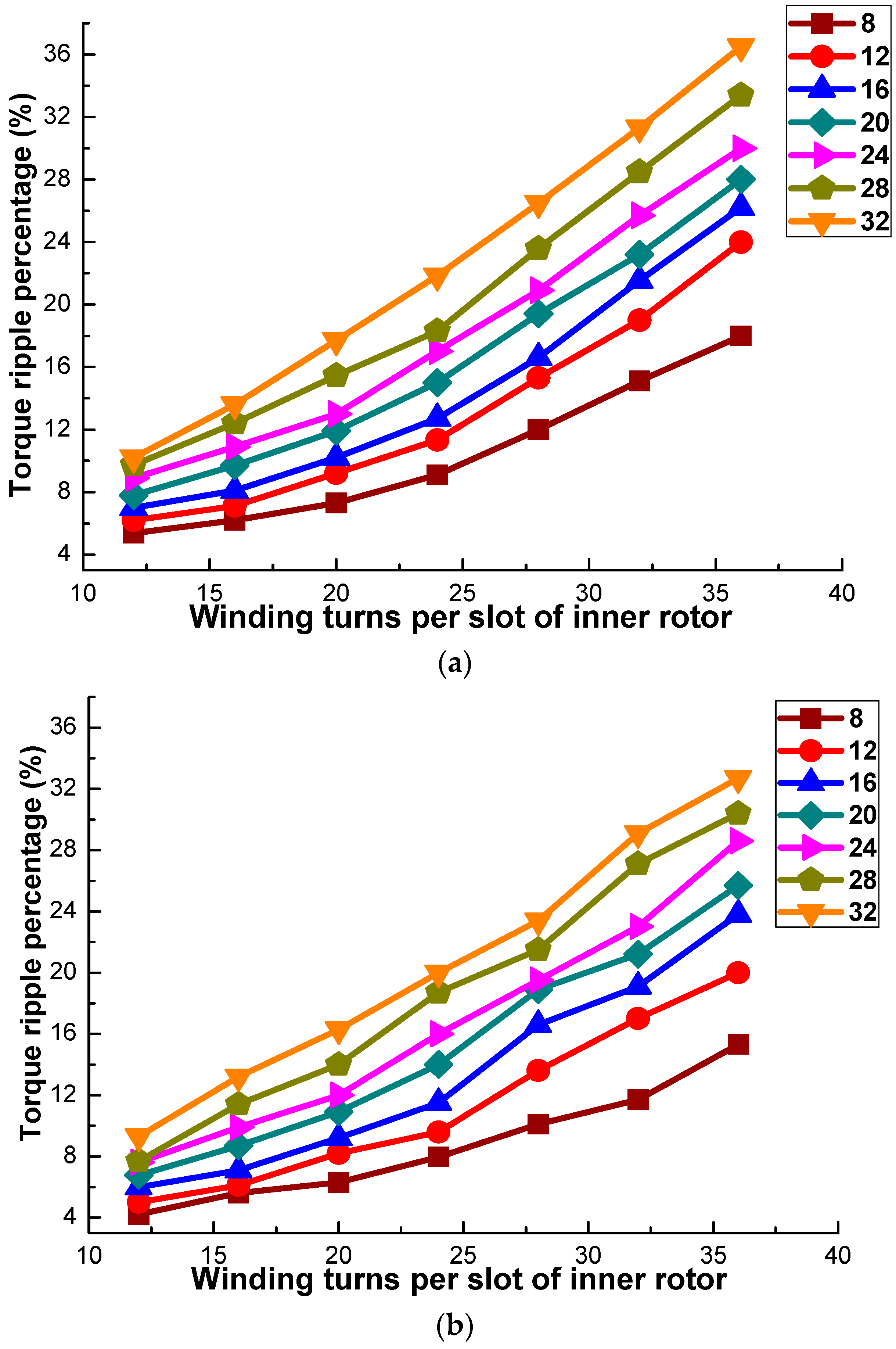
4.4. Winding Turns per Slot
4.5. Excitation Current with Different Amplitude and Initial Phase Angle
- (1)
- A smaller slot width of stator and inner rotor is expected. However, the slot width of the machine should be a little larger to facilitate coil processing. Generally speaking, the slot width is at least three multiples of the wire diameter. As we choose the wire diameter of inner rotor and stator is 0.65 mm and 1.3 mm, the slot width of EM1 and EM1 is identified as 2 mm and the 4 mm, separately;
- (2)
- A larger outer diameter of outer rotor and stator is desirable considering torque ripple, but the torque ripple gradually becomes steady when the size increases to a certain degree. For reducing the size of EVT and convenience for installing in HEVs, the outer diameter of the outer rotor is selected as 166 mm, and the yoke thickness of the outer rotor is 14 mm. The outer diameter of the stator is determined as 223 mm, and its yoke thickness is 14.5 mm;
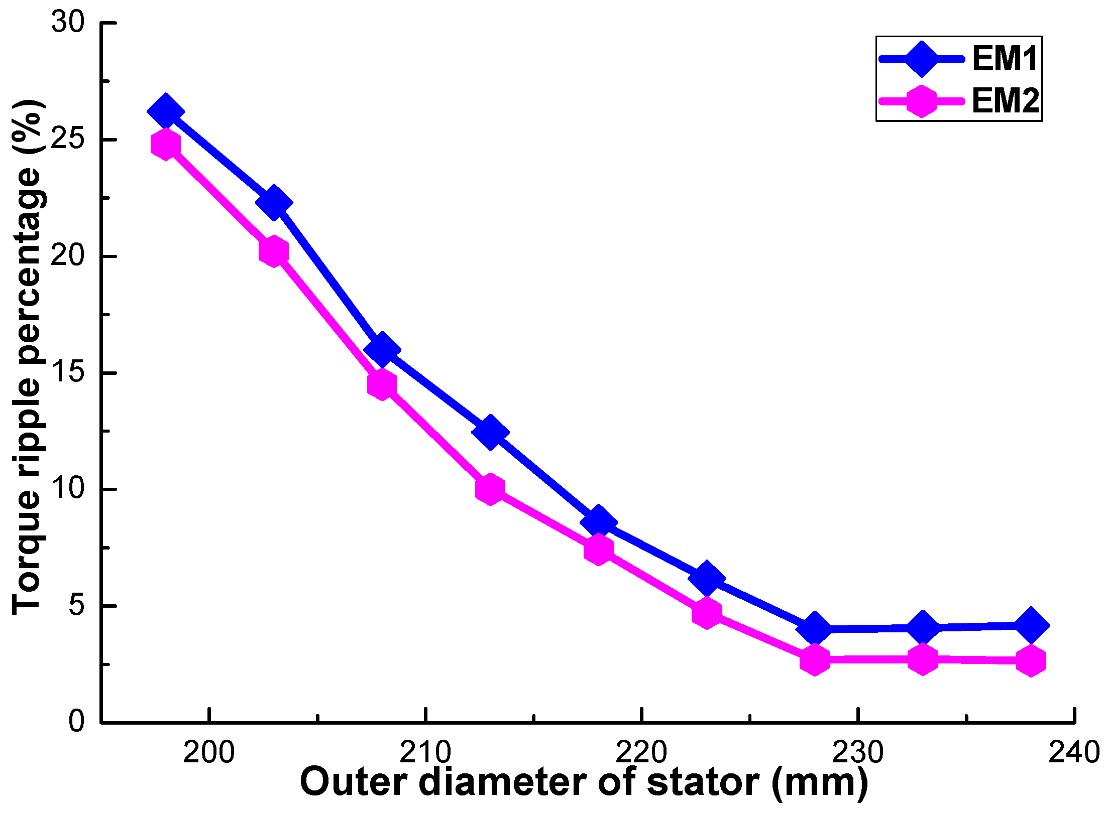
- (3)
- Fewer winding turns are required to reduce the torque ripple. However, with fewer winding turns, the excitation reactance is smaller, which will increase the excitation current. In order to make the machine need a smaller excitation current, the winding turns per slot in the inner rotor and stator are set at 16 and 8, respectively;
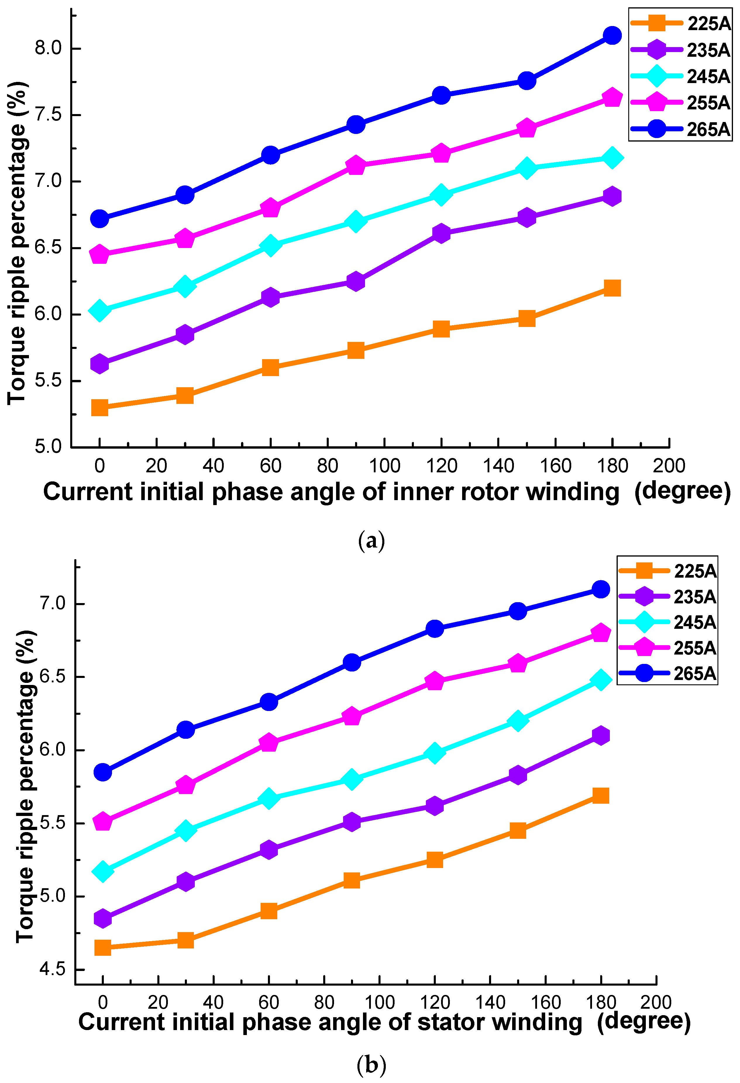
- (4)
- A smaller excitation current amplitude and initial phase angle can reduce the torque ripple. In this optimal design, the excitation current amplitude of EM1 is chosen as 30 A, and initial phase angle is 0 degrees. For EM2, the excitation current amplitude is 90 A, and the initial phase angle also chosen as 0 degrees.
5. Performance Validation
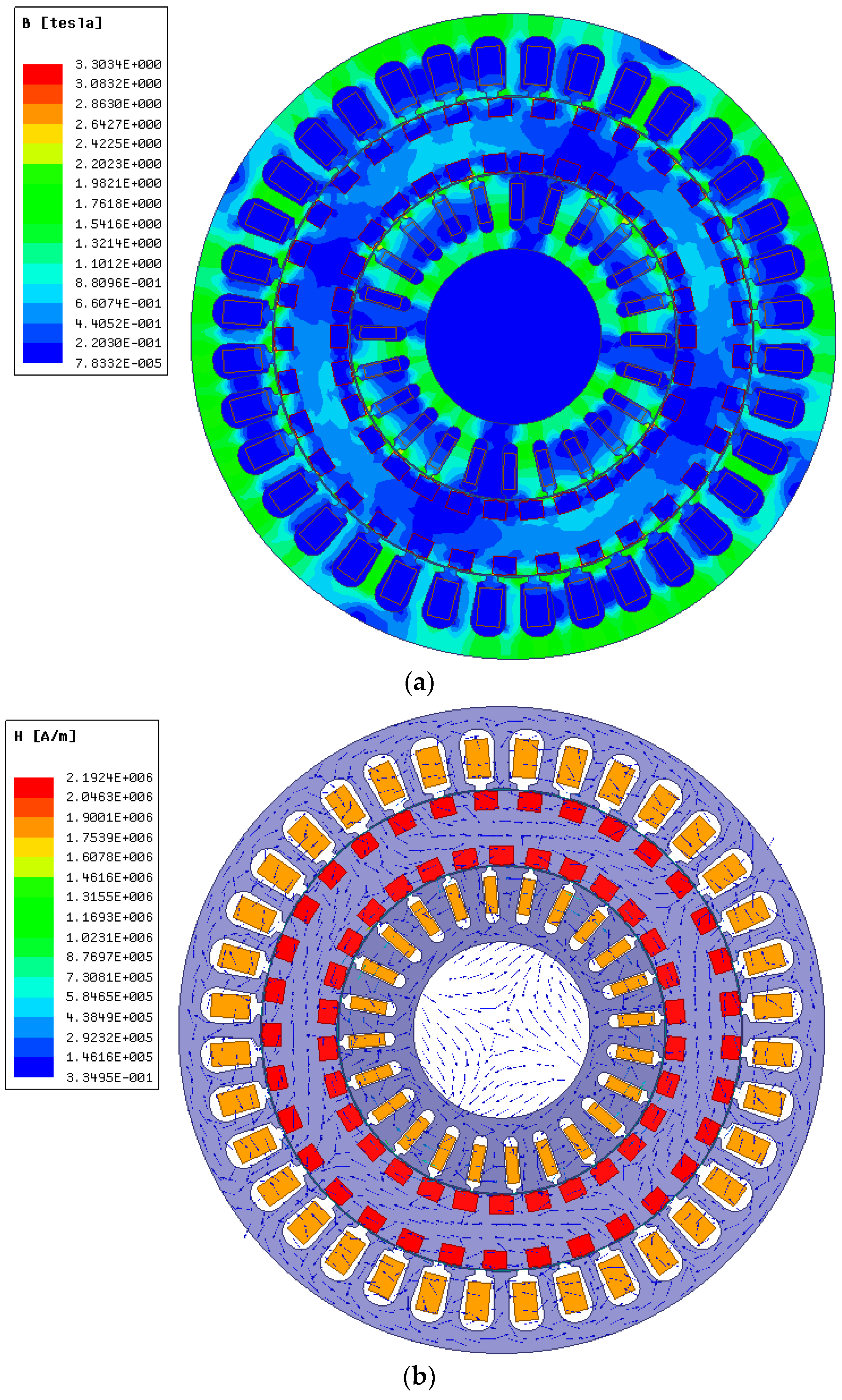
5.1. Field Distribution
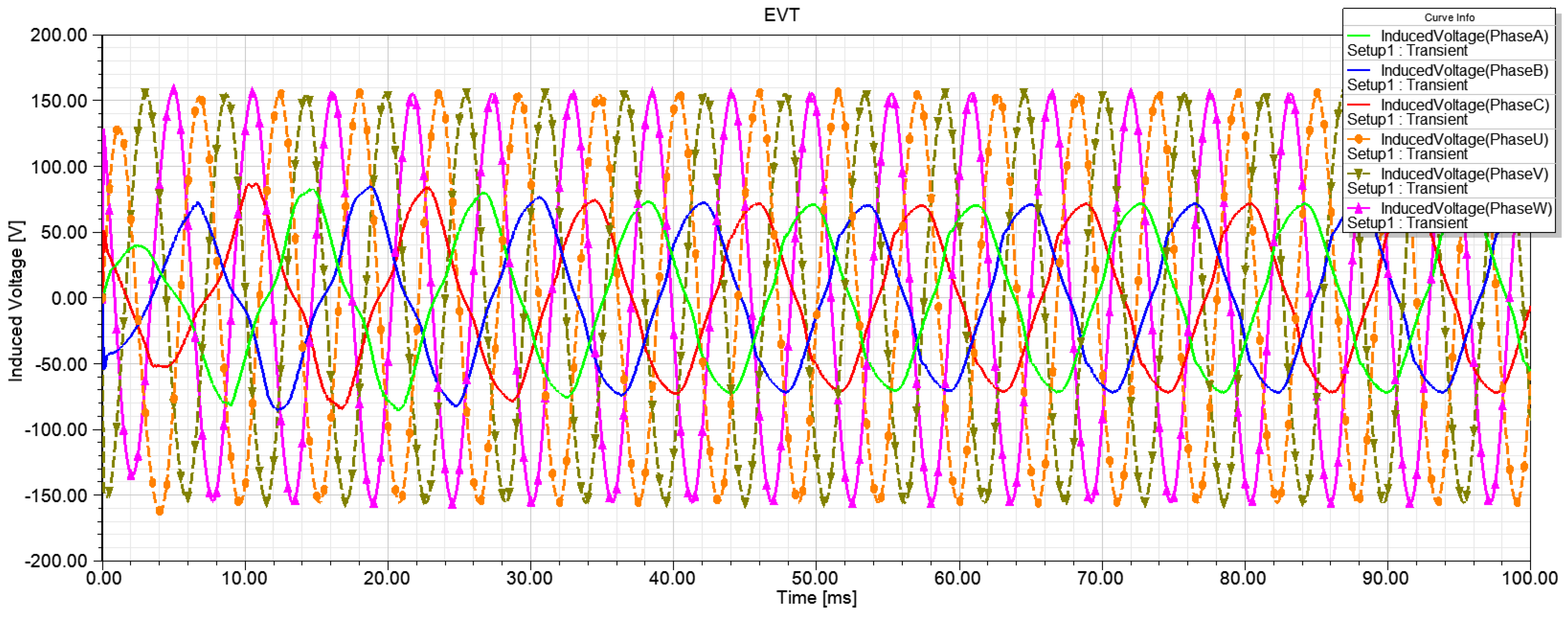
5.2. Induced Voltage at Full-Load Operation
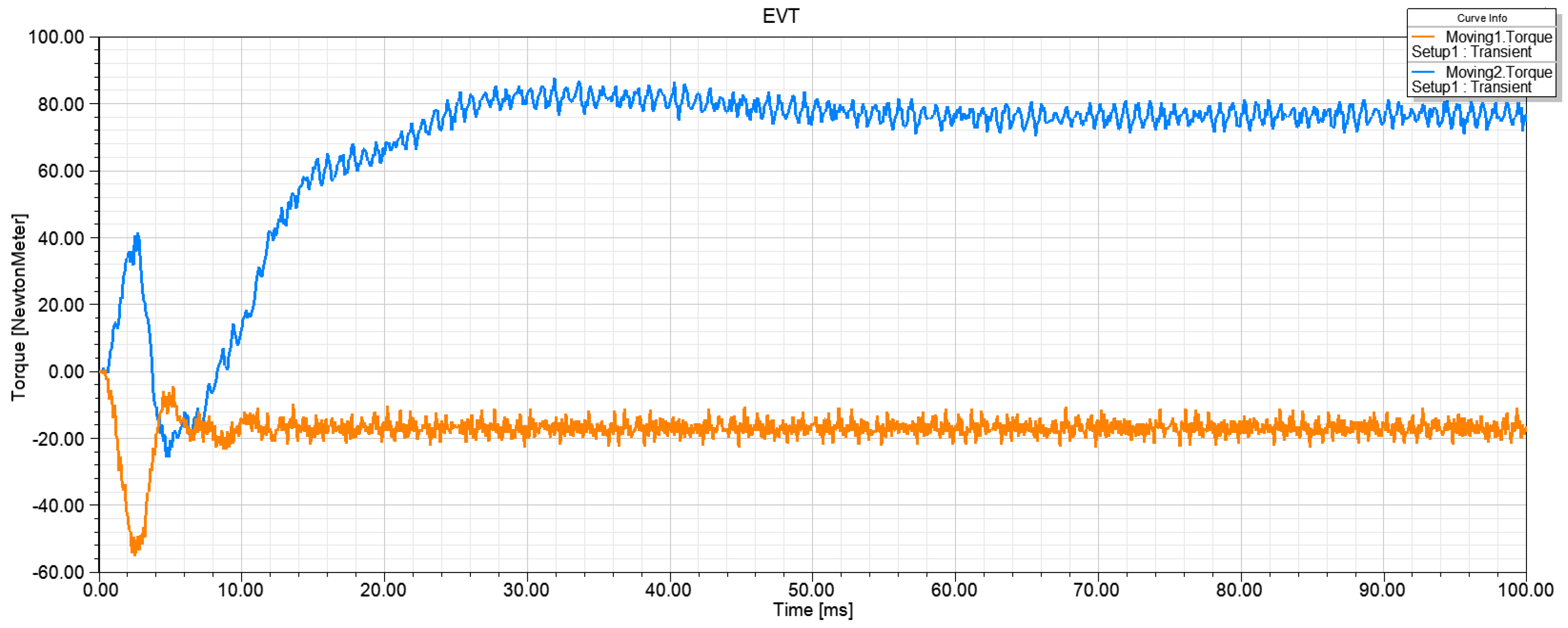
5.3. Output Torque at Full-Load Operation
6. Conclusions
Author Contributions
Funding
Conflicts of Interest
References
- Vinot, E.; Reinbold, V.; Trigui, R. Global Optimized Design of an Electric Variable Transmission for HEVs. IEEE Trans. Veh. Technol. 2016, 65, 6794–6798. [Google Scholar] [CrossRef]
- Xu, Q.W.; Cui, S.M.; Song, L.W.; Zhang, Q.F. Research on the power management strategy of hybrid electric vehicles based on electric variable transmissions. Energies 2014, 7, 934–960. [Google Scholar] [CrossRef]
- Su, P.; Hua, W.; Zhang, G.; Chen, Z.; Cheng, M. Analysis and evaluation of novel rotor permanent magnet flux-switching machine for EV and HEV applications. IET Electr. Power Appl. 2017, 11, 1610–1618. [Google Scholar] [CrossRef]
- Arunkumar, J.; Andrew, C.; Tek, T.L. Review of prospects for adoption of fuel cell electric vehicles in New Zealand. IET Electr. Syst. Trans. 2017, 7, 259–266. [Google Scholar]
- Hoeijmakeer, M.J.; Ferreira, J.A. The electric variable transmission. IEEE Trans. Ind. Appl. 2006, 42, 1092–1100. [Google Scholar] [CrossRef]
- Xu, Q.W.; Sun, J.; Luo, L.Y.; Cui, S.M.; Zhang, Q.F. A Study on Magnetic Decoupling of Compound-Structure Permanent-Magnet Motor for HEVs Application. Energies 2016, 9, 819. [Google Scholar] [CrossRef]
- Sinervo, A.; Arkkio, A. Rotor radial position control and its effect on the total efficiency of a bearingless induction motor with a cage rotor. IEEE Trans. Magn. 2014, 50, 1–9. [Google Scholar] [CrossRef]
- Cai, H.W.; Xu, L.Y. Modeling and Control for Cage Rotor Dual Mechanical Port Electric Machine–Part I: Model Development. IEEE Trans. Energy Convers. 2015, 30, 957–965. [Google Scholar] [CrossRef]
- Osman, C.S.; Alper, T.; Lale, T.E. Efficiency analysis in three phase squirrel cage induction motor. In Proceedings of the 2016 National Conference on Electrical, Electronics and Biomedical Engineering (ELECO), Bursa, Turkey, 1–3 December 2016; pp. 334–338. [Google Scholar]
- Yang, Y.Y.; Schofield, N.; Emadi, A. Integrated Electromechanical Double-Rotor Compound Hybrid Transmissions for Hybrid Electric Vehicles. IEEE Trans. Veh. Technol. 2016, 65, 4687–4699. [Google Scholar] [CrossRef]
- Kim, J.; Kim, T.; Min, B.; Hwang, S.; Kim, H. Mode Control Strategy for a Two-Mode Hybrid Electric Vehicle Using Electrically Variable Transmission (EVT) and Fixed-Gear Mode. IEEE Trans. Veh. Technol. 2011, 60, 793–803. [Google Scholar] [CrossRef]
- Liu, Y.L.; Niu, S.X.; Ho, S.L.; Fu, W.N. A New Hybrid-Excited Electric Continuous Variable Transmission System. IEEE Trans. Magn. 2014, 50, 8104104. [Google Scholar] [CrossRef]
- Shane, O.; Sumedha, R. A Combined High-Efficiency Region Controller to Improve Fuel Consumption of Power-Split HEVs. IEEE Trans. Veh. Technol. 2016, 65, 4597–4607. [Google Scholar]
- Ma, Z.T.; Cui, S.M.; Li, S.P. Applying dynamic programming to HEV powertrain based on EVT. In Proceedings of the 2015 International Conference on Control, Automation and Information Sciences (ICCAIS), Changshu, China, 29–31 October 2015. [Google Scholar]
- Liu, Y.L.; Niu, S.X.; Fu, W.N. Design of an Electrical Continuously Variable Transmission Based Wind Energy Conversion System. IEEE Trans. Ind. Electron. 2016, 63, 6745–6755. [Google Scholar] [CrossRef]


| Power Relationship | Speed Relationship | EM1 | EM2 | Battery |
|---|---|---|---|---|
| PICE_out = PLoad | ωICE > ωEM2 | generation operation | electric operation | stop operation |
| ωICE = ωEM2 | ICE direct-driven mode | |||
| ωICE < ωEM2 | electric operation | generation operation | ||
| PICE_out < PLoad | - | generation operation | electric operation | operation |
| PICE_out > PLoad | - | generation operation | electric operation | operation and charged by EM1 |
| Design Parameters | EM1 | EM2 |
|---|---|---|
| Rated power (kW) | 15 | 30 |
| Rated current (A) | 225 | 225 |
| Rated speed (rpm) | 5000 | 2400 |
| Number of phase | 3 | 3 |
| Iron core material | DW310-35 | DW310-35 |
| Squirrel-cage material | red copper | red copper |
| Number of slot | 24 | 36 |
| Number of squirrel-cage | 30 | 33 |
| Iron core length (mm) | 90 | 90 |
| Air-gap length (mm) | 0.5 | 0.5 |
| Slot width (mm) | 2 | 4 |
| Squirrel-cage width (mm) | 8 | 8 |
| Squirrel-cage thickness (mm) | 6 | 6 |
| Inner diameter of inner rotor (mm) | 61 | |
| Outer diameter of inner rotor (mm) | 113 | |
| Inner diameter of outer rotor (mm) | 114 | |
| Outer diameter of outer rotor (mm) | 166 | |
| Inner diameter of stator (mm) | 167 | |
| Outer diameter of stator (mm) | 223 | |
© 2018 by the authors. Licensee MDPI, Basel, Switzerland. This article is an open access article distributed under the terms and conditions of the Creative Commons Attribution (CC BY) license (http://creativecommons.org/licenses/by/4.0/).
Share and Cite
Xu, Q.; Sun, J.; Wang, W.; Mao, Y.; Cui, S. Design Optimization of an Electric Variable Transmission for Hybrid Electric Vehicles. Energies 2018, 11, 1118. https://doi.org/10.3390/en11051118
Xu Q, Sun J, Wang W, Mao Y, Cui S. Design Optimization of an Electric Variable Transmission for Hybrid Electric Vehicles. Energies. 2018; 11(5):1118. https://doi.org/10.3390/en11051118
Chicago/Turabian StyleXu, Qiwei, Jing Sun, Wenjuan Wang, Yunqi Mao, and Shumei Cui. 2018. "Design Optimization of an Electric Variable Transmission for Hybrid Electric Vehicles" Energies 11, no. 5: 1118. https://doi.org/10.3390/en11051118
APA StyleXu, Q., Sun, J., Wang, W., Mao, Y., & Cui, S. (2018). Design Optimization of an Electric Variable Transmission for Hybrid Electric Vehicles. Energies, 11(5), 1118. https://doi.org/10.3390/en11051118