1. Introduction
Fossil fuels, which have been used as resources for electricity generation for centuries, are reaching their limits. In addition, the problems caused by the use of fossil fuels such as global warming and air pollution are global growing interests. As with the Paris climate agreement, a low carbon slogan was created around the world and reflected in the energy policies of each country [
1,
2]. The focus shifted to distributed generation (DG) system using renewable energy resource (RES) such as photovoltaic and wind power instead of the fossil fuels. However, from the viewpoint of power operation, there is a limit to continuously supplying stable power. Therefore, the energy storage system (ESS) is needed to improve the limits. In particular, the battery-based ESS is usually used [
3,
4,
5,
6]. There are a lot of studies carried out to store energy into battery efficiently [
7,
8,
9]. The ESS in a DG system based on RES plays various roles [
10,
11]. For example, maximum power point tracking, main grid protection, high-quality power supply, frequency regulation, load leveling, and peak shaving [
12,
13,
14]. Furthermore, it is required to replace the role of uninterruptible power supply (UPS) as well as the role of existing diesel emergency generator in DG system. The power conditioning system (PCS) is indispensably required for the ESS to perform these various roles. In this paper, the smart PCS for UPS operation in ESS in DG system was proposed.
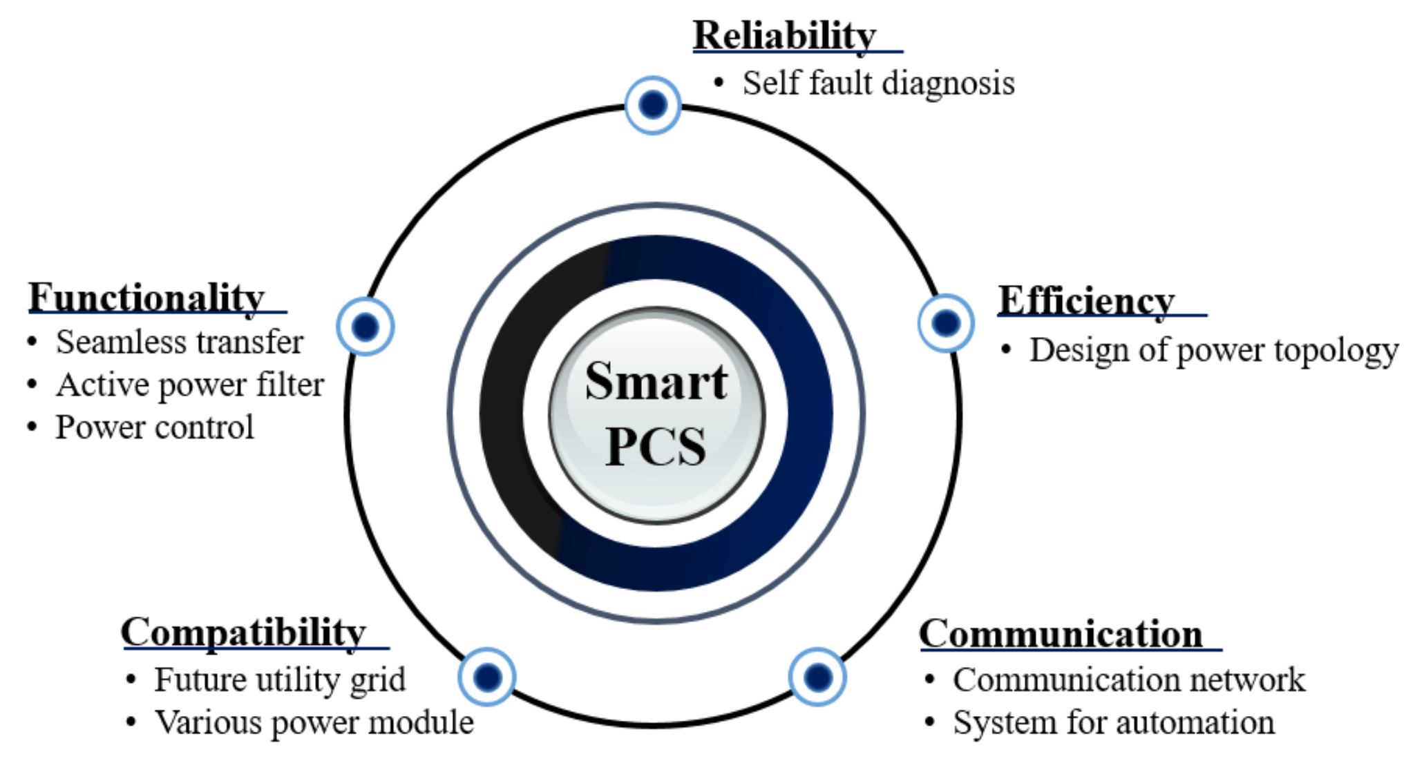
Figure 1 shows a variety of features that smart PCS may have. Reliability such as self-diagnosis, and high efficiency. Furthermore, communication functions and compatibility issues are considered to be used in conjunction with various systems. The seamless transfer function was focused that enables the PCS to supply power to the load stably, not only in normal grid but also in abnormal grid conditions in this paper. Under normal grid condition, the PCS charges and discharges the ESS, and depending on the load or grid states, control the grid current. When a non-linear load is connected, the inverter supplies a sinusoidal current to the load through by using the active power filter control [
15,
16,
17]. In the event of a system fault such as a power failure, the PCS should accurately recognize the grid conditions and supply a stable voltage to the load. In other words, the PCS should be capable of bi-modal operation to enable grid-connected (GC) and stand-alone (SA) operations. Sudden changes in the operating mode cause unwanted phenomena (e.g., voltage/current spikes and inrush currents). These may cause system or load performance to be degraded or cause failure. However, since the critical load must be supplied with power stably even in transient condition, the PCS should minimize unwanted phenomena. A key function for the smooth transition is seamless transfer control.
Several researches on seamless transfer strategies have been carried out [
18,
19,
20,
21,
22]. Indirect current method-based seamless transfer control was examined [
18,
19]. This method, however, requires a long clearing time to change the operation mode. When a grid fault occurs, the operation mode is changed to autonomous via limiters, however, the load voltage during SA mode is maintained the maximum level of the normal state. Therefore, it is likely to shift to an over voltage condition. In addition, it is difficult to apply it in an actual field because load current information is required [
20,
21]. In [
22], it explained the seamless transfer function with a feedforward voltage control in over voltage or swell condition. Although the system explains the seamless transfer operation under the over voltage or swell condition, it has a lack of measures for other grid conditions. Currently, the algorithms that are investigated focus on the seamless transfer strategy itself, and there are no results that satisfy various load conditions such as light, rated, nonlinear, non-detection zone (NDZ) load conditions are not considered at the same time. When a non-linear load is connected, the load must be provided with a high quality voltage through harmonic compensation control via the proportional resonant (PR) controller [
23] or repetitive controller (RC) [
24,
25].
In this paper, the operation mode change from GC to SA was considered in the seamless transfer function. It is also necessary to recover from SA to GC, however, there is sufficient time for the PCS to switch modes after the grid is restored normally, and it can be intentionally manipulated if certain conditions (i.e., voltage magnitude and frequency) are met. On the other hand, mode switching from GC to SA operation is caused by unintentional grid abnormality. The proposed parts are as follows.
the PCS can transfer from grid-connected mode to stand-alone mode within 1/4 cycle without measuring the load current under various load conditions.
harmonic compensation algorithm in independent operation can supply high quality voltage to the load.
can avoid the NDZ condition in which the PCS cannot detect the present operation mode.
When the difference between the power consumption of the load and the power supplied by the PCS is small, the PCS cannot accurately recognize the grid state (i.e., NDZ condition). In this case, a control algorithm is required to escape this range because it cannot transmit the information to the ESS despite the occurrence of a system anomaly, which can cause secondary accidents in the system operation [
26,
27,
28]. Therefore, experiments were conducted for each case that can occur depending on the load conditions, and the validity of the above-mentioned control algorithm was verified.
The rest of this paper is organized as follows. The smart PCS with an UPS function is introduced in
Section 2.
Section 3 describes the proposed control algorithm applied to the smart PCS in detail. The experimental results based on the proposed algorithm are presented in
Section 4. Finally,
Section 5 summarizes the results of this paper.
2. Smart PCS with UPS Function Description
The PCS based on the RES is evolving smarter in such a way that it recognizes the local conditions, such as voltage and frequency, and detects an accident or autonomously controls active and reactive power. Several major functions of the PCS have been introduced [
29].
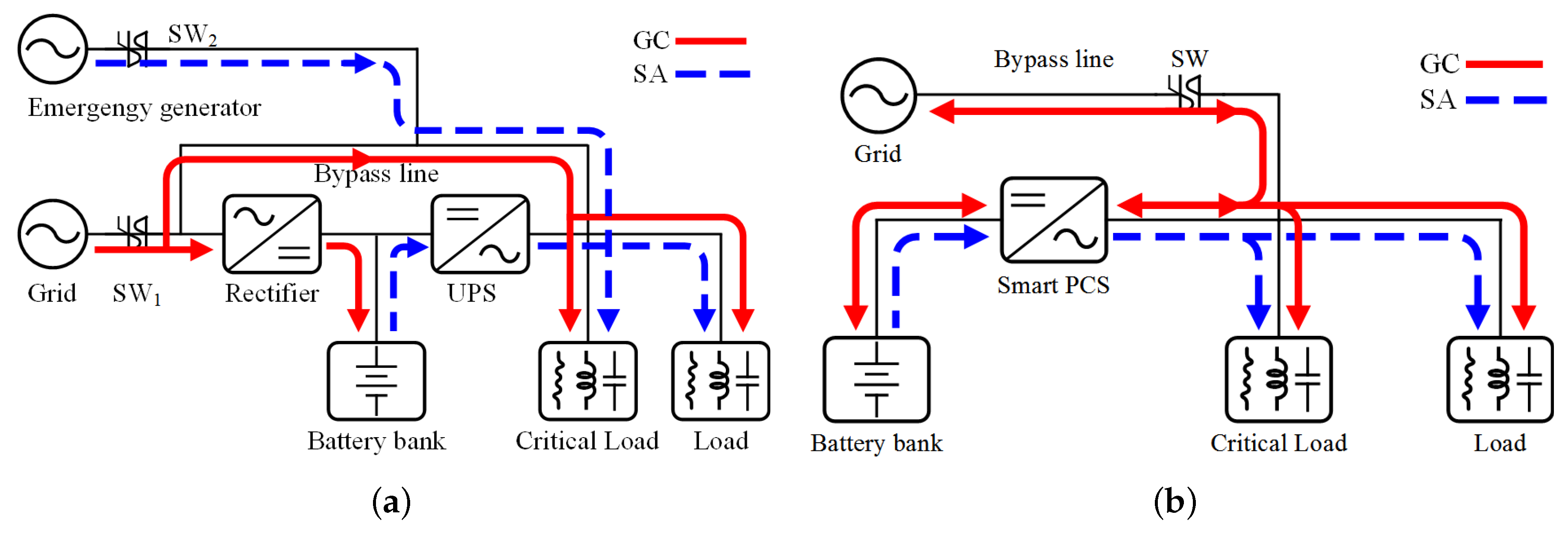
Figure 2a shows a conventional operation block diagram of the UPS system for emergency power generation. Under the normal grid condition (i.e., SW
closed and SW
opened), the load is provided the power from the grid directly through the bypass line and the rectifier charges the battery bank. When an abnormal grid condition occurs, SW
is opened and the emergency generator operates. If the emergency generator operates, SW
is closed and the emergency generator supplies power to the load. The load, however, temporarily cannot be provided the power during the emergency generator reaches a steady state. Therefore, in the case of a critical load, the power is supplied continuously using other equipment (i.e., UPS).
Figure 2b presents a proposed smart PCS block diagram. SW is closed during the normal grid state. The load is supplied power through the bypass line and the smart PCS controls the grid current by charging/discharging the battery bank. When an abnormal grid state occurs, the load is powered through the PCS. Furthermore, the power can be provided reliably from the smart PCS without additional UPS equipment even if the critical load is connected. In general, the UPS needs to meet 35% of the normal voltage rate within 4 ms [
29]. When a non-linear load is connected during SA operation, the load voltage is distorted; hence, the quality is degraded. At this time, the voltage harmonic compensation function enables the total harmonic distortion (THD) of a load voltage less than 5% to satisfy the [
30]. Moreover, the PCS cannot operate correctly under the NDZ condition. Therefore, a recognizing and escaping algorithm is also required. The smart PCS proposed in this paper can meet the above UPS regulation under a range of load conditions and it can supply stable power continuously to the loads.
3. Proposed Algorithm of the Smart Power Conditioning System
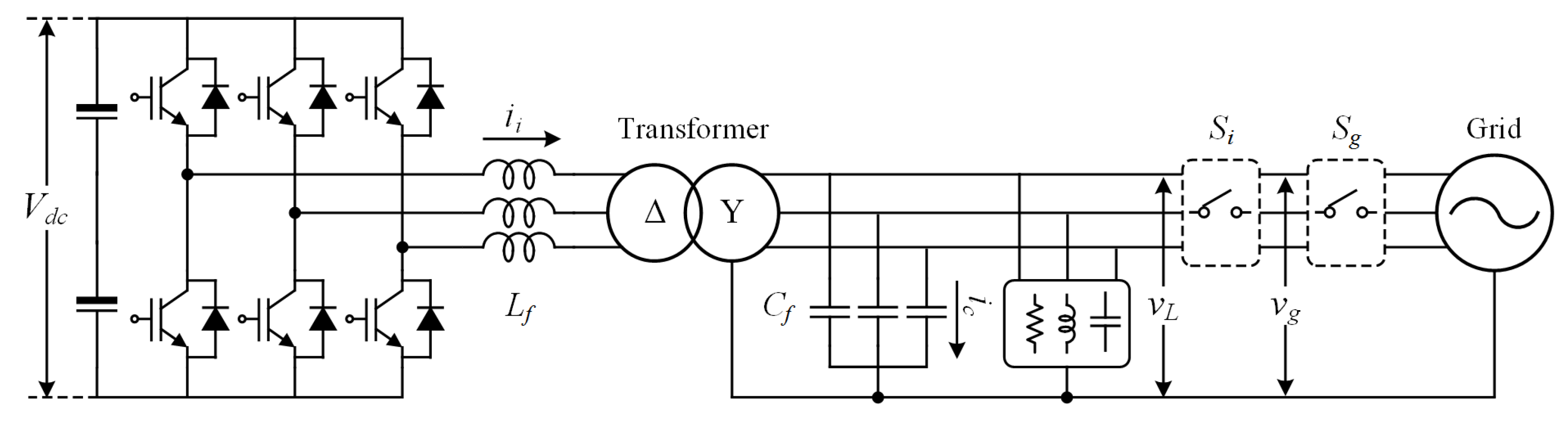
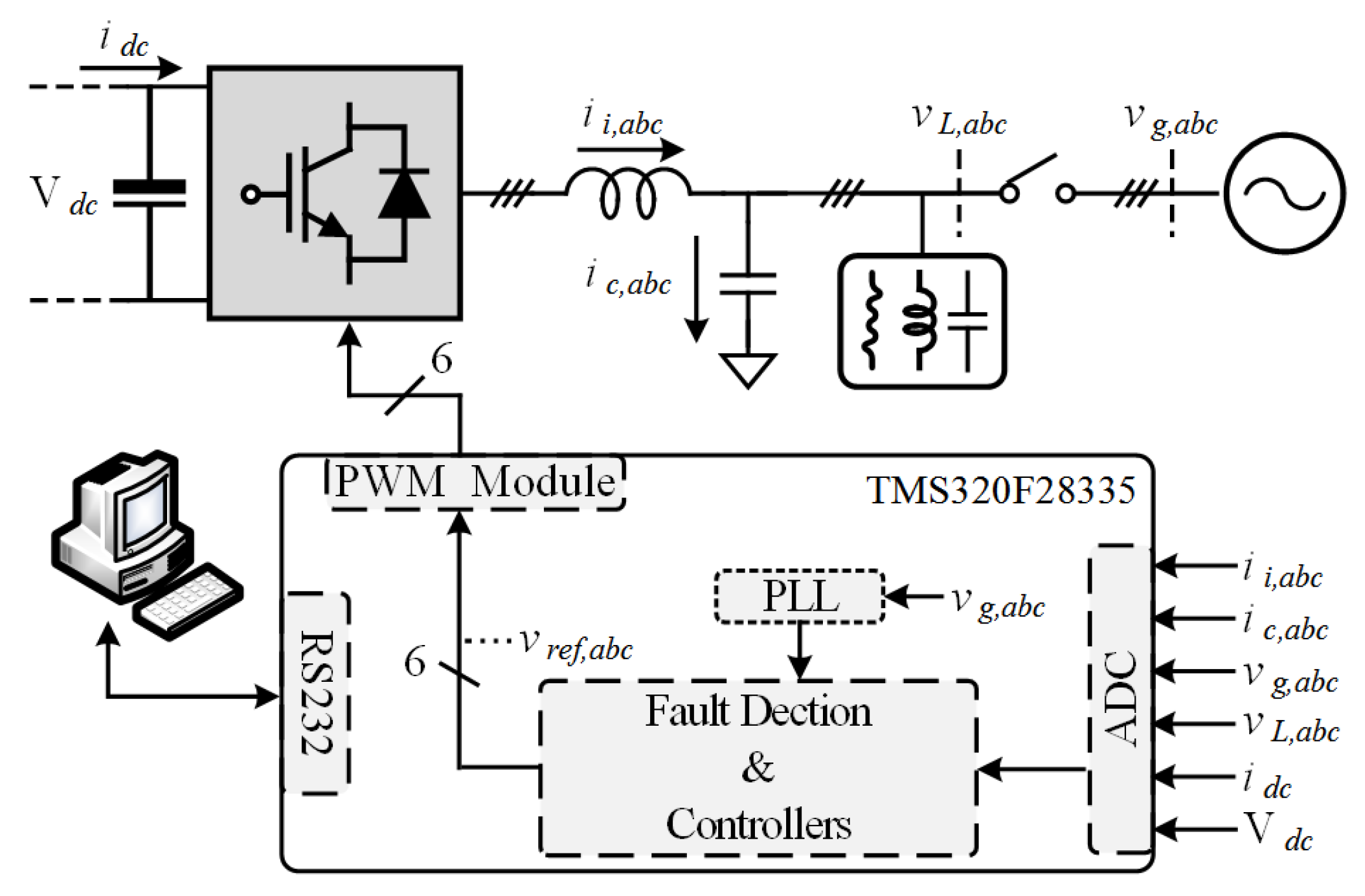
Figure 3 shows a three-phase PCS topology. The topology is composed of a DC link capacitor, IGBTs, a filter inductor (
) and capacitor (
), a step-up transformer, a load that consists of linear or non-linear, and switches. The load is connected to the filter capacitor in parallel. A switch
is used to connect/disconnect the grid line according to the PCS signal, and a switch
generates the grid fault condition on purpose. A DC voltage power source is applied to make a dc-link voltage (
).
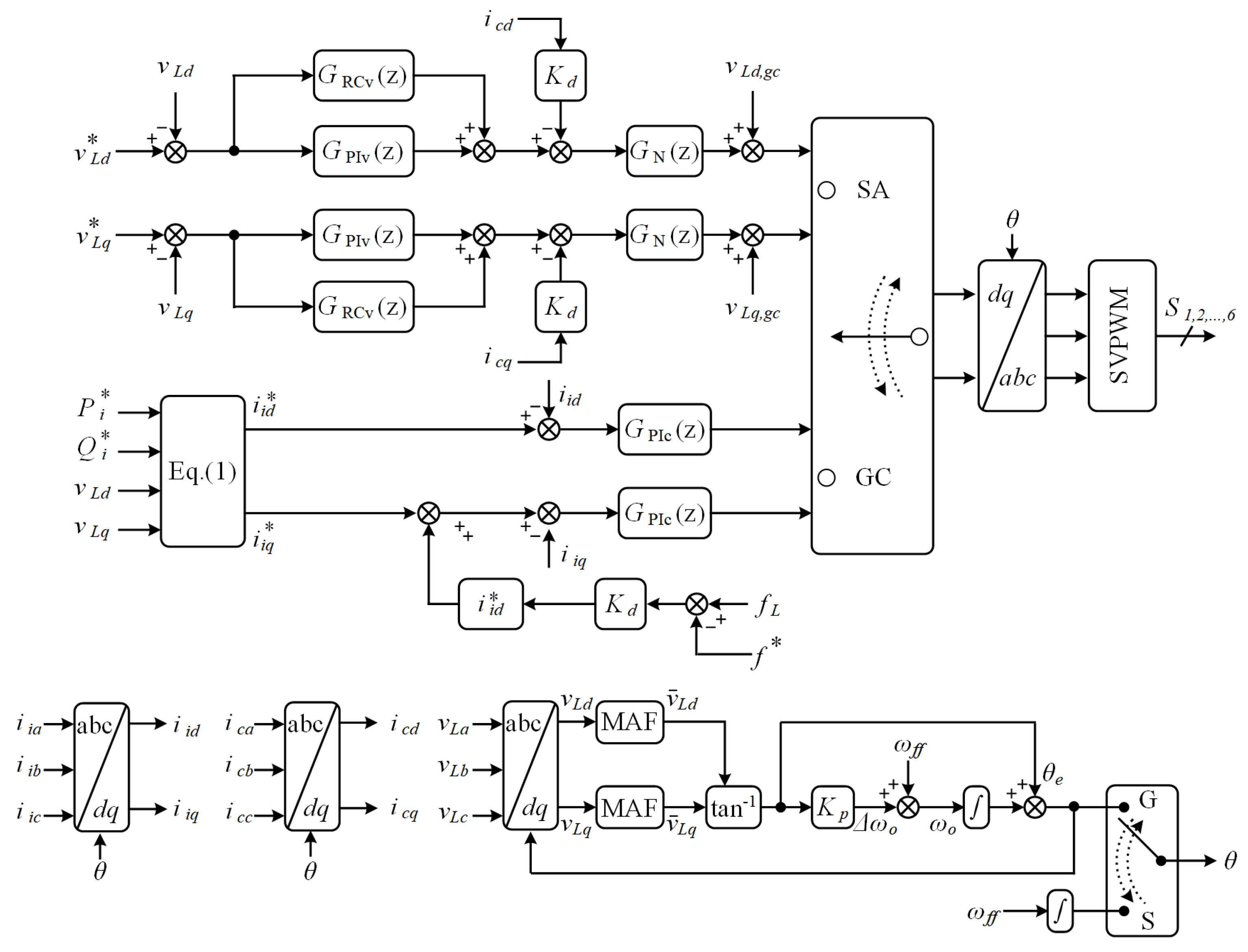
The proposed smart PCS control algorithm for the ESS is addressed in
Figure 4. The block diagram is composed of a phase-locked loop (PLL) part for phase detection and axis transformation, a part for converting the sensed 3-phase voltages and currents to the
-axis, current control part for GC mode, voltage control part for SA mode, an active damping part for inhibiting the resonance phenomenon of the system to improve the stability, and a part that can avoid the NDZ, which can occur under a specific load condition. The load voltage (
), the output current of the inverter (
), and capacitor current (
) are sensed. These three-phase components are transformed into
axis components by the Clarke and Park’s transformations. The load voltage (
), the inverter current (
),and the capacitor current (
) are the result of transformation respectively.
In normal grid condition (i.e., GC operation mode), the current control loop is used to control the grid current. The reference of the inverter current control is calculated by
where
,
are the active and reactive reference power of the PCS.
is the transfer function of the proportional-integral (PI) controller for current control in the
z-domain. The grid current is typically controlled by the GC current loop according to (
1). The frequency difference between the reference and load was added to the reactive reference current to make frequency variation. When the grid failure occurs, the load frequency reaches the set limit value [
31]. After that the PCS changes its operation mode from GC to SA.
In SA mode, the load is no longer dominated by the grid. Therefore, the PCS controls the load voltage to supply power. is the PI controller transfer function for voltage control and is the RC transfer function in the z-domain. The RC is applied to improve the load voltage quality by compensating for the load voltage harmonics. A space vector pulse width modulation (SVPWM) is used to reduce the switching harmonics. It makes less harmonics in switching frequency. is a notch filter transfer function in the z-doamin and is an active damping coefficient. The notch filter and capacitor current is used to suppress the resonance of the filter characteristic and improve the system stability. is a feedforward term of load voltage to reduce the voltage transient when mode changes.
For the purpose of executing these above functions, following important algorithms are necessary. Detailed descriptions are addressed following subsection.
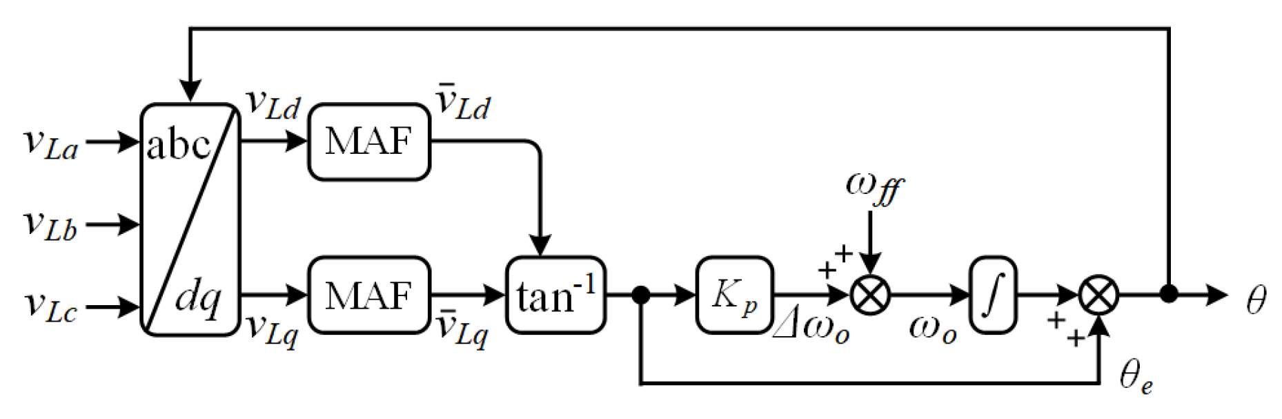
3.1. Phase-Locked Loop
The PLL plays important role in obtaining the unity power factor and controlling the frequency and phase. In general, the synchronous reference frame (SRF)-PLL is used because of the fast dynamic response. However, it is vulnerable to external disturbances, such as voltage distortion. Therefore, the SRF-PLL is not an appropriate algorithm for the proposed smart PCS. To enhance the robustness of the PLL, a moving average filter (MAF)-PLL is considered. The MAF is a type of linear-phase finite impulse response filter [
32] that can eliminate the harmonics at specific frequencies with high attenuation.
The block diagram of quasi-type1 (QT1)-PLL can be seen in
Figure 5.
and
are the filtered components by MAF,
Kp is a PLL coefficient, and
is a reference frequency. It has a robust feature and rapid dynamic response compared to the SRF-PLL and MAF-PLL [
33]. The frequency is obtained through the PLL using load voltage in this paper. When an grid accident occurs, the load frequency reaches the set frequency value [
31]. After that the PCS recognizes grid fault state and changes its operation mode. Therefore, the QT1-PLL is a suitable algorithm for the proposed smart PCS to detect the grid fault condition rapidly and is insensitive to a polluted grid condition. After the abnormal grid state occurs (i.e., stand-alone mode operation), a virtual PLL based on 60 Hz frequency is used to make a reference frequency.
3.2. Active Damping
When the PCS controls the load voltage, the resonance component that makes the system unstable occurs due to the characteristics of the
filter. Therefore, damping methods are needed to inhibit this occurrence [
34,
35,
36,
37]. The damping method can be classified into two types. Passive damping is a method of suppressing the resonance component by adding a damping resistor, which is advantageous because it can be implemented easily. On the other hand, the power loss problem can occur.
Hence, the active damping method was used in this paper. The active damping methods are divided mainly into two categories. One is a feedback-based method [
36] and the other is a filter-based method [
34,
35]. In general, the capacitor current feedback method is usually used. However, the system can be unstable when the resonant frequency is located around the low harmonic frequencies, despite using a capacitor current feedback method. Therefore, to improve the system stability, the proposed smart PCS uses two active damping methods (i.e., capacitor current feedback method and notch filter-based method) concurrently. The notch frequency was set as the
filter resonance frequency to suppress the influence of resonant.
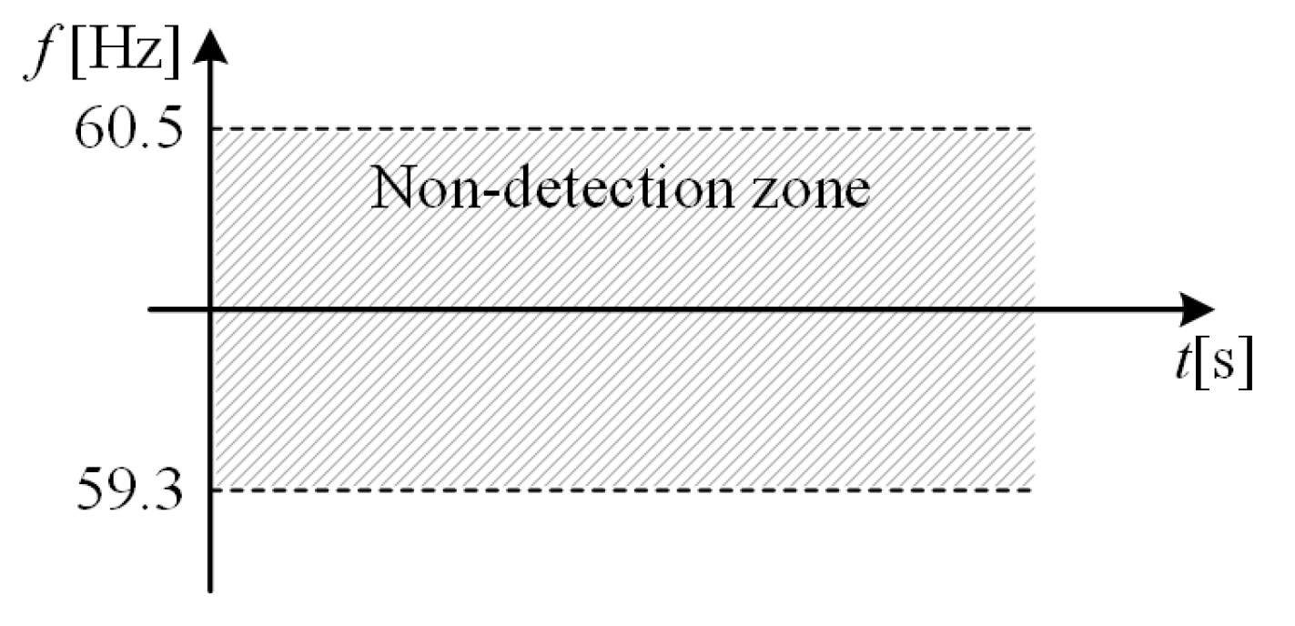
3.3. Non-Detection Zone
Figure 6 shows a NDZ frequency range of the PCS. From 60.5 Hz to 59.3 Hz is normal grid state frequency range according to the IEEE standard [
31]. When the grid faults occurs, the load frequency reaches its limit in normal load condition. However, the load is in NDZ condition, the load frequency does not reach the limit. It maintains the normal range. In this case, a control algorithm is required to escape this range because it cannot transmit the information to the ESS despite the occurrence of a system anomaly, which can cause secondary accidents in the system operation.
Active frequency drift with positive feedback method was adopted to detect and escape the non-detection range. The frequency difference between the reference and load was added to the reactive reference current to make frequency variation. In normal grid case (i.e., strong grid), the main grid controls the load voltage and frequency. The PCS cannot changes the load voltage and frequency easily. However, the grid outage occurs, the load condition cannot controlled by grid. Therefore, the PCS can check the load frequency variation by drifting the reactive current. After that, the load frequency moves to the upper or lower limit.
3.4. Controller Design
Assume that the DC voltage is stiff enough, therefore, the dynamic characteristic according to the DC voltage is not considered in this paper. The proposed controller consists of two controllers (i.e., current control for GC mode operation and voltage control for SA mode operation). Therefore, the analysis is required to ensure the stability of each controller.
3.4.1. Control in Grid-Connected Mode
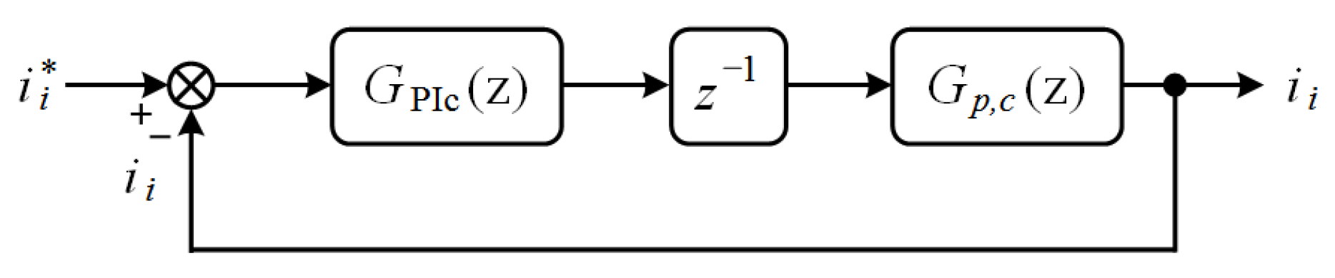
In the normal grid state, current control is performed by the PCS (i.e., GC operation mode).
Figure 7 presents a simplified block diagram of current control in the
z-domain.
is the PI controller transfer function discretized by the backward transformation which given by
where
is the proportional gain,
is the integral gain in current control.
is the sampling time,
is the computation delay, and the
is the transfer function of the current control plant discretized by zero order hold (ZOH) which is addressed by
To obtain the
, the magnitude of the transfer function is calculated and it can be approximated owing to the its unity characteristics at the crossover frequency,
(i.e.,
). Therefore,
is calculated by
The phase margin is determined by the
which is typically lower than the
. The
can be obtained with a desired phase margin.
The phase margin is also affected by
. Therefore, to minimize the effect of
, the integral time constant,
(i.e.,
), which makes controller design easy, is used [
38]. In general,
is selected by
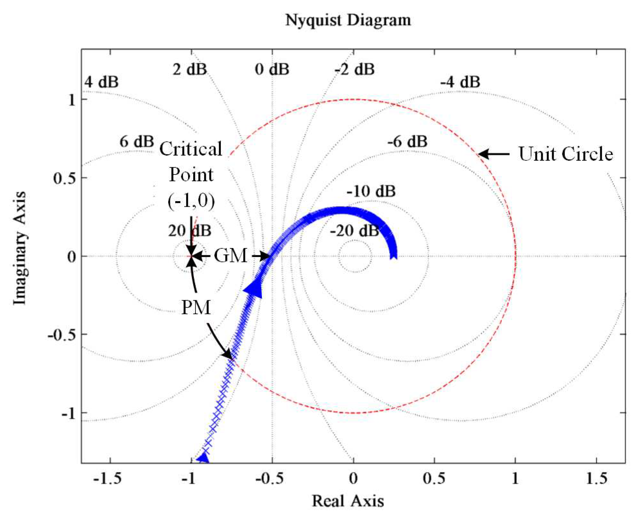
Using the proper gain according to the design procedure (i.e.,
and
), the Nyquist diagram of current control can be obtained in
Figure 8. The gain margin is 5.87 dB and the phase margin is 41.5
.
3.4.2. Control in Stand-Alone Mode
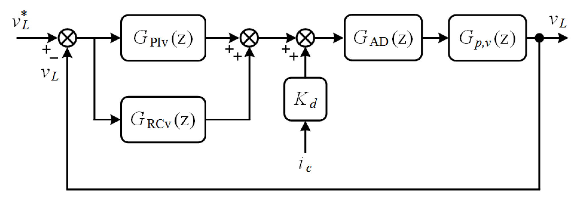
The PCS controls the load voltage by operating in SA mode, when a grid fault occurs.
Figure 9 presents a simplified block diagram of the voltage control. The load is provided low THD voltage less than 5% [
30]. Therefore, load voltage harmonic compensation method is needed. When non-linear load is connected, the
harmonic components are present at the load voltage. In order for the harmonic compensation, the repetitive control is adopted. The
(
z) is the PI controller transfer function for voltage control and the
(
z) is the RC transfer function represented by
where
is the gain of repetitive control,
N is the number of sampling frequency divided by the fundamental frequency (i.e.,
),
L is the sample periods in the next fundamental period, and
F(
z) is the low pass filter (LPF). The
F(
z) can expand the stability region considerably to improve the controller stability [
25]. In most cases, a zero-phase shift LPF is considered [
24]. The first order zero-phase shift LPF is given by
The coefficient,
, is determined by the following condition.
However,
F(
z) cannot countervail high frequency periodic disturbances completely. Therefore, some trade-off is needed between the tracking errors and system stability [
15].
is the time advance unit that compensates for the delays. The design of this component is based on the number of delay samples, which better approximates the delay of the transfer function at the harmonic frequencies. To obtain a reasonable
, the steady-state error and system stability are considered because a high
brings a small steady-state error, whereas the stability margin becomes small. According to the
filter resonance component in SA, the active damping is needed to make the system stable. The capacitor current and notch filter active dampings are used together.
is the capacitor current feedback coefficient6 and the
(
z) is the transfer function of notch filter discretized by the Tustin transformation [
34].
where the
,
is the sampling time, and
and
are the parameters of the notch filter expressed as
where
Q is the quality factor of the notch filter that determines the −3 dB rejection bandwidth and
is the notch filter frequency. Therefore, the
is placed at the resonance frequency to inhibit the resonance effect. When the rejection band,
, is specified, the quality factor,
Q, can be calculated by
and
(
z) is the transfer function of voltage control plant discretized by ZOH which is given by
The closed loop of the voltage transfer function can be obtained by
To simplify the stability analysis, the open-loop gain for the PI controller is given by
and the open-loop gain for repetitive controller is obtained by
(
14) can be rewritten as
where the
can be expressed as
The pole of the closed loop,
, which is defined as
should be within the unit circle in the
z-domain. In other words, the zero point of
should be within the unit circle of the
z-domain. Applying (
7) to (
18), the
can be rewritten as
where
is expressed as
To obtain a stable system, the zero point of
also should be within the unit circle in the
z-domain.
can be rewritten as
where
is given by
To guarantee
stability,
should meet the following condition, as expressed by
If (
22) satisfies the (
23) condition over all the frequency domain below the Nyquist frequency, the system becomes stable according to the small gain theorem [
15,
24,
25].
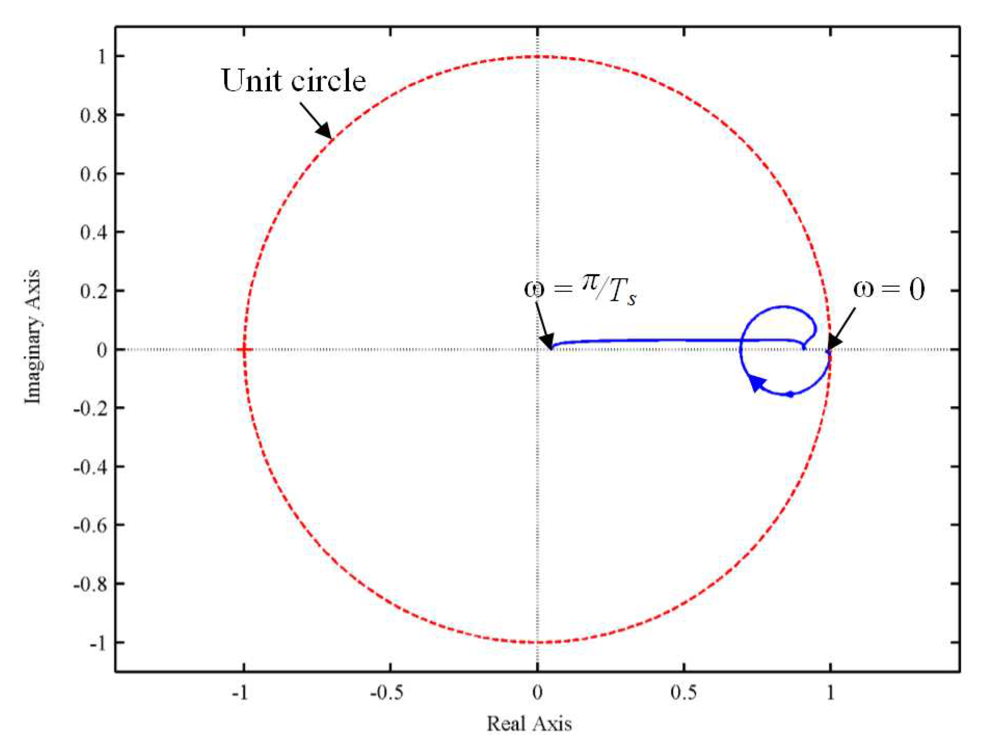
Figure 10 shows a Nyquist diagram of the voltage control with the proper gain; the proposed voltage control algorithm satisfies the stable condition (
23).
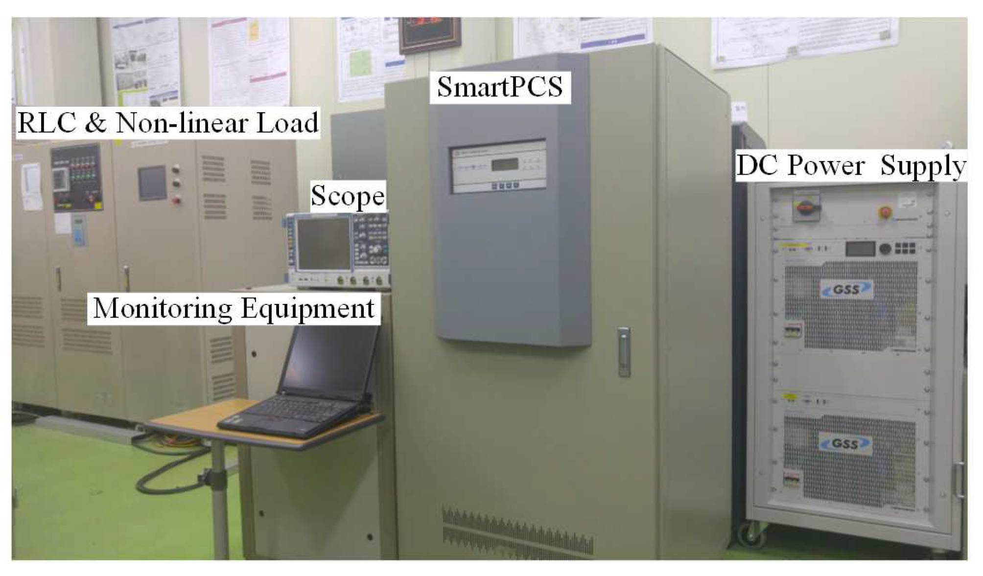
4. Experimental Results
The battery was simulated using a bi-directional DC power supply and a
load and non-linear load was used. The proposed control algorithm was fully implemented using the TMS320F28335 digital signal processor manufactured by Texas Instruments as shown in
Figure 11.
Figure 12 shows the experimental environment for verifying the proposed PCS algorithm. The experiment parameters of the proposed smart PCS are described in
Table 1. Considering the load conditions that can occur in the actual system, the experiment is conducted for the following six cases.
- (1)
Low PCS output power with a light load.
- (2)
Low PCS output power with the rated load.
- (3)
Rated PCS output power with a light load.
- (4)
Rated PCS output power with the rated load.
- (5)
Non-linear Load.
- (6)
NDZ condition Load.
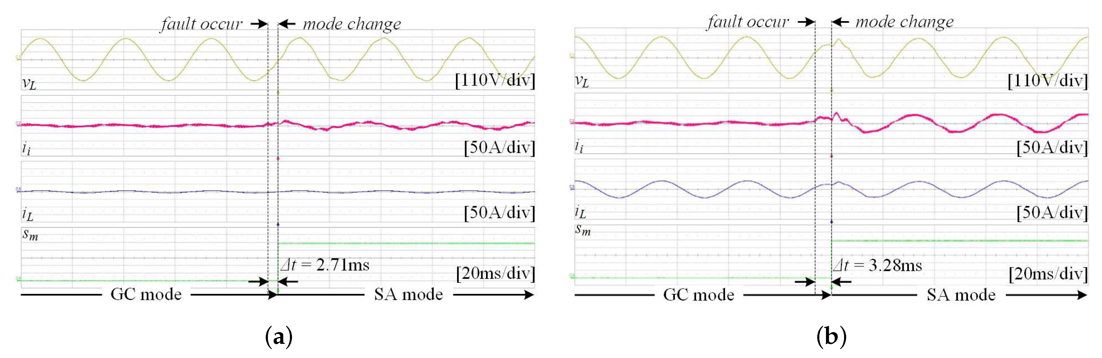
Under normal grid conditions, the PCS operates in GC mode to control the grid current using the active frequency drift with a positive feedback method. When an abnormal grid state occurs, the PCS detects the fault signal and changes its operation mode from GC to SA mode. The time taken for the PCS to recognize the abnormal condition and switch the operation mode is called the transient time,
. The experimental results in
Figure 13 shows the low output power of the PCS condition (i.e., 100 W output power).
Figure 13a shows that a light load, 1 kW, is connected to the PCS of low output power. Because the difference between the output power of the PCS and the power consumption of the load is small, it can be confirmed that there is little fluctuation of the load voltage upon changing the mode, and the transient time is 2.71 ms. The rated load, 30 kW, is connected to the PCS of low output power as shown in
Figure 13b. In this case, because there is a difference between the PCS and load, a slight transient occurs during the transient time. However, this is within the specified range, and
is 3.28 ms.
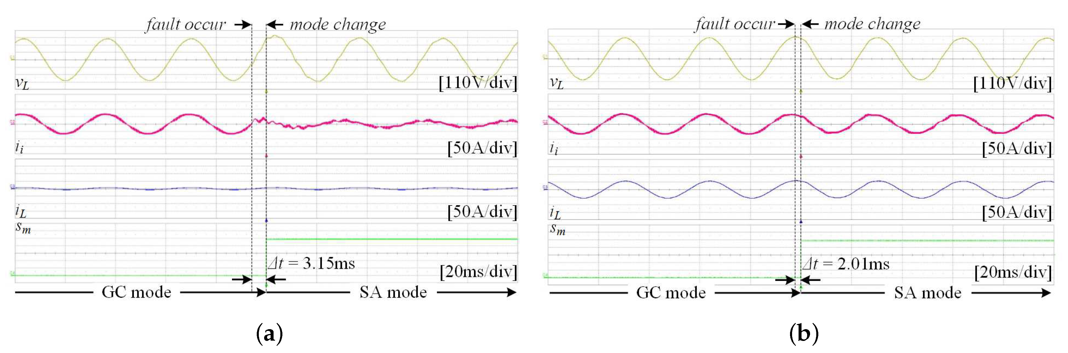
Figure 14 shows the resulting waveform of 30 kW PCS power. The load voltage changes slightly after the grid abnormal state and the PCS changes its operation mode within 3.15 ms and 2.01 ms as shown in
Figure 14a,b, respectively.
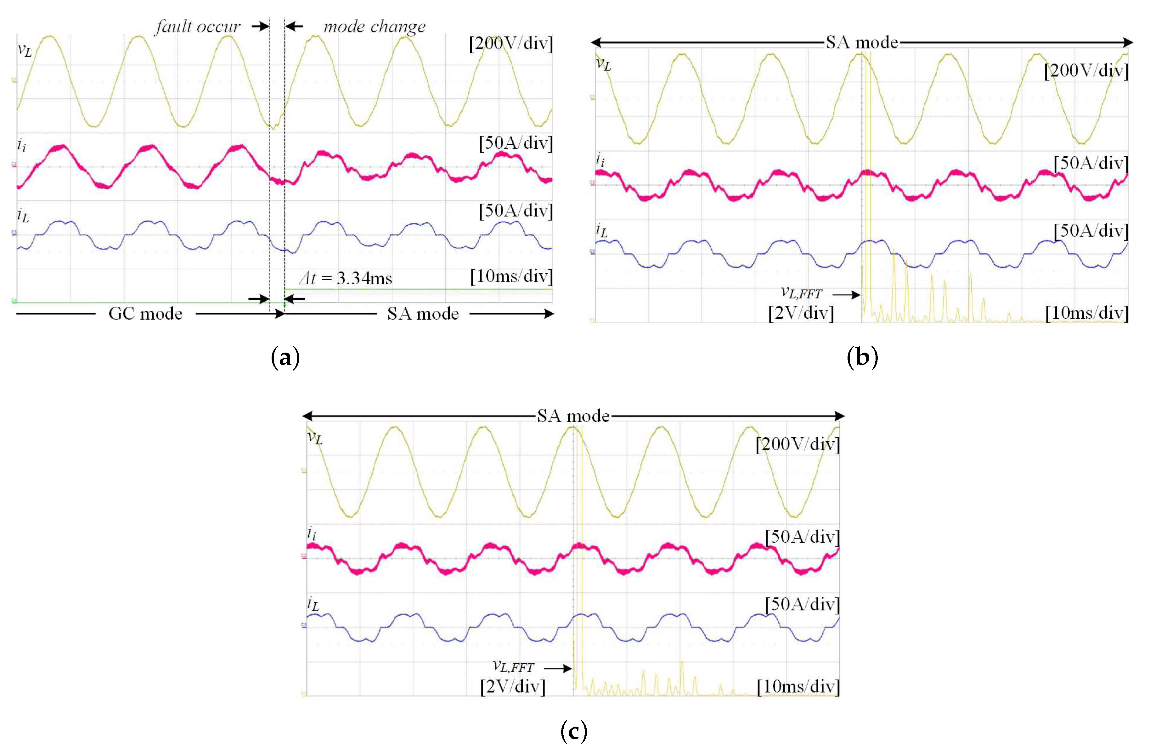
Figure 15 shows what occurs when a non-linear load is connected to the PCS. Before the compensation for the nonlinear load is performed, it can be confirmed that the distortion occurs in the load voltage waveform. The waveform of the fast fourier transformation (FFT) result of this load voltage shows that the voltage quality is deteriorated by the harmonic components of
,
n is an integer, (e.g., 5th, 7th, 11th, 13th, ...).
Figure 15a presents a transient state when non-linear load is connected. Even if a non-linear load is connected, the operation mode is changed within 3.34 ms and a stable voltage is supplied to the load.
Figure 15b,c show the experimental waveform before and after the harmonic compensation of the load voltage is applied.
Figure 15b shows the voltage and FFT waveforms of the load before applying the harmonic compensation algorithm in SA mode. Approximately 5.8% of the load voltage THD was measured, which means that the voltage THD does not meet the harmonic regulation to maintain within 5% [
30]. After the harmonic compensation algorithm was applied as shown in
Figure 15c, the lower harmonic components of the load voltage in the FFT waveforms decreased remarkably and the THD also decreased to approximately 2.3%. This can satisfy the harmonic regulation.
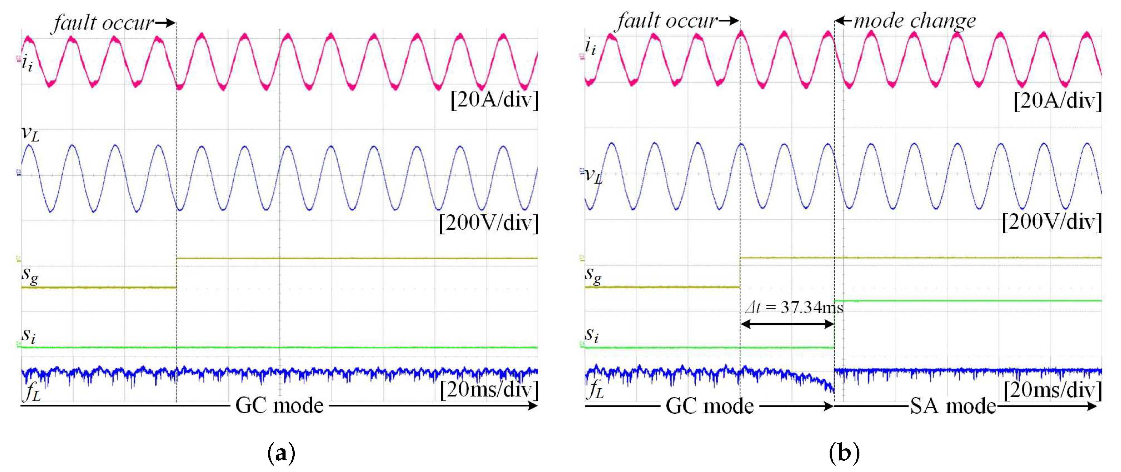
Figure 16 shows the experimental results of the NDZ condition. The NDZ occurs when the load fluctuation is small so that the PCS cannot be detected as an accident even if an abnormal grid condition occurs. In this case, the load is supplied continuously with power. On the other hand, from the perspective of the entire system, secondary damage can occur if the PCS cannot deliver accurate information to the transmission system operator.
Figure 16a shows an experimental waveform without a NDZ escape algorithm. The load voltage and the frequency are kept constant, even when a grid fault occurs (i.e.,
changes from low level to high level). However, the PCS cannot recognize it and open the inverter side switch,
.
Figure 16b shows the experimental result using the escape NDZ method. When a grid fault occurs, the load voltage remains constant, however, the load frequency changes gradually to reach the fault level. After that, the PCS recognizes the fault situation and changes its operation mode. The transient time is long, however, this is not a serious issue because detecting the accurate grid condition is the main purpose and the load is also provided the power from the PCS constantly.
5. Conclusions
In this paper, a novel seamless transfer algorithm that enables power conditioning system (PCS) to implement UPS function. It was confirmed that the proposed algorithm operates without any abnormality through various experimental conditions. During the grid-connected mode operation, the PCS performs the current control and detects the presence of the load in the NDZ condition where the existing PCS cannot detect accurate grid information, so that the operation mode can be switched. The transient phenomenon is minimized by applying the seamless transfer algorithm when the operating mode of the PCS is changed due to the grid abnormality. During stand-alone mode operation, the load is supplied with voltage from the PCS. For non-linear loads, the THD of the load voltage is 5.8%, which does not satisfy the IEEE standard. Therefore, the THD of the load voltage is reduced to 2.3% through harmonic compensation, so that high quality voltage can be supplied. It was confirmed that the transfer of operation mode occurred within 4 ms in all experiments. Operation in unbalanced loads, and operation in a parallel system should be continued in future studies. The algorithm proposed in this paper was applied to the PCS for the emergency power supply of the control equipment of Korea Gas Corporation.


