1. Introduction
The substantial increase in the use of electrified collective transport systems, which has occurred in recent years in large urban centers, has made it necessary to increase the vehicle frequency rate and capacity of convoys in terms of transportable passengers. This has been reflected in the use of vehicles with more propulsion power, as well as lower time displacement, with consequent voltage variations, which are critical factors in the proper operation of the transport system. Maintaining the line voltage within certain limits is in fact dictated by the need to properly power the input bus of the electrical traction drive, which is currently the most popular propulsion system in metropolitan, tram, and tramway trains. Major voltage drops in the line occur mainly at the acceleration stages of the convoys and are therefore directly related to the number of vehicles simultaneously operating on the line and to the total power required. During the braking phases, however, the kinetic energy of a convoy is converted into electrical energy and, if possible, supplied to the other accelerating convoys.
In this context, the use of braking energy recovery storage systems located along the contact line or near the passenger stations could result in significant energy savings, compensating for the costs incurred for their installation. The stored energy could also help to support the contact line during consecutive congestion restarts, thus reducing voltage drops and energy dissipation. Among the different rail transport systems, a solution with energy storage systems can be particularly effective and beneficial if applied to metropolitan, suburban, and tramway systems. In fact, these are characterized by operating convoy sets that accelerate and brake in short time intervals. In such applications, the placement of the energy storage system in the station is optimal because of the availability of space and therefore may be preferable to on-board installation. This solution also enables recovery and re-use for other convoys passing near the same station.
Energy storage systems are essentially made up of components for energy storage and static energy converters that regulate the incoming and outgoing energy flows, ensuring high reliability and high efficiency. These controlled converters have to be installed between the feeding lines and storage components in order to manage bi-directional flow of electrical energy.
Supercapacitors (SC) are a good alternative to electrochemical batteries in applications where it is necessary to quickly compensate for the discontinuous power absorption of electric loads. A proper storage capacity design allows the use of SCs in different practical applications.
In the recent past, the scientific community has been paying growing attention to the different uses of these technologies in urban and suburban railway traction systems (streetcar, light rail transit, and mass rapid transit) [
1,
2]. In fact, it has been widely demonstrated that their use enables both the under sizing of the power supply plant in the project stage or a more intensive use of existing subsystems without major modifications (e.g., the repowering of electrical substations and the increase of the cross-sectional area of contact wires), and besides it definitely allows to improve the overall energy efficiency thanks to the recovery of the braking energy and its subsequent release in the starting phase of the traction motors. Moreover, their intervention involves the benefit of avoiding overvoltages on the overhead contact line which become more receptive.
Practical employments of storage units can be either stationary or mobile [
3,
4,
5]. In the first case, they can be used to reduce the energy demand of the whole system and to stabilize the supply network voltage at weak points (e.g., the voltage drops typically associated with end of lines) with the potential elimination of additional feeding substations [
6]. In addition, this solution can greatly contribute to the peak shaving action of traction power during the acceleration of vehicles, as the storage unit is capable of recovering energy from several braking vehicles at the same time with any limitation in terms of weight and required space for installation.
In mobile applications, the storage units are installed on-board and, hence, are used for the shaving of power peaks demanded during the acceleration of vehicles, which leads to reduced energy costs, limitation of voltage drops, and minimum resistive losses in the supply line and improves efficiency by recovering mechanical energy during braking [
7,
8]. The management of the regenerated energy is simpler, since the control is independent of traffic conditions and the action could be also useful to have a certain power autonomy, e.g., in emergency catenary free operation.
In the literature, remarkable attention has been devoted to the efficiency of the energy storage unit operating mainly as a support system for the contact lines voltage in urban and suburban railway traction networks, because this practical application can be useful for problems that arise today, especially in many large cities, when new generation vehicles are put in operation on feeding lines not modified or correctly executed according to the increase of the absorbed current. This, together with the stringent need to increase the passenger carrying capacities as well as the vehicle’s frequencies during the day, can cause overloading of the contact lines, with consequent operating voltage drops and probable intervention of minimum voltage protection relays.
To avoid this situation, a quick and effective solution to improve supply line performance and prevent unwanted voltage drops without further modification in the existing feeding infrastructure is the use of SC stations allotted along contact line sections [
9]. Naturally, the achievement of these targets is closely linked to the proper design of SC sets in terms of size and capacitance, the number and locations of the stations, and the control strategies of the power electronic devices [
10,
11].
In order to achieve a satisfactory braking energy recovery, it is necessary to consider that the amount of energy that can actually be recovered during vehicle braking and reuse is only a part of the kinetic energy owned by the vehicle itself at the start of braking. This part is smaller than the power losses incurred in converting the kinetic energy into electric energy and transferring it to the storage components. In practice, the efficiency of the electrical traction motor during generator operation is very high. The leaks in static converters are very low, because of their high efficiency. Joule leakage losses in the conductors between the storage systems and contact lines increase considerably with the distance between the storage device and the point where the vehicle brakes, because braking is a short-term phenomenon and is generally constrained to deceleration values that are easily acceptable to passengers. Consequently, the power and current values involved are relevant. These losses can, therefore, also counteract the energy recovery benefits. Therefore, the use of energy recovery storage systems for tramcars can only be effective with the on-board installation of the systems themselves. Their arrangement along the contact lines may be useful when they are used to support contact line voltages. In our opinion, this last goal can be achieved, together with an optimal recovery of braking energy, by integrating the recharge of stationary SC energy storage sets with energy from local photovoltaic (PV) sources appropriately installed along the rail path.
There have been a few recent papers that have dealt with the application of PV sources to urban railway networks. In [
12], the authors investigated the performance of solar PV modules mounted on the roof of a rail coach to quantify the reduction in diesel consumption of the end-on generation system that powered the electrical load in the new generation coaches.
A roof coach installation of the panels was proposed in [
13], which introduced a technical scheme for the auxiliary power supply system of a passenger train based on PV and battery energy storage. This auxiliary power has to be injected into the direct current (DC) power supply system in order to obtain an annual output power payback, energy conservation, and emissions reduction [
14,
15]. Moreover, Becherif et al. [
16] presented the concept of an embarked power source using SCs that were charged by means of a combination of a roof-placed PV source and an aero generator, which supplied power to the DC link of the main traction drive. The design and energy management strategies were applied to a miniature train in the laboratory.
In [
17,
18], the potentials, peculiarities, and prospects of using solar power generation systems on the platform roofs of railway stations were analyzed for power injection into the main electrical grid. The prospects for realizing a solar generation system with lithium ion batteries for a local station, called a “zero-emission station”, were also shown to realize a more eco-friendly traction power supply system [
18].
Ultimately, in [
19,
20,
21], the feasibility and application modes of a fixed PV generation system with an auxiliary SC or battery storage equipment were studied for urban rail transit. The alternating current (AC) grid-connected mode and DC grid-connected mode were presented, and the grid-connected topology and energy management strategy were developed. The intrinsic capability of saving regenerative energy with a consequent increase in the energy savings of the systems and reduction in the voltage drop was highlighted.
This paper proposes a procedure for the optimal integration of PV power plants, SC storage systems, and railway power systems. The PV modules are installed on the available surfaces of shelters positioned along the track. In order to use a modular approach for the storage systems, each shelter is also provided with SC units. The modular distribution of storage systems makes it possible to improve the discharge phase, reduce the losses in the connection to the railway power system, and improve the control because it is possible to act in a different manner in the various nodes of the railway systems. The approach utilized for the optimal integration is based on the use of a random optimization procedure. This is based on a minimization cost function that takes into account the cost of the entire system and can solve the mathematical problems with integer variables. Some simulations were performed taking into account the case of a tramway of Naples (Italy) and using the software Matlab© and Simulink© (R2017a, Mathworks, Natick, MA, USA).
2. The Photovoltaic Power Plant
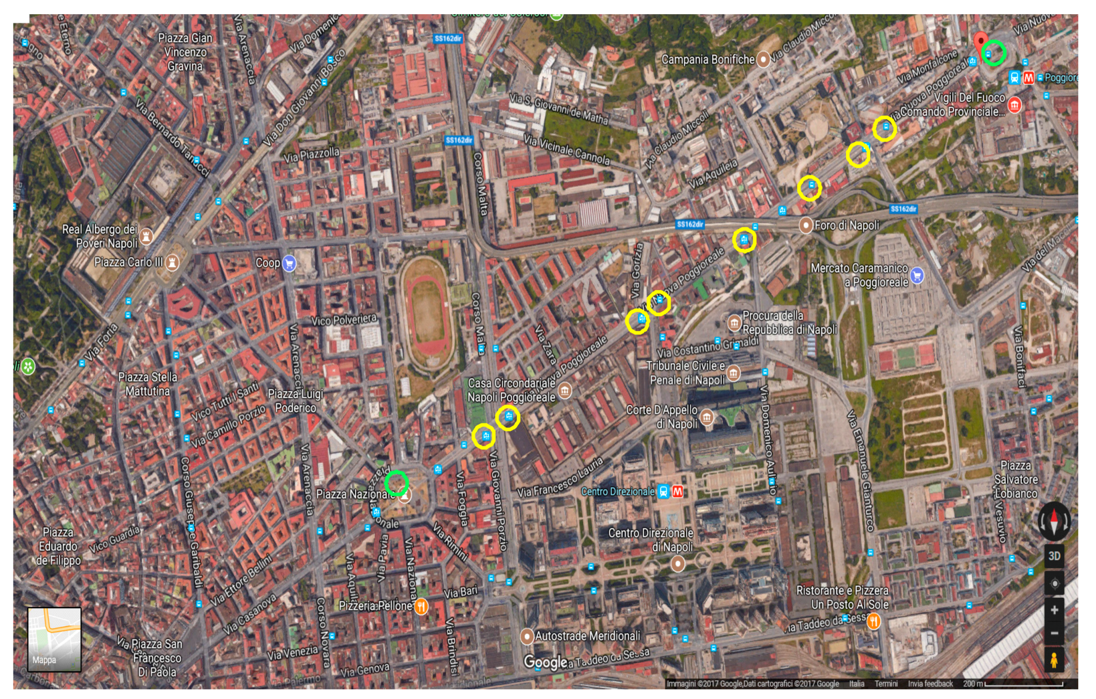
The considered tramway track, which is shown in
Figure 1, is approximately 1.8 km long and has five stops placed 300 m apart. The total time needed to pass over this track is about 300 s. A yellow circle in
Figure 1 indicates the presence of one shelter, while the green circles correspond to two shelters. The green circles are also positioned at the initial and final stops of the track. At each shelter, it is possible to install five PV panels with the characteristics reported in
Table 1.
The maximum power generated by a plant assembled on a single shelter is about 1 kWp. Considering the total number of shelters, it is possible to install 12 kWp of PV panels along the entire track. The electrical power generated by this power plant can be utilized by connecting the PV panels directly to the low-voltage power system through an inverter to exchange electrical energy with the power system, or by linking the panels to a storage system based on SCs and using the energy during the tramway operation.
In recent years, because of the large development of distributed generation, the management of power systems, particularly low-voltage systems, has been affected by new problems related to the voltage drop along the line and the sorting of the locally generated energy. Therefore, the necessity of integrating storage systems in the power system continues to grow. Another important problem introduced by the integration of distributed generation in the power system is the random behavior of renewable energy sources. The feasibility of PV power plants is based on a study of the annual solar radiation that is typical for a geographical location.
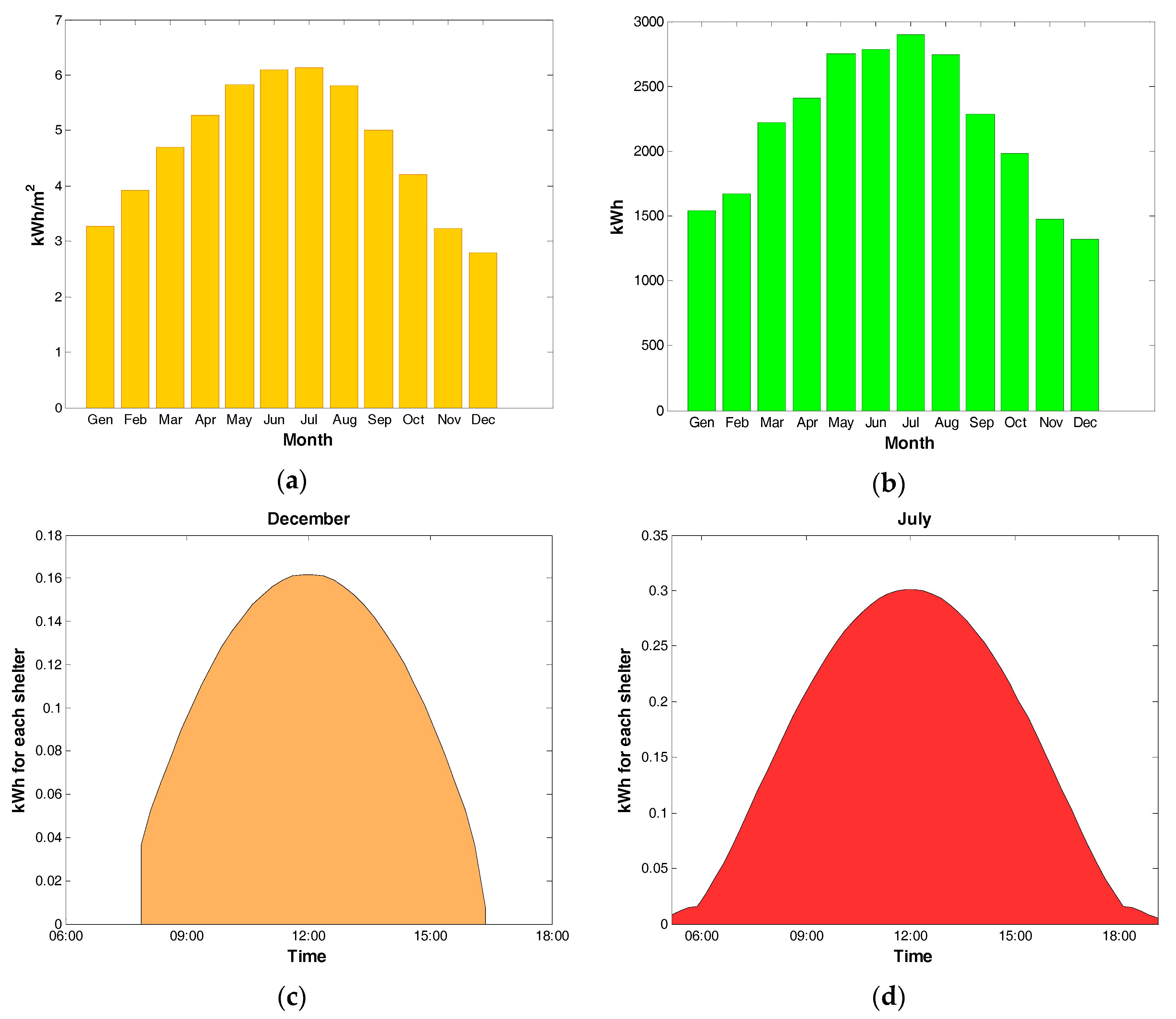
Figure 2a shows the mean value of daily global radiation in the case considered in this paper [
22] in kWh/m
2.
Considering the efficiency of the PV panels (
Table 1), a power electronic converter global efficiency of 0.96, and the total surface of the shelters, it is possible to compute the mean value of energy (
Figure 2b) generated by the considered PV power plant.
The mean value of achievable energy in a year is approximately 26,000 kWh. Considering the high power required in traction applications, the PV power plant cannot be directly coupled to the railway lines, so it is necessary to use an appropriate storage system, i.e., one based on SCs, and to integrate it in the tramway electric power system. The integration of a PV power plant in the railway system requires an appropriate analysis of the distribution of solar radiation during a day to avoid oversizing the storage system. Solar radiation is quite variable during the day. Thus, forecasting is difficult, and it is usually evaluated using statistical data. A correct knowledge of the radiation permits the optimal sizing of the storage systems.
Figure 2c,d reports the average values of solar radiation [
23] in the summer and winter months for the case considered in this paper.
Figure 2c,d shows the obvious and substantial difference between winter and summer, which must be taken into account for the correct sizing of the energy storage systems.
The choice of a storage system with a capacity equal to the maximum recovery energy in summer is oversized with respect to the energy available in winter. Thus, it is necessary to consider the possibility of storing only a part of the energy obtainable by the PV power plant and exchanging the other part with the distribution power system. The energy storage depends on the behavior of the electrical load in the considered railway systems. The total duration of a single track is about 300 s, with five stops, and the total energy that can be stored in 300 s is very low. Thus, it is necessary to consider a longer interval (more tramway rides) to obtain a reasonable amount of energy and increase the life of the storage system by reducing the number of charge and discharge cycles.
3. The Photovoltaic Power Plant
The integration of the SCs in the railway power system is modular. The modularity of the storage systems involves the installation of multiple SCs near the shelters along the track, which increases the system reliability, prevents the complete exclusion of the storage systems during maintenance, introduces some optimal strategies for reducing losses, and minimizes the installation cost.
The electric scheme of the railway power system with the PV modules and SCs is shown in
Figure 3. The railway power system is fed by a transformer with a primary voltage of 20 kV. The secondary side includes a bridge rectifier that outputs a voltage of 750 V. During its performance, the voltage in the different nodes of the net can vary in the range of 600–900 V. The output of the bridge rectifier is linked to the catenary of the power system.
Table 2 reports some data of the railway power system [
24].
In the literature, some AC schemes are used for the integration of renewable energy sources in power systems [
25,
26]. In particular, this scheme can be optimized through the use of a reversible optimal power flow, which also avoids the use of storage systems and permits the regulation of energy price in the market and some ancillary services. Considering the scheme of
Figure 3, it is not possible to recover energy through the Medium Voltage (MV) substation, because this implies a high economic investment for the replacement of the rectifier diode (usually coupled with three windings transformers) with a bidirectional rectifier; for this motivation, the recovery and the use of energy from the tram braking or from the PV installed on the shelters can be done by means of an energy storage system. Due to the high value of current necessary during the acceleration (or charge current available during the deceleration), a supercapacitor is the most suitable technology for the application.
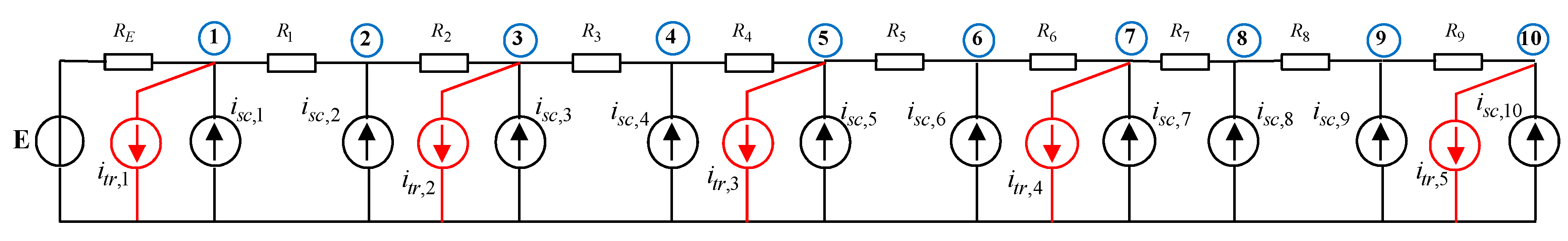
The PV modules are connected to the storage systems through a buck converter. In the same way, the storage systems are linked to the railway power system with a buck converter. A storage system can be installed at the end of the track to recover the energy generated by the train during braking. The electric layout of the system can be modeled as shown in
Figure 4.
The output of the transformer is considered constant, and both the train and storage system units are considered to be current generators.
RE is the resistance between the substation and the first node of the net, and
Rj (
j = 1, …, 9) are the line resistances between the different nodes. The stops are positioned along the track at nodes 1, 3, 5, 7, and 10. The mathematical model can be used for the following systems:
Function
Sh(
t) is a function that has values of 0 when the train does not start from node
h and 1 when the train starts from the considered node. The model obtained with relations (1) and (2) is valid considering a quasi-stationary performance of the system [
27]. In fact, the regulation transient of the chopper is considered to be very fast, and choosing an adequate stepping time for the simulation makes it possible to neglect the dynamic of the chopper and consider the output voltage to be constant.
4. Random Searching Optimization Problem
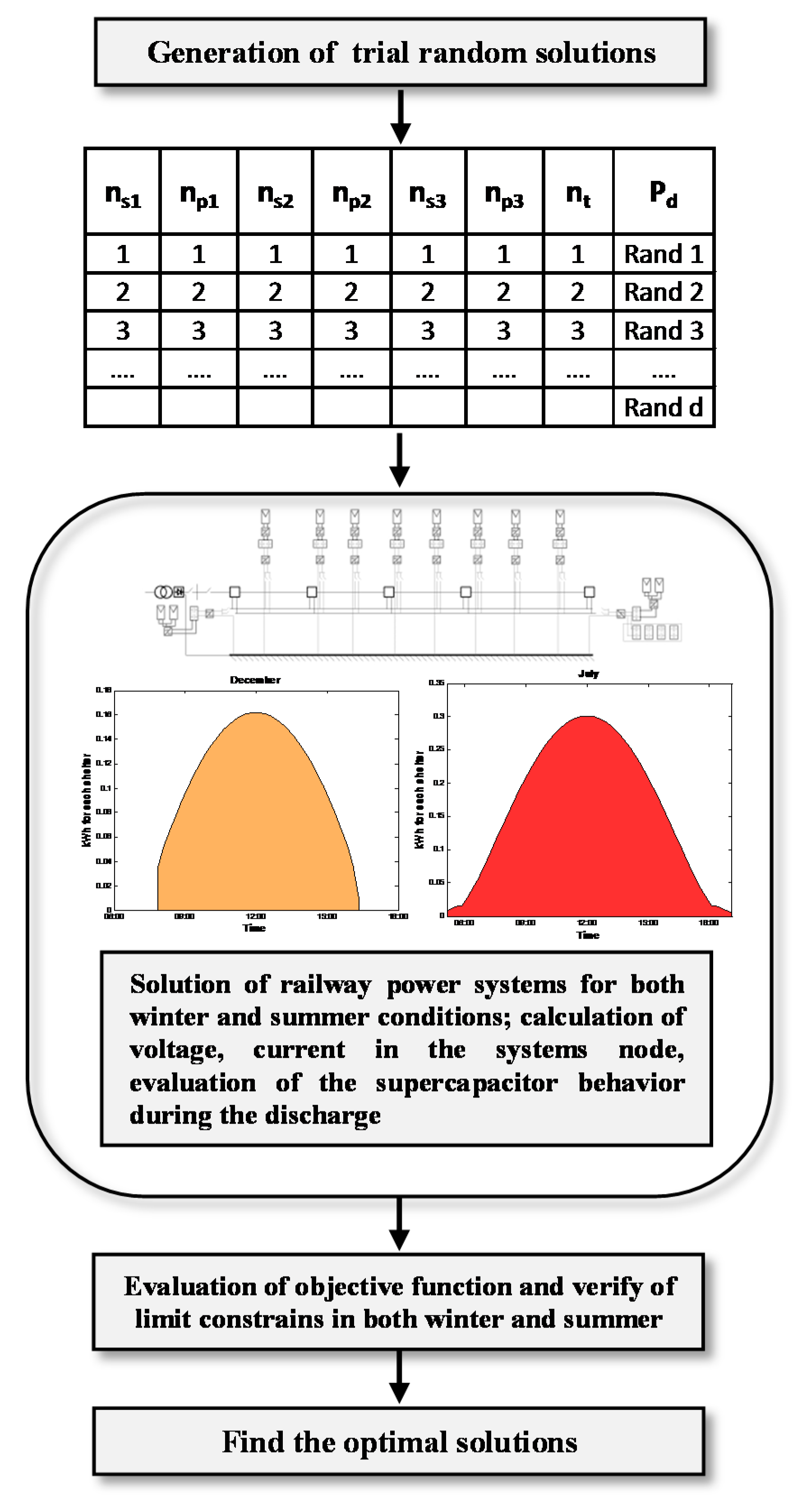
The optimal integration of PV plant and SC energy storage systems in the railway power systems is carried out by means of an optimization procedure based on a random searching algorithm. This procedure is suitable for performing the minimization of an objective function, usually depending on integer variables, starting from a set of possible solutions of unknown variables and using an iteration procedure that calculates the new value of cost functions using a random uniform distribution of unknown variables. After a certain number of iterations, the minimum (or maximum) obtained value of the objective function determines the optimal solutions. In the case considered in this paper, the optimization variables are the number of series (nsh) and parallel (nph) SCs used on each shelter (it is supposed that the numbers of SCs are equal in the intermediate shelters and different at the first and last stops) and the number of complete track sections performed by the train (nt) during which the energy obtained by the PV cells is stored in the SCs. The last random variable utilized is the discharge power Pd of the SCs in the discharge process (divided into Pd1 and Pd3 for the final and initial shelters, respectively, and Pd2 for the intermediate shelters).
All of the variables are strictly related to the electrical optimization of the net, because they determine the improvement of the total power dissipated in the railway system. The optimization problem is resumed in the following system:
In (3),
c1,
c2, and
c3 are weight parameters in Euro/kWh related to the cost of the SCs (Δ
E is the energy stored in a single SC unit), the cost of the energy losses (
Eloss), and the cost of the energy generated by the PV cells (
Epv,p) and exchanged to the power system. The optimization procedure takes into account the solution of a complete track section for the train with all the stops, along with the calculation and evaluation of the cost functions for each combination obtained by the procedure (
Figure 5).
The time dependence of variables Vh and Isc,h is directly considered because the optimization procedure simulates the complete railway track. The minimum and maximum voltage limits for the considered electric system are 600 V and 900 V, respectively, while the maximum discharge current depends on the type of SC adopted.
5. Optimization Results
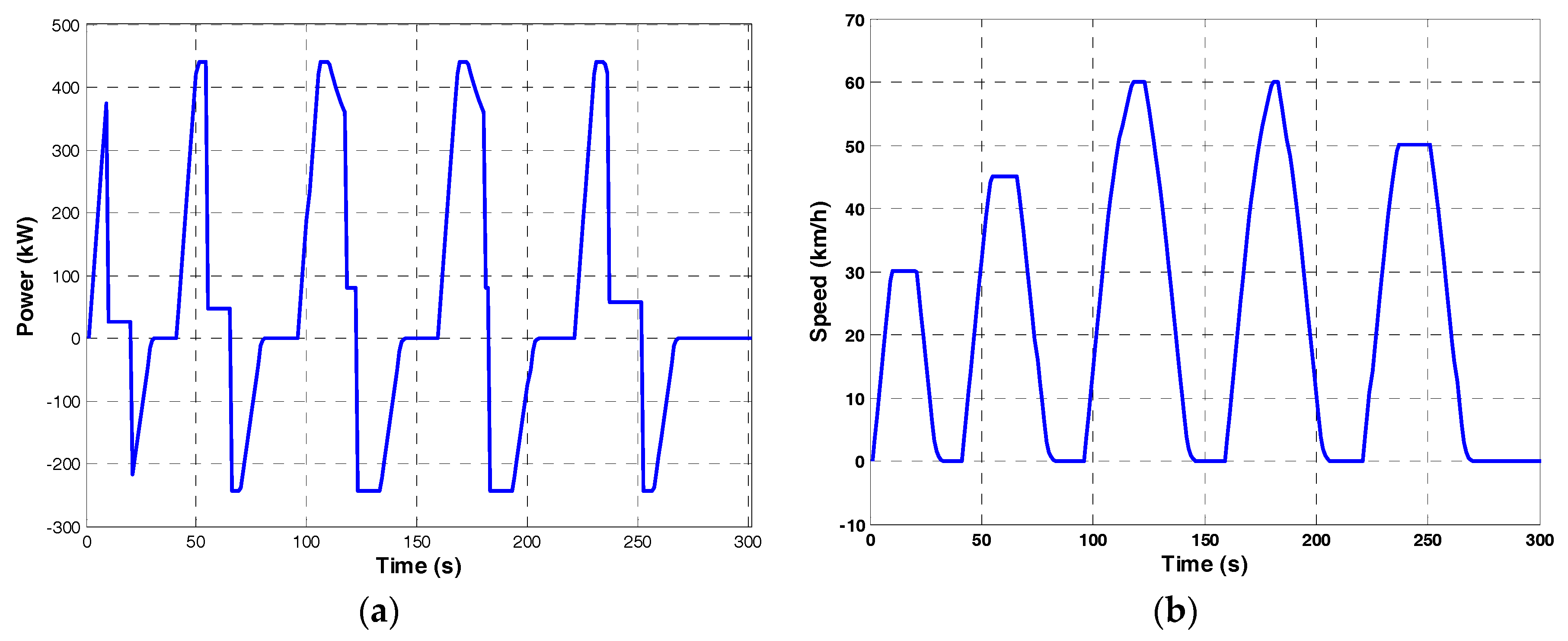
The optimization procedure is applied to the considered railway track, and the mechanical power and speed profile of a train traveling on the railway are respectively represented in
Figure 6a,b. As can be noted, the profiles are typical of light railway power and speed profiles, with numerous accelerations and stops; this also shows that the current absorption presents numerous peaks, which can influence the behavior of the power electronic converter installed in the power system. The power stored in the SCs is supplied during the acceleration phases in order to reduce the total power absorbed by the substation. The optimization procedure was implemented considering SCs with the features reported in
Table 3.
The random optimization procedure was carried out with 17 iterations, fixing
c1 = 30,000,
c2 = 0.2, and
c3 = 0.1.
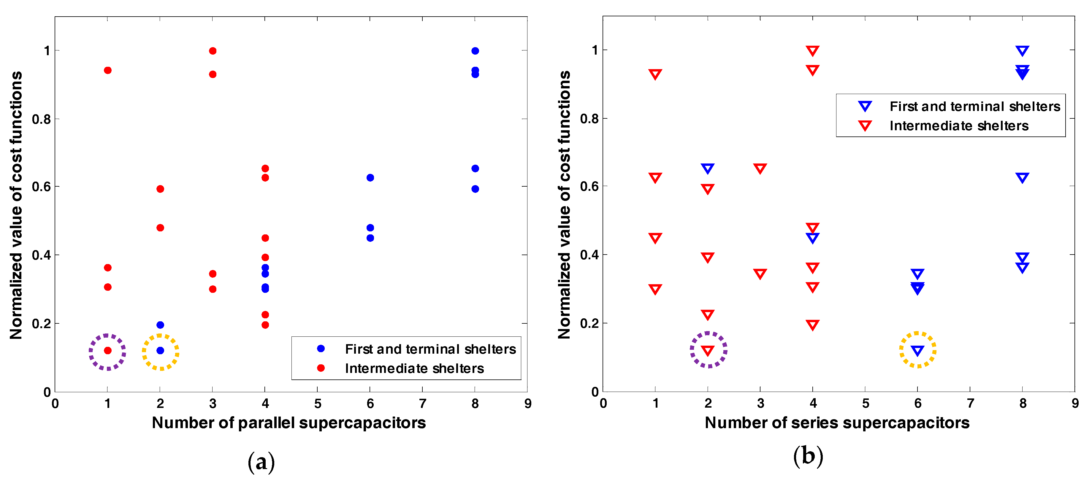
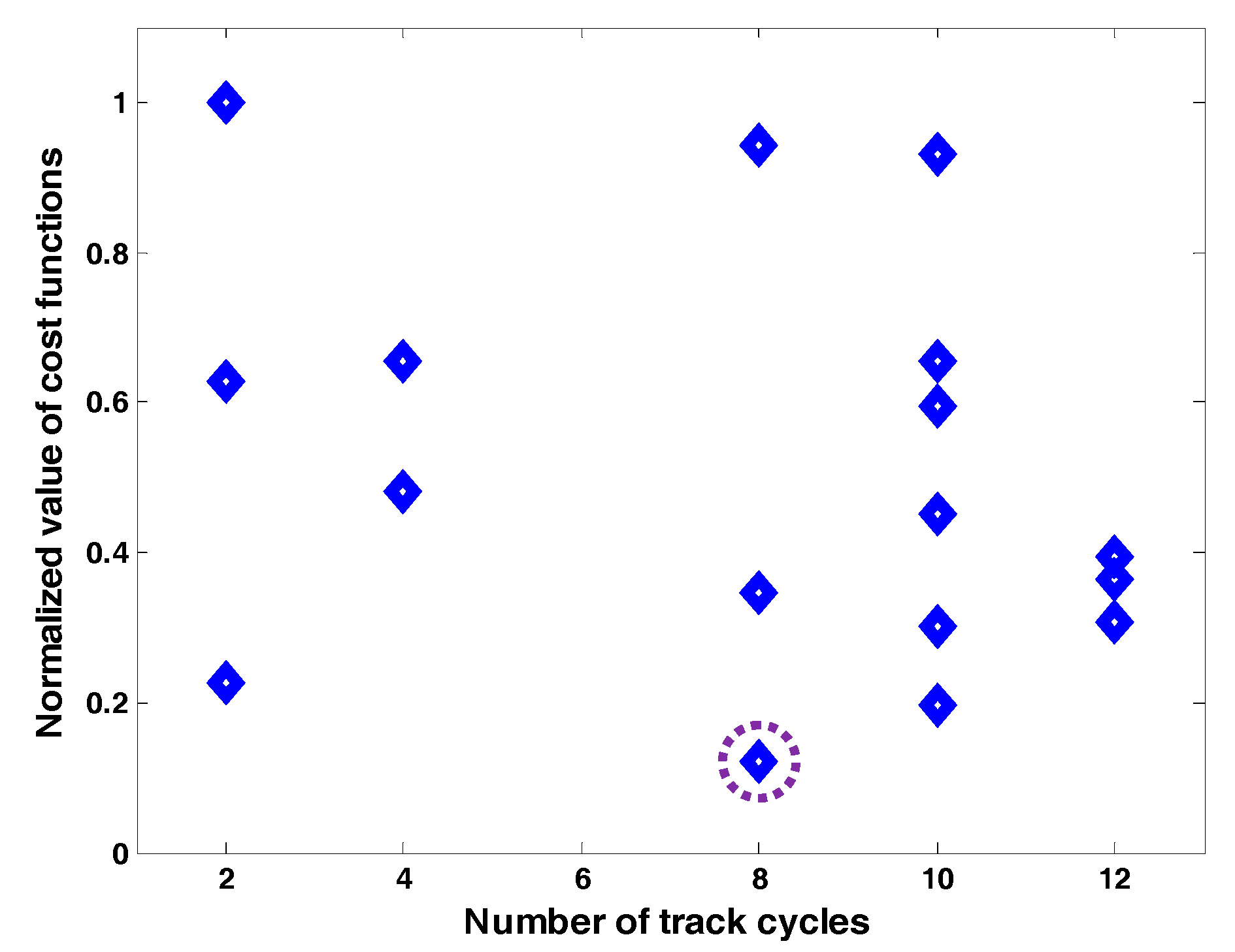
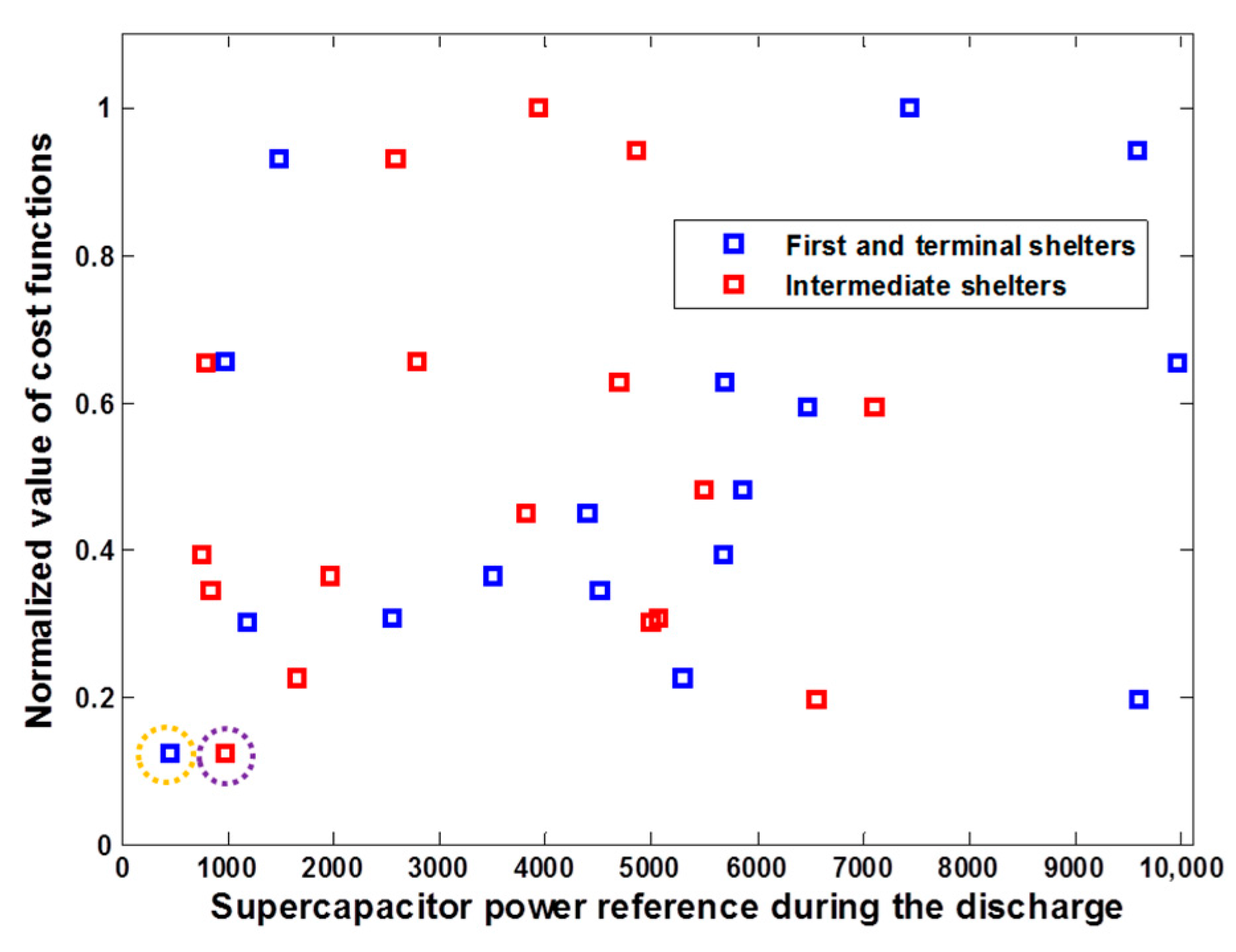
Figure 7a,b shows the parallel and series SCs that must be installed at the initial and terminal stops (blue) and in the intermediate shelters, while
Figure 8 shows the normalized cost function with various interval recharge times for the SCs, and
Figure 9 shows the distribution of the cost function values as a function of the discharge power.
The results obtained through the optimization procedures are reported in
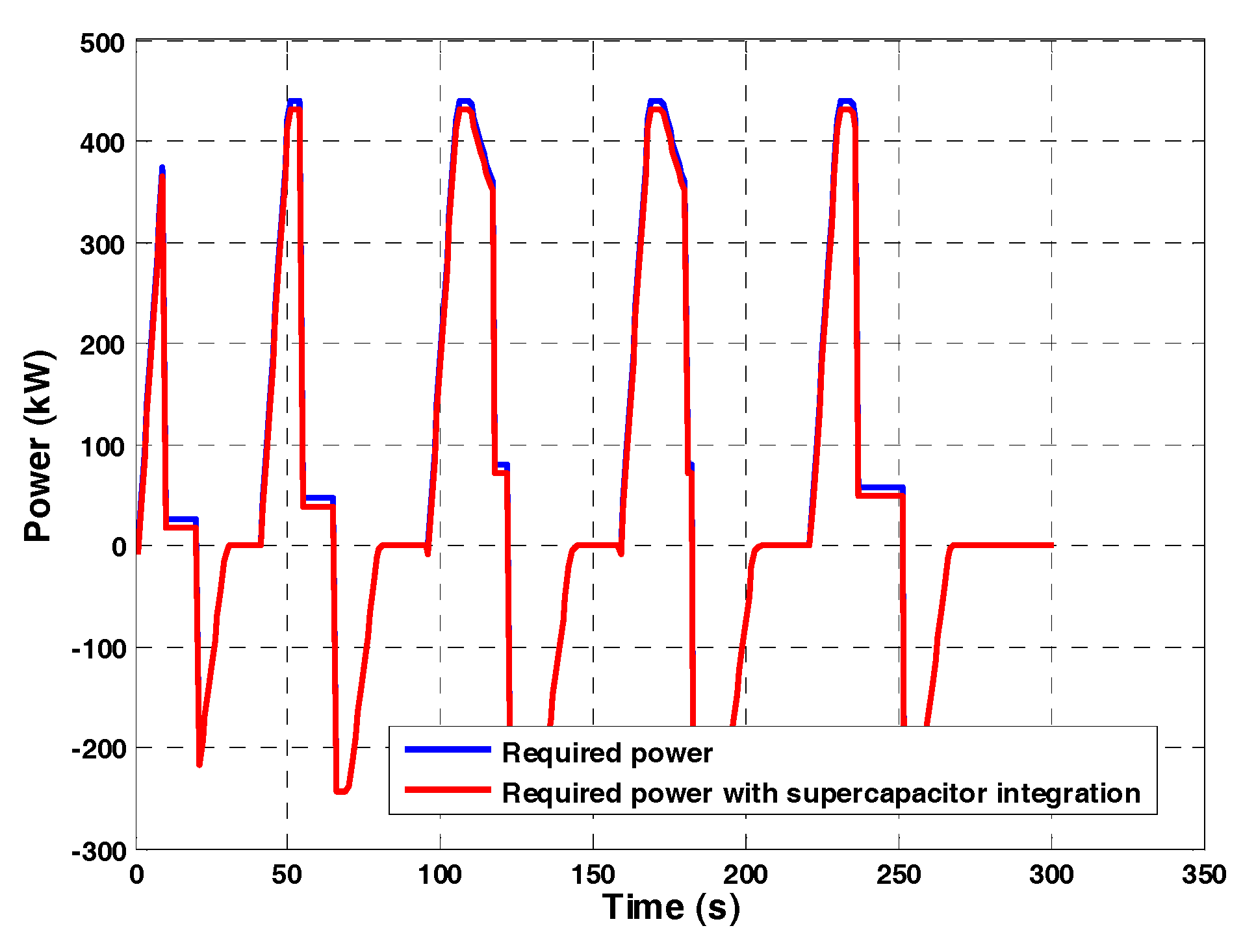
Table 4. The optimal value of the cost objective function is approximately 199 kEuro, which was practically determined by the high cost of the storage unit systems and could be reduced by the improvement and production of new SCs. The positive role of the SC is also inherent to the reduction of the peak power required for the distribution power systems.
Figure 10 shows the new trend for the power required by the train.
In the proposed procedure, the SCs are controlled to keep the power used during the discharge process and train acceleration phases constant, but it is also possible to completely discharge the SCs in a limited time, which corresponds to the maximum value of power required.
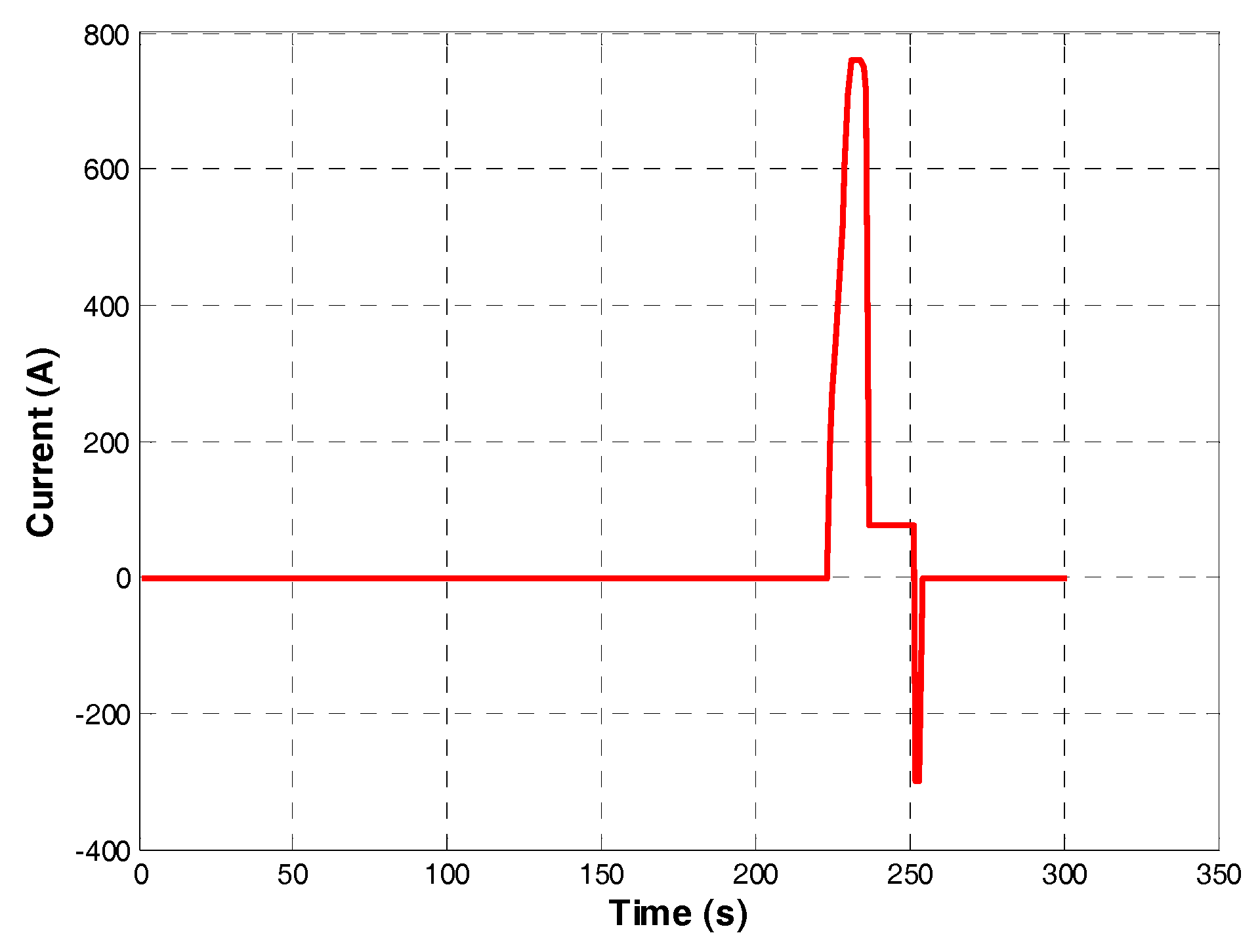
Figure 11 and
Figure 12 show the trend of voltage and current in node 10 during a typical winter day. The voltage profile highlights that the maximum and minimum values of voltage are respected; also, the current respects the imposed constraints; the maximum value of current is reached when the tram passes through the last stop. In the previous instant, the current of node 10 is about 1 A (this behavior permits also the reduction of Joule losses along the tramway power system).


