Article

Anti-Agglomerator of Tetra-n-Butyl Ammonium Bromide Hydrate and Its Effect on Hydrate-Based CO2 Capture

1
Guangzhou Institute of Energy Conversion, Chinese Academy of Sciences, Guangzhou 510640, China
2
Key Laboratory of Gas Hydrate, CAS and Guangzhou Center for Gas Hydrate Research, CAS, Guangzhou 510640, China
3
Nano Sciences and Technology Institute, University of Science and Technology of China, Suzhou 215123, China
4
Guangdong Key Laboratory of New and Renewable Energy Research and Development, Guangzhou 510640, China
*
Author to whom correspondence should be addressed.
Energies 2018, 11(2), 399; https://doi.org/10.3390/en11020399
Submission received: 14 December 2017 / Revised: 30 January 2018 / Accepted: 31 January 2018 / Published: 8 February 2018
(This article belongs to the Special Issue Carbon Capture and Storage)

Abstract

:
Tetra-n-butyl ammonium bromide (TBAB) was widely used in the research fields of cold storage and CO2 hydrate separation due to its high phase change latent heat and thermodynamic promotion for hydrate formation. Agglomeration always occurred in the process of TBAB hydrate generation, which led to the blockage in the pipeline and the separation apparatus. In this work, we screened out a kind of anti-agglomerant that can effectively solve the problem of TBAB hydrate agglomeration. The anti-agglomerant (AA) is composed of 90% cocamidopropyl dimethylamine and 10% glycerol, which can keep TBAB hydrate of 19.3–29.0 wt. % in a stable state of slurry over 72 h. The microscopic observation of the morphology of the TBAB hydrate particles showed that the addition of AA can greatly reduce the size of the TBAB hydrate particles. CO2 gas separation experiments found that the addition of AA led to great improvement on gas storage capacity, CO2 split fraction and separation factor, due to the increasing of contact area between gas phase and hydrate particles. The CO2 split fraction and separation factor with AA addition reached up to 70.3% and 42.8%, respectively.

Graphical Abstract

1. Introduction

As a result of the excessive emission of CO2 gas, global warming has caused extensive concern throughout the world. The Intergovernmental Panel on Climate Change (IPCC) report shows that by the end of the century, the content of CO2 in the atmosphere will have rapidly increased to 575–950 ppm without control, and as a consequence, this will directly cause the global mean temperature to elevate 0.7–4.0 °C and will lead to catastrophic results [1]. At present, about one third of the global CO2 emissions are from coal-fired power plants [2], and most of them are faced with the problem of low power efficiency and difficulties in CO2 capture. The Integrated Gasification Combined Cycle Power Generation System (IGCC) is the most promising clean and efficient coal-fired process currently, which is proven to be used to gradually replace traditional coal technology. The syngas after coal gasification and reforming mainly contains 40 mol % CO2 and 60 mol % H2 [3], and its purification treatment (CO2 removal) not only has an important influence on power generation efficiency, but also has practical significance for CO2 emission reduction. Therefore, the development of targeted CO2 separation and capture technology is vital for the development of the IGCC power generation system.
Traditional CO2 separation technology mainly includes chemical absorption, physical adsorption, membrane separation, cryogenic distillation etc. However, these methods have their respective issues of high costs, easily causing secondary pollution and so forth in practical application [4]. Therefore, it is necessary to find a more efficient and environmentally friendly method for CO2 separation. Hydrate separation technology is a new gas separation method that utilizes different gas hydrate phase equilibrium conditions to enrich the gas with lower phase equilibrium conditions in the hydrate phase, thereby achieving the goal of gas separation [5]. Since the outlet pressure of the IGCC syngas is between 2 and 7 MPa, the hydrate method does not require additional pressurization equipment to pressurize the syngas, thereby significantly reducing the operating costs. However, the industrial application of the technology still faces the problems of low hydrate formation rate, relatively high operating pressure and hydrate blockage in separating equipment. Previous studies have shown that the addition of tetrahydrofuran [6], propane [7], cyclopentane [8] and other thermodynamic promoters can greatly moderate the hydrate formation conditions and accelerate the hydrate formation. However, these promoters are faced with the problem of volatilizing in the practical application.
Tetrabutylammonium bromide (TBAB) has the characteristic of being non-volatile in aqueous solutions, which has been shown to greatly moderate the formation conditions of gas hydrates [9]. However, during the course of the experiment, it was found that TBAB hydrate is highly prone to coalescence and deposit, and can cause blockage of hydrate separation equipment extremely easily. The addition of anti-agglomerant to the hydrate system to prevent hydrate agglomeration is considered to be an effective way to improve the hydrate slurry flow [10,11]. The anti-agglomerant is usually a kind of surfactant that does not affect the nucleation and growth of hydrates but prevents hydrate particle agglomeration [12]. In the 1980s, the French Petroleum Institute confirmed that nonionic amphiphilic surfactants can effectively inhibit gas hydrate from generating [13,14,15]. Subsequently, Shell found that the quaternary ammonium surfactant was an ideal agglomeration inhibitor and argued that two or more n-butyl, n-pentyl or isopentyl ammonium salts had a good performance of delaying hydrate crystal growth [16]. In addition, the BJ UnichemCompany found that quaternized polyamine polyethers are more efficient than polyvinyl caprolactam (PVCap) and some quaternary anti-agglomerants in preventing the accumulation of tetrahydrofuran hydrate [16,17]. However, most of these anti-agglomerants are used for preventing CH4 hydrate blockage and must be used in high-ratio oil/water systems (70 vol %), which tend to produce grease in the pipeline. If the low water content system is used for CO2 hydrate separation, the amount of hydrate formed will greatly reduce, thus reducing the gas separation capacity greatly.
Up to now, little attention has been devoted to anti-agglomeration of the oil-free hydrate system. In this work, we investigated the effect of several different anti-agglomerants on the aggregation of TBAB hydrate particles in oil-free systems and screened the best one. Then we investigated its effect on carbon dioxide separation from the IGCC syngas under different conditions, and, combined with the microscopic analysis method to explore the anti-agglomeration mechanism of the anti-agglomerant.

2. Results and Discussion

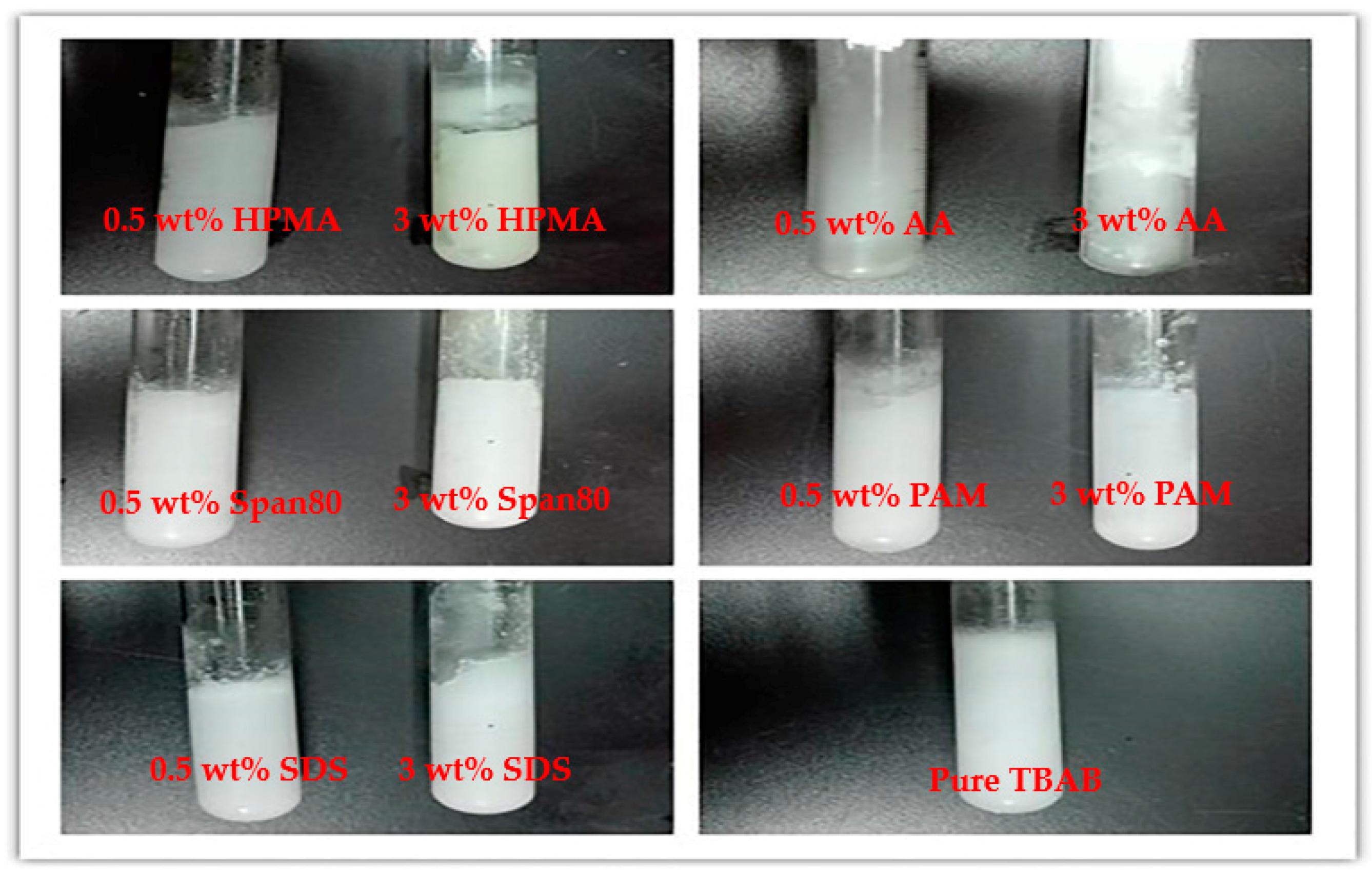
2.1. Anti-Agglomerant Screening

The results of eleven hydrate anti-agglomeration experiments are listed in Table 1, and the photographs of TBAB hydrate with different anti-agglomerants are shown in Figure 1. After the inert gas bubbling, the TBAB hydrate generated rapidly in one minute, and the hydrates exhibited a state of slurry. After half an hour, only the hydrates in the tubes with Span80 and cocamidopropyl dimethylamine and 10% glycerol (AA) addition still exhibited slurry state, and another an hour later, only the hydrate in the tube with AA addition kept the state of slurry. The hydrates with the other anti-agglomerants addition agglomerated into block solid in 1.5 h. Thus, AA is determined to be the most effective anti-agglomerant.

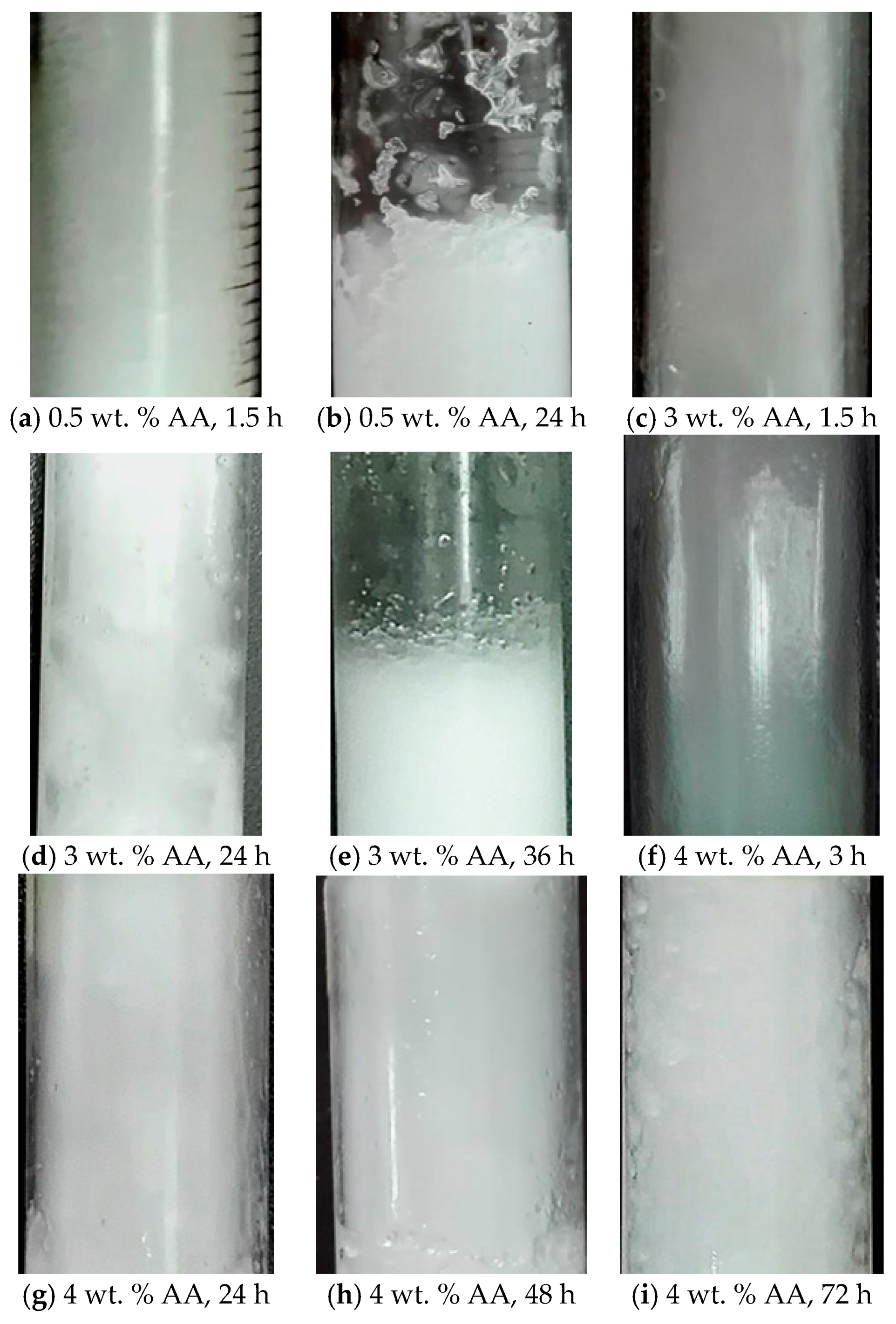
2.2. Effect of Anti-Agglomerant Dosage on Its Anti-Agglomeration Duration

The stable time of hydrate slurry is an important parameter for assessing the performance of anti-agglomerant. The photographs of TBAB hydrate with different amounts of AA addition are displayed in Figure 2. The TBAB concentration is 16.2 wt. %. The optimal anti-agglomerant concentration was determined by measuring the stable time of the hydrate slurry. As shown in Figure 2, after 24 h, the hydrate with 0.5 wt. % AA agglomerated, while the hydrates with 3.0 wt. % AA still maintained the state of slurry. However, another 12 h later, the hydrate slurry with 3.0 wt. % AA addition also exhibited agglomeration. As the AA dosage increased to 4 wt. %, the TBAB hydrate slurry remained anti-agglomeration up to 72 h. This indicates that the anti-agglomeration duration of AA is positively correlated with its concentration used. The minimum AA dosage required for 16.2 wt. % TBAB solution to maintain slurry state in 72 h is about 4 wt. %.

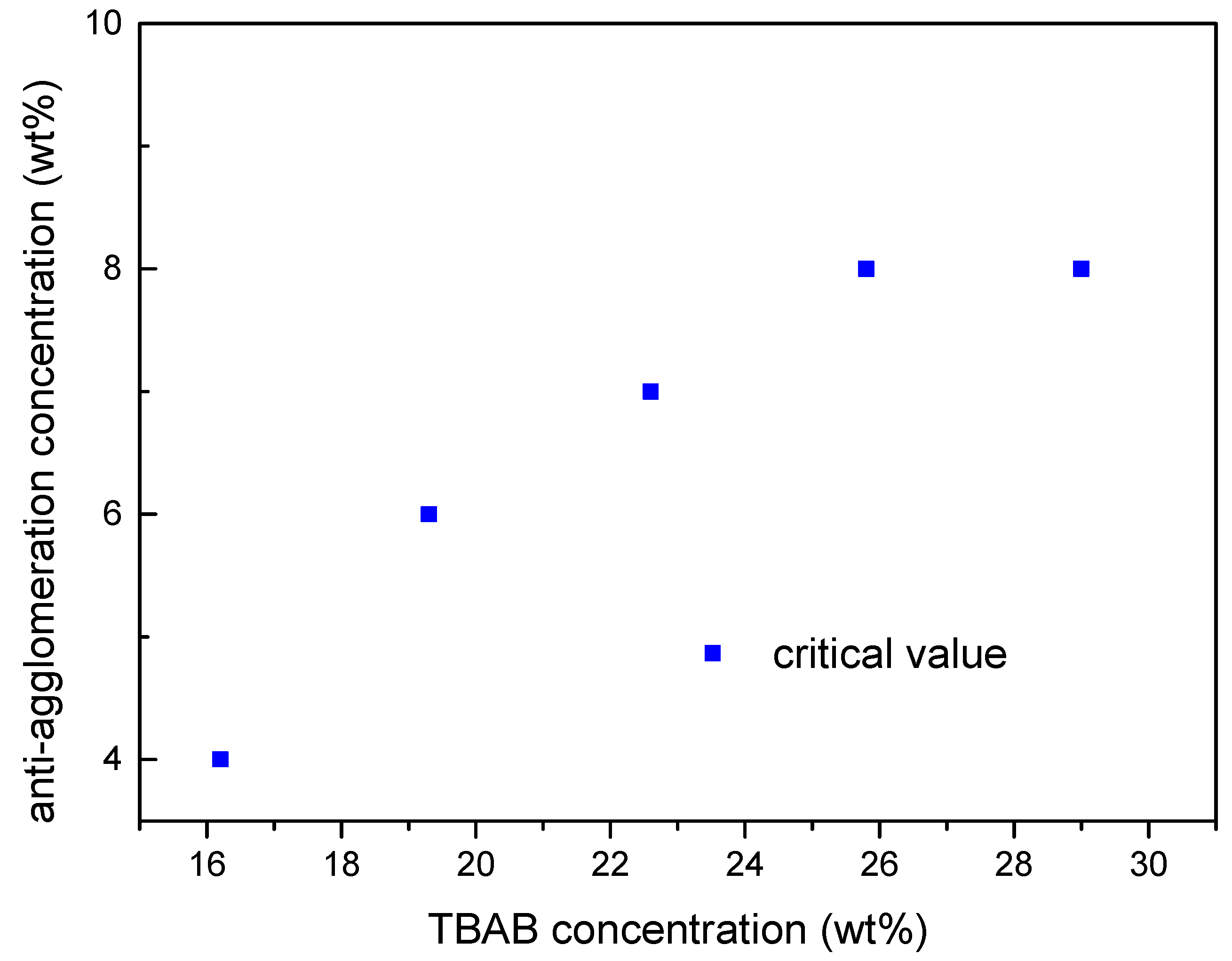
2.3. Effect of TBAB Concentration on AA′s Critical Concentration Needed

In this work, the minimum AA concentration needed to prevent TBAB hydrate from agglomerating within 72 h is defined as AA′s critical concentration. The stepwise method to increase AA concentration was used to determine the anti-agglomerant critical concentration in our experiments. Figure 3 shows the AA′s critical concentration for TBAB aqueous solutions with different concentrations. The AA′s critical concentration increases with TBAB concentration when TBAB concentration is lower than 26.0 wt. %, and then levels off when TBAB concentration increases further.

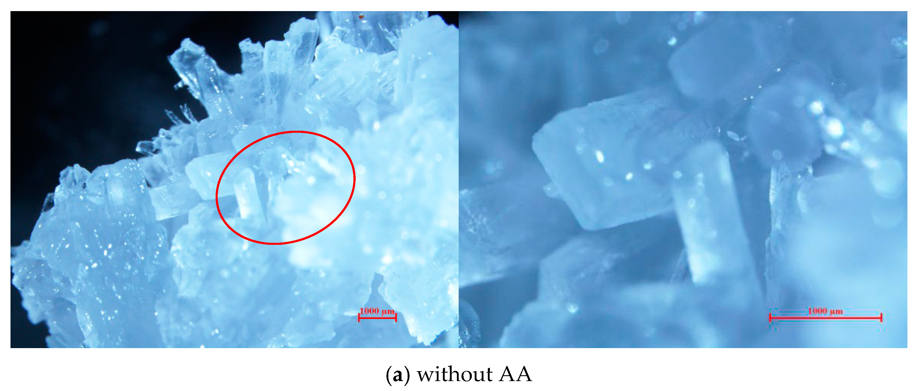
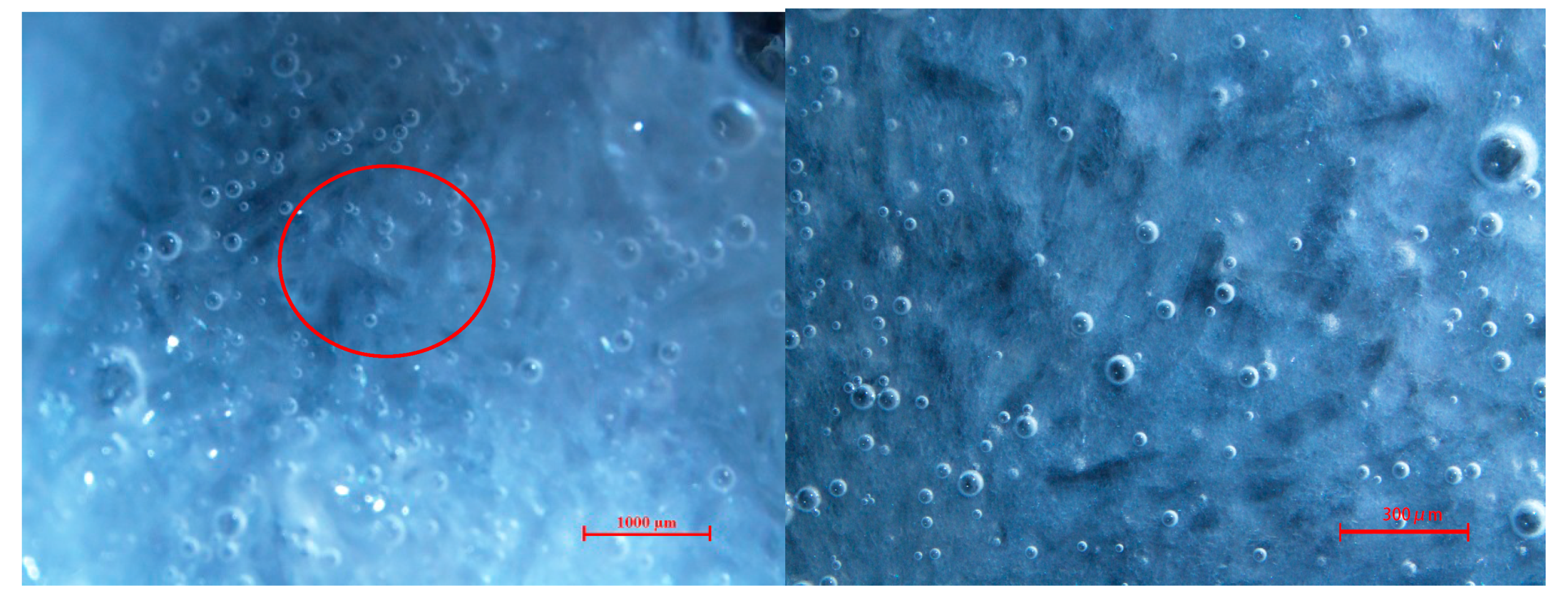
2.4. Micromorphology of TBAB Hydrate Slurry

The micrographs of TBAB hydrate with and without AA addition are shown in Figure 4. The photos on the right-hand side are the enlarged view of the red circle in the photos of the left side. Figure 4a shows the micromorphology of hydrate crystals generated in the TBAB system. It could be found that the pure TBAB hydrate particles are rod-like crystal of relatively large size that stick together and grows in clusters. Figure 4b shows the morphology of hydrate formation in the TBAB/AA system; it can be seen that the TBAB hydrate particles with small size are dispersed in the solution. This indicates that the anti-agglomerant played an important role in preventing TBAB hydrate particles from aggregation. However, the anti-agglomeration mechanism of AA still needs further study.

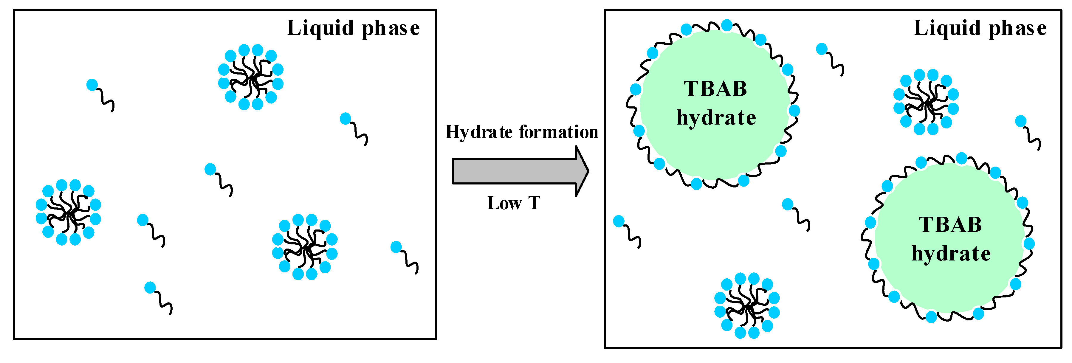
2.5. Analysis of the AA’s Anti-Agglomeration Mechanisms

In the past, the formation of water-in-oil emulsions has been proposed as a requirement for hydrate anti-agglomeration [11,16,18,19,20]. However, the AA proposed in this work is effective in an oil-free system. The anti-agglomeration mechanisms of AA are schematically shown in Figure 5 [21]. The nonionic surfactant cocamidopropyl dimethylamine forms micelles in the aqueous solution before hydrate generation. Because the hydrogen bonds between amino groups and water molecules is stronger than hydrogen bonds between water molecules, the cocamidopropyl dimethylamine can form hydrogen bonds with the water molecules on the surface of the hydrates. Once hydrates form in the solution, some of the micelles dissociate and the cocamidopropyl dimethylamine molecules adsorb on the surface of hydrate crystal nucleus. Meanwhile, the hydrophobic tail of the surfactant will cover the surface of the hydrate particles because the dielectric constant of TBAB hydrates is less than that of water [21], thus preventing the hydrates from growth and further agglomeration.

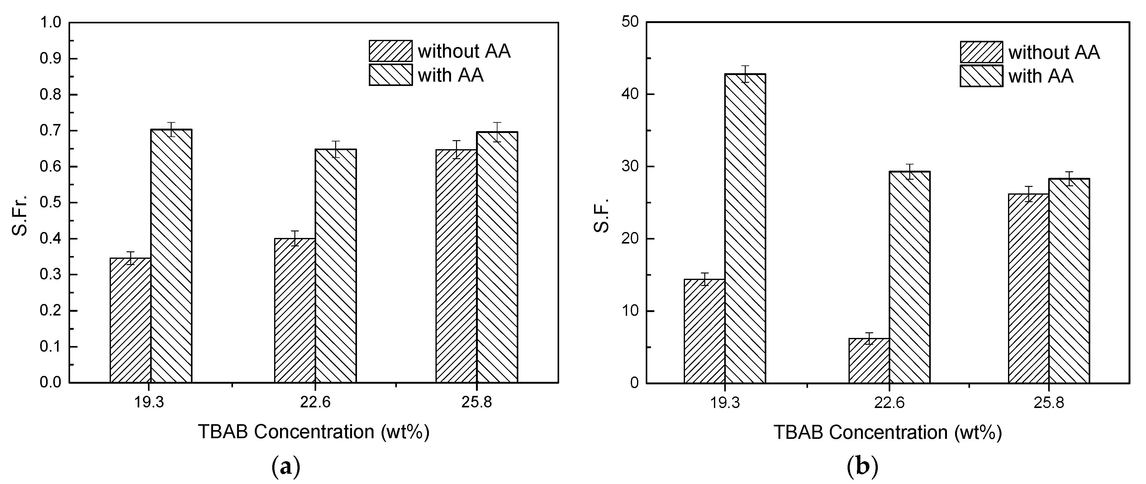
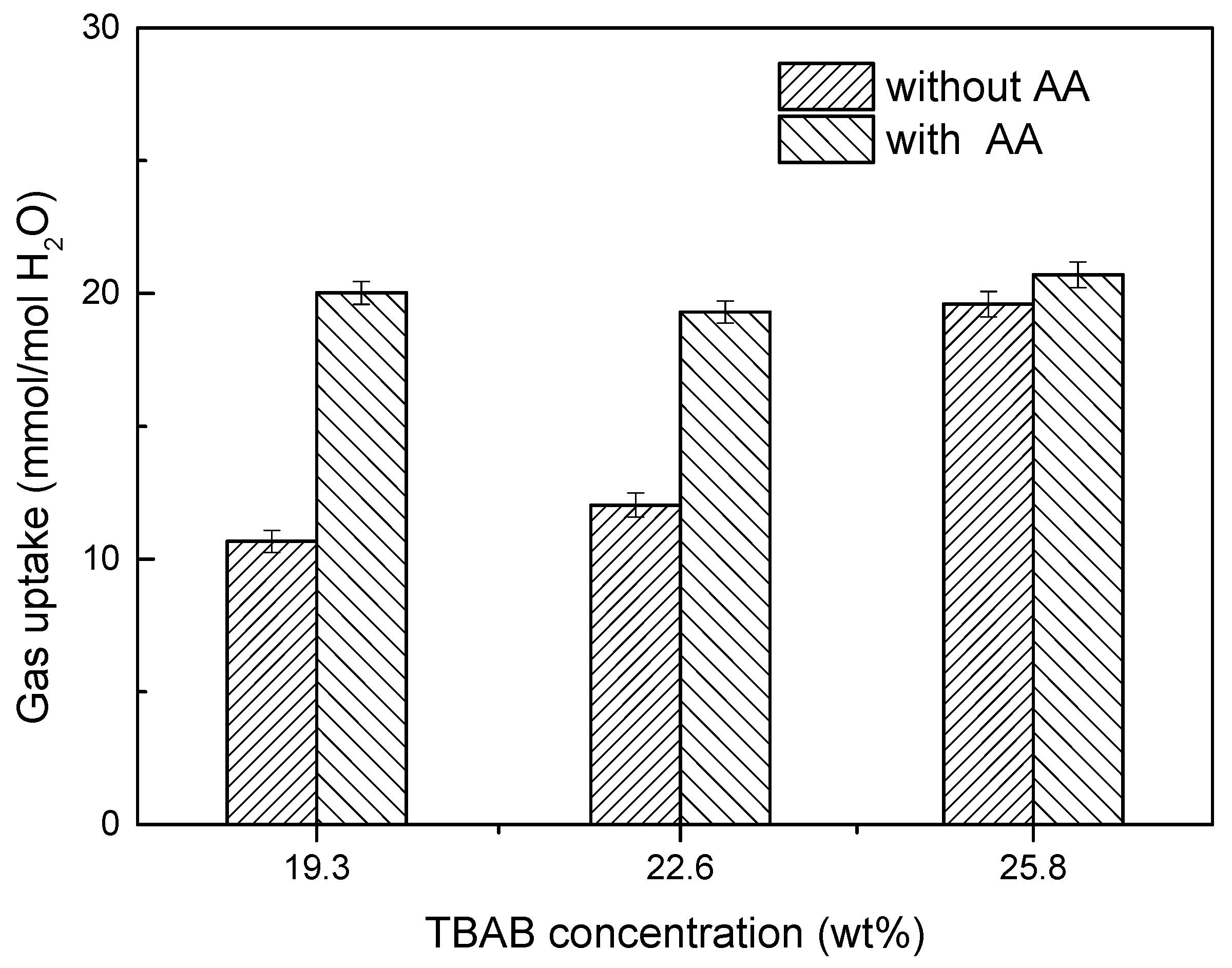
2.6. Effect of AA’s Anti-Agglomeration on CO2 Separation

In order to study the effect of AA addition on CO2 separation efficiency, six groups of comparative experiments were conducted at the initial conditions of 277.15 K and 4.000 MPa. The gas-liquid ratio was 210 vol %/125 vol %. The experiment conditions and results are listed in Table 2. As can be seen from Table 2, the CO2 concentration in residual gas decreased from 30.62% (in TBAB system) to 17.33% (in TBAB/AA binary system) with AA addition.
Figure 6 and Figure 7 display the gas storage capacity, CO2 split fraction and CO2 separation factor under different separating conditions, respectively.
As can be seen from Figure 6, for the same TBAB concentration, the gas storage capacity of hydrate formation in the presence of AA was much higher than that without AA. Taking 19.3 wt. % TBAB as an example, relative to pure a TBAB system, the gas storage capacity of hydrate formation in the TBAB/AA binary system increased by 87.8% (from 10.66 mmol/mol H2O to 20.02 mmol/mol H2O). This is because TBAB hydrate particles would agglomerate and adhere together in the process of hydrate formation without AA addition, thus preventing the CO2 from getting into the TBAB hydrate cage. As for TBAB/AA binary system with the same TBAB concentration, the presence of AA can prevent TBAB hydrate aggregation, thus can increase the contact area between CO2 and TBAB hydrate particles, so that more CO2 gas can get into TBAB cages. For a pure TBAB system, the gas storage capacity increased with TBAB concentration. However, for the TBAB/AA binary system, the gas storage capacity was approximately equal in three different TBAB/AA binary systems, which means the synergistic effect of AA and TBAB on hydrate-based CO2 separation was weakened with the increase in TBAB concentration. This is because the amount of TBAB hydrate cages generated in the solution increased with TBAB concentration in the pure TBAB system, so that more CO2 gas can get into the cages even if hydrate particles adhere to each other. TBAB hydrate particles would disperse in the solution with AA addition, thus increases the contact area between gas phase and hydrate particles, which will lead to an increase of gas transfer. Actually, because only 512 cavity of TBAB hydrate can accommodate gas molecules, and each TBAB hydrate has three 512 cavity, 1 mole TBAB hydrate can capture 3 mol CO2. The amount of CO2 in the feed gas was about 1.55 mol, thus the amount of CO2 relative to the amount of TBAB cages was insufficient in the three concentrations (as shown in Table 3). Therefore, after achieving phase equilibrium, the gas storage capacity was approximately equal in three different TBAB/AA binary systems even if the TBAB hydrate particles dispersed in the solution.
As can be seen from Figure 7, the CO2 split fractions of hydrate formation in TBAB/AA binary system are higher than that in TBAB system without AA. The CO2 separation factor of hydrate-based CO2 separation increased significantly in the TBAB solution containing AA. On the basis of these, it could be concluded that the addition of AA has positive effect on hydrate-based CO2 separation in TBAB solution.
The comparison of CO2 separation results using TBAB as the promoter is shown in Table 4. The CO2 spilt fraction of TBAB/AA system obtained in this work increased by 49.6% compared to the highest value reported in the literature [22]. This is mainly because the concentration of TBAB used in this work was much higher than that in Gholinezhad et al. [22], and the addition of AA can effectively disperse TBAB hydrate particles, so more CO2 can get into TBAB cages.

3. Materials and Methods
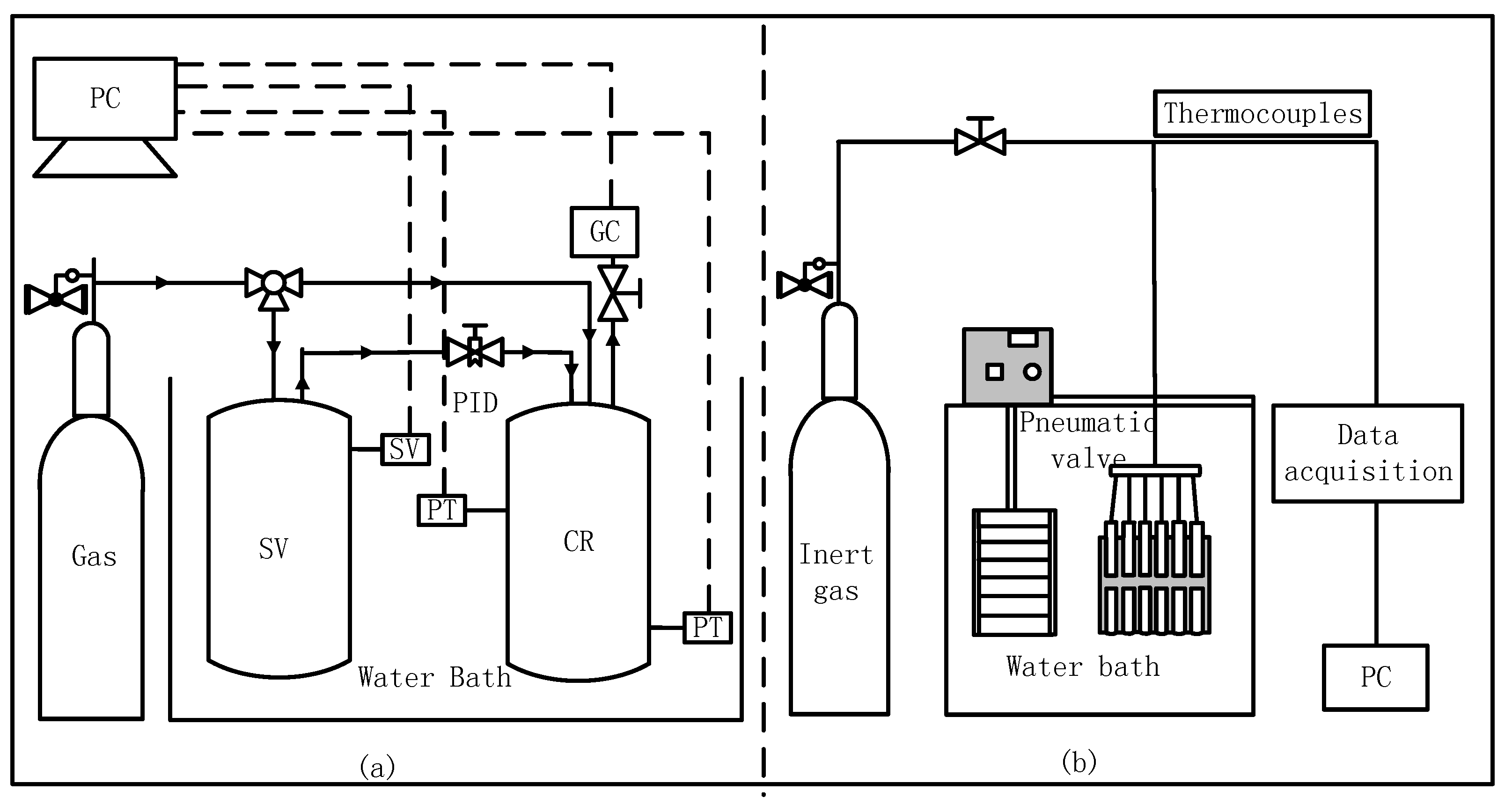
3.1. Apparatus

Figure 8a shows a schematic diagram of CO2 separation apparatus used for hydrate kinetic study. The experimental equipment mainly consists of a cylindrical crystallizer (CR) and a balance tank (SV), which are immersed in a water bath for temperature control. CR and SV are made of high-pressure stainless steel, so as to withstand pressure up to 25 MPa, and the inner volume is 336 mL and 1350 mL, respectively. The temperature and pressure of CR and SV are measured by a Pt100 temperature sensor (JM6081, Hefei Heavy Tripod Machinery and Electrical Equipment Co., Ltd., Hefei, China.) with an accuracy of ±0.1 K and a pressure sensor (Model 552, Boxborough, MA, USA) with an accuracy of ±0.02 MPa, respectively. All the temperature and pressure data are collected and stored in a computer (PC). There are two visualization windows on the front and back of the CR to observe the process of hydrate formation. The CR is equipped with an electromagnetic stirrer (400 r/min, Chengbang Science and Technology Co., Ltd., Sichuan, China) for accelerating the gas and liquid mixing. The pressure of CR can be maintained at a stable value through the PID control valve (E-ATR-7/250/I, Atos Co., Ltd., Sesto Calende, Italy) between CR and SV. The composition of residual gas in the CR after the hydrate formation and dissociation were analyzed by gas chromatography (GC522, Shanghai Wufeng Scientific Instrument Co., Ltd., Shanghai, China).
The anti-agglomerant screening device diagram is shown in Figure 8b. A series of tubular reactors are placed in a low-temperature water bath (Model XT5218-B12, Xutemp Temptech Co., Ltd., Hangzhou, China) for temperature control, with an accuracy of ±0.1 K and range from −25 to 90 °C. The inert gas was introduced to the bottom of the tubular reactor through the pressure-reducing valve (115H-200, Gentec (Shanghai) Corporation, Shanghai, China) and pneumatic valve (PK4, Changzhou Chvird Automation Equipment Co., Ltd., Changzhou, China) to agitate the solution by bubbling. The temperatures of the aqueous solution in the tubular reactors were measured by temperature sensors, and collected by the Agilent Data Acquirement System (34970A, Agilent technologies Co., Ltd., China).

3.2. Materials

All aqueous solutions were prepared by the deionized water (with 18.25 MΩ/cm resistivity) produced by an ultra-pure water system (GREEN-10T, Nanjing EPED Science and Technology Development Co., Ltd., Nanjing, China.). All chemical reagents used in this work are analytically pure, and are listed in Table 5.
Five kinds of polymerization inhibitors used in this work are polymaleic acid (HPMA), AA (90% cocamidopropyl dimethylamine + 10% glycerol), Span80, polyacrylamide (PAM) and sodium dodecyl sulfate (SDS). Polymaleic acid has good scale inhibition performance and can also be used to improve the dispersion of particles. The anti-agglomerant named AA in this work consisted of 90% cocamidopropyl dimethylamine and 10% glycerol. Cocamidopropyl dimethylamine is a kind of nonionic surfactant, and Sun et al. [21] found the surfactant can effectively prevent methane hydrate agglomeration in oil-free systems. Glycerol is a kind of hydrophilic substance, thus can play the role of co-solvent and increase the solubility of cocamidopropyl dimethylamine in water. Span 80 is a kind of lipophilic nonionic surfactant with an HLB of 4.3 and can prevent the agglomeration of tetrahydrofuran hydrate [25]. Polyacrylamide is a kind of water-soluble polymer compound, which can effectively reduce the frictional resistance of the fluid. Sodium dodecyl sulfate is highly hydrophilic and can effectively reduce the surface tension of the solution.

3.3. Methods

3.3.1. Anti-Agglomerant Screening Experiments

Eleven tubular reactors were used for anti-agglomerant screening. Each reactor contained 30 mL 0.5 mol/L TBAB aqueous solution and different concentration of anti-agglomerant. The temperature of the water bath was set as 275.15 K. Once the solution temperatures in these reactors reached a steady state, the inert gas bubbling started to agitate the solutions. After the hydrate formation, the photograph of hydrate slurry was taken to evaluate the anti-agglomeration performance of the anti-agglomerant.

3.3.2. Observation of Micromorphology of TBAB Hydrate

The hydrate samples generated from pure TBAB solution and TBAB/AA binary system were placed under the electron microscopy (Nikon SMZ1500, Nikon Corporation, Tokyo, Japan), and adjusted to the appropriate focal length and magnification, then pictures for recording were taken.

3.3.3. CO2 Hydrate Separation Experiments

For every experimental run, a cylindrical crystallizer (CR) was first filled with 125 mL aqueous solution with additive and pressurized with the simulated syngas to 4.000 MPa. Once CR was stabilized at 277.15 K, the agitator was turned on and the hydrate formation was awaited, and all the experimental data began to be recorded with time. After the hydrate formation finished, the residual gas phase in CR was sampled and analyzed by GC. Subsequently, the residual gas was quickly drained out of CR. After that, the temperature in CR was elevated to 293.15 K to make the hydrate dissociate completely. Finally, the composition of the gas phase from hydrate decomposition was analyzed by GC, each gas phase sample was measured three times and the test results averaged.
According to the mass conservation law, the total amount of gas is composed of the gas dissolved in the water, the gas encaged in the hydrate and the gas remaining in the residual gas phase. The amount of gas consumed during the hydrate formation (∆nH) includes the gas dissolved in the water and the gas encaged in the hydrate, which can be calculated as follows [5]:
n G , 0 = Δ n H + n G , t
Δ n H = ( P V z R T ) G , 0 ( P V z R T ) G , t
where z is the compressibility factor calculated by Pitzer’s correlation [26], subscript t refers to time, subscript 0 refers to the initial time, subscript G refers to the gas phase in the CR.
The split fraction and separation factor can be evaluated according to the following equations [27]:
S . F r . = n C O 2 H n C O 2 F e e d
S . F . = n C O 2 H × n H 2 G n C O 2 G × n H 2 H
where S.Fr. and S.F. refer to separation fraction and separation factor, respectively. n C O 2 F e e d , n C O 2 H and n C O 2 G defined as the mole number of CO2 in feed gas, in hydrate phase and in residual gas, respectively. n H 2 G and n H 2 H is the mole number of H2 in residual gas and in hydrate phase, respectively.

4. Conclusions

In this work, we screened out a kind of anti-agglomerant AA (90% cocamidopropyl dimethylamine +10% glycerol) that can prevent TBAB hydrate from agglomerating effectively. The anti-agglomerating performance and mechanisms of AA were studied by TBAB hydrate formation experiment and microscopic observation by electron microscope. The effect of AA anti-agglomerant addition on CO2 hydrate separation was studied by IGCC syngas separating experiments using TBAB as the hydrate formation promoter. The conclusions obtained are as follows:
  • The minimum AA dosage required increases with TBAB concentration in solution. A 6–8 wt. % AA addition can effectively prevent hydrate particles agglomeration in 19.3–29 wt. % TBAB aqueous solution. The TBAB hydrates slurry maintains stable over 72 h.
  • The micromorphology of hydrate particles shows that the addition of AA reduces the particle size of TBAB hydrate markedly because the cocamidopropyl dimethylamine molecules absorbs on the surface of TBAB hydrate crystal nucleus and forms a steric hindrance in the process of hydrate particle growth and agglomeration.
  • The IGCC syngas hydrate separating results indicate that AA addition can not only effectively prevent TBAB-CO2 hydrate agglomeration and the blockage of the separating equipment, but also improve the gas transfer in the phase of the hydrate slurry, thus increase the hydrate separation efficiency drastically.
  • Compared to the separating results without AA addition, the CO2 concentration in residual gas decreased from 30.62% to 17.33% with AA addition. Gas storage capacity, CO2 split fraction and separation factor increased significantly, and CO2 split fraction and separation factor reached 70.3% and 42.8%, respectively.

Acknowledgments

This work was supported by the grants from the National Natural Science Foundation of China (51576202, 51476174, 51736009), International S&T Cooperation Program of China (No.2015DFA61790) and National Key Research and Development Plan of China (No.2016YFC0304002), which are gratefully acknowledged.

Author Contributions

All the authors contributed to publish this paper. Rong Li, Xiao-Sen Li and Zhao-Yang Chen conceived and designed the experiments; Rong Li, Zhao-Yang Chen and Chun-Gang Xu performed the experiments and wrote the paper; Yu Zhang and Zhi-Ming Xia prepared for the experiments and analyzed the data.

Conflicts of Interest

The authors declare no conflict of interest.

References and Notes

  1. Wigley, T.M.L.; Jain, A.K.; Joos, F.; Nyenzi, B.S.; Shukla, P.R. Implications of Proposed CO2 Emissions Limitations; IPCC Technical Paper 4; Intergovernmental Panel on Climate Change: Geneva, Switzerland, 1997. [Google Scholar]
  2. Freund, P.; Ormerod, W.G. Progress toward storage of carbon dioxide. Energy Convers. Manag. 1997, 38, S199–S204. [Google Scholar] [CrossRef]
  3. Hendricks, C.A.; Blok, K.; Turkenburg, W.C. Technology and cost of recovering and storing carbon-dioxide from an integratedgasifier, combined-cycle plant. Energy 1991, 16, 1277–1293. [Google Scholar] [CrossRef]
  4. Duc, N.H.; Chauvy, F.; Herri, J.M. CO2 capture by hydrate crystallization—A potential solution for gas emission of steelmaking industry. Energy Convers. Manag. 2007, 48, 1313. [Google Scholar] [CrossRef]
  5. Linga, P.; Kumar, R.N.; Englezos, P. Gas hydrate formation from hydrogen/carbon dioxide and nitrogen/carbon dioxide gas mixtures. Chem. Eng. Sci. 2007, 62, 4268–4276. [Google Scholar] [CrossRef]
  6. Lee, H.J.; Lee, J.D.; Linga, P.; Englezos, P.; Kim, Y.S.; Lee, M.S.; Kim, Y.D. Gas hydrate formation process for pre-combustion capture of carbon dioxide. Energy 2009, 35, 2729–2733. [Google Scholar] [CrossRef]
  7. Kumar, R.; Linga, P.; Ripmeester, J.A.; Englezos, P. Two-stage clathrate hydrate/membrane process for precombustion capture of carbon dioxide and hydrogen. J. Environ. Eng. ASCE 2009, 135, 411–417. [Google Scholar] [CrossRef]
  8. Zhang, J.S.; Yedlapalli, P.; Lee, J.W. Thermodynamic analysis of hydrate-based pre-combustion capture of CO2. Chem. Eng. Sci. 2009, 64, 4732–4736. [Google Scholar] [CrossRef]
  9. Kang, S.P.; Lee, H. Recovery of CO2 from flue gas using gas hydrate: Thermodynamic verification through phase equilibrium measurements. Environ. Sci. Technol. 2000, 34, 4397–4400. [Google Scholar] [CrossRef]
  10. Mokhatab, S.; Wilkens, R.J.; Leontaritis, K.J. A review of strategies for solving gas-hydrate problems in subsea pipelines. Energy Source Part A 2007, 29, 39–45. [Google Scholar] [CrossRef]
  11. Huo, Z.; Freer, E.; Lamar, M.; Sannigrahi, B.; Knauss, D.M.; Sloan, E.D. Hydrate plug prevention by anti-agglomeration. Chem. Eng. Sci. 2001, 56, 4979–4991. [Google Scholar] [CrossRef]
  12. Huangjing, Z.; Minwei, S.; Abbas, F. Anti-agglomeration of natural gas hydrates in liquid condensate and crude oil at constant pressure conditions. Fuel 2016, 180, 187–193. [Google Scholar]
  13. Sugier, A.; Bourgmayer, P.; Behar, E.; Freund, E. EP 323307, 5 July 1989.
  14. Sugier, A.; Bourgmayer, P.; Behar, E.; Freund, E. EP 323774, 12 July 1989.
  15. Sugier, A.; Bourgmayer, P.; Stern, R. EP 323775, 12 July 1989.
  16. Zanota, M.L.; Dicharry, C.; Graciaa, A. Hydrate plug prevention by quaternary ammonium salts. Energy Fuels 2005, 19, 584–590. [Google Scholar] [CrossRef]
  17. Kelland, M.A.; Svartaas, T.M.; Ovsthus, J.; Tomita, T.; Chosa, J. Studies on some zwit-terionic surfactant gas hydrate anti-agglomerants. Chem. Eng. Sci. 2006, 61, 4048–4059. [Google Scholar] [CrossRef]
  18. Sloan, E.D. A changing hydrate paradigm—From apprehension to avoidance to risk management. Fluid Phase Equilib. 2005, 228, 67–74. [Google Scholar] [CrossRef]
  19. Mehta, A.P.; Hebert, P.B.; Cadena, E.R.; Weatherman, J.P. Fulfilling the promise of low-dosage hydrate inhibitors: Journey from academic curiosity to successful field implementation. SPE Prod. Facil. 2003, 18, 73–79. [Google Scholar] [CrossRef]
  20. Sloan, E.D.; Koh, C.A. Clathrate Hydrates of Natural Gases; CRC: Boca Raton, FL, USA, 2008. [Google Scholar]
  21. Sun, M.; Firoozabadi, A. New surfactant for hydrate anti-agglomeration in hydrocarbon flowlines and seabed oil capture. J. Colloid. Interface Sci. 2013, 402, 312–319. [Google Scholar] [CrossRef] [PubMed]
  22. Jebraeel, G.; Antonin, C.; Bahman, T. Separation and capture of carbon dioxide from CO2/H2 syngas mixture using semi-clathrate hydrates. Chem. Eng. Res. Des. 2011, 89, 1747–1751. [Google Scholar]
  23. Xu, C.; Zhang, S.; Cai, J.; Chen, Z.; Li, X. CO2 (carbon dioxide) separation from CO2-H2 (hydrogen) gas mixtures by gas hydrates in TBAB (tetra-n-butyl ammonium bromide) solution and Raman spectroscopic analysis. Energy 2013, 59, 719–725. [Google Scholar] [CrossRef]
  24. Soo, M.K.; Ju, D.L.; Hyun, J.L.; Eun, K.L.; Yangdo, K. Gas hydrate formation method to capture the carbon dioxide for pre-combustion process in IGCC plant. Int. J. Hydrogen Energy 2011, 36, 1115–1121. [Google Scholar]
  25. Taylor, C.J.; Dieker, L.E.; Miller, K.T.; Koh, C.A.; Sloan, E.D., Jr. Micromechanical adhesion force measurements between tetrahyfrofuran hydrate particles. J. Colloid Interface Sci. 2007, 306, 255–261. [Google Scholar] [CrossRef] [PubMed]
  26. Smith, J.M.; Van Ness, H.C.; Abbott, M.M. Introduction to Chemical Engineering Thermodynamics; McGraw-Hill: New York, NY, USA, 2001. [Google Scholar]
  27. Praveen, L.; Rajnish, K.; Peter, E. The clathrate hydrate process for post and pre-combustion capture of carbon dioxide. J. Hazard. Mater. 2007, 149, 625–629. [Google Scholar]
Figure 1. Photograph of Tetrabutylammonium bromide (TBAB) hydrate with different anti-agglomerants after 1.5 h.
Energies 11 00399 g001
Figure 2. The photographs of TBAB hydrate with different amount of 90% cocamidopropyl dimethylamine +10% glycerol (AA) addition.
Energies 11 00399 g002
Figure 3. AA′s critical minimum concentration for different TBAB solutions.
Energies 11 00399 g003
Figure 4. Micrographs of TBAB hydrate.
Energies 11 00399 g004aEnergies 11 00399 g004b
Figure 5. Anti-agglomeration mechanisms of AA.
Energies 11 00399 g005
Figure 6. Gas storage capacity in different conditions.
Energies 11 00399 g006
Figure 7. CO2 split fraction (a) and separation factor (b) in different conditions.
Energies 11 00399 g007
Figure 8. Schematic diagram of experimental equipment. (a) CO2 separation apparatus; (b) Anti-agglomerant screening device.
Energies 11 00399 g008
Table 1. Results of anti-agglomerant screening.
No.Anti-Agglomerant T B A B a w t . % A A b w t . % V c m L T d K t e h Result f
1HPMA g0.516.230275.151.5No
2HPMA3.016.230275.151.5No
3AA h0.516.230275.151.5Yes
4AA3.016.230275.151.5Yes
5Span800.516.230275.151.5No
6Span803.016.230275.151.5No
7PAM i0.516.230275.151.5No
8PAM3.016.230275.151.5No
9SDS j0.516.230275.151.5No
10SDS3.016.230275.151.5No
11-016.230275.151.5No
a Mass concentration of anti-agglomerant, with accuracy of ±0.01 g. b Mass concentration of tetra-n-butyl ammonium bromide, with accuracy of ±0.01 g. c Volume of tetra-n-butyl ammonium bromide aqueous solution, with accuracy of ±0.1 mL. d Experimental temperature, with accuracy of ±0.1 K. e Duration of experiment. f Yes refers to anti-agglomeration, no refers to aggregation. g Polymaleic acid. h 90% cocamidopropyl dimethylamine +10% glycerol. i Polyacrylamide. j Sodium dodecyl sulfate.
Table 2. Experimental conditions and results for simulated syngas hydrate separation with different additives.
Experiment No. T B A B a w t . % A A b w t . % T c K P d M P a L / G V O L % / V O L % X G e % S.Fr.fS.F.g
119.30277.154.000125/21030.620.34614.4
219.36277.154.000125/21017.330.70342.8
322.60277.154.000125/21029.810.4016.2
422.67277.154.000125/21019.970.64829.3
525.80277.154.000125/21020.250.64726.2
625.88277.154.000125/21017.960.69628.3
a Mass concentration of tetra-n-butyl ammonium bromide, with accuracy of ±0.01 g. b Mass concentration of anti-agglomerant, with accuracy of ±0.01 g. c Experimental temperature, with accuracy of ±0.1 K. d Experimental initial pressure, with accuracy of ±0.02 MPa. e Concentration of CO2 in the residual gas phase, with accuracy of ±0.1%. f Split fraction of CO2. g Separation factor.
Table 3. Theoretical value of CO2 storage in different conditions.
CTBAB/wt. %VTBAB/mLnTBAB/moln1CO2 a/moln2CO2 b/mol
19.31250.0750.2250.155
22.61250.0880.2640.155
25.81250.1000.3000.155
a Theoretical value of CO2 storage. b Mole number of CO2 in feed gas.
Table 4. Comparison of CO2 separation results using TBAB as the promoter.
ReferencesTBAB a T b K P c M P a L / G V O L % / V O L % S.Fr.S.F.
Gholinezhad et al. [22]5 and 10 wt. %273.5–273.93.8–3.9 50/5041–47%15.7–28.0
XU et al. [23]0.29 mol %274.153.0 180/12014.5%-
Kim et al. [24]0.5, 1.0 and 3.0 mol %284.15–287.153.0-10.1–24.1%16.1–26.0
This work19.3, 22.6 and 25.8 wt. %277.154.0125/21034.6–64.7%6.2–26.2
This work19.3, 22.6 and 25.8 wt. % with AA277.154.0125/21064.8–70.3%28.3–42.8
a Tetra-n-butyl ammonium bromide. b Experimental temperature, with accuracy of ±0.1 K. c Experimental initial pressure, with accuracy of ±0.02 MPa.
Table 5. The chemical reagents used in this work.
No.NamePuritySupplier
1TBAB99.0%Aladdin Industrial Corporation (Shanghai agent, China)
2Sodium dodecyl sulfate (SDS)analytical pureTianjin Fuchen Chemical Reagent Factory
3Span8099.0%Tianjin Kermel Chemical Reagent Factory Co., Ltd.
4Polyacrylamide (PAM)MW. 5 millionShanghai Macklin Biochemicals Co., Ltd.
5Polymaleic acid50 vol %Shanghai Macklin Biochemicals Co., Ltd.
6Cocamidopropyl dimethylamine Shanghai Yincong New Material Technology Co., Ltd.
7Glycerin99.0%MYM Biological Technology Co., Ltd.
8Simulated syngas39.98 mol % CO2 + 60.02 mol % H2Huate Gas Co., Ltd., China.

